US3072930A - Spaced tube inflatable life raft - Google Patents
Spaced tube inflatable life raft Download PDFInfo
- Publication number
- US3072930A US3072930A US24592A US2459260A US3072930A US 3072930 A US3072930 A US 3072930A US 24592 A US24592 A US 24592A US 2459260 A US2459260 A US 2459260A US 3072930 A US3072930 A US 3072930A
- Authority
- US
- United States
- Prior art keywords
- elements
- raft
- inflatable
- bulkheads
- disposed
- Prior art date
- Legal status (The legal status is an assumption and is not a legal conclusion. Google has not performed a legal analysis and makes no representation as to the accuracy of the status listed.)
- Expired - Lifetime
Links
Images

Classifications
-
- B—PERFORMING OPERATIONS; TRANSPORTING
- B63—SHIPS OR OTHER WATERBORNE VESSELS; RELATED EQUIPMENT
- B63C—LAUNCHING, HAULING-OUT, OR DRY-DOCKING OF VESSELS; LIFE-SAVING IN WATER; EQUIPMENT FOR DWELLING OR WORKING UNDER WATER; MEANS FOR SALVAGING OR SEARCHING FOR UNDERWATER OBJECTS
- B63C9/00—Life-saving in water
- B63C9/02—Lifeboats, life-rafts or the like, specially adapted for life-saving
- B63C9/04—Life-rafts
- B63C2009/042—Life-rafts inflatable
-
- B—PERFORMING OPERATIONS; TRANSPORTING
- B63—SHIPS OR OTHER WATERBORNE VESSELS; RELATED EQUIPMENT
- B63C—LAUNCHING, HAULING-OUT, OR DRY-DOCKING OF VESSELS; LIFE-SAVING IN WATER; EQUIPMENT FOR DWELLING OR WORKING UNDER WATER; MEANS FOR SALVAGING OR SEARCHING FOR UNDERWATER OBJECTS
- B63C9/00—Life-saving in water
- B63C9/02—Lifeboats, life-rafts or the like, specially adapted for life-saving
- B63C9/04—Life-rafts
- B63C2009/044—Life-rafts covered
- B63C2009/046—Life-rafts covered reversible, i.e. deployable in upright or upside down positions
Definitions
- Aircraft having scheduled flights over large bodies of water carry life rafts which, when tossed from a plane, automatically inflate so that they may be boarded by survivors of abandoned aircraft and occupied pending ultimate rescue.
- the inflatable life rafts usually are constructed with two superimposed inflatable main buoyancy tubes disposed around their periphery and include a floor or deck secured between the tubes.
- a peripheral canopy and a roof are stored in the accessory kit ofthe raft and are erected manually after the raft is inflated. This type of protection often is very hard to erect because of high wind and waves.
- a life raft having an inflatable sheltering canopy disposed on an inflatable supporting framework has heretofore been proposed in the Bicknell et al. Patent No. 2,968,919.
- This raft provides adequate exposure protection, it is heavy7 bulky, and expensive to manufacture.
- the life raft shown in the Bicknell et al. patent is also single sided and, should the raft inflate while in the inverted position, it is necessary to right the raft before it can be boarded.
- lt is an object of the present invention to overcome the foregoing and other disadvantages of the prior art by providing a reversible life raft having exposure protection means ywhich are erected automatically during inflation of the raft.
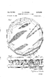
- PIG. l is a plan view of a life raft embodying the present invention.
- FlG. 2 is an elevational View of the life raft shown in FIG. 1;
- FIG. 3 is an enlarged vertical sectional view taken 0n line 3 3 of FG. 1;
- FIG. 4 is an enlarged verticalsectional View taken on line l4--4 of FIG. l;
- FiG. 5 is anenlarged perspective View of the ventilating and boarding openings with the flaps shown inthe open position.
- FIG. 6 is a schematic'perspective view of a-c'ompartmented arrangement of the inflatable ⁇ framework of the life raft.
- an inflatable life raft of the reversible type having a first flexible ⁇ panel 1f) consisting of water prooflfabric which is'secured and sealed along its outer periphery to a first peripherally disposed inllatable buoyant tube 11.
- a second flexible panel 112 consisting of water proof fabric which is secured and sealed along its outer periphery to a second peripherally disposed inflatable buoyancy tube 13.
- a plurality of peripherally spaced inflatable spacer tubes 15 are connected at one end to the first buoyancy tube 11 and at the other end to the second buoyancy tube 13.
- a flexible fabric spray shield or canopy composed of a plurality of segmental wall'panels 17 is secured to the peripheral tubes 11 and 13 and the supporting tubes 15.
- the spacer tubes 15 respectively communicate with the peripheral tubes 11 and 13 through orifices 19 and 2f).
- fluid will flow through the orifices 19 and 2@ and expand the tubes 15.
- the tubes 15 will maintain the peripheral tubes 11 and 13 in spaced relationship and either the panel 10 or the panel 12 will form the floor of the raft, the other panel automatically forming the roof.
- the panels 10 and 12 are respectively mounted on the outer tangency point of the tubes 11 and 13 to provide the maximum possible headroom inside the raft.
- the segmental Wall panels 17 of the spray shield are automatically drawn into a generally taut position as shown in FIG. 4 of the drawing.
- the spray shield is provided with diametrically opposed Ventilating and boarding openings 22 and'23.
- Each of the openings have a pair of flaps24 and 25 disposed to form a cover for the opening and adapted to be joined togetherby releasable means, such as slide fasteners 526.
- the flaps may be retained in the open position by--rncans kwellknown in the art, such as snap fasteners 27.
- the peripheral tube 13 is set back adjacent the opening 22 and the peripheral tube 11 is set back adjacent the opening 23 to facilitate boarding the raft from the airplane.
- a boarding stirrup 28 and boarding handles 29 are attached on the tube 11 adjacent the opening 22 to aid survivors to pull themselves onto the raft.
- a stirrup and boarding handles are provided on the diametrically opposite side of the raft on tube 13 adjacent the opening 23.
- Life lines 3f are looped around the outside and the inside (not shown) of the raft to serve as hand holds for survivors in the water and those inside the raft. Additional handles 31 may be placed on the panels 10 and 12 adjacent the openings 22 and 23.
- a pneumatic inflation assembly (not shown) of a type well known in the art may be provided for inflating the raft. Such an assembly is shown in the Bicknell et al. Patent No. 2,908,919.
- a compartmented type of inflatable supporting framework for the floor, roof and spray shield of the raft is shown schematically in FiG. 6 of the drawing.
- the top and bottom peripherially disposed inflatable buoyant tubes 11 and 13 are respectively shown divided into four compartments 32 and 34 by means of bulkheads 35 cemented or otherwise secured in place in the peripherally disposed tubes.
- Each bottom compartment 32 is connected through a vertical spacer tube 33 to a top compartment 34 that is 90 degrees out of phase with it to form individual framework members for supportingthe floor, roof and spray shield.
- the compartment 34 above it remains inflated to support the portion of the raft floor formerly supported by the punctured compartment 32.
- each of the individual fra'mework members may be separately inflated.
- two communicating tubes 36 are shown interconnecting adjacent framework members so that only a dual inflation system is required.
- the communicating tubes 36 are arranged to be closed immediately after the raft is boarded.
- the floor, roof and the spray shield or canopy may be made of double walled mattress type fabric instead of the single fabric sheet shown in the drawing.
- the floor, roof and spray shield may be connected to a different portion of the buoyant tubes from that shown in the drawing.
- An inflatable life raft comprising: spaced upper and lower superposed peripherally disposed inflatable buoyant elements; a plurality of inflatable spacer tubes extending between said elements; bulkheads in said elements dividing the elements into a plurality of compartments; each of said bulkheads being adjacent a spacer tube, the bulkheads of the upper element being disposed on the same side of the spacer tubes and the bulkheads of the lower element being disposed on the opposite side of the spacer tubes; a first flexible panel secured along its outer periphery to said plurality of compartments in said upper peripherally disposed element; a second flexible panel secured along its outer periphery to said plurality of compartments in said lower peripherally disposed element, said first and second flexible panels automatically forming spaced upper and lower surfaces when said buoyant elements are inflated; and -flexible wall means mounted on said buoyant elements and adapted to be erected automatically to form a peripheral spray shield when said buoyant elements are inflated.
- An inflatable life raft comprising: spaced upper and lower superposed peripherally disposed inflatable buoyant elements; a plurality of inflatable spacer tubes extending between said elements; bulkheads in said elements dividing the elements into a plurality of compartments; each of said bulkheads being adjacent a spacer tube, the bulkheads of the upper element being disposed on the same side of the spacer tubes ⁇ and the bulkheads of the lower element being disposed on the opposite side of the spacer tubes; a first flexible panel secured along its outer periphery to said plurality of compartments in said upper peripherally disposed element; a second flexible panel secured along its outer periphery to said plurality of compartments in said lower peripherally disposed element, said first and second flexible panels automatically forming spaced upper and lower surfaces when said buoyant elements are inflated; flexible wall means mounted on said buoyant elements and adapted to be -erected automatically to form a peripheral spray shield when said buoyant elements are inflated; said wall means having an opening forming an entryway; and means associated with said wall means for closing
- An inflatable life raft comprising: spaced upper and lower superposed peripherally disposed inflatable buoyant elements; a plurality of inflatable spacer tubes extending between said elements; bulkheads in said elements dividing the elements into a plurality of compartments; each of said bulkheads being adjacent a spacer tubethe bulkheads of the upper element being disposed on the same side'of the spacer tubes and the bulkheads of the lower element being disposed on the opposite side of the spacer tubes; a rst flexible panel secured along its outer periphery to said plurality of compartments in said upper peripherally disposed element; a second flexible panel secured along its outer periphery to said plurality of compartments in said lower peripherally dispos-ed element, said rst and second flexible panels automatically forming spaced upper and lower surfaces when said buoyant elements are inflated; flexible wall means mounted on said buoyant elements and adapted to be erected automatically to form a peripheral spray shield when said buoyant elements are inflated, said wall means having an opening forming an entryway; the buoyant element
Landscapes
- Engineering & Computer Science (AREA)
- Mechanical Engineering (AREA)
- Ocean & Marine Engineering (AREA)
- Tents Or Canopies (AREA)
Description
2 Sheets-Sheei'I 1 Filed April 25, 1960 ROBERT J. FRAEBEL,
Jan. 15, 1963 R. J. FRAEBEL sPAcED TUBE INFLATABLE LIFE RAFT 2 Sheets-Sheet 2 Filed April 25, 1960 INVENTORL ROBERT J. FRAEBEL,
Attorney.
www,"
United States Patent Office 3,072,930 Patented Jan.. :15, 1963 3,072,930 SPACE TUBE INFLATABLE LIFE RAFT Robert Si. Fraebel, Red Bank, NJ., assigner to The Garrett Corporation, Los Angeles, Calif., a corporation of California Filed ApnZS, 1960, Ser. No. 24,592 3 Claims. (Cl. 9-11) This invention relates to inflatable life rafts and particularly to life rafts provided with an sheltering roof and canopy.
Aircraft having scheduled flights over large bodies of water carry life rafts which, when tossed from a plane, automatically inflate so that they may be boarded by survivors of abandoned aircraft and occupied pending ultimate rescue. The inflatable life rafts usually are constructed with two superimposed inflatable main buoyancy tubes disposed around their periphery and include a floor or deck secured between the tubes. To provide shelter from the sun, rain or cold weather, a peripheral canopy and a roof are stored in the accessory kit ofthe raft and are erected manually after the raft is inflated. This type of protection often is very hard to erect because of high wind and waves.
In view of the above noted difficulty in erecting the canopy and roof, and because of the panic that may take place during ditching, it is desirable to have the canopy, roof and other exposure protection erected automatically when the raft is inflated. A life raft having an inflatable sheltering canopy disposed on an inflatable supporting framework has heretofore been proposed in the Bicknell et al. Patent No. 2,968,919. However, while this raft provides adequate exposure protection, it is heavy7 bulky, and expensive to manufacture. The life raft shown in the Bicknell et al. patent is also single sided and, should the raft inflate while in the inverted position, it is necessary to right the raft before it can be boarded.
lt is an object of the present invention to overcome the foregoing and other disadvantages of the prior art by providing a reversible life raft having exposure protection means ywhich are erected automatically during inflation of the raft.
it is another object of the invention to provide a reversible life raft having a floor, a roof, and a side wall canopy that are erected automatically when the life raft is inflated.
It is a further 'object of theinvention to provide a reversible lifel raft of the above described type constructed so as to have the same characteristics and to function in the same way with either side up.
It is a still further object of the invention to provide a life raft of the above described type that is light in weight, can be easily handled and is not expensive to manufacture.
It is still another object of the invention to provide a life raft of the above described type wherein the inflatable tubes forming the supporting framework for the floor, roof and canopy walls are divided into compartments, the compartments being arranged so that a puncture of the tube in one of the compartments will not seriously impair the rigidity of the raft.
Other and further objects of the present invention will become apparent from the disclosures in the following detailed specification, appended claims, and accompanying drawings, wherein:
PIG. l is a plan view of a life raft embodying the present invention;
FlG. 2 is an elevational View of the life raft shown in FIG. 1;
FIG. 3 is an enlarged vertical sectional view taken 0n line 3 3 of FG. 1;
FIG. 4 is an enlarged verticalsectional View taken on line l4--4 of FIG. l;
FiG. 5 is anenlarged perspective View of the ventilating and boarding openings with the flaps shown inthe open position; and
=FIG. 6 is a schematic'perspective view of a-c'ompartmented arrangement of the inflatable `framework of the life raft.
Referring to the drawings,fthere is shown an inflatable life raft of the reversible type having a first flexible `panel 1f) consisting of water prooflfabric which is'secured and sealed along its outer periphery to a first peripherally disposed inllatable buoyant tube 11.
Superposed in spaced relationship to the first panel 10 is a second flexible panel 112 consisting of water proof fabric which is secured and sealed along its outer periphery to a second peripherally disposed inflatable buoyancy tube 13.
As best seen in FlGS, 2 and 3, a plurality of peripherally spaced inflatable spacer tubes 15 are connected at one end to the first buoyancy tube 11 and at the other end to the second buoyancy tube 13. A flexible fabric spray shield or canopy composed of a plurality of segmental wall'panels 17 is secured to the peripheral tubes 11 and 13 and the supporting tubes 15.
The spacer tubes 15 respectively communicate with the peripheral tubes 11 and 13 through orifices 19 and 2f). Thus as the raft is inflated fluid will flow through the orifices 19 and 2@ and expand the tubes 15. When the raft is fully inflated, the tubes 15 will maintain the peripheral tubes 11 and 13 in spaced relationship and either the panel 10 or the panel 12 will form the floor of the raft, the other panel automatically forming the roof. As shown in FIGS. 3 and 4, the panels 10 and 12 are respectively mounted on the outer tangency point of the tubes 11 and 13 to provide the maximum possible headroom inside the raft. As the panels l1f) and112 assume the above described spaced position, the segmental Wall panels 17 of the spray shield are automatically drawn into a generally taut position as shown in FIG. 4 of the drawing.
The spray shield is provided with diametrically opposed Ventilating and boarding openings 22 and'23. Each of the openings have a pair of flaps24 and 25 disposed to form a cover for the opening and adapted to be joined togetherby releasable means, such as slide fasteners 526. The flaps may be retained in the open position by--rncans kwellknown in the art, such as snap fasteners 27.
As shown in FiG. l, the peripheral tube 13 is set back adjacent the opening 22 and the peripheral tube 11 is set back adjacent the opening 23 to facilitate boarding the raft from the airplane. A boarding stirrup 28 and boarding handles 29 are attached on the tube 11 adjacent the opening 22 to aid survivors to pull themselves onto the raft. Similarly, a stirrup and boarding handles are provided on the diametrically opposite side of the raft on tube 13 adjacent the opening 23.
Life lines 3f) are looped around the outside and the inside (not shown) of the raft to serve as hand holds for survivors in the water and those inside the raft. Additional handles 31 may be placed on the panels 10 and 12 adjacent the openings 22 and 23. A pneumatic inflation assembly (not shown) of a type well known in the art may be provided for inflating the raft. Such an assembly is shown in the Bicknell et al. Patent No. 2,908,919.
A compartmented type of inflatable supporting framework for the floor, roof and spray shield of the raft is shown schematically in FiG. 6 of the drawing. In this type of framework, the top and bottom peripherially disposed inflatable buoyant tubes 11 and 13 are respectively shown divided into four compartments 32 and 34 by means of bulkheads 35 cemented or otherwise secured in place in the peripherally disposed tubes. Each bottom compartment 32 is connected through a vertical spacer tube 33 to a top compartment 34 that is 90 degrees out of phase with it to form individual framework members for supportingthe floor, roof and spray shield. Thus if a bottom compartment 32 is punctured, the compartment 34 above it remains inflated to support the portion of the raft floor formerly supported by the punctured compartment 32. If desired, each of the individual fra'mework members may be separately inflated. However, in FIG. 6 two communicating tubes 36 are shown interconnecting adjacent framework members so that only a dual inflation system is required. In this form of the invention the communicating tubes 36 are arranged to be closed immediately after the raft is boarded.
Various modifications may be made in the raft, for examplethe floor, roof and the spray shield or canopy may be made of double walled mattress type fabric instead of the single fabric sheet shown in the drawing. Additionally, the floor, roof and spray shield may be connected to a different portion of the buoyant tubes from that shown in the drawing.
I claim:
1. An inflatable life raft comprising: spaced upper and lower superposed peripherally disposed inflatable buoyant elements; a plurality of inflatable spacer tubes extending between said elements; bulkheads in said elements dividing the elements into a plurality of compartments; each of said bulkheads being adjacent a spacer tube, the bulkheads of the upper element being disposed on the same side of the spacer tubes and the bulkheads of the lower element being disposed on the opposite side of the spacer tubes; a first flexible panel secured along its outer periphery to said plurality of compartments in said upper peripherally disposed element; a second flexible panel secured along its outer periphery to said plurality of compartments in said lower peripherally disposed element, said first and second flexible panels automatically forming spaced upper and lower surfaces when said buoyant elements are inflated; and -flexible wall means mounted on said buoyant elements and adapted to be erected automatically to form a peripheral spray shield when said buoyant elements are inflated.
2. An inflatable life raft comprising: spaced upper and lower superposed peripherally disposed inflatable buoyant elements; a plurality of inflatable spacer tubes extending between said elements; bulkheads in said elements dividing the elements into a plurality of compartments; each of said bulkheads being adjacent a spacer tube, the bulkheads of the upper element being disposed on the same side of the spacer tubes `and the bulkheads of the lower element being disposed on the opposite side of the spacer tubes; a first flexible panel secured along its outer periphery to said plurality of compartments in said upper peripherally disposed element; a second flexible panel secured along its outer periphery to said plurality of compartments in said lower peripherally disposed element, said first and second flexible panels automatically forming spaced upper and lower surfaces when said buoyant elements are inflated; flexible wall means mounted on said buoyant elements and adapted to be -erected automatically to form a peripheral spray shield when said buoyant elements are inflated; said wall means having an opening forming an entryway; and means associated with said wall means for closing said opening.
3. An inflatable life raft comprising: spaced upper and lower superposed peripherally disposed inflatable buoyant elements; a plurality of inflatable spacer tubes extending between said elements; bulkheads in said elements dividing the elements into a plurality of compartments; each of said bulkheads being adjacent a spacer tubethe bulkheads of the upper element being disposed on the same side'of the spacer tubes and the bulkheads of the lower element being disposed on the opposite side of the spacer tubes; a rst flexible panel secured along its outer periphery to said plurality of compartments in said upper peripherally disposed element; a second flexible panel secured along its outer periphery to said plurality of compartments in said lower peripherally dispos-ed element, said rst and second flexible panels automatically forming spaced upper and lower surfaces when said buoyant elements are inflated; flexible wall means mounted on said buoyant elements and adapted to be erected automatically to form a peripheral spray shield when said buoyant elements are inflated, said wall means having an opening forming an entryway; the buoyant element on the upper side of said entryway being positioned in horizontally disposed relationship with respect to said buoyant element on the bottom side of said entryway; and means associated with said wall means for closing said opening.
References Cited in the file of this patent UNITED STATES PATENTS' 2,764,766 Boyle et a1. oct. 2, 1956 2,804,633 r1`aylor et al. Sept. 3, 1957 2,854,049 Wyllie Sept. 30, 1958 2,859,457 Manhart Nov. 1l, 1958 2,933,739 Miller et al. Apr. 26, 1960 FOREIGN PATENTS 1,127,913 France Aug. 20, 1956
Claims (1)
1. AN INFLATABLE LIFE RAFT COMPRISING: SPACED UPPER AND LOWER SUPERPOSED PERIPHERALLY DISPOSED INFLATABLE BUOYANT ELEMENTS; A PLURALITY OF INFLATABLE SPACER TUBES EXTENING BETWEEN SAID ELEMENTS; BULKHEADS IN SAID ELEMENTS DIVIDING THE ELEMENTS INTO A PLURALITY OF COMPARTMENTS; EACH OF SAID BULKHEADS BEING ADJACENT A SPACER TUBE, THE BULKHEADS OF THE UPPER ELEMENT BEING DISPOSED ON THE SAME SIDE OF THE SPACER TUBES AND THE BULKHEADS OF THE LOWER ELEMENT BEING DISPOSED ON THE OPPOSITE SIDE OF THE SPACER TUBES; A FIRST FLEXIBLE PANEL SECURED ALONG ITS OUTER PERIPHERY TO SAID PLURALITY OF COMPARTMENTS IN SAID UPPER PERIPHERALLY DISPOSED ELEMENT; A SECOND FLEXIBLE PANEL SECURED ALONG ITS OUTER PERIPHERY TO SAID PLURALITY OF COMPARTMENTS IN SAID LOWER PERIPHERALLY DISPOSED ELEMENT, SAID FIRST AND SECOND FLEXIBLE PANELS AUTOMATICALLY FORMING SPACED UPPER AND LOWER SURFACES WHEN SAID BUOYANT ELEMENTS ARE INFLATED; AND FLEXIBLE WALL MEANS MOUNTED ON SAID BUOYANT ELEMENTS AND ADAPTED TO BE ERECTED AUTOMATICALLY TO FORM A PERIPHERAL SPRAY SHIELD WHEN SAID BUOYANT ELEMENTS ARE INFLATED.
Priority Applications (1)
| Application Number | Priority Date | Filing Date | Title |
|---|---|---|---|
| US24592A US3072930A (en) | 1960-04-25 | 1960-04-25 | Spaced tube inflatable life raft |
Applications Claiming Priority (1)
| Application Number | Priority Date | Filing Date | Title |
|---|---|---|---|
| US24592A US3072930A (en) | 1960-04-25 | 1960-04-25 | Spaced tube inflatable life raft |
Publications (1)
| Publication Number | Publication Date |
|---|---|
| US3072930A true US3072930A (en) | 1963-01-15 |
Family
ID=21821384
Family Applications (1)
| Application Number | Title | Priority Date | Filing Date |
|---|---|---|---|
| US24592A Expired - Lifetime US3072930A (en) | 1960-04-25 | 1960-04-25 | Spaced tube inflatable life raft |
Country Status (1)
| Country | Link |
|---|---|
| US (1) | US3072930A (en) |
Cited By (10)
| Publication number | Priority date | Publication date | Assignee | Title |
|---|---|---|---|---|
| US3726493A (en) * | 1970-12-02 | 1973-04-10 | A Muller | Air cushion system for aircraft removal |
| US3781933A (en) * | 1971-10-29 | 1974-01-01 | Nasa | Modification of one man life raft |
| US3995339A (en) * | 1975-08-25 | 1976-12-07 | Kaufman Michael M | Transition piece for use in inflatable life rafts |
| US4127909A (en) * | 1976-09-27 | 1978-12-05 | C. J. Hendry Company | Inflatable raft construction and method |
| US5397258A (en) * | 1993-12-30 | 1995-03-14 | Switlik Parachute Company, Inc. | Polygonally shaped inflatable raft apparatus |
| WO1996030258A1 (en) * | 1995-03-31 | 1996-10-03 | Stig Rasmussen | Inflatable life raft |
| US6074260A (en) * | 1995-09-14 | 2000-06-13 | Wardle Storeys (Safety & Survival Equipment) Limited | Liferafts |
| US20100297897A1 (en) * | 2007-12-21 | 2010-11-25 | Viking Life-Saving Equipment A/S | inflatable liferaft |
| US20100311292A1 (en) * | 2007-12-21 | 2010-12-09 | Viking Life-Saving Equipment A/S | Inflatable liferaft |
| EP3760531A1 (en) * | 2019-07-02 | 2021-01-06 | Goodrich Corporation | Flotation device with boarding apparatus |
Citations (6)
| Publication number | Priority date | Publication date | Assignee | Title |
|---|---|---|---|---|
| US2764766A (en) * | 1953-07-22 | 1956-10-02 | Garrett Corp | Inflatable life raft |
| FR1127913A (en) * | 1955-06-11 | 1956-12-27 | Aerazur Constr Aeronaut | Advanced training in unsinkable inflatable boats |
| US2804633A (en) * | 1954-07-15 | 1957-09-03 | Garrett Corp | Inflatable life raft comprising improved canopy and supporting means therefor |
| US2854049A (en) * | 1956-12-11 | 1958-09-30 | Elliot Equipment Ltd | Collapsible storage tanks |
| US2859457A (en) * | 1955-07-05 | 1958-11-11 | Charles E Manhart | Life rafts |
| US2933739A (en) * | 1957-10-24 | 1960-04-26 | Goodyear Tire & Rubber | Life raft |
-
1960
- 1960-04-25 US US24592A patent/US3072930A/en not_active Expired - Lifetime
Patent Citations (6)
| Publication number | Priority date | Publication date | Assignee | Title |
|---|---|---|---|---|
| US2764766A (en) * | 1953-07-22 | 1956-10-02 | Garrett Corp | Inflatable life raft |
| US2804633A (en) * | 1954-07-15 | 1957-09-03 | Garrett Corp | Inflatable life raft comprising improved canopy and supporting means therefor |
| FR1127913A (en) * | 1955-06-11 | 1956-12-27 | Aerazur Constr Aeronaut | Advanced training in unsinkable inflatable boats |
| US2859457A (en) * | 1955-07-05 | 1958-11-11 | Charles E Manhart | Life rafts |
| US2854049A (en) * | 1956-12-11 | 1958-09-30 | Elliot Equipment Ltd | Collapsible storage tanks |
| US2933739A (en) * | 1957-10-24 | 1960-04-26 | Goodyear Tire & Rubber | Life raft |
Cited By (11)
| Publication number | Priority date | Publication date | Assignee | Title |
|---|---|---|---|---|
| US3726493A (en) * | 1970-12-02 | 1973-04-10 | A Muller | Air cushion system for aircraft removal |
| US3781933A (en) * | 1971-10-29 | 1974-01-01 | Nasa | Modification of one man life raft |
| US3995339A (en) * | 1975-08-25 | 1976-12-07 | Kaufman Michael M | Transition piece for use in inflatable life rafts |
| US4127909A (en) * | 1976-09-27 | 1978-12-05 | C. J. Hendry Company | Inflatable raft construction and method |
| US5397258A (en) * | 1993-12-30 | 1995-03-14 | Switlik Parachute Company, Inc. | Polygonally shaped inflatable raft apparatus |
| WO1996030258A1 (en) * | 1995-03-31 | 1996-10-03 | Stig Rasmussen | Inflatable life raft |
| US6074260A (en) * | 1995-09-14 | 2000-06-13 | Wardle Storeys (Safety & Survival Equipment) Limited | Liferafts |
| US20100297897A1 (en) * | 2007-12-21 | 2010-11-25 | Viking Life-Saving Equipment A/S | inflatable liferaft |
| US20100311292A1 (en) * | 2007-12-21 | 2010-12-09 | Viking Life-Saving Equipment A/S | Inflatable liferaft |
| EP3760531A1 (en) * | 2019-07-02 | 2021-01-06 | Goodrich Corporation | Flotation device with boarding apparatus |
| US11148760B2 (en) | 2019-07-02 | 2021-10-19 | Goodrich Corporation | Flotation device with boarding apparatus |
Similar Documents
| Publication | Publication Date | Title |
|---|---|---|
| US2908919A (en) | Arctic shelter life raft | |
| US3037218A (en) | Shelter life raft | |
| US3034154A (en) | Inflatable life-rafts | |
| US2764766A (en) | Inflatable life raft | |
| US2819724A (en) | Inflatable tent | |
| US3072930A (en) | Spaced tube inflatable life raft | |
| RU2003596C1 (en) | Airship | |
| US2939467A (en) | Inflatable structure | |
| US2979064A (en) | Inflatable building construction | |
| US3332176A (en) | Inflatable structure | |
| US2591829A (en) | Inflatable sectional tent | |
| US2850026A (en) | Airplane hangar | |
| AU652957B2 (en) | Water survival device | |
| US4295302A (en) | Inflatable tent | |
| US3843983A (en) | Arrangement related to inflatable life rafts | |
| US3131406A (en) | Vessels having a collapsible bottom and inflatable surround | |
| US2970324A (en) | Inflatable life-rafts or like craft | |
| US3798690A (en) | Light-weight, inflated-structure boat | |
| US2396212A (en) | Pneumatic collapsible boat | |
| US2421679A (en) | Lifesaving boat | |
| US3114376A (en) | Shelter tent | |
| US3464515A (en) | Inflatable escape chutes for aircraft | |
| US4907997A (en) | Survival craft | |
| US5397258A (en) | Polygonally shaped inflatable raft apparatus | |
| US3670349A (en) | Light weight article |