US2953689A - Actuating system - Google Patents
Actuating system Download PDFInfo
- Publication number
- US2953689A US2953689A US583875A US58387556A US2953689A US 2953689 A US2953689 A US 2953689A US 583875 A US583875 A US 583875A US 58387556 A US58387556 A US 58387556A US 2953689 A US2953689 A US 2953689A
- Authority
- US
- United States
- Prior art keywords
- light
- load
- photoelectric
- wavelengths
- filters
- Prior art date
- Legal status (The legal status is an assumption and is not a legal conclusion. Google has not performed a legal analysis and makes no representation as to the accuracy of the status listed.)
- Expired - Lifetime
Links
- 230000003595 spectral effect Effects 0.000 description 14
- 239000003086 colorant Substances 0.000 description 12
- 238000003379 elimination reaction Methods 0.000 description 10
- 230000008878 coupling Effects 0.000 description 5
- 238000010168 coupling process Methods 0.000 description 5
- 238000005859 coupling reaction Methods 0.000 description 5
- 230000004044 response Effects 0.000 description 5
- 230000005540 biological transmission Effects 0.000 description 4
- 238000001914 filtration Methods 0.000 description 4
- 230000004907 flux Effects 0.000 description 4
- 230000004048 modification Effects 0.000 description 4
- 238000012986 modification Methods 0.000 description 4
- 238000003491 array Methods 0.000 description 3
- 238000000034 method Methods 0.000 description 3
- 239000006185 dispersion Substances 0.000 description 2
- 230000008030 elimination Effects 0.000 description 2
- 230000008569 process Effects 0.000 description 2
- CIWBSHSKHKDKBQ-JLAZNSOCSA-N Ascorbic acid Chemical compound OC[C@H](O)[C@H]1OC(=O)C(O)=C1O CIWBSHSKHKDKBQ-JLAZNSOCSA-N 0.000 description 1
- 238000004891 communication Methods 0.000 description 1
- 238000010276 construction Methods 0.000 description 1
- 238000006073 displacement reaction Methods 0.000 description 1
- 238000003780 insertion Methods 0.000 description 1
- 230000037431 insertion Effects 0.000 description 1
- 238000004519 manufacturing process Methods 0.000 description 1
- 230000000873 masking effect Effects 0.000 description 1
- 230000010287 polarization Effects 0.000 description 1
- 230000009467 reduction Effects 0.000 description 1
Images


Classifications
-
- E—FIXED CONSTRUCTIONS
- E05—LOCKS; KEYS; WINDOW OR DOOR FITTINGS; SAFES
- E05B—LOCKS; ACCESSORIES THEREFOR; HANDCUFFS
- E05B49/00—Electric permutation locks; Circuits therefor ; Mechanical aspects of electronic locks; Mechanical keys therefor
- E05B49/002—Keys with mechanical characteristics, e.g. notches, perforations, opaque marks
- E05B49/006—Keys with mechanical characteristics, e.g. notches, perforations, opaque marks actuating opto-electronic devices
-
- Y—GENERAL TAGGING OF NEW TECHNOLOGICAL DEVELOPMENTS; GENERAL TAGGING OF CROSS-SECTIONAL TECHNOLOGIES SPANNING OVER SEVERAL SECTIONS OF THE IPC; TECHNICAL SUBJECTS COVERED BY FORMER USPC CROSS-REFERENCE ART COLLECTIONS [XRACs] AND DIGESTS
- Y10—TECHNICAL SUBJECTS COVERED BY FORMER USPC
- Y10S—TECHNICAL SUBJECTS COVERED BY FORMER USPC CROSS-REFERENCE ART COLLECTIONS [XRACs] AND DIGESTS
- Y10S70/00—Locks
- Y10S70/51—Light sensitive control means
-
- Y—GENERAL TAGGING OF NEW TECHNOLOGICAL DEVELOPMENTS; GENERAL TAGGING OF CROSS-SECTIONAL TECHNOLOGIES SPANNING OVER SEVERAL SECTIONS OF THE IPC; TECHNICAL SUBJECTS COVERED BY FORMER USPC CROSS-REFERENCE ART COLLECTIONS [XRACs] AND DIGESTS
- Y10—TECHNICAL SUBJECTS COVERED BY FORMER USPC
- Y10T—TECHNICAL SUBJECTS COVERED BY FORMER US CLASSIFICATION
- Y10T70/00—Locks
- Y10T70/70—Operating mechanism
- Y10T70/7051—Using a powered device [e.g., motor]
- Y10T70/7062—Electrical type [e.g., solenoid]
- Y10T70/7124—Retracted electrically only
Definitions
- This invention relates to a photoelectric actuating system and in particular to the operating of a device, whether 1remote or near, -by use of either white light or colored ight.
- Another object of the invention in combination with the preceding object, is to provide prismatic means for operating each set of photoelectric cells.
- Still another object of the invention is to provide apparatus including narrow spectral band filters by which a narrow band of wavelengths of light may be operative to cause current conduction in a photoelectric cell in series with a load to be actuated and by which a narrow band of light may be eliminated or prohibited from reaching a photoelectric cell connected in parallel with said load.
- Another object of the invention is to provide remote control apparatus for operating a light sensitive unit, the unit being operative upon receipt of only predetermined colors of light.
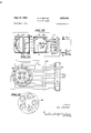
- Figure 1 illustrates the invention as applied to a lock actuating device
- Figure 2 is a schematic drawing of one possible set of circuit connections for the photoelectric cells of Figure 1;
- Figure 3 shows a keying device for use with the circuit of Figure 2;
- Figure 4 is a chart of the several possible connections of the three photoelectric cells of Figure 1;
- Figure 5 is a schematic drawing showing switching ice means for obtaining the different connections charted in Figure 4;
- FIG. 6 is a schematic illustration of another embodiment of the invention.
- Figures 7 and 8 illustrate means for obtaining bandpass and band-elimination elements for use in Figure 6;
- Figure 9 is a graph of spectral band filters
- Figures 10 and 11 illustrate apparatus using the spectral band filters of Figure 9 to obtain band-pass and bandelimination elements
- Figure 12 illustrates a remote operating system operative in response to predetermined hues only
- Figure 13 is a sectional view taken along lines 1313 or 13-13' of Figure 12, and
- Figure 14 is a modification of the arrangement: of the invention illustrated in Figure 12.
- the invention is illustrated as applied to the locking of the door 10 to the door frame 12.
- the bolt 14 is withdrawn from latch 16 upon energization of coil 18 by battery 20 and the connections made in the switching box 22.
- Connected to the switching box are three light sensitive means such as photoelectric cells A, B and C, each cell being responsive to light from respective light sources such as bulbs 24, 26 and 28 when their path of light is not obstructed.
- a keying device such as key 30 may be inserted through the door 10 so as to determine which of the light sources 24, 26, 28 illuminates its respective photoelectric cell.
- the light sources may be connected in series or in parallel directly across a source of energy such as battery 32 or through a switch 34 to said source of energy. When switch 34 is used, it is disposed in such a manner that key 30, when inserted, will close the switch.
- the photoelectric cells A, B and C may be connected either in series or parallel with a load and as such will determine whether or not the load will receive current. For example, if a photoelectric cell is connected in series with the load, it is evident that the cell must conduct current as upon the receipt of light before its load will receive current. Likewise, if a cell is connected across the load, conduction of current through the cell reduces the amount of current through the load. In this invention it is assumed that the load is adjusted such that it will not operate upon a reduction of current therethrough as by part of the current being conducted through a photoelectric cell in parallel with the load.
- Figure 2 illustrates the preceding by the connection of photoelectric cells B and C in series with a load such as relay coil 36.
- a key 30' as illustrated in Figure 3 is used.
- blank 50 were an aperture, or either apertures 46, 48 were blanks, insufficient current would be conveyed to coil 36.
- the photoelectric cells are preferably connected so that there will also be one cell in parallel with the load and one cell in series with the load. In this manner a key composed of all apertures could never operate the system, nor could a key composed of all blanks operate the system.
- Figure 4 shows a chart of the different photoelectric connections for three cells A, B, C with P and S in the chart referring to parallel and seria connection respectively.
- Line 1 of the chart represents the situation as depicted in Figure 2.
- both photoelectric cells A and B are in parallel while photoelectric cell C is in series with the load.
- Line 3 shows another combination in which photoelectric cells A and C are in parallel with each other and with the load while only cell B is in series with the load.
- Lines 4, 5 and 6 likewise show other combinations which may be used. Lines 7 and 8, however, should not be used since, as explained above, all holes or all blanks in the key would operate the cells when connected in accordance with lines 7 and 8 respectively, which situation would provide an easily pickable lock.
- a switching system such as the one contained within dotted line 52 of Figure 5 may be used in the switching box 22 of Figure 1.
- photoelectric cells A, B and C are connected through a six-pole, six-position switch to a relay coil 36, battery 38 and variable resistor 40 to operate switch 42 connected in lines 44.
- Each lead from the different photoelectric cells A, B, C is connected to a different pole of the switch 54 and the six different poles 56, 57, 58, 59, 60 and 61 are mechanically connected as shown by dotted line 62 for movement together around the six different terminal positions, numbered counterclockwise 1 through 6 for convenience, for each pole.
- a variety of colors of light or hues may be utilized for keying the device.
- two photoelectric elements are used together in a manner such that one element is constructed so that the photoelectric cell in the element responds only to a given hue, while the cell of the second element is arranged in the element to respond to all hues except said given hue, then the combination of the two photoelectric elements, if the former be connected in series and the latter in parallel with the load, will operate to actuate the load only if a single hue and no other hue is present.
- a photoelectric element of the first type may be termed a narrow band pass filter element while a photoelectric element of the second type may be referred to as a narrow band elimination filter element.
- Figure 6 illustrates three sets 70, 72 and 74 of band-pass and band-elimination filter elements P and E P and E and P and E respectively.
- the band-pass elements P P and P are in series with the load coil 36, battery 38 and variable resistor 40, while the band-elimination elements E E and B are in parallel with the load 36.
- any other hues incident upon the photoelectric elements will cause insufficient current to coil 36.
- element P were set to be responsive to the wavelengths of red light while E was set to be responsive to all wavelengths of light except red, and elements P and E were similarly set to wavelengths of blue light, and elements P E to wavelengths of green light, sufficient operating current would pass through coil 36 if light rays of wavelengths corresponding to the hues red, blue and green only were present respectively upon the different sets of paslimination elements.
- FIGs 7 and 8 illustrate band-pass and band-elimination elements respectively as accomplished by use of a prism 100.
- White light from source 102 may be passed through a slit in mask 104 to be incident upon one side of prism 100.
- the white light is refracted through the prism to produce a dispersion of the light beam into its component colors, the six principal ones of which (red, orange, yellow, green, blue and violet) are indicated in Figures 7 and 8 by the emerging rays R. O. Y. G, B and V respectively.
- the photoelectric cell P is placed so as to intercept only one of the color rays, for example, the yellow ray.
- a mask 106 may be used so that cell P is assured of being responsive only to a desired narrow band.
- the rays emerging from prism as shown in Figure 8 are subjected to a lens 108. All the rays except that which is to be eliminated are passed through the lens and focused on photoelectric cell E. The band of wavelengths which is to be eliminated is rejected by the lens. This is accomplished by blackening or masking the lens in the area thereon where the wavelengths to be eliminated would naturally fall incident on the lens. For example, to reject wavelengths of yellow light, the area 116 is darkened so that yellow light waves will not pass through the lens.
- the form shown in Figure 10 may be used.
- white light from source 102 may be made incident upon filter d which corresponds to curve d of Figure 9. Assuming this filter to pass only blue light, the photoelectric cell P will receive no light except that in the blue light range.
- Figure 11 illustrates the method of forming a bandelimination element.
- the face plate 120 of the container 122 is opaque except for the fifteen circular shaped filters therein,'designated a, b, c, e, f, etc., through 2 in correspondence, with the respective curves of Fig- .ure 9, It should be'noted that a filter d is not placed in the face plate 1231. Therefore, white light from source 102 will pass all light wavelengths except the wavelengths represented by the absent filter d which, as in the examples illustrated in Figure 10, represents blue light wavelengths. Photoelectric cell B provides a signal, then, only when light other than that having a wavelength in the blue light range is received.
- FIG 12 there is an embodiment shown which utilizes band-pass filtering elements as well as band-elimination elements with the individual filters therein being of the type illustrated in Figure 9.
- the apparatus of Figure 12 may be used in many dilferent ways and is particularly useful as a remote control system.
- a light source 102 is held in casing 150 by reilector 152.
- An array of color filters disposed in a manner such as that shown in Figure 13.
- the filter holder 154 is opaque except for the areas including the different color filters a, c, 'e, g and i.
- these particular filters correspond to the curves therein designated a, c, e, g and i, respectively.
- light will emerge from holder 154 and pass through lens 156 in color corresponding to the filters in the holder 154.
- the light flux may be received after passage through a transparent or translucent window or lens 158 which is held in a suitable manner in casing 160.
- a semi-transmitting mirror 162 preferably spherical in shape, which passes a part of the light and reflects a part. For example, it may pass nearly 50 percent of every wavelength of light flux, while reflecting a similar amount of every wavelength of light received.
- the flux which is passed directly through mirror 162 is received by a second array of color filters disposed in holder 164.
- the filters in holder 164 are identical with those in holder 154 and may be arranged in a manner similar to that shown in Figure 13. However, rotational displacement of the filters in holder 164 is immaterial, and the filters therein need not be aligned with the respective filters in holder 154.
- Behind each filter in holder 164 is a photoelectric cell 166 disposed to receive light only from its respective filter. These photoelectric cells are connected in series with each other and with the relay coil 36, battery 33 and variable resistor 40 in the manner heretofore described, so that when light is incident upon each or" the cells 166 simultaneously, current will flow in coil 36 to operate switch 42 and close the circuit containing lines 44.
- the light flux which is received by mirror 162 but reflected thereby is directed toward photoelectric cell 168. However, all of the light reflected thereby will not necessarily be incident upon cell 168 since there is an array of light filters in front of the cell.
- This third array of filters is disposed in holder 170' which is connected to the radial light bafile 172 attached to the front of cell 168.
- the filters in holder 170 are arranged in a circular manner like those illustrated in Figure 13, but correspond in wavelength transmission to curves [1, d, f, h and j of Figure 9.
- these filters are disposed in holder 170 in a circle concentric with, but smaller than, the circle upon which the centers of the filters in holder 164 are preferably located.
- the radial lines upon which the third array of filters lies is rotated slightly with respect to the second array so that, in a longitudinal view of casing 160 wherein the two array holders appear superimposed, the radial lines of the two arrays combined containing filters representing-curves a through p do not overlap but are adjacent successively and progressively in increasing order of wavelengths.
- this is a preferred arrangement; however, limitation thereto is not desired since the second and third arrays may be positionally rotated or otherwise disposed with a workable result obtained.
- wavelengths of light which are meant to cause operation of switch 42, do not fall on photoelectric cell 168. However, if light other than the wavelengths meant to operate the switch are present, current will pass through photoelectric cell 168 and reduce the current in coil 36 so that switch 42 is not operated.
- Thesystem may be further complicated by polarization of the light incident upon the semi-transparent mirror 162. This maybe accomplished by polarizing lens 158 and making it rotatable as indicated at 174 with respect to the remainder .of .the casing (including the two arrays of color filters therein). To provide the correct combination the remote control unit must compensate for the polarizing produced by lens 158. Therefore, lens 156 may be polarized and rotatable in respect to the remainder .of the case as indicated at '176. In this manner the person operating the remote control unit must not only have the correct combination of light filtering elements, but must also polarize the emerging light tothe proper degree before switch 42 will be operated.
- vA modification of the apparatus shown in Figure 12 may comprise the use of a filtering array containing filters of each of the sixteen different spectral bands indicated in Figure 9.
- mirror 162 and the photoelectric cell arrangement 168 and filter holder 17th may be removed from the casing 160.
- a "holder is opaque except for the circular areas designated a through p, these areas corresponding to the respective filters and their bands as illustrated in Figure 9.
- Each filter a through p has located adjacent thereto a photoelectric cell so that any light passing through the filter will actuate the photoelectric cell.
- the cells may be each connected as by wires 182 to a switch box 22' (similar to the switching arrangement shown in Figure 5.) so that the photoelectric cells may each be connected either in series or parallel with the load. In this manner numerous combinations may be obtained and the combination may be changed from day to day.
- light source means and a remote unit for receiving the light from said means, said light means including means for providing light therefrom in a variety of predetermined colors, said remote unit comprising light sensitive means in number equaling said variety of predetermined colors and each including means causing response to a different one of said variety of colors, photoelectric means responsive to a second variety of predetermined colors not including any color of the first mentioned variety of predetermined colors, circuit means including an actuable load and a source of energy, means coupling said light sensitive means in series with the load and coupling said photo electricmeans in parallel with the load, the arrangement being such that the load is actuated only when said first mentioned variety of predetermined colors is received by said remote unit, other colors of light being operative to cause the photoelectric means to prevent actuation of said load.
- each light sensitive means includes a spectral band filter corresponding to a different color in the first mentioned variety of colors.
- the remote light receiving unit includes means for transmitting a predetermined amount of the light incident thereupon and for reflecting a predetermined amount of said light, and wherein the reflected light is received by said photoelectric means, while the transmitted light is received by said light sensitive means.
- Apparatus as in claim 3 wherein the means for transmitting and reflecting light incident thereupon is a semi-transparent reflecting surface disposed between said light sensitive means and photoelectric means.
- Apparatus as in claim 4 wherein the photoelectric means includes a spectral band filter for each color in said second variety of colors and wherein each light' sensitive means includes a spectral band filter different than that for another light sensitive means and different than the filters for said photoelectric means.
- spectral band filters for the light sensitive means are disposed in an increasing wavelength configuration while the filters for the photoelectric means are disposed in like manner, the arrangement being such that a beam of light having a wavelength band width larger than necessary to cause response by one of said light sensitive means prohibits actuation of said load by response to a portion of said band width by the photoelectric means.
- a plurality of light sensitive means each responsive respectively to predetermined wavelengths of light
- circuit means including an actuatable load and a source of energy
- connection means coupling each of said light sensitive means in a predetermined manner to said circuit means including means connecting at least one of said light sensitive means in parallel with both said load and energy source for diverting the current of said source from said load and consequently preventing actuation thereof when said one light sensitive means is receiving wavelengths of light to which it is responsive
- said connection means further including means connecting at least one other of the light sensitive means in series with both said load and energy source for passing the current of said source to said load and allowing consequent actuation thereof only when each series connected light sensitive means receives wavelengths of light to which each is responsive if at the same time each parallel connected light sensitive means does not receive wavelengths of light to which each is respectively responsive, and further comprising means including light source means to cause actuation of said load
- the load actuating means comprises an opaque member having light transmitting means therein for each of said serially connected light
- a plurality of light sensitive means each responsive respectively to predetermined wavelengths of light
- circuit means including an actuatable load and a source of energy
- connection means coupling each of said light sensitive means in a predetermined manner to said circuit means including means connecting at least one of said light sensitive means in parallel with both said load and energy source for diverting the current of said source from said load and consequently preventing actuation thereof when said one light sensitive means is receiving wavelengths of light'to which it is responsive
- said connection means further including means connecting at least one other of the light sensitive means in series with both said load and energy source for passing the current of said source to said load and allowing consequent actuation thereof only when each series connected light sensitive means receives wavelengths o-f light to which each is responsive if at the same time each parallel connected light sensitive means does not receive wavelengths of light to which each is respectively responsive, and further comprising means including light source means to cause actuation of said load, wherein said light source means includes a different source of light associated with each of the light sensitive means, and
- a plurality of light sensitive means each responsive respectively to predetermined wavelengths of light
- circuit means including an actuatable load and a source of energy
- connection means coupling each of said light sensitive means in a predetermined manner to said circuit means including means connccting at least one of said light sensitive means in parallel with both said load and energy source for diverting the current of said source from said load and consequently preventing actuation thereof when said one light sensitive means is receiving wavelengths of light to which it is responsive
- said connection means further including means connecting at least one other of the light sensitive means in series with both said load and energy source for passing the current of said source to said load and allowing consequent actuation thereof only when each series connected light sensitive means receives wavelengths of light to which each is responsive if at the same time each parallel connected light sensitive means does not receive wavelengths of light to which each is respectively responsive, and further comprising means including light source means to cause actuation of said load, wherein the load actuating means includes light transmitting means for each of said serially connected light sensitive means
- the light transmitting means and the light prohibiting means includes prismatic means for dispersion of the light into component hues, the light prohibiting means further including means in the path of said component hues to eliminate the wavelengths to which the serially connected light sensitive means responds.
- said light sensitive means are divided into sets, each set including a light sensitive means connected in series with the load and another light sensitive means connected in parallel with the load and responding to different wavelengths of light, the serially connected means being responsive to actuate said load upon receipt of said different wavelengths respectively if the parallel connected means ICCClVG light containing only the same wavelengths respectively.
Landscapes
- Spectrometry And Color Measurement (AREA)
Description
Sept. 20, 1960 H. c. BECKER ACTUATING SYSTEM 4 Sheets-Sheet 1 Filed May 9. 1956 CHART OF P E CONNECTIONS *s SERIES P IPARA LLEL INVENTOR HAL C. BECKER TRANSMISSION Sept. 20, 1960 H. c. BECKER 2,953,589
ACTUATING SYSTEM Filed May-9. 1956 4 Sheets-Sheet 2 h l .1 k l N O O WAVE LENGTH m U INVENTOR HAL C. BECKER ATTORNEYS Sept. 20, 1960 H. c. BECKER 2,953,639
ACTUATING SYSTEM Filed May 9. 1956 4 Sheets-Sheet 5 FIG] INVENTOR HA L C. B ECK E R ATTQRNEY$ Sept. 20, 1960 Filed May 9. 1956 H. C. BECKER ACTUATING SYSTEM 4 Sheets-Sheet 4 INVENTOR HA L c. as CKE R ATTORNEYS United States Patent ACTUATING SYSTEM Hal C. Becker, New Orleans, La., assignor to Precou Process and Equipment Corporation, New Orleans, La., a corporation of Louisiana Filed May 9, 1956, Ser. No. 583,875
12 Claims. (Cl. 250-209) This invention relates to a photoelectric actuating system and in particular to the operating of a device, whether 1remote or near, -by use of either white light or colored ight.
In the past photoelectric actuating systems have been designed to open or close circuits connected to doors or the like. However, such systems are not foolproof since by the connections of the photoelectric cells such systems may be operated by the presence of light on all cells or the absence of light on all cells.
Therefore, it is the primary object of this invention to provide apparatus responsive to light in. a foolproof manner.
It is another object of this invention to provide apparatus including light sensitive means connected so as to be responsive neither to the absence of light nor the presence of light on all the light sensitive means.
It is a further object of this invention to provide photoelectric actuating apparatus wherein the photoelectric cells are connected at least one in parallel and one in series with the load to be actuated.
It is still another object of this invention to provide photoelectric cells in sets of two, each set having one cell connected in series with the load to be actuated and the other cell connected in parallel with the load, and each set being responsive to a different wavelength of light.
Another object of the invention, in combination with the preceding object, is to provide prismatic means for operating each set of photoelectric cells.
Still another object of the invention is to provide apparatus including narrow spectral band filters by which a narrow band of wavelengths of light may be operative to cause current conduction in a photoelectric cell in series with a load to be actuated and by which a narrow band of light may be eliminated or prohibited from reaching a photoelectric cell connected in parallel with said load.
Another object of the invention is to provide remote control apparatus for operating a light sensitive unit, the unit being operative upon receipt of only predetermined colors of light.
Other objects and the entire scope of the invention will become further apparent from the following detailed description of the exemplary embodiments of the various phases and aspects of the invention.
The exemplary arrangements according to the invention may be best understood with reference to the accompanying drawings, wherein:
Figure 1 illustrates the invention as applied to a lock actuating device;
Figure 2 is a schematic drawing of one possible set of circuit connections for the photoelectric cells of Figure 1;
Figure 3 shows a keying device for use with the circuit of Figure 2;
Figure 4 is a chart of the several possible connections of the three photoelectric cells of Figure 1;
Figure 5 is a schematic drawing showing switching ice means for obtaining the different connections charted in Figure 4;
Figure 6 is a schematic illustration of another embodiment of the invention;
Figures 7 and 8 illustrate means for obtaining bandpass and band-elimination elements for use in Figure 6;
Figure 9 is a graph of spectral band filters;
Figures 10 and 11 illustrate apparatus using the spectral band filters of Figure 9 to obtain band-pass and bandelimination elements;
Figure 12 illustrates a remote operating system operative in response to predetermined hues only;
Figure 13 is a sectional view taken along lines 1313 or 13-13' of Figure 12, and
Figure 14 is a modification of the arrangement: of the invention illustrated in Figure 12.
The invention will be described in reference particularly to the use thereof in a locking device. However, it will be apparent to those skilled in the art upon reading this specification that the invention may be employed in many different ways, and is not to be limited to lock actuating devices.
In Figure 1, the invention is illustrated as applied to the locking of the door 10 to the door frame 12. The bolt 14 is withdrawn from latch 16 upon energization of coil 18 by battery 20 and the connections made in the switching box 22. Connected to the switching box are three light sensitive means such as photoelectric cells A, B and C, each cell being responsive to light from respective light sources such as bulbs 24, 26 and 28 when their path of light is not obstructed. In this invention a keying device such as key 30 may be inserted through the door 10 so as to determine which of the light sources 24, 26, 28 illuminates its respective photoelectric cell. The light sources may be connected in series or in parallel directly across a source of energy such as battery 32 or through a switch 34 to said source of energy. When switch 34 is used, it is disposed in such a manner that key 30, when inserted, will close the switch.
The photoelectric cells A, B and C may be connected either in series or parallel with a load and as such will determine whether or not the load will receive current. For example, if a photoelectric cell is connected in series with the load, it is evident that the cell must conduct current as upon the receipt of light before its load will receive current. Likewise, if a cell is connected across the load, conduction of current through the cell reduces the amount of current through the load. In this invention it is assumed that the load is adjusted such that it will not operate upon a reduction of current therethrough as by part of the current being conducted through a photoelectric cell in parallel with the load. Figure 2 illustrates the preceding by the connection of photoelectric cells B and C in series with a load such as relay coil 36. When current is caused to conduct through both photoelectric cells B and C from battery 38 and variable resistor 46, the current through coil 36 is sufficient to close the relay switch 42 to allow current to flow in lines 44. The preceding is true only if no current flows through photoelectric cell A, since current therethrough will reduce the current through coil 36 and prevent the closing of switch 42. In that case, lines 44 will not carry current from battery 20 (Figure 1) to actuate bolt 14. Those skilled in the art will recognize that coil 36 may, instead of actuating switch 42, operate to control bolt 14 directly so that the intervening circuitry including battery 20 is unessential.
To operate a system as shown in Figure 2, a key 30' as illustrated in Figure 3 is used. The insertion of key 30' between light sources 24, 26 and 28 and photoelectric cells A, B and C with the latter being connected as shown in Figure 2, so that the apertures 46 and 48 allow light from sources 26 and 28 to cells B and C respectively, while blank 50 prevents light from source 24 to cell A, allows full energization of coil 36. However, if blank 50 were an aperture, or either apertures 46, 48 were blanks, insufficient current would be conveyed to coil 36.
The photoelectric cells are preferably connected so that there will also be one cell in parallel with the load and one cell in series with the load. In this manner a key composed of all apertures could never operate the system, nor could a key composed of all blanks operate the system. With three photoelectric cells, eight different combinations of connections may be obtained. Figure 4 shows a chart of the different photoelectric connections for three cells A, B, C with P and S in the chart referring to parallel and seria connection respectively. Line 1 of the chart represents the situation as depicted in Figure 2. In line 2, both photoelectric cells A and B are in parallel while photoelectric cell C is in series with the load. Line 3 shows another combination in which photoelectric cells A and C are in parallel with each other and with the load while only cell B is in series with the load. Lines 4, 5 and 6 likewise show other combinations which may be used. Lines 7 and 8, however, should not be used since, as explained above, all holes or all blanks in the key would operate the cells when connected in accordance with lines 7 and 8 respectively, which situation would provide an easily pickable lock.
To obtain the different connections illustrated in the chart of Figure 4, a switching system such as the one contained within dotted line 52 of Figure 5 may be used in the switching box 22 of Figure 1. In Figure 5, photoelectric cells A, B and C are connected through a six-pole, six-position switch to a relay coil 36, battery 38 and variable resistor 40 to operate switch 42 connected in lines 44. Each lead from the different photoelectric cells A, B, C is connected to a different pole of the switch 54 and the six different poles 56, 57, 58, 59, 60 and 61 are mechanically connected as shown by dotted line 62 for movement together around the six different terminal positions, numbered counterclockwise 1 through 6 for convenience, for each pole. When the poles are in their top position, i.e., position 1, the connections of cells A, B and C correspond to line 1 of chart 4; when in position 2, i.e., the first position counterclockwise from the top terminal position, the cells are connected in accordance with line 2 of the chart of Figure 4; when in position 3, the cells are connected as illustrated for line 3 of Figure 4; etc. In this manner, six different combinations may be readily obtained so that it will be necessary for the person desiring to operate the system to use the proper and corresponding key before he may acquire access through the locked door.
To further complicate the system, a variety of colors of light or hues may be utilized for keying the device. For example, if two photoelectric elements are used together in a manner such that one element is constructed so that the photoelectric cell in the element responds only to a given hue, while the cell of the second element is arranged in the element to respond to all hues except said given hue, then the combination of the two photoelectric elements, if the former be connected in series and the latter in parallel with the load, will operate to actuate the load only if a single hue and no other hue is present. A photoelectric element of the first type may be termed a narrow band pass filter element while a photoelectric element of the second type may be referred to as a narrow band elimination filter element. Figure 6 illustrates three sets 70, 72 and 74 of band-pass and band-elimination filter elements P and E P and E and P and E respectively. The band-pass elements P P and P are in series with the load coil 36, battery 38 and variable resistor 40, while the band-elimination elements E E and B are in parallel with the load 36.
Therefore, assuming each of the three sets of elements to be responsive to a different hue, any other hues incident upon the photoelectric elements will cause insufficient current to coil 36. For example, if element P were set to be responsive to the wavelengths of red light while E was set to be responsive to all wavelengths of light except red, and elements P and E were similarly set to wavelengths of blue light, and elements P E to wavelengths of green light, sufficient operating current would pass through coil 36 if light rays of wavelengths corresponding to the hues red, blue and green only were present respectively upon the different sets of passelimination elements.
Pass and elimination light filtering elements of the type described in the preceding paragraph may be constructed in several different forms. Figures 7 and 8 illustrate band-pass and band-elimination elements respectively as accomplished by use of a prism 100. White light from source 102 may be passed through a slit in mask 104 to be incident upon one side of prism 100. As is well known, the white light is refracted through the prism to produce a dispersion of the light beam into its component colors, the six principal ones of which (red, orange, yellow, green, blue and violet) are indicated in Figures 7 and 8 by the emerging rays R. O. Y. G, B and V respectively. In Figure 7, the photoelectric cell P is placed so as to intercept only one of the color rays, for example, the yellow ray. For greater accuracy, a mask 106 may be used so that cell P is assured of being responsive only to a desired narrow band.
To form a band-elimination element, the rays emerging from prism as shown in Figure 8 are subjected to a lens 108. All the rays except that which is to be eliminated are passed through the lens and focused on photoelectric cell E. The band of wavelengths which is to be eliminated is rejected by the lens. This is accomplished by blackening or masking the lens in the area thereon where the wavelengths to be eliminated would naturally fall incident on the lens. For example, to reject wavelengths of yellow light, the area 116 is darkened so that yellow light waves will not pass through the lens.
In a manner similar to the production of band-pass and band-elimination elements through prisms as above described, it will now be apparent to those skilled in the art that similar elements may be made by use of the well known process of diffraction grating.
Additional ways of making band-pass and band-elimination elements are possible by the use of the commercially available interference filters for isolating narrow spectral bands. In Figure 9 there is reproduced a chart showing the wavelength range of sixteen different spectral filters now commercially available. The wavelength is given in millimicrons and is plotted against the percent transmission of light for the different filters. It should be noted that the spectral width of each of the different filters is narrow and that they do not overlap at 30% transmission or above. For identifying purposes, each different filter as represented by the different curves and their peaks in the chart of Figure 9 is as designated respectively a, b, c, d, etc., as may be noted at the top of the chart.
To make a band-pass element from one of the filters charted in Figure 9, the form shown in Figure 10 may be used. For example, white light from source 102 may be made incident upon filter d which corresponds to curve d of Figure 9. Assuming this filter to pass only blue light, the photoelectric cell P will receive no light except that in the blue light range.
Figure 11 illustrates the method of forming a bandelimination element. The face plate 120 of the container 122 is opaque except for the fifteen circular shaped filters therein,'designated a, b, c, e, f, etc., through 2 in correspondence, with the respective curves of Fig- .ure 9, It should be'noted that a filter d is not placed in the face plate 1231. Therefore, white light from source 102 will pass all light wavelengths except the wavelengths represented by the absent filter d which, as in the examples illustrated in Figure 10, represents blue light wavelengths. Photoelectric cell B provides a signal, then, only when light other than that having a wavelength in the blue light range is received.
Referring now to Figure 12, there is an embodiment shown which utilizes band-pass filtering elements as well as band-elimination elements with the individual filters therein being of the type illustrated in Figure 9. The apparatus of Figure 12 may be used in many dilferent ways and is particularly useful as a remote control system. A light source 102 is held in casing 150 by reilector 152. In front of the reflector and light source is an array of color filters disposed in a manner such as that shown in Figure 13. The filter holder 154 is opaque except for the areas including the different color filters a, c, 'e, g and i. With reference back to Figure 9, these particular filters correspond to the curves therein designated a, c, e, g and i, respectively. Therefore, light will emerge from holder 154 and pass through lens 156 in color corresponding to the filters in the holder 154. At a remote location the light flux may be received after passage through a transparent or translucent window or lens 158 which is held in a suitable manner in casing 160. Further within casing 160 is a semi-transmitting mirror 162, preferably spherical in shape, which passes a part of the light and reflects a part. For example, it may pass nearly 50 percent of every wavelength of light flux, while reflecting a similar amount of every wavelength of light received. The flux which is passed directly through mirror 162 is received by a second array of color filters disposed in holder 164. The filters in holder 164 are identical with those in holder 154 and may be arranged in a manner similar to that shown in Figure 13. However, rotational displacement of the filters in holder 164 is immaterial, and the filters therein need not be aligned with the respective filters in holder 154. Behind each filter in holder 164 is a photoelectric cell 166 disposed to receive light only from its respective filter. These photoelectric cells are connected in series with each other and with the relay coil 36, battery 33 and variable resistor 40 in the manner heretofore described, so that when light is incident upon each or" the cells 166 simultaneously, current will flow in coil 36 to operate switch 42 and close the circuit containing lines 44.
The light flux which is received by mirror 162 but reflected thereby is directed toward photoelectric cell 168. However, all of the light reflected thereby will not necessarily be incident upon cell 168 since there is an array of light filters in front of the cell. This third array of filters is disposed in holder 170' which is connected to the radial light bafile 172 attached to the front of cell 168. The filters in holder 170 are arranged in a circular manner like those illustrated in Figure 13, but correspond in wavelength transmission to curves [1, d, f, h and j of Figure 9. Preferably, these filters are disposed in holder 170 in a circle concentric with, but smaller than, the circle upon which the centers of the filters in holder 164 are preferably located. However, the radial lines upon which the third array of filters lies is rotated slightly with respect to the second array so that, in a longitudinal view of casing 160 wherein the two array holders appear superimposed, the radial lines of the two arrays combined containing filters representing-curves a through p do not overlap but are adjacent successively and progressively in increasing order of wavelengths. As indicated above, this is a preferred arrangement; however, limitation thereto is not desired since the second and third arrays may be positionally rotated or otherwise disposed with a workable result obtained. In either of these manners wavelengths of light Which are meant to cause operation of switch 42, do not fall on photoelectric cell 168. However, if light other than the wavelengths meant to operate the switch are present, current will pass through photoelectric cell 168 and reduce the current in coil 36 so that switch 42 is not operated.
Thesystemmay be further complicated by polarization of the light incident upon the semi-transparent mirror 162. This maybe accomplished by polarizing lens 158 and making it rotatable as indicated at 174 with respect to the remainder .of .the casing (including the two arrays of color filters therein). To provide the correct combination the remote control unit must compensate for the polarizing produced by lens 158. Therefore, lens 156 may be polarized and rotatable in respect to the remainder .of the case as indicated at '176. In this manner the person operating the remote control unit must not only have the correct combination of light filtering elements, but must also polarize the emerging light tothe proper degree before switch 42 will be operated.
vA modification of the apparatus shown in Figure 12 may comprise the use of a filtering array containing filters of each of the sixteen different spectral bands indicated in Figure 9. In this manner, mirror 162 and the photoelectric cell arrangement 168 and filter holder 17th may be removed from the casing 160. In this modification a "holder is opaque except for the circular areas designated a through p, these areas corresponding to the respective filters and their bands as illustrated in Figure 9. 'Each filter a through p has located adjacent thereto a photoelectric cell so that any light passing through the filter will actuate the photoelectric cell. The cells may be each connected as by wires 182 to a switch box 22' (similar to the switching arrangement shown in Figure 5.) so that the photoelectric cells may each be connected either in series or parallel with the load. In this manner numerous combinations may be obtained and the combination may be changed from day to day.
Although the foregoing description has been in particular with relation to lock type devices, it will be found useful in various forms in light identification purposes and particularly in secret communication via light beam or in IFF operations.
Thus, it is apparent that there is provided by this invention a construction in which the various phases, objects and advantages hereinbefore set forth, inter alia, are successfully achieved.
Modifications of this invention now described herein will become apparent to those skilled in the art. Therefore, it is intended that the matter contained in the foregoing description and accompanying drawings be interpreted as illustrative and not :limitative, the scope of the invention being defined in the appended claims.
What is claimed is:
1. In a photoelectric actuating system, light source means and a remote unit for receiving the light from said means, said light means including means for providing light therefrom in a variety of predetermined colors, said remote unit comprising light sensitive means in number equaling said variety of predetermined colors and each including means causing response to a different one of said variety of colors, photoelectric means responsive to a second variety of predetermined colors not including any color of the first mentioned variety of predetermined colors, circuit means including an actuable load and a source of energy, means coupling said light sensitive means in series with the load and coupling said photo electricmeans in parallel with the load, the arrangement being such that the load is actuated only when said first mentioned variety of predetermined colors is received by said remote unit, other colors of light being operative to cause the photoelectric means to prevent actuation of said load.
2. Apparatus as in claim 1 wherein said photoelectric means includes a spectral band filter for each color in said second variety and wherein each light sensitive means includes a spectral band filter corresponding to a different color in the first mentioned variety of colors.
3. Apparatus as in claim 1 wherein the remote light receiving unit includes means for transmitting a predetermined amount of the light incident thereupon and for reflecting a predetermined amount of said light, and wherein the reflected light is received by said photoelectric means, while the transmitted light is received by said light sensitive means.
4. Apparatus as in claim 3 wherein the means for transmitting and reflecting light incident thereupon is a semi-transparent reflecting surface disposed between said light sensitive means and photoelectric means.
5. Apparatus as in claim 4 wherein the photoelectric means includes a spectral band filter for each color in said second variety of colors and wherein each light' sensitive means includes a spectral band filter different than that for another light sensitive means and different than the filters for said photoelectric means.
6. Apparatus as in claim 5 wherein the spectral band filters for the light sensitive means are disposed in an increasing wavelength configuration while the filters for the photoelectric means are disposed in like manner, the arrangement being such that a beam of light having a wavelength band width larger than necessary to cause response by one of said light sensitive means prohibits actuation of said load by response to a portion of said band width by the photoelectric means.
7. In an actuating system, a plurality of light sensitive means each responsive respectively to predetermined wavelengths of light, circuit means including an actuatable load and a source of energy, and connection means coupling each of said light sensitive means in a predetermined manner to said circuit means including means connecting at least one of said light sensitive means in parallel with both said load and energy source for diverting the current of said source from said load and consequently preventing actuation thereof when said one light sensitive means is receiving wavelengths of light to which it is responsive, said connection means further including means connecting at least one other of the light sensitive means in series with both said load and energy source for passing the current of said source to said load and allowing consequent actuation thereof only when each series connected light sensitive means receives wavelengths of light to which each is responsive if at the same time each parallel connected light sensitive means does not receive wavelengths of light to which each is respectively responsive, and further comprising means including light source means to cause actuation of said load, wherein the load actuating means comprises an opaque member having light transmitting means therein for each of said serially connected light sensitive means to permit response thereof to the associated predetermined wavelengths of light.
8. In an actuating system, a plurality of light sensitive means each responsive respectively to predetermined wavelengths of light, circuit means including an actuatable load and a source of energy, and connection means coupling each of said light sensitive means in a predetermined manner to said circuit means including means connecting at least one of said light sensitive means in parallel with both said load and energy source for diverting the current of said source from said load and consequently preventing actuation thereof when said one light sensitive means is receiving wavelengths of light'to which it is responsive, said connection means further including means connecting at least one other of the light sensitive means in series with both said load and energy source for passing the current of said source to said load and allowing consequent actuation thereof only when each series connected light sensitive means receives wavelengths o-f light to which each is responsive if at the same time each parallel connected light sensitive means does not receive wavelengths of light to which each is respectively responsive, and further comprising means including light source means to cause actuation of said load, wherein said light source means includes a different source of light associated with each of the light sensitive means, and wherein the load actuating means includes an opaque member having light transmitting means therein aligned only with each series connected light sensitive means and its respective light source.
9. In an actuating system, a plurality of light sensitive means each responsive respectively to predetermined wavelengths of light, circuit means including an actuatable load and a source of energy, and connection means coupling each of said light sensitive means in a predetermined manner to said circuit means including means connccting at least one of said light sensitive means in parallel with both said load and energy source for diverting the current of said source from said load and consequently preventing actuation thereof when said one light sensitive means is receiving wavelengths of light to which it is responsive, said connection means further including means connecting at least one other of the light sensitive means in series with both said load and energy source for passing the current of said source to said load and allowing consequent actuation thereof only when each series connected light sensitive means receives wavelengths of light to which each is responsive if at the same time each parallel connected light sensitive means does not receive wavelengths of light to which each is respectively responsive, and further comprising means including light source means to cause actuation of said load, wherein the load actuating means includes light transmitting means for each of said serially connected light sensitive means for transmitting thereto the predetermined wavelengths of light to which same are respectively responsive and means to prohibit receipt by the parallel connected light sensitive means of the light wavelengths to which the serially connected light sensitive means respond.
10. Apparatus as in claim 9 wherein the light transmitting means and the light prohibiting means includes prismatic means for dispersion of the light into component hues, the light prohibiting means further including means in the path of said component hues to eliminate the wavelengths to which the serially connected light sensitive means responds.
11. Apparatus as in claim 9 wherein the light transmitting means includes a different spectral band filter for producing each of said predetermined wavelengths of light for the serially connected light sensitive means and wherein the light prohibiting means includes other different spectral band filters for producing each of said predetermined wavelengths of light for the parallel connected light sensitive means.
12. Apparatus as in claim 9 wherein said light sensitive means are divided into sets, each set including a light sensitive means connected in series with the load and another light sensitive means connected in parallel with the load and responding to different wavelengths of light, the serially connected means being responsive to actuate said load upon receipt of said different wavelengths respectively if the parallel connected means ICCClVG light containing only the same wavelengths respectively.
References Cited in the file of this patent UNITED STATES PATENTS 1,727,930 Bock Sept. 10, 1929 1,911,986 Bischolf May 30, 1933 1,992,869 Krell Feb. 26, 1935 2,008,150 Nelson July 16, 1935 2,041,079 Lyle May 19, 1936 2,497,405 Glover Feb. 14, 1950 FOREIGN PATENTS 51,547 France June 29, 1942 (Addition to Patent 826,030)
Priority Applications (1)
| Application Number | Priority Date | Filing Date | Title |
|---|---|---|---|
| US583875A US2953689A (en) | 1956-05-09 | 1956-05-09 | Actuating system |
Applications Claiming Priority (1)
| Application Number | Priority Date | Filing Date | Title |
|---|---|---|---|
| US583875A US2953689A (en) | 1956-05-09 | 1956-05-09 | Actuating system |
Publications (1)
| Publication Number | Publication Date |
|---|---|
| US2953689A true US2953689A (en) | 1960-09-20 |
Family
ID=24334947
Family Applications (1)
| Application Number | Title | Priority Date | Filing Date |
|---|---|---|---|
| US583875A Expired - Lifetime US2953689A (en) | 1956-05-09 | 1956-05-09 | Actuating system |
Country Status (1)
| Country | Link |
|---|---|
| US (1) | US2953689A (en) |
Cited By (12)
| Publication number | Priority date | Publication date | Assignee | Title |
|---|---|---|---|---|
| US3127598A (en) * | 1960-06-30 | 1964-03-31 | Automatic Canteen Co | Currency testing apparatus |
| US3135950A (en) * | 1961-08-14 | 1964-06-02 | Sam M Finkle | Fire detecting unit |
| US3143655A (en) * | 1960-01-25 | 1964-08-04 | Malcolm W P Strandberg | Photosensitive switching device in a waveguide |
| US3205363A (en) * | 1959-08-19 | 1965-09-07 | Philips Corp | Universal photologic circuit having input luminescent elements arranged in matrix relation to output photoconductive elements with selective mask determining logic function performed |
| US3234394A (en) * | 1962-07-10 | 1966-02-08 | Kollsman Instr Corp | Angular displacement encoder with photoelectric pickoffs at different radial and angular positions |
| US3514611A (en) * | 1968-01-26 | 1970-05-26 | Intern Dryer Corp | Electrically actuated security system |
| US4015912A (en) * | 1974-03-23 | 1977-04-05 | J. Eberspacher | Electromagnetic pumping device for liquids |
| EP0153263A2 (en) * | 1984-02-20 | 1985-08-28 | Milenko Radosavljevic | Lock with optoelectronic coders |
| US4671086A (en) * | 1985-04-15 | 1987-06-09 | Protech Partnership | Redundant electrically controlled locking apparatus |
| US4686912A (en) * | 1985-04-15 | 1987-08-18 | The Protech Partnership | Electrically controlled locking apparatus and safe utilizing same |
| US5119065A (en) * | 1991-01-14 | 1992-06-02 | Wiehagen Fred A | Vehicle protection system |
| US20100054744A1 (en) * | 2008-08-31 | 2010-03-04 | Maxson Brian D | Systems and methods for detecting orientation of an optical emitter with respect to detector using oppositely polarized beams for reference |
Citations (8)
| Publication number | Priority date | Publication date | Assignee | Title |
|---|---|---|---|---|
| US1727930A (en) * | 1922-08-08 | 1929-09-10 | Bock Emil Heinrich | Safety device provided with cells which are sensitive to light |
| US1911986A (en) * | 1930-10-21 | 1933-05-30 | Zeiss Carl Fa | Receiving device for light signals |
| US1992869A (en) * | 1930-11-15 | 1935-02-26 | Krell Joseph | Selector for printing machines |
| US2008150A (en) * | 1932-03-29 | 1935-07-16 | Arthur S Nelson | Control mechanism |
| US2041079A (en) * | 1930-07-30 | 1936-05-19 | Westinghouse Electric & Mfg Co | Relay |
| FR826030A (en) * | 1936-11-23 | 1938-03-21 | Zeiss Ikon Ag | Device for photoelectric scanning of sound tracks recorded by the differential process |
| FR51547E (en) * | 1941-05-19 | 1942-10-05 | Zeiss Ikon Ag | Device for photoelectric scanning of sound tracks recorded by the differential process |
| US2497405A (en) * | 1949-03-14 | 1950-02-14 | Donald O Glover | Identification card and mechanism |
-
1956
- 1956-05-09 US US583875A patent/US2953689A/en not_active Expired - Lifetime
Patent Citations (8)
| Publication number | Priority date | Publication date | Assignee | Title |
|---|---|---|---|---|
| US1727930A (en) * | 1922-08-08 | 1929-09-10 | Bock Emil Heinrich | Safety device provided with cells which are sensitive to light |
| US2041079A (en) * | 1930-07-30 | 1936-05-19 | Westinghouse Electric & Mfg Co | Relay |
| US1911986A (en) * | 1930-10-21 | 1933-05-30 | Zeiss Carl Fa | Receiving device for light signals |
| US1992869A (en) * | 1930-11-15 | 1935-02-26 | Krell Joseph | Selector for printing machines |
| US2008150A (en) * | 1932-03-29 | 1935-07-16 | Arthur S Nelson | Control mechanism |
| FR826030A (en) * | 1936-11-23 | 1938-03-21 | Zeiss Ikon Ag | Device for photoelectric scanning of sound tracks recorded by the differential process |
| FR51547E (en) * | 1941-05-19 | 1942-10-05 | Zeiss Ikon Ag | Device for photoelectric scanning of sound tracks recorded by the differential process |
| US2497405A (en) * | 1949-03-14 | 1950-02-14 | Donald O Glover | Identification card and mechanism |
Cited By (14)
| Publication number | Priority date | Publication date | Assignee | Title |
|---|---|---|---|---|
| US3205363A (en) * | 1959-08-19 | 1965-09-07 | Philips Corp | Universal photologic circuit having input luminescent elements arranged in matrix relation to output photoconductive elements with selective mask determining logic function performed |
| US3143655A (en) * | 1960-01-25 | 1964-08-04 | Malcolm W P Strandberg | Photosensitive switching device in a waveguide |
| US3127598A (en) * | 1960-06-30 | 1964-03-31 | Automatic Canteen Co | Currency testing apparatus |
| US3135950A (en) * | 1961-08-14 | 1964-06-02 | Sam M Finkle | Fire detecting unit |
| US3234394A (en) * | 1962-07-10 | 1966-02-08 | Kollsman Instr Corp | Angular displacement encoder with photoelectric pickoffs at different radial and angular positions |
| US3514611A (en) * | 1968-01-26 | 1970-05-26 | Intern Dryer Corp | Electrically actuated security system |
| US4015912A (en) * | 1974-03-23 | 1977-04-05 | J. Eberspacher | Electromagnetic pumping device for liquids |
| EP0153263A2 (en) * | 1984-02-20 | 1985-08-28 | Milenko Radosavljevic | Lock with optoelectronic coders |
| FR2560919A1 (en) * | 1984-02-20 | 1985-09-13 | Radosavljevic Milenko | OPTOELECTRONIC ENCODER LOCK |
| EP0153263A3 (en) * | 1984-02-20 | 1985-09-25 | Milenko Radosavljevic | Lock with optoelectronic coders |
| US4671086A (en) * | 1985-04-15 | 1987-06-09 | Protech Partnership | Redundant electrically controlled locking apparatus |
| US4686912A (en) * | 1985-04-15 | 1987-08-18 | The Protech Partnership | Electrically controlled locking apparatus and safe utilizing same |
| US5119065A (en) * | 1991-01-14 | 1992-06-02 | Wiehagen Fred A | Vehicle protection system |
| US20100054744A1 (en) * | 2008-08-31 | 2010-03-04 | Maxson Brian D | Systems and methods for detecting orientation of an optical emitter with respect to detector using oppositely polarized beams for reference |
Similar Documents
| Publication | Publication Date | Title |
|---|---|---|
| US2953689A (en) | Actuating system | |
| US4956555A (en) | Multicolor focal plane arrays | |
| US3905684A (en) | Optical beam splitting system | |
| US5218386A (en) | Eyeglasses with spectral color shift | |
| JP3244278B2 (en) | Data carrier with security element | |
| US3587051A (en) | Electronic combination switching device | |
| US4058726A (en) | Radiation detector | |
| GB1582160A (en) | Spectrometer | |
| US5555492A (en) | Signal lamp | |
| JPH04503119A (en) | optical color separation device | |
| GB1523999A (en) | Optical multifunction control systems for motor vehicles | |
| US3671752A (en) | Locking device using radiation conducting key | |
| US3239815A (en) | Electronic security system | |
| JPS6367387A (en) | Protector | |
| US4707057A (en) | Optical switching unit | |
| EP0333724B1 (en) | Device for identifying a code on a code support | |
| US2443258A (en) | Optical signaling system, including means for dispersing and recombining a light beam | |
| US3374044A (en) | Filtered wave-energy corner-reflector | |
| DE1943738B2 (en) | Remote control system with piezoelectric light generator | |
| US4878722A (en) | Wavelength encoded optical switches | |
| US3491243A (en) | Authentication apparatus to measure color characteristics of paper documents | |
| DE2013518A1 (en) | Splitting of multicolored bundles of rays | |
| Barbieri et al. | A study of some compact extragalactic objects | |
| US2406320A (en) | Recognition light system | |
| US3604785A (en) | Wavelength separation in multicolor fluorescent mark code readers |