US2875328A - Repeater station having reduced self oscillation - Google Patents
Repeater station having reduced self oscillation Download PDFInfo
- Publication number
- US2875328A US2875328A US622054A US62205445A US2875328A US 2875328 A US2875328 A US 2875328A US 622054 A US622054 A US 622054A US 62205445 A US62205445 A US 62205445A US 2875328 A US2875328 A US 2875328A
- Authority
- US
- United States
- Prior art keywords
- signal
- frequency
- oscillator
- converter
- repeater
- Prior art date
- Legal status (The legal status is an assumption and is not a legal conclusion. Google has not performed a legal analysis and makes no representation as to the accuracy of the status listed.)
- Expired - Lifetime
Links
- 230000010355 oscillation Effects 0.000 title description 4
- 239000013598 vector Substances 0.000 description 7
- 230000010363 phase shift Effects 0.000 description 4
- 230000005540 biological transmission Effects 0.000 description 3
- 238000010586 diagram Methods 0.000 description 3
- 238000006243 chemical reaction Methods 0.000 description 2
- WLNBMPZUVDTASE-HXIISURNSA-N (2r,3r,4s,5r)-2-amino-3,4,5,6-tetrahydroxyhexanal;sulfuric acid Chemical compound [O-]S([O-])(=O)=O.O=C[C@H]([NH3+])[C@@H](O)[C@H](O)[C@H](O)CO.O=C[C@H]([NH3+])[C@@H](O)[C@H](O)[C@H](O)CO WLNBMPZUVDTASE-HXIISURNSA-N 0.000 description 1
- 241001446569 Lepus granatensis Species 0.000 description 1
- 230000003321 amplification Effects 0.000 description 1
- 238000001914 filtration Methods 0.000 description 1
- 238000003199 nucleic acid amplification method Methods 0.000 description 1
- 230000003534 oscillatory effect Effects 0.000 description 1
Images
Classifications
-
- H—ELECTRICITY
- H04—ELECTRIC COMMUNICATION TECHNIQUE
- H04B—TRANSMISSION
- H04B7/00—Radio transmission systems, i.e. using radiation field
- H04B7/14—Relay systems
- H04B7/15—Active relay systems
- H04B7/155—Ground-based stations
- H04B7/15528—Control of operation parameters of a relay station to exploit the physical medium
Definitions
- This invention relates to radio repeaters.
- the object is to provide an improved repeater system in which the tendency to oscillate due to feedback from the transmitting antenna to the receiving antenna is minimized.
- the received signal is heterodyned to an intermediate frequency using a local oscillator inthe conventional manner.
- the intermediate frequency signal when amplified is converted for transmission using a signal from the same local oscillator. Both the repeated signal and its image are transmitted,
- the oscillator signal at the output mixer is critically phased relative to the oscillator signal for the input converter.
- the phasing is such that the two difference-frequency signals, which result at the input converter from themixlng of the oscillator signal with the two transmitted sidebands, are mutually canceling. The tendency of the repeater to oscillate is thus largely eliminated.
- This system is especially useful for repeaters of broad-band design, where antenna phasing is difiioult orimpossible.
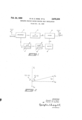
- FIG. 1 is a block diagram of an illustrative system embodying the invention.
- Fig. 2 is a vector diagram of various frequency components at the input converter.
- a received signal of frequency f appears at input converter 10, together with a signal f from local oscillator 12, and the resulting differencefrequency 1, is applied to intermediate-frequency ampliher 14.
- the intermediate-frequency signal is heterodyned in mixer 16 with a signal from oscillator 12 to provide transmitted sidebands (foifi) one of which equals 1, in frequency, the other being a transmitted image frequency.
- a carrier signal f will be passed if unit 16 is not designed as a balanced mixer.
- the local oscillator signal for mixer 16 is derived through a buffer 13 to prevent the signals in the mixer from affecting local oscillator 12, and through phase control the purpose and adjustment of which will hereafter be explained.
- Intermediate-frequency amplifier 14 preferably has a broad frequency range extending substantially to zero, and converter 10 and mixer 16 and possibly buffer 18 are of broad-band design, with local oscillator 12 adjustable in frequency. While the present invention is primarily valuable in broad-band application, it is not limited thereto. It is, however, a practical requirement that the repeater should, over all, emit and respond to the transmitted image of a signal equally with its response to the relayed signal itself, as will be seen.
- 2% initted sidebands may be unequal, provided that there is compensation at the input end of the repeater.
- phase control 20 The purpose of phase control 20 is to prevent the repeater from oscillating. To test the tendency of the system to oscillate, apart from accomplishing its function "as a repeater, it may be assumed that a signal j, appears in intermediate frequency amplifier 14. This signal is applied with oscillator signal f to mixer 16 to produce sideband frequencies (f -t-f and (f -i Only if mixer 16 is perfectly balanced, will there be no signal of frequency of 1",, in the output. Signals (f d-f and (fir-f1) from the mixerare transmitted and appear at the repeater input. They are represented in Fig. 2 as vectors contrarotating at frequency, which in the normal case remain symmetrical relative to the transmitted oscillator voltage representedby stationary vector f,,,,. The line of symmetry f of the two sidebands replaces vector f,,,, as
- the two difference-frequency signals, resulting at the input converter from mixing the oscillator signal with the above-described pair of equalamplitude sidebands are mutually canceling provided that the resultant oscillator signal used in the conversion is in quadrature with the line of symmetry bf the sidebands.
- This resultant oscillator signal is representedin Fig. 2 by the vector j
- the actual oscillator signal f must be phased substantially to cancel the componentof oscillator frequency i among the received signals, should any such component be present.
- the resultant oscillatorfrequency signal j is the vector sum of the actual oscillator signal f and the replica f of f
- the transmitted oscillator-frequency component need not coincide with the line of symmetry f as shown.
- the cancellation is true for as many symmetrical pairs of sidebands as are considered, with the same phase of resultant oscillator signal: at right angles to the common line of symmetry.
- the transmitted signals originate as symmetrical sidebands, and some symmetry-not necessarily an unchanged symmetry-must be preserved in the feedback loop despite the unavoidable phase shifts.
- the transmitting antenna, the receiving antenna, the space between the two, and certain components of the input converter and the output mixer are all factors which cause phase shift of the transmitted signals as detected by the repeater.
- the phase shifts that occur between the antennas and within ideal transmission lines that may be parts of the repeater are accurately proportional to the transmitted frequencies. Whether this proportionality is maintained in design of the other phase-shifting components or not, the feedback loop should be of such over-all design as to maintain symmetry between the transmitted pairs of sidebands, relative to a common reference line if more than a single pair is to be transmitted as in broad-band application.
- the received signal may then be amplified far beyondv the limited gain permissible with isolated and phased transmitting and receiving antennas of prior art systems, Multiple received signals may effectively be repeated concurrently since the same relative phase of oscillator signals as the input and output converters is operative to suppress singing for all values of h.
- the high gain permissible for multiple signals is limited by the extent of inequality of the transmitted sidebands and their asymmetry at the input converter in relation to a common reference line.
- the higher frequency components of the signal after conversion for the intermediate-frequency amplifien' such as the oscillator signal itself and the sum-frequencies of the oscillator and the sidebands, may be eliminated by filtering.
- a radio repeater system of a receiving antenna feeding a converter, a local oscillator adapted to cooperate with said converter to produce an intermediate frequency signal when combined with a signal from said antenna, an amplifier for said intermediate signal, a mixer coupled to said amplifier, buffer and phase control units coupled to said local oscillator and adapted to feed a portion of the output'of said local oscillator in proper phase relationship to said mixer, whereby to produce a signal to be transmitted comprising a selected signal and the image thereof, and a transmitting antenna asrasae associated with said mixer and adapted to transmit said selected signal.
- a non-self-oscillating signal repeater comprising the combination of a phase shifter with a signal repeater of the type having equal phase shift and amplification characteristics for both the signal to be relayed and its image signal, said repeater including means for receiving said relayed signal, an input converter connected to said receiving means, an intermediate frequency amplifier connected to said input converter, an output converter connected to said intermediate frequency amplifier, means connected to said output converter for transmitting the amplified signal to be relayed, a portion of the transmitted signal being fed back to said receiving means, and a local oscillator connected to said input converter and to said output converter, the output signal from said output converter comprising upper and lower sidebands consisting of the sum and difference frequencies of the local oscillator signal and the intermediate frequency signal, and said phase shifter being connected between said local oscillator and one of said converters to shift the phase of the local oscillator signal which passes to said converter, the resultant of said phase-shifted local oscillator signal and any local oscillator signal component which has been fed back into the receiving means being,
- phase shifter is connected between said local oscillator and said output converter.
Landscapes
- Engineering & Computer Science (AREA)
- Computer Networks & Wireless Communication (AREA)
- Signal Processing (AREA)
- Radio Relay Systems (AREA)
Description
Feb. 24, 1959 D. G. HARE ETAL 2,875,328
REPEATER STATION HAVING REDUCED SELF OSC ILLATION Filed Oct. 12, 1945 1+ CONVERTER f1 ,WXER f5. 1'} AMPLIFIER I 0P o fHASE M EUFFEI? f osclimrox col/mm INVENTORS Dona/o G. C. Hare BY Hecfor k s/w'fzer QWLLW Donald G. C. Hare, Greenvale, and Hector United States Patent REPEATER STATION HAVING REDUCED SELF OSCILLATION R. Shifter,
Manhasset, N. Y, assignors to the United States of America as represented by the Secretary of the Navy Application October- 12 1945, Serial No. 622,054 3 Claims. ('Cl. 259-15) This invention relates to radio repeaters. The object is to provide an improved repeater system in which the tendency to oscillate due to feedback from the transmitting antenna to the receiving antenna is minimized.
In accomplishing the invention, the received signal is heterodyned to an intermediate frequency using a local oscillator inthe conventional manner. The intermediate frequency signal when amplified is converted for transmission using a signal from the same local oscillator. Both the repeated signal and its image are transmitted,
and when the local oscillator frequency is greater than that of the intermediate frequency, the image signal has -a frequency greater thanthe received signal by an amount equal to "twice the intermediate frequency signal. The repeated and image signals inherently are fed back to the receiving antenna, and should be equal in amplitude at the input converter. According to this invention, the oscillator signal at the output mixer is critically phased relative to the oscillator signal for the input converter. The phasing is such that the two difference-frequency signals, which result at the input converter from themixlng of the oscillator signal with the two transmitted sidebands, are mutually canceling. The tendency of the repeater to oscillate is thus largely eliminated. This system is especially useful for repeaters of broad-band design, where antenna phasing is difiioult orimpossible.
The invention will be better understood from the following detailed disclosure in which:
Fig. 1 is a block diagram of an illustrative system embodying the invention; and
Fig. 2 is a vector diagram of various frequency components at the input converter.
As shown in Fig. 1, a received signal of frequency f appears at input converter 10, together with a signal f from local oscillator 12, and the resulting differencefrequency 1, is applied to intermediate-frequency ampliher 14. The intermediate-frequency signal is heterodyned in mixer 16 with a signal from oscillator 12 to provide transmitted sidebands (foifi) one of which equals 1, in frequency, the other being a transmitted image frequency. In addition, a carrier signal f will be passed if unit 16 is not designed as a balanced mixer.
The local oscillator signal for mixer 16 is derived through a buffer 13 to prevent the signals in the mixer from affecting local oscillator 12, and through phase control the purpose and adjustment of which will hereafter be explained.
Intermediate-frequency amplifier 14 preferably has a broad frequency range extending substantially to zero, and converter 10 and mixer 16 and possibly buffer 18 are of broad-band design, with local oscillator 12 adjustable in frequency. While the present invention is primarily valuable in broad-band application, it is not limited thereto. It is, however, a practical requirement that the repeater should, over all, emit and respond to the transmitted image of a signal equally with its response to the relayed signal itself, as will be seen. The transasrsszs Patented Feb. 24, 19:59
2% initted sidebands may be unequal, provided that there is compensation at the input end of the repeater.
The purpose of phase control 20 is to prevent the repeater from oscillating. To test the tendency of the system to oscillate, apart from accomplishing its function "as a repeater, it may be assumed that a signal j, appears in intermediate frequency amplifier 14. This signal is applied with oscillator signal f to mixer 16 to produce sideband frequencies (f -t-f and (f -i Only if mixer 16 is perfectly balanced, will there be no signal of frequency of 1",, in the output. Signals (f d-f and (fir-f1) from the mixerare transmitted and appear at the repeater input. They are represented in Fig. 2 as vectors contrarotating at frequency, which in the normal case remain symmetrical relative to the transmitted oscillator voltage representedby stationary vector f,,,,. The line of symmetry f of the two sidebands replaces vector f,,,, as
a preference line when f is reduced to zero, or when f g is at an angle to line of symmetry f,,. To obtain the transmitted signal trace, it is merely necessary to find the sine-variation of the instantaneous vectors shown when the diagram is caused to rotate at the oscillatory frequency. h
it can be shown that the two difference-frequency signals, resulting at the input converter from mixing the oscillator signal with the above-described pair of equalamplitude sidebands, are mutually canceling provided that the resultant oscillator signal used in the conversion is in quadrature with the line of symmetry bf the sidebands. This resultant oscillator signal is representedin Fig. 2 by the vector j The actual oscillator signal f must be phased substantially to cancel the componentof oscillator frequency i among the received signals, should any such component be present. The resultant oscillatorfrequency signal j is the vector sum of the actual oscillator signal f and the replica f of f In the general case, the transmitted oscillator-frequency component need not coincide with the line of symmetry f as shown. The cancellation is true for as many symmetrical pairs of sidebands as are considered, with the same phase of resultant oscillator signal: at right angles to the common line of symmetry.
The transmitted signals originate as symmetrical sidebands, and some symmetry-not necessarily an unchanged symmetry-must be preserved in the feedback loop despite the unavoidable phase shifts. The transmitting antenna, the receiving antenna, the space between the two, and certain components of the input converter and the output mixer are all factors which cause phase shift of the transmitted signals as detected by the repeater. The phase shifts that occur between the antennas and within ideal transmission lines that may be parts of the repeater are accurately proportional to the transmitted frequencies. Whether this proportionality is maintained in design of the other phase-shifting components or not, the feedback loop should be of such over-all design as to maintain symmetry between the transmitted pairs of sidebands, relative to a common reference line if more than a single pair is to be transmitted as in broad-band application. There will be a critical phase relationship of the oscillator output signals supplied to the input converter and to the output mixer for mutual cancellation of one and all pairs of the converted sidebands (f -H and f f,-). The phase of the signal of oscillator frequency (other factors unchanged), as applied to mixer 16, determines the phase of line f at the input converter relative to the oscillator signal applied to that converter. This phase may be adjusted by shifter 20 in the channel beor at any ccived signal. The equal, symmetrical image frequency which is characteristic of the transmission does not accompany the usual received signal. The received signal may then be amplified far beyondv the limited gain permissible with isolated and phased transmitting and receiving antennas of prior art systems, Multiple received signals may effectively be repeated concurrently since the same relative phase of oscillator signals as the input and output converters is operative to suppress singing for all values of h. The high gain permissible for multiple signals is limited by the extent of inequality of the transmitted sidebands and their asymmetry at the input converter in relation to a common reference line.
The higher frequency components of the signal after conversion for the intermediate-frequency amplifien'such as the oscillator signal itself and the sum-frequencies of the oscillator and the sidebands, may be eliminated by filtering. There will remain in the output of converter 10 a signal of twice f the cross-product of the signal and image frequencies. This double-frequency component does not tend to establish oscillation. Furthermore, it may be made quite small in relation to the desired modulation products by making the oscillator signal strong relative to the received signal components, as in conventional superheterodyne practice.
It is to be understood that variousmodifications and changes may be made in this invention without departing from the spirit and scope thereof.
What is claimed is:
l. The combination, in a radio repeater system, of a receiving antenna feeding a converter, a local oscillator adapted to cooperate with said converter to produce an intermediate frequency signal when combined with a signal from said antenna, an amplifier for said intermediate signal, a mixer coupled to said amplifier, buffer and phase control units coupled to said local oscillator and adapted to feed a portion of the output'of said local oscillator in proper phase relationship to said mixer, whereby to produce a signal to be transmitted comprising a selected signal and the image thereof, and a transmitting antenna asrasae associated with said mixer and adapted to transmit said selected signal.
2. A non-self-oscillating signal repeater comprising the combination of a phase shifter with a signal repeater of the type having equal phase shift and amplification characteristics for both the signal to be relayed and its image signal, said repeater including means for receiving said relayed signal, an input converter connected to said receiving means, an intermediate frequency amplifier connected to said input converter, an output converter connected to said intermediate frequency amplifier, means connected to said output converter for transmitting the amplified signal to be relayed, a portion of the transmitted signal being fed back to said receiving means, and a local oscillator connected to said input converter and to said output converter, the output signal from said output converter comprising upper and lower sidebands consisting of the sum and difference frequencies of the local oscillator signal and the intermediate frequency signal, and said phase shifter being connected between said local oscillator and one of said converters to shift the phase of the local oscillator signal which passes to said converter, the resultant of said phase-shifted local oscillator signal and any local oscillator signal component which has been fed back into the receiving means being, vectorially, in quadrature phase relationship with the line of symmetry between said upper and lower sidebands.
3. A device of the type set forth in claim 2, wherein said phase shifter is connected between said local oscillator and said output converter.
References Cited in the file of this patent V UNITED STATES PATENTS
Priority Applications (1)
| Application Number | Priority Date | Filing Date | Title |
|---|---|---|---|
| US622054A US2875328A (en) | 1945-10-12 | 1945-10-12 | Repeater station having reduced self oscillation |
Applications Claiming Priority (1)
| Application Number | Priority Date | Filing Date | Title |
|---|---|---|---|
| US622054A US2875328A (en) | 1945-10-12 | 1945-10-12 | Repeater station having reduced self oscillation |
Publications (1)
| Publication Number | Publication Date |
|---|---|
| US2875328A true US2875328A (en) | 1959-02-24 |
Family
ID=24492755
Family Applications (1)
| Application Number | Title | Priority Date | Filing Date |
|---|---|---|---|
| US622054A Expired - Lifetime US2875328A (en) | 1945-10-12 | 1945-10-12 | Repeater station having reduced self oscillation |
Country Status (1)
| Country | Link |
|---|---|
| US (1) | US2875328A (en) |
Cited By (2)
| Publication number | Priority date | Publication date | Assignee | Title |
|---|---|---|---|---|
| US3429999A (en) * | 1966-09-06 | 1969-02-25 | Collins Radio Co | Circuit for preventing singing in audio systems |
| WO1982000553A1 (en) * | 1980-08-11 | 1982-02-18 | Inc Motorola | Tag generator for a same-frequency repeater |
Citations (6)
| Publication number | Priority date | Publication date | Assignee | Title |
|---|---|---|---|---|
| US1658851A (en) * | 1921-12-28 | 1928-02-14 | American Telephone & Telegraph | Directive radio repeating system |
| US1668270A (en) * | 1922-11-20 | 1928-05-01 | Western Electric Co | Radiosignaling |
| US2279177A (en) * | 1939-12-04 | 1942-04-07 | Plebanski Jozef | Superheterodyne receiving system |
| US2344813A (en) * | 1941-09-26 | 1944-03-21 | Rca Corp | Radio repeater |
| US2347398A (en) * | 1942-05-01 | 1944-04-25 | Rca Corp | Modulation system |
| US2369268A (en) * | 1942-05-27 | 1945-02-13 | Rca Corp | Radio repeater |
-
1945
- 1945-10-12 US US622054A patent/US2875328A/en not_active Expired - Lifetime
Patent Citations (6)
| Publication number | Priority date | Publication date | Assignee | Title |
|---|---|---|---|---|
| US1658851A (en) * | 1921-12-28 | 1928-02-14 | American Telephone & Telegraph | Directive radio repeating system |
| US1668270A (en) * | 1922-11-20 | 1928-05-01 | Western Electric Co | Radiosignaling |
| US2279177A (en) * | 1939-12-04 | 1942-04-07 | Plebanski Jozef | Superheterodyne receiving system |
| US2344813A (en) * | 1941-09-26 | 1944-03-21 | Rca Corp | Radio repeater |
| US2347398A (en) * | 1942-05-01 | 1944-04-25 | Rca Corp | Modulation system |
| US2369268A (en) * | 1942-05-27 | 1945-02-13 | Rca Corp | Radio repeater |
Cited By (3)
| Publication number | Priority date | Publication date | Assignee | Title |
|---|---|---|---|---|
| US3429999A (en) * | 1966-09-06 | 1969-02-25 | Collins Radio Co | Circuit for preventing singing in audio systems |
| WO1982000553A1 (en) * | 1980-08-11 | 1982-02-18 | Inc Motorola | Tag generator for a same-frequency repeater |
| US4317217A (en) * | 1980-08-11 | 1982-02-23 | Motorola, Inc. | Tag generator for a same-frequency repeater |
Similar Documents
| Publication | Publication Date | Title |
|---|---|---|
| US2369268A (en) | Radio repeater | |
| US2951152A (en) | Radio diversity receiving system | |
| US3021521A (en) | Feed-through nulling systems | |
| US2462841A (en) | Frequency-stabilizing system | |
| US4544926A (en) | Adaptive jamming-signal canceler for radar receiver | |
| US2530614A (en) | Transmitter and receiver for single-sideband signals | |
| US2344813A (en) | Radio repeater | |
| US2714634A (en) | Modulated radio frequency signal amplifier | |
| GB1387579A (en) | Doppler radar systems | |
| US2424796A (en) | Superheterodyne radio altimeter or locator | |
| US2875328A (en) | Repeater station having reduced self oscillation | |
| GB689082A (en) | Improvements in or relating to radio transmission systems | |
| US3670327A (en) | Continuous wave radar systems | |
| US4183022A (en) | Transponder for radiocommunication system, particularly for measuring the distance between two stations | |
| US2587590A (en) | Ultrahigh-frequency apparatus | |
| US2193801A (en) | Signal receiving system | |
| US3217259A (en) | Receiver utilizing phase-locked parametric amplifier | |
| US2789210A (en) | Mixing circuit for microwave frequencies | |
| US2591264A (en) | Television receiver | |
| US2961533A (en) | Synchronizing frequency control system | |
| US2557194A (en) | Amplifier system for alternating voltages | |
| GB590209A (en) | Improvements in or relating to radio receivers operating with diversity reception | |
| GB655773A (en) | Means for receiving electric wave communication signals | |
| US3069630A (en) | Diversity receiving system | |
| US3624513A (en) | Image frequency suppression circuit |