US2850252A - Inflatable mat structure - Google Patents
Inflatable mat structure Download PDFInfo
- Publication number
- US2850252A US2850252A US302975A US30297552A US2850252A US 2850252 A US2850252 A US 2850252A US 302975 A US302975 A US 302975A US 30297552 A US30297552 A US 30297552A US 2850252 A US2850252 A US 2850252A
- Authority
- US
- United States
- Prior art keywords
- cell
- cells
- fabric
- envelope
- walls
- Prior art date
- Legal status (The legal status is an assumption and is not a legal conclusion. Google has not performed a legal analysis and makes no representation as to the accuracy of the status listed.)
- Expired - Lifetime
Links
- 239000004744 fabric Substances 0.000 description 75
- 230000008093 supporting effect Effects 0.000 description 42
- 239000012530 fluid Substances 0.000 description 26
- 238000010276 construction Methods 0.000 description 5
- 238000004873 anchoring Methods 0.000 description 4
- 230000000694 effects Effects 0.000 description 3
- 230000004048 modification Effects 0.000 description 3
- 238000012986 modification Methods 0.000 description 3
- 230000002787 reinforcement Effects 0.000 description 3
- 229910000831 Steel Inorganic materials 0.000 description 2
- 239000011248 coating agent Substances 0.000 description 2
- 238000000576 coating method Methods 0.000 description 2
- 239000002184 metal Substances 0.000 description 2
- 239000010959 steel Substances 0.000 description 2
- 239000004677 Nylon Substances 0.000 description 1
- 239000007767 bonding agent Substances 0.000 description 1
- 238000007373 indentation Methods 0.000 description 1
- 238000007689 inspection Methods 0.000 description 1
- 229920001778 nylon Polymers 0.000 description 1
- 230000000717 retained effect Effects 0.000 description 1
- 239000004576 sand Substances 0.000 description 1
- 238000006467 substitution reaction Methods 0.000 description 1
- 239000004753 textile Substances 0.000 description 1
- 238000009732 tufting Methods 0.000 description 1
- XLYOFNOQVPJJNP-UHFFFAOYSA-N water Substances O XLYOFNOQVPJJNP-UHFFFAOYSA-N 0.000 description 1
Images


Classifications
-
- B—PERFORMING OPERATIONS; TRANSPORTING
- B64—AIRCRAFT; AVIATION; COSMONAUTICS
- B64F—GROUND OR AIRCRAFT-CARRIER-DECK INSTALLATIONS SPECIALLY ADAPTED FOR USE IN CONNECTION WITH AIRCRAFT; DESIGNING, MANUFACTURING, ASSEMBLING, CLEANING, MAINTAINING OR REPAIRING AIRCRAFT, NOT OTHERWISE PROVIDED FOR; HANDLING, TRANSPORTING, TESTING OR INSPECTING AIRCRAFT COMPONENTS, NOT OTHERWISE PROVIDED FOR
- B64F1/00—Ground or aircraft-carrier-deck installations
- B64F1/36—Other airport installations
Definitions
- FIG. 3 INFLATABLE MAT STRUCTURE Filed Aug. 6, 1952 s Sheet-Sheet 2
- the present invention relates broadly to a novel form of fluid inflatable mat structure or assembly. More particularly, the invention is concerned with a form of cushion or mat embodying a plurality of individually inflatable compartments or cells of fluid-tight construction which are adapted to be arranged in juxtaposed relation and which cooperate to provide, when properly anchored in place, a landing mat for a projectile, aircraft or the like.
- a further object of the present invention is to provide an inflatable mat structure having the foregoing attributes and advantages as well as being capable of being disassembled and readily reassembled in a different location.
- Another object of the invention is to provide an inflatable mat stmcture the height, configuration and volumetric efliciency of which may be readily varied by simple mechanical expedients.
- Fig. l of the drawings represents a partial perspective view with parts broken away illustrating one form of an assembly or mat structure embodying the principles of the present invention.
- Fig. 2 is a partial greatly enlarged vertical section taken lengthwise through the mat structure shown in Fig. 1.
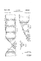
- Fig. 3 is a vertical section generally similar to Fig. 2 but showing a part of one end of the mat structure illustrated in Fig. 1.
- Fig. 4, Fig. 5 and Fig. 6 disclose certain particular features of the assembly at an enlarged scale.
- Fig. 7 and Fig. 8 illustrate diagrammatically a modified arrangement of the tie members.
- Fig. 9 is a partial perspective view corresponding to Fig.
- Fig. 10 and Fig. 11 are enlarged vertical sections taken along the line 1010 in Fig. 9 and line 11 11 in Fig. 10 respectively.
- the reference numeral 1 identifies the inflatable or cushioned mat structure generally which, as has been indicated, embodies a number of individual elements in combination.
- the mat structure 1 comprises a plurality of individual compartments or cells 2.
- Each of the several cells 2 is fabricated from a series of fabric strips 3 of predetermined width and length which have a fluid-impervious coating thereon and co operate when assembled in a manner described hereinafter to define a fluid-tight chamber 4.
- Disposed internally of the chamber 4 are a plurality of tie members 5 and 6.
- the tie members 5 are preferably located inwardly from the marginal extremities of the individual cells 2 while the tie members 6, being of somewhat shorter length, are located in close proximity to the marginal extremities thereof.
- Each tie member 5 and 6 embodies a flexible element such as a suitable textile strand, rope or the steel cable 7. It is especially advantageous that the tie members 5 and 6 possess some resiliency and, therefore, to design for certain types of loading character istics in the cells 2, it may be found to be desirable to employ a nylon cord rather than the relatively nonelastic steel cable 7.
- the opposite ends of the cable 7 are adapted to be passed around thimbles 8 to form a loop and secured in place by means of a plurality of metal press clips or fasteners 9.
- a snap hook 10 which is adapted to detachably engage a D-ring 11.
- Each of the D-rings 11 is secured to the innermost surface of the fabric strips 3 forming the cell 2 and within the chamber 4 by means of one or more patches 12 which are securely attached to the fabric wall by means of a suitable bonding agent.
- the resulting construction has the general appearance of tufting or quilting but is intended to insure that the fabric strips 3 cooperating to form the walls which define the chamber 4 of the cell 2 will be retained in substantially parallel relation to each other when the chamber is fully inflated with fluid under pressure.
- tie members 5 and 6 need not be vertically disposed nor in parallel relation to each other (see Figs. 7 and 8). The same result may be obtained by securing the tie members 5 and 6 in angular or diagonal relation to the fabric walls comprising the fabric strips 3 cooperating to form each cell 2 as indicated by the tie members 61 (Fig. 7). Where a diagonal arrangement is employed, the tie members 5 and 6 may be of extended length such as tie members 62 (Fig. 8) and merely pass through or otherwise suitably engage the D-rings 11.
- the inflation of the chamber 4 of each cell 2 is accomplished by attaching a suitable fluid supply means (not shown), preferably supplying air, to the inlet tube 14.
- a suitable fluid supply means (not shown), preferably supplying air, to the inlet tube 14.
- the inlet tube 14, when not in use, is adapted to be anchors 21 in the associated attaching devices '22 '1' and 2 of the drawings.
- the closure 15 is advantageously main-' tained in closed relation by a series of slide fasteners 16 which render the inlet tube 14 readilyaccessiblefrorn the exterior of the cell 2.
- a number of inflating valves or ports 1'7v are provided to facilitate jthe bolstering of the pressure of the fluid within the chamber 4.
- a number ofthese ports- 17 may be arranged in substantially equally spjac ed rela -t tion along the opposite margins of the cell 2
- a threaded hook 23 is attached to the portion of the Wire reenforcement 19 exposed in each of the notches 210 formed in the fabric envelope 1% (see Fig.4).
- a similar threaded thook 24 cooperates with the threaded hook 23, both of which are threaded into the turnbuckle 25,.to draw the fabric envelope 18 toward the attaching eye 26 of" a groundscrew 27 or the like which serves to anchor'the: entire assembly to the surface upon which the inflatablemat structure 1;is disposed.
- the tautness of the fabric envelope 18 may be readily adjusted by the manipulation of the turnbuckle 25,
- The'ground screw 27 is inserted into the earth, where this isthe surface supporting, the inflatable mat structure 1,-;to a depth such that the flange. 28 adjacent the eye 26 thereon engagesthe surfaceof the ground.
- V e In order to provide a sloping approachto and descent 1 from the exposed surface of the'inflatablernat structure l and its fabn'c envelope 1% in, the formof a ramp,
- the logs 33 and 34 as well as the logs 32 are provided with inflating valves or ports 43 identical to the ports 17 on each of the cells 2.
- Eachcell 2 is made up of a series of cooperating fabric strips 3 of predetermined length and width and coated with a suitable fluid-impervious coating such, for example, as natural or artifit will be understood that the several fab-v are joined together by overlapping as at 44 (Fig. 2) and reenforced by the addition of the tape 45 over each lap joint to form the fluid-tight chamber4.
- a suitable fluid-impervious coating such, for example, as natural or artifit will be understood that the several fab-v are joined together by overlapping as at 44 (Fig. 2) and reenforced by the addition of the tape 45 over each lap joint to form the fluid-tight chamber4.
- each cell 2 In order to. facilitate theoperation of each cell 2, it is desirable to provide an. access opening to permit entrance to the chamber 4 by personnel to change or adjust the tie members 5 and 6. It Willbe understood that the substitution of tie members 5 and 6 of longer or shorter length, as the case may be, will serve to modify 7 the overall height and volumetric efiiciency of the individual chamber 4 of eachcell 2. In general, the overall height of each cell 2 should be capable of variance from approximately 2 to 5 feet depending upon the weight of the object which is to be supported thereon andthe cushioning or resilient effect required to prevent damage to the object as it strikes the surface of the fab.-
- the access opening 46 (see Fig. l) is advantageously provided with a tubular member 47 madetof flexible fabric and generally similar to the inlet tube 14 through which a person can enter the'charnber 40f the cell 2. .
- the tubular member 47 is, adapted to be folded shut and inserted in the chamber 4 to prevent the escape of the inflating fluid therefrom when the access openingiis not inuse.
- a slide fastener 48 is provided to close the access opening 46 and retain the tubular member 47 within...
- the envelope is arranged to be'extended' over a plurality' of 'g enerally cylindrical inflatable members 'or logs 32,33
- logs 32, 33, 34 are of substantially identical construction in that they employ, 1 as indicated in Fig.3, a'fabric strip 35 the edges of which arel'apped as at 36 and covered byafr'eenforcing tape 37.
- Each. log 32, 33, '34 is provided with a dome-shaped end por I tionj38 formed of anurnber of fabric pieces joi d fgether (see Fig. l)
- Each of the logs 32 is provided with an inlet tube 39 generally similar totheinlet tube 14 of each cell 2 to facilitate the introduction of fluid to the fluid-tight chamber 40 thereof.- A closure 41 and slide fasteners 42' enforced bythe crotch tape 56. The ramp 54 is stretched Moreover, the logs 32, .33, 34 may be removed entirely ;by providing analternate structure such as that illus trated in Fig. 6 of the drawings; This modification embodies a fabric envelope 49 of one ormore'plies similar to the fabric envelope. 18.
- the fabric envelope 49 isadapted to be drawn down over the end cell 2 and secured 'in position as by means of" the-ground anchor 50 andv the'attaching devices 51 (identical to the corresponding parts 20 and 21) of which the latter engage those portions of the wire reenforcement 52 exposed by the notches 53 in the edge of the envelope.
- a flexible fabric strip forming a ramp 54 the edge of the strip being cemented at Site the envelope and retautby means of the attaching devices57 and the ground anchors 58 (identical to the-corresponding parts 20 and21).- As before, the attaching devices engage those portions of the wire reenforcement 59 exposed by the notches 60 in the lateral edge of the ramp 54.
- the cell 2 resides in the attaching means for the tie members employed in maintaining the parallelism of the top and bottom walls of the cells when inflated with fluid under pressure.
- the attaching means 65 comprises an endless braided wire rope or cable 66 which is formed into spaced loops 67 about the metal thimbles 68 and anchored in place by press clips or fasteners 69.
- each attaching means 65 is secured in place on the fabric element or curtain 70 by means of the folds 71 which completely encloses the cable.
- a reenforcement or patch 72 is applied to fold 71 on the curtain 76 adjacent the loop 67 to secure the entire assembly in place.
- a portion 73 of the curtain 70 is flanged or folded back and secured to the innermost surface of the fabric strips 3 forming the outer walls of the fluid inflatable chamber 74.
- a crotch tape 75 is employed to reenforce the attachment of the curtain 70 to the fabric strips 3.
- a series of tie members 76 of comparatively shorter lengths than the tie members 5 and 6 of the cells 2 are detachably secured to the loops 67 in the cable 66 for maintaining the walls of the cell 64 in spaced parallel relation when the chamber 74 is filled with fluid under pressure.
- Each tie member 76 is identical in its construction to the tie members 5 and 6.
- An inflatable mat structure comprising a plurality of fluid-tight cells disposed in substantially juxtaposed relation to each other, each of said cells being formed of coated fabric walls sealed at their marginal extremities, a multiplicity of spaced flexible tie members of predetermined length disposed internally of the cell extending between and attached to the top and bottom walls thereof for maintaining said walls in spaced generally parallel relation to each other when the cell is inflated, and means positioned in one wall of each cell for introducing fluid under pressure to each cell; a fabric envelope substantially completely covering the several juxtaposed cells; and a plurality of anchors adjacent the extremities of the envelope so constructed and arranged to secure the envelope and the several cells together in assembled relation.
- An inflatable mat structure comprising a plurality of fluid-tight cells disposed in substantially juxtaposed relation to each other, each of said cells being formed of coated fabric walls sealed at their marginal extremities, a multiplicity of spaced flexible tie members of predetermined length disposed internally of the cell extending between and attached to at least two of the opposed walls thereof for maintaining said walls in spaced generally parallel relation to each other when the cell is inflated, means secured to said walls for demountably attaching the tie members, and inflating means in the wall of each cell; a fabric envelope substantially in contact with and completely covering the several juxtaposed cells; and a plurality of anchors adjacent the cells to secure the en-' velope and the several cells together in assembled relation.
- An inflatable mat structure comprising a plurality of fluid-tight cells disposed in substantially juxtaposed relation to each other, each of said cells being formed of coated fabric walls sealed at their marginal extremities, a multiplicity of spaced flexible tie members of predetermined length disposed internally of the cell and attached to at least two of the opposed walls thereof and maintaining said Walls in spaced generally parallel rela-- tion to each other when the cell is inflated, means secured to the walls for demountably attaching the tie members, means in one wall of said cell for introducing fluid under pressure to each cell to inflate said cell, and means in at least one wall of said cell providing access to the interior of the cell; a fabric envelope substantially com-- pletely covering the several juxtaposed cells; and a plural-- ity of anchors for securing the envelope and the several cells together in assembled relation.
- a cushioned mat structure comprising a plurality of inflatable cells disposed in substantially juxtaposed relation to each other and adapted to be assembled on a sup-- porting surface, each of said cells being formed of coated.
- a cushioned mat structure comprising at least one fluid inflatable cell being formed by oppositely disposed coated fabric Walls joined together and sealed at their marginal extremities to define a fluid-tight chamber, a plurality of flexible tie members of predetermined length disposed in and extending between said walls of said chamber in mutually parallel relation and attached to the opposed walls for maintaining them in spaced parallel relation when the cell is inflated; an envelope substantially completely covering the cell; and anchors attached to the edge of the envelope for securing the envelope and the cell in assembled relation.
- a cushioned mat structure adapted to be mounted upon a rigid supporting surface, said mat structure comprising at least one fluid inflatable cell being formed by oppositely disposed coated fabric Walls joined together and sealed at their marginal extremities to define a fluid-tight chamber, and a plurality of flexible tie members of predetermined length extending between said walls of said chamber whereby the walls of the cell are maintained in spaced, generally parallel relation to each other when the cell is inflated, means aflixed to opposed walls of the cell within the chamber providing a demountable attachment for each of the tie members; a fabric envelope substantially completely covering the cell; a plurality of anchors secured to the supporting surface; and attaching devices securing the envelope to the anchors and urging the cell against the supporting surface.
- a cushioned mat structure adapted to be mounted 7 upon a rigid supporting surface, said mat structure com prisingat least one fluid inflatable cell being formed by oppositely disposed coated fabric walls joined together and sealed at their marginal extremities to define a fluid tight chambena plurality of flexible tie members of predetermined length extending between the top and bottom walls of said chamber whereby the walls of the cell are maintained in spaced generally parallel relation to each other when: the cell is inflated, means afiixed to opposed walls of the cell within the chamber providing a demountable attachment for eachof the tie'members; a fabric ,envelope substantially completely covering the cell; a plurality of anchors secured to the supporting'surface; at-
- taching devices securing the envelope to the anchors and urging the cell against the supporting surface; and means disposed adjacent each end of the cell providing an in clined ramp from the supporting surface to the fabric envelope extending over the cell, v
- a cushioned mat structure adapted to be'mounted upon a rigid supporting surface, said mat structure comprising a' plurality of fluid inflatable cells arranged in spaced mutually parallel relation, each of said cells being formed of opposed fabric. walls joined together and a sealed at the marginal extremities thereof to define a fluid-tight chamber, a multiplicity of flexible tie mem bers of predetermined length disposed in and'ext'en'ding between the top and bottom walls of said chamber whereby the walls of the cell are maintained in spaced generally parallel relation to each other when the cell is inflated, means'afl'ixed to said top and bottom walls of the cell within the chamber providing demountable at tachments for each of the tie members; a fabric envelope substantially completely covering the several cells; a plusubstantially completely covering them; and aplurality of anchors on the.
- each of said cells beingformed of a pair of opposed coated fabric walls joined and sealed at their marginal extremities to define a fluid? tight chamber therein, a multiplicity of spaced flexible tie members of predetermined length disposed in the cham-r her and attached :to the-opposite walls of-lthe cell for.
- a fabric envelope corresponding in its dimensions generally to the combined dimensions ofitheseveral'assembled cells and wall ofrthe cell providing access to the chamber of the cell, and inflating means in one wall of the cell for introducing;
- ' members means: in one wallof'the. cell providing access I to the chamber of thecell, and'inflating means'in at least? one wall of the cell forintroducing fluid under pressure to the chamber; afabric envelope corresponding-in its' dimensions to. the combined dimensions of the several assembled cells and substantially completely'covering them; a plurality of anchors on the supporting surface; and attaching devices securing the envelope to the anchors to maintain the severalrcells in assembled relation with respect to the supporting surface.
- said landing structure comprising a plurality of individually inflatable cells arranged in spaced mutually parallelirelation, each-of said cells being formed of a pair of opposed coated :fabric walls joined together. and sealedat their'marginal extremities tov define a fluidtight chamber therein, armultiplicity of spaced flexible tie members of predetermined-length disposed in' the chamber and attachedto the oppositetwalls of the cell for imaintaining them in. predetermined spaced generally parallel relation to each otherawhen the cell .is. inflated,
- a cushioned mattress-type landing structure for aircraft and the like adapted. to be. disposed upon a rigid supporting surface," said landing structure comprising a plurality of-individually' inflatable cells arranged in spaced mutually parallel relation, each of. said cells being formed of a pair of opposed coated fabric walls joined together and sealed at their marginal extremities to define a fluidi tight-chamberthereinfa multiplicity of spaced flexible tie members of predetermined length disposed in the chamber'and attached to .the opposite walls of the cell 'forimaintaining themtinjpredetermined spaced generally parallel relation to each; other when the cell is inflated,
- drical shape disposed adjacent the end cells and supporting the projecting portion of the fabric envelope in inclined relation to the remaining portion thereof disposed on the cells; and a plurality of anchors secured to the supporting surface and arranged adjacent the extremities of the end cells and in the spaces therebetween for securing the several cells and the envelope in place on the supporting surface.
- a fabric envelope completely covering and extending be yond the longitudinal extremities of the assembled cells; a plurality of anchors attached to the supporting surface and disposed adjacent the extremities of the assembled cells and in the spaces therebetween; adjustable attaching devices securing the envelope to the anchors to stretch the envelope and urge the cells against the supporting surface; and a plurality of generally cylindrically shaped inflatable members of graduated diameters arranged to support the portion of the fabric envelope extending beyond the extremities of the assembled cells in the form of an incline from the supporting surface to the fabric envelope covering the several cells.
Landscapes
- Engineering & Computer Science (AREA)
- Mechanical Engineering (AREA)
- Aviation & Aerospace Engineering (AREA)
- Mattresses And Other Support Structures For Chairs And Beds (AREA)
Description
p 1 5 c. J. FORD 2,850,252
INFLATABLE MAT STRUCTURE Filed Aug. .6, 1952 3 Sheets-Sheet 1 ATTbRNEY Sept. 2, 1958 c. J. FORD 2,850,252
4 INFLATABLE MAT STRUCTURE Filed Aug. 6, 1952 s Sheet-Sheet 2 FIG. 3
INVENTOR. CHARLES J. FORD ATTORNEY Sept. 2, 1958 c. J. FORD INFLATABLE MAT STRUCTURE 3 Sheets-Sheet 3 Fileq Aug. 6, 1952 0- di a. t
INVENTOR. CHARLES J. FORD ATT United States Patent INFLATABLE MAT STRUCTURE *Charles 1. Ford, Akron, Ohio, assignor, by mesne assignments, to The Goodyear Tire & Rubber Company, a corporation of Ohio Application August 6, 1952, Serial No. 302,975
16 Claims. (Cl. 244-114) The present invention relates broadly to a novel form of fluid inflatable mat structure or assembly. More particularly, the invention is concerned with a form of cushion or mat embodying a plurality of individually inflatable compartments or cells of fluid-tight construction which are adapted to be arranged in juxtaposed relation and which cooperate to provide, when properly anchored in place, a landing mat for a projectile, aircraft or the like.
It is one of the purposes of the invention to provide a cushioned or resilient surface embodying an assembly of fluid inflatable elements which can be suitably anchored in place on the ground, on the deck of a vessel, on a body of water or other similar location to break the fall of an air-borne object such, for example, as a landing aircraft.
It is a further object of the present invention to provide a mat structure which affords a landing surface of the inflatable mattress type which is made up of several component parts all of which may be readily deflated and transported from one place to another.
A further object of the present invention is to provide an inflatable mat structure having the foregoing attributes and advantages as well as being capable of being disassembled and readily reassembled in a different location.
Another object of the invention is to provide an inflatable mat stmcture the height, configuration and volumetric efliciency of which may be readily varied by simple mechanical expedients.
Ordinary bed mattresses of the fluid inflatable type embodying internally disposed spaced tie members are well known. However, the particular combination of several mattress-like compartments or cells of considerably greater size and of the specific construction contemplated by the present invention as well as the cooperation therewith of certain other important elements is believed to produce a novel result. Moreover, the inflatable mat structure of the present invention possesses all of the desired advantages and successfully accomplishes the several objects sought to be achieved in its conception.
Other objects and advantages of the present invention beyond those mentioned above will be apparent from the following description of one form of the invention as illustrated in the accompanying drawings.
Fig. l of the drawings represents a partial perspective view with parts broken away illustrating one form of an assembly or mat structure embodying the principles of the present invention. Fig. 2 is a partial greatly enlarged vertical section taken lengthwise through the mat structure shown in Fig. 1. Fig. 3 is a vertical section generally similar to Fig. 2 but showing a part of one end of the mat structure illustrated in Fig. 1. Fig. 4, Fig. 5 and Fig. 6 disclose certain particular features of the assembly at an enlarged scale. Fig. 7 and Fig. 8 illustrate diagrammatically a modified arrangement of the tie members. Fig. 9 is a partial perspective view corresponding to Fig.
1 of another embodiment of the invention. Fig. 10 and Fig. 11 are enlarged vertical sections taken along the line 1010 in Fig. 9 and line 11 11 in Fig. 10 respectively.
In Fig. 1 the reference numeral 1 identifies the inflatable or cushioned mat structure generally which, as has been indicated, embodies a number of individual elements in combination. The mat structure 1, as illustrated, comprises a plurality of individual compartments or cells 2. Each of the several cells 2 is fabricated from a series of fabric strips 3 of predetermined width and length which have a fluid-impervious coating thereon and co operate when assembled in a manner described hereinafter to define a fluid-tight chamber 4. Disposed internally of the chamber 4 are a plurality of tie members 5 and 6.
The tie members 5 are preferably located inwardly from the marginal extremities of the individual cells 2 while the tie members 6, being of somewhat shorter length, are located in close proximity to the marginal extremities thereof. Each tie member 5 and 6 embodies a flexible element such as a suitable textile strand, rope or the steel cable 7. It is especially advantageous that the tie members 5 and 6 possess some resiliency and, therefore, to design for certain types of loading character istics in the cells 2, it may be found to be desirable to employ a nylon cord rather than the relatively nonelastic steel cable 7.
The opposite ends of the cable 7 are adapted to be passed around thimbles 8 to form a loop and secured in place by means of a plurality of metal press clips or fasteners 9. To each thimble 8 is attached a snap hook 10 which is adapted to detachably engage a D-ring 11. Each of the D-rings 11 is secured to the innermost surface of the fabric strips 3 forming the cell 2 and within the chamber 4 by means of one or more patches 12 which are securely attached to the fabric wall by means of a suitable bonding agent.
It may also be desirable in certain circumstances to suspend or space the D-rings 11 from the innermost surface of the fabric strips 3 forming each cell 2 by means of a fabric strap (not shown) secured to the strips as by one or more patches 12. This is particularly desirable in the case of the fabric strips 3 forming the upper or top wall of each cell 2 exposed in Fig. 1 of the drawings.
The effect of the tie members 5 and 6 disposed internally of the chamber 4 of each cell 2, when it is fully inflated, is to impart thereto a plurality of uniformly spaced indentations or dimples 13 in the top and bottom fabric walls or fabric strips 3 adjacent the points of attachment of the D-rings 11. The resulting construction has the general appearance of tufting or quilting but is intended to insure that the fabric strips 3 cooperating to form the walls which define the chamber 4 of the cell 2 will be retained in substantially parallel relation to each other when the chamber is fully inflated with fluid under pressure.
It will be readily apparent that the tie members 5 and 6 need not be vertically disposed nor in parallel relation to each other (see Figs. 7 and 8). The same result may be obtained by securing the tie members 5 and 6 in angular or diagonal relation to the fabric walls comprising the fabric strips 3 cooperating to form each cell 2 as indicated by the tie members 61 (Fig. 7). Where a diagonal arrangement is employed, the tie members 5 and 6 may be of extended length such as tie members 62 (Fig. 8) and merely pass through or otherwise suitably engage the D-rings 11.
The inflation of the chamber 4 of each cell 2 is accomplished by attaching a suitable fluid supply means (not shown), preferably supplying air, to the inlet tube 14. The inlet tube 14, when not in use, is adapted to be anchors 21 in the associated attaching devices '22 '1' and 2 of the drawings.
folded and disposed internally of the chamber 4 within similar to' the closure and slide fasteners 16 on each the closure 15. The closure 15 is advantageously main-' tained in closed relation by a series of slide fasteners 16 which render the inlet tube 14 readilyaccessiblefrorn the exterior of the cell 2. In addition tothe inlet tube 14, a number of inflating valves or ports 1'7v are provided to facilitate jthe bolstering of the pressure of the fluid within the chamber 4. A number ofthese ports- 17 may be arranged in substantially equally spjac ed rela -t tion along the opposite margins of the cell 2 In forming the inflatable mat structure '1, it is desirable tonest or group together 'insome predetermined ar element 19: extending through the spaced notches 20 in the edgesof the envelope, anchoring means or ground A threaded hook 23 is attached to the portion of the Wire reenforcement 19 exposed in each of the notches 210 formed in the fabric envelope 1% (see Fig.4). A similar threaded thook 24 cooperates with the threaded hook 23, both of which are threaded into the turnbuckle 25,.to draw the fabric envelope 18 toward the attaching eye 26 of" a groundscrew 27 or the like which serves to anchor'the: entire assembly to the surface upon which the inflatablemat structure 1;is disposed. J
Thus, the tautness of the fabric envelope 18 may be readily adjusted by the manipulation of the turnbuckle 25, The'ground screw 27 is inserted into the earth, where this isthe surface supporting, the inflatable mat structure 1,-;to a depth such that the flange. 28 adjacent the eye 26 thereon engagesthe surfaceof the ground. It
. will be'understood thatlother forms of anchoring means generally, similarQtothe ground screw 27 may be used dependingtupon the nature of the surface to which the Ills. flatable mat 'structurel, is to be. secured. 1
Otherwire reenforcernents 29- similar to the reenforcements 19' are disposed in the, spaces provided between adjacent marginal'extremities of the cells 2 when they are arranged in the relationship. illustrated in Figures 7 Anchoring meansor ground anchors 30 identical in every respect to the anchoring means 21 are supplied for securing in place a number 7 of the attaching devices 22 which engagethe wire re; enforcements 29. This anchorage of the envelop 18 a will best be'understood from Fig. 2 whereinthe attach ing devices 22 are shown as-being arranged in such fashion that they will engage those portions of the wirereenforcement 29 which are e V exposed by the notches 31 in the fabric envelop'e 18'. e
V e In order to provide a sloping approachto and descent 1 from the exposed surface of the'inflatablernat structure l and its fabn'c envelope 1% in, the formof a ramp,
of the cells 2 assures the ready accessibility, of the inflating tube 39 from the exterior of the logs 32 for infla tion thereof. The logs 33 and 34 as well as the logs 32 are provided with inflating valves or ports 43 identical to the ports 17 on each of the cells 2.
cial rubber.
ric strips 3 all of the several cells 2 and the legs 32, 33, 34 the fabric employed is advantageously coated to prevent the escape of the inflating fluid therefrom.
In order to. facilitate theoperation of each cell 2, it is desirable to provide an. access opening to permit entrance to the chamber 4 by personnel to change or adjust the tie members 5 and 6. It Willbe understood that the substitution of tie members 5 and 6 of longer or shorter length, as the case may be, will serve to modify 7 the overall height and volumetric efiiciency of the individual chamber 4 of eachcell 2. In general, the overall height of each cell 2 should be capable of variance from approximately 2 to 5 feet depending upon the weight of the object which is to be supported thereon andthe cushioning or resilient effect required to prevent damage to the object as it strikes the surface of the fab.-
v ric envelope 1 8.
7 The access opening 46 (see Fig. l) is advantageously provided with a tubular member 47 madetof flexible fabric and generally similar to the inlet tube 14 through which a person can enter the'charnber 40f the cell 2. .The tubular member 47 is, adapted to be folded shut and inserted in the chamber 4 to prevent the escape of the inflating fluid therefrom when the access openingiis not inuse. A slide fastener 48 is provided to close the access opening 46 and retain the tubular member 47 within...
the chamber 4 of the cell 2 but readily accessible from the exterior thereof.
Many modifications may be made in the invention 7 without; departing from the inyentive concept. It will be readily appreciated that any appropriate numberof logs32, 33, 34 may be'employed at the ends of the inflatable mat structure 1 depending upon the height of the individual cells 2., Obviously, if the tie members Sand 6 are of such a lengthas to permit the cells 2.,to'
be extended to a height in excesstof 4 feet, for example, it will be necessary to use a larger number of the logs 32, 33, 34 to provide a satisfactorily stepped-down incline to the landing surface of theinflatablemat structure. Similarly, a lesser number of the logs'32; 33, 34 will be required when the] individual cells 2 are adjusted to V a lesser'heightby the use of shorter tie members 5 and 6.
the envelope is arranged to be'extended' over a plurality' of 'g enerally cylindrical inflatable members 'or logs 32,33
and 34. Add the logs 32, 33, 34 are of substantially identical construction in that they employ, 1 as indicated in Fig.3, a'fabric strip 35 the edges of which arel'apped as at 36 and covered byafr'eenforcing tape 37. Each. log 32, 33, '34 is provided with a dome-shaped end por I tionj38 formed of anurnber of fabric pieces joi d fgether (see Fig. l)
Each of the logs 32 is provided with an inlet tube 39 generally similar totheinlet tube 14 of each cell 2 to facilitate the introduction of fluid to the fluid-tight chamber 40 thereof.- A closure 41 and slide fasteners 42' enforced bythe crotch tape 56. The ramp 54 is stretched Moreover, the logs 32, .33, 34 may be removed entirely ;by providing analternate structure such as that illus trated in Fig. 6 of the drawings; This modification embodies a fabric envelope 49 of one ormore'plies similar to the fabric envelope. 18. The fabric envelope 49 isadapted to be drawn down over the end cell 2 and secured 'in position as by means of" the-ground anchor 50 andv the'attaching devices 51 (identical to the corresponding parts 20 and 21) of which the latter engage those portions of the wire reenforcement 52 exposed by the notches 53 in the edge of the envelope. I
Secured to theifabric envelope 49 adjacentthe end thereof at which the attaching devices 51 aredisPosed, is a flexible fabric strip forming a ramp 54 the edge of the strip being cemented at Site the envelope and retautby means of the attaching devices57 and the ground anchors 58 (identical to the-corresponding parts 20 and21).- As before, the attaching devices engage those portions of the wire reenforcement 59 exposed by the notches 60 in the lateral edge of the ramp 54.
Another embodiment of the invention is illustrated in part in Figs. 9, and 11 of the drawings. It will be.
The cable 66 in each attaching means 65 is secured in place on the fabric element or curtain 70 by means of the folds 71 which completely encloses the cable. A reenforcement or patch 72 is applied to fold 71 on the curtain 76 adjacent the loop 67 to secure the entire assembly in place. A portion 73 of the curtain 70 is flanged or folded back and secured to the innermost surface of the fabric strips 3 forming the outer walls of the fluid inflatable chamber 74. A crotch tape 75 is employed to reenforce the attachment of the curtain 70 to the fabric strips 3.
A series of tie members 76 of comparatively shorter lengths than the tie members 5 and 6 of the cells 2 are detachably secured to the loops 67 in the cable 66 for maintaining the walls of the cell 64 in spaced parallel relation when the chamber 74 is filled with fluid under pressure. Each tie member 76 is identical in its construction to the tie members 5 and 6.
It will be apparent that the effect of the use of the' fabric curtain 70 or catenary type of attaching means 65 creates the longitudinal tufts or valleys 77 extending preferably transversely of the longitudinal dimension of the fabric envelope 18. This relationship will be best understood from an inspection of Figs. 9 and 10.
While certain representative embodiments and details have been shown for the purpose of illustrating the invention, it will be apparent to those skilled in this art that various changes and modifications may be made therein without departing from the spirit or scope of the invention.
I claim:
1. An inflatable mat structure comprising a plurality of fluid-tight cells disposed in substantially juxtaposed relation to each other, each of said cells being formed of coated fabric walls sealed at their marginal extremities, a multiplicity of spaced flexible tie members of predetermined length disposed internally of the cell extending between and attached to the top and bottom walls thereof for maintaining said walls in spaced generally parallel relation to each other when the cell is inflated, and means positioned in one wall of each cell for introducing fluid under pressure to each cell; a fabric envelope substantially completely covering the several juxtaposed cells; and a plurality of anchors adjacent the extremities of the envelope so constructed and arranged to secure the envelope and the several cells together in assembled relation.
2. An inflatable mat structure comprising a plurality of fluid-tight cells disposed in substantially juxtaposed relation to each other, each of said cells being formed of coated fabric walls sealed at their marginal extremities, a multiplicity of spaced flexible tie members of predetermined length disposed internally of the cell extending between and attached to at least two of the opposed walls thereof for maintaining said walls in spaced generally parallel relation to each other when the cell is inflated, means secured to said walls for demountably attaching the tie members, and inflating means in the wall of each cell; a fabric envelope substantially in contact with and completely covering the several juxtaposed cells; and a plurality of anchors adjacent the cells to secure the en-' velope and the several cells together in assembled relation.
3. An inflatable mat structure comprising a plurality of fluid-tight cells disposed in substantially juxtaposed relation to each other, each of said cells being formed of coated fabric walls sealed at their marginal extremities, a multiplicity of spaced flexible tie members of predetermined length disposed internally of the cell and attached to at least two of the opposed walls thereof and maintaining said Walls in spaced generally parallel rela-- tion to each other when the cell is inflated, means secured to the walls for demountably attaching the tie members, means in one wall of said cell for introducing fluid under pressure to each cell to inflate said cell, and means in at least one wall of said cell providing access to the interior of the cell; a fabric envelope substantially com-- pletely covering the several juxtaposed cells; and a plural-- ity of anchors for securing the envelope and the several cells together in assembled relation.
4. A cushioned mat structure comprising a plurality of inflatable cells disposed in substantially juxtaposed relation to each other and adapted to be assembled on a sup-- porting surface, each of said cells being formed of coated. fabric Walls sealed at their marginal extremities and de-' fining a fluid-tight chamber therein, a multiplicity of spaced flexible tie members of predetermined length disposed in the chamber and attached to two of the opposite walls thereof for maintaining said Walls in spaced gen erally parallel relation to each other when the cell is inflated, means secured to the aforementioned walls for demountably attaching the tie members, means in one wall of said cell for introducing fluid under pressure toeach cell to inflate said cell, and means in at least one Wall of said cell providing access to the interior of said cell; a fabric envelope substantially completely covering the several juxtaposed cells; a plurality of anchors secured to said supporting surface adjacent at least the extremities of the end cells; and attaching devices for securing the envelope to the anchors to secure the envelope and the several cells together in assembled relation with respect to the supporting surface.
5. A cushioned mat structure comprising at least one fluid inflatable cell being formed by oppositely disposed coated fabric Walls joined together and sealed at their marginal extremities to define a fluid-tight chamber, a plurality of flexible tie members of predetermined length disposed in and extending between said walls of said chamber in mutually parallel relation and attached to the opposed walls for maintaining them in spaced parallel relation when the cell is inflated; an envelope substantially completely covering the cell; and anchors attached to the edge of the envelope for securing the envelope and the cell in assembled relation.
6. A cushioned mat structure adapted to be mounted upon a rigid supporting surface, said mat structure comprising at least one fluid inflatable cell being formed by oppositely disposed coated fabric Walls joined together and sealed at their marginal extremities to define a fluid-tight chamber, and a plurality of flexible tie members of predetermined length extending between said walls of said chamber whereby the walls of the cell are maintained in spaced, generally parallel relation to each other when the cell is inflated, means aflixed to opposed walls of the cell within the chamber providing a demountable attachment for each of the tie members; a fabric envelope substantially completely covering the cell; a plurality of anchors secured to the supporting surface; and attaching devices securing the envelope to the anchors and urging the cell against the supporting surface.
7. A cushioned mat structure adapted to be mounted 7 upon a rigid supporting surface, said mat structure com prisingat least one fluid inflatable cell being formed by oppositely disposed coated fabric walls joined together and sealed at their marginal extremities to define a fluid tight chambena plurality of flexible tie members of predetermined length extending between the top and bottom walls of said chamber whereby the walls of the cell are maintained in spaced generally parallel relation to each other when: the cell is inflated, means afiixed to opposed walls of the cell within the chamber providing a demountable attachment for eachof the tie'members; a fabric ,envelope substantially completely covering the cell; a plurality of anchors secured to the supporting'surface; at-
taching devices securing the envelope to the anchors and urging the cell against the supporting surface; and means disposed adjacent each end of the cell providing an in clined ramp from the supporting surface to the fabric envelope extending over the cell, v
8. 'A cushioned mat structure adapted to be mounted upon'a rigid supporting surface, said mat structure comi a fabric envelope substantially completely covering the several'cells; a' plurality of anchors secured to the supporting surface adjacent the extremities of the end cells and in the spaces therebetween; and attaching devices securing the envelope to the anchors and urging the cells against the supporting surface.
9. A cushioned mat structure adapted to be'mounted upon a rigid supporting surface, said mat structure comprising a' plurality of fluid inflatable cells arranged in spaced mutually parallel relation, each of said cells being formed of opposed fabric. walls joined together and a sealed at the marginal extremities thereof to define a fluid-tight chamber, a multiplicity of flexible tie mem bers of predetermined length disposed in and'ext'en'ding between the top and bottom walls of said chamber whereby the walls of the cell are maintained in spaced generally parallel relation to each other when the cell is inflated, means'afl'ixed to said top and bottom walls of the cell within the chamber providing demountable at tachments for each of the tie members; a fabric envelope substantially completely covering the several cells; a plusubstantially completely covering them; and aplurality of anchors on the. supporting surface to which the envelope. is secured to, maintain the several cells together in ass'embledprelation'with respect to the.supporting' surface. a V i 11. A cushioned mattressvtype landing structure for aircraft and the like-adapted to be disposed upon a rigid supporting surface, said landing. structure comprising a plurality of individually inflatable cells arranged in mutue.
ally substantially parallel relation, each of said cells beingformed of a pair of opposed coated fabric walls joined and sealed at their marginal extremities to define a fluid? tight chamber therein, a multiplicity of spaced flexible tie members of predetermined length disposed in the cham-r her and attached :to the-opposite walls of-lthe cell for.
; maintaining said Wallsin spaced generally parallel relation to each other when thecelli isiinflated, means on said opposed walls for demountably attaching the flexibletie rality of anchors secured to the supporting surface adjacent the extremities of the end cells and in the spaces therebctween; and means disposed adjacent each of the'extremities of the assembled cells providing an inclined ramp extending from the supporting surface to the fabric envelope extending over the several cells. 7 7
I 10. A cushioned mattress type landing structure for aircraft and the like adapted to be disposed uponza rigid supporting surface,'said landing structure comprising a plurality of individually inflatable fluid-tight icells arranged side-by-side, each of said cells being formed of coated fabric walls sealed at their marginal extremities,
a multiplicity of spaced flexible tie members ofpredeter-i mined length disposed internally of the cell and attached to the opposite walls thereof for maintaining said walls in i spaced generally parallel relation to each other when the cell is inflated, means on said opposed walls" for demountably attaching the flexible tie members, means in one wallof'the cell providing access to the interior of the cell, and inflating means in one wall of the cell for introducing fluid under pressure to the cell;' a fabric envelope corresponding in its dimensions generally to the combined dimensions ofitheseveral'assembled cells and wall ofrthe cell providing access to the chamber of the cell, and inflating means in one wall of the cell for introducing; 1
' members, means: in one wallof'the. cell providing access I to the chamber of thecell, and'inflating means'in at least? one wall of the cell forintroducing fluid under pressure to the chamber; afabric envelope corresponding-in its' dimensions to. the combined dimensions of the several assembled cells and substantially completely'covering them; a plurality of anchors on the supporting surface; and attaching devices securing the envelope to the anchors to maintain the severalrcells in assembled relation with respect to the supporting surface.
12. A cushionedmattressdypeilanding structure for aircraft and thelike. adaptedtobe disposed upon a rigid-.7
supporting surface, said landing structure comprising a plurality of individually inflatable cells arranged in spaced mutually parallelirelation, each-of said cells being formed of a pair of opposed coated :fabric walls joined together. and sealedat their'marginal extremities tov define a fluidtight chamber therein, armultiplicity of spaced flexible tie members of predetermined-length disposed in' the chamber and attachedto the oppositetwalls of the cell for imaintaining them in. predetermined spaced generally parallel relation to each otherawhen the cell .is. inflated,
'means on said opposite walls for 'demountably attaching thereto the flexible ttie members, means in at least one wall of theicell providingaccess to the chamber of the cell, and'inflating means in onetwall .ofthe cell for intro-t ducing fluid under-pressure to the chamber; a fabric envelope corresponding generally in its dimensions tothe combined dimensions oftheseveral assembled cells, said fabric envelope; completely covering said cells; a plurality of anchorsfsecuredto the. supporting surface and arranged adjacent the extremities of the end cells and in the spaces therebetween; and attaching devices for securing the envelop'e to the several anchors to maintain the several cells in the assembled relationship, r
13. A cushioned mattress-type landing structure for aircraft and the like adapted. to be. disposed upon a rigid supporting surface," said landing structure comprising a plurality of-individually' inflatable cells arranged in spaced mutually parallel relation, each of. said cells being formed of a pair of opposed coated fabric walls joined together and sealed at their marginal extremities to define a fluidi tight-chamberthereinfa multiplicity of spaced flexible tie members of predetermined length disposed in the chamber'and attached to .the opposite walls of the cell 'forimaintaining themtinjpredetermined spaced generally parallel relation to each; other when the cell is inflated,
means'onsaid opposite walls for demountably attaching thereto the flexible tie members, means in 'at least, one
fluid "under pressure to,-the chamber; a fabric envelope corresponding generally in its lateral dimension to that of the cells buthaving a longitudinal dimension, exceeding that of the assembled cells and covering the severalcells so as to provide ,a portion projecting beyond the end cells;
drical shape disposed adjacent the end cells and supporting the projecting portion of the fabric envelope in inclined relation to the remaining portion thereof disposed on the cells; and a plurality of anchors secured to the supporting surface and arranged adjacent the extremities of the end cells and in the spaces therebetween for securing the several cells and the envelope in place on the supporting surface.
14. A cushioned mattress-type landing structure for aircraft and the like adapted to be disposed upon a rigid supporting surface, said landing structure comprising a plurality of individually inflatable cells arranged in spaced mutually parallel relation, each of said cells being formed of a pair of opposed coated fabric walls joined togefl1er and sealed at their marginal extremities to define a fluidtight chamber therein, a multiplicity of spaced flexible tie members of predetermined length disposed in the chamber and attached to the opposite walls of the cell for maintaining them in predetermined spaced generally parallel relation to each other when the cell is inflated, means on said opposite walls for demountably attaching thereto the flexible tie members, means in at least one wall of the cell providing access to the chamber of the cell, and inflating means in a wall of the cell for introducing fluid under pressure to the chamber; a fabric envelope corresponding generally in its dimensions to the combined dimensions of the several assembled cells and extending thereover; an auxiliary fabric strip portion secured to the fabric envelope adjacent each of the ends thereof; reinforcements in the ends of the fabric envelope and adjacent the spaces between cells; reinforcements at the extremities of the fabric strip; a plurality of anchors on the supporting surface arranged adjacent the extremities of the end cells, in the spaces therebetween and adjacent the ends of the fabric strips; and adjustable attaching devices for securing the reinforcements in the envelope and the fabric strip to the anchors so as to urge the several cells against the supporting surface and to extend the fabric strip in inclined relation to the envelope extending over the cells.
15. A cushioned mattress-type landing structure for aircraft and the like adapted to be disposed upon a rigid supporting surface, said landing structure comprising a number of individually inflatable cells of generally hexahedral shape arranged in spaced side-by-side relation on the supporting surface, each of said cells being formed of opposed coated fabric walls joined together and sealed at their marginal extremities to define a fluid-tight chamber therein, has a plurality of flexible tie members of predetermined length disposed in and extending between opposite walls of said chamber, means affixed to the opposite walls of the cell within the chamber providing a demountable attachment for each tie member whereby the walls of the cell are maintained in spaced generally parallel relation to each other when the cell is inflated;
a fabric envelope completely covering and extending be yond the longitudinal extremities of the assembled cells; a plurality of anchors attached to the supporting surface and disposed adjacent the extremities of the assembled cells and in the spaces therebetween; adjustable attaching devices securing the envelope to the anchors to stretch the envelope and urge the cells against the supporting surface; and a plurality of generally cylindrically shaped inflatable members of graduated diameters arranged to support the portion of the fabric envelope extending beyond the extremities of the assembled cells in the form of an incline from the supporting surface to the fabric envelope covering the several cells.
16. A cushioned mattress-type landing structure for aircraft and the like adapted to be disposed upon a rigid supporting surface, said landing structure comprising a number of individually inflatable cells of generally hexahedral shape arranged in spaced side-by-side relation, each of said cells being formed of opposed coated fabric walls joined together and sealed at their marginal extremities to define a fluid-tight chamber therein, a plurality of flexible tie members of predetermined length disposed in said chamber and extending between the top and bottom walls thereof, means affixed to the top and bottom walls of the cell within the chamber providing a demountable attachment for each tie member whereby said walls of the cell are maintained in spaced generally parallel relation to each other when the cell is inflated; a fabric envelope completely covering the assembled cells; a plurality of anchors attached to the supporting surface and disposed adjacent the extremities of the assembled cells and in the spaces therebetween; adjustable attaching devices securing the envelope to the anchors to stretch the envelope and urge the cells against the supporting surface; a fabric strip attached to each extremity of the fabric envelope; a second group of anchors attached to the supporting surface and disposed beyond those which secure the envelope in place; and adjustable attaching devices for securing the free end of each fabric strip to the last mentioned anchors in inclined relation from the supporting surface to the fabric envelope.
References Cited in the file of this patent UNITED STATES PATENTS 2,018,548 Currey Oct. 22, 1935 2,342,773 Wellman Feb. 29, 1944 2,546,396 Jenkins Mar. 27, 1951 FOREIGN PATENTS 646,498 Great Britain Nov. 22, 1950 OTHER REFERENCES Scientific American Magazine, October 2, 1920,
Priority Applications (1)
| Application Number | Priority Date | Filing Date | Title |
|---|---|---|---|
| US302975A US2850252A (en) | 1952-08-06 | 1952-08-06 | Inflatable mat structure |
Applications Claiming Priority (1)
| Application Number | Priority Date | Filing Date | Title |
|---|---|---|---|
| US302975A US2850252A (en) | 1952-08-06 | 1952-08-06 | Inflatable mat structure |
Publications (1)
| Publication Number | Publication Date |
|---|---|
| US2850252A true US2850252A (en) | 1958-09-02 |
Family
ID=23170050
Family Applications (1)
| Application Number | Title | Priority Date | Filing Date |
|---|---|---|---|
| US302975A Expired - Lifetime US2850252A (en) | 1952-08-06 | 1952-08-06 | Inflatable mat structure |
Country Status (1)
| Country | Link |
|---|---|
| US (1) | US2850252A (en) |
Cited By (38)
| Publication number | Priority date | Publication date | Assignee | Title |
|---|---|---|---|---|
| US2920846A (en) * | 1955-09-07 | 1960-01-12 | Avery C Hand Jr | Helicopter landing mat |
| US2967507A (en) * | 1956-12-03 | 1961-01-10 | Schulz Hans | Device for rendering floatable articles of all kinds, especially vehicles |
| US3197963A (en) * | 1960-07-19 | 1965-08-03 | Univ Minnesota | Wave attenuator |
| US3237414A (en) * | 1959-10-19 | 1966-03-01 | Univ Minnesota | Wave attenuating device and method of attenuating waves |
| US3486341A (en) * | 1965-10-11 | 1969-12-30 | Karl Huesker Stiewe | Form for concrete or the like |
| US3808625A (en) * | 1972-08-10 | 1974-05-07 | W Fowler | Device for transferring personnel to and from a vessel |
| US3815536A (en) * | 1971-06-29 | 1974-06-11 | Inst Francais Du Petrole | Floating installation |
| US4462331A (en) * | 1983-01-31 | 1984-07-31 | The United States Of America As Represented By The Secretary Of The Navy | Inflatable bottom construction for inflatable boat |
| US4775346A (en) * | 1986-09-08 | 1988-10-04 | Gunter Terry L | Apparatus for anchoring a flotation device |
| US5067669A (en) * | 1991-01-02 | 1991-11-26 | Linda L. Van Horn | Portable landing zone for helicopters |
| US5460113A (en) * | 1994-02-07 | 1995-10-24 | Gunter; Terry L. | Apparatus for anchoring a flotation device |
| US6092763A (en) * | 1998-12-01 | 2000-07-25 | David John Hemes | Aircraft crash damage limitation system |
| US6368171B1 (en) | 1999-07-08 | 2002-04-09 | Dan Fuller | Flotation device cover |
| US6634133B1 (en) * | 2002-03-28 | 2003-10-21 | Patricia A. Levandowski | Inflatable decoy system |
| US20040211863A1 (en) * | 2002-10-29 | 2004-10-28 | William Phelps | Ground pad for minimizing dust and debris |
| US20060116039A1 (en) * | 2004-12-01 | 2006-06-01 | Pole Robert Iii | Floating water mat |
| US20070034135A1 (en) * | 2005-08-10 | 2007-02-15 | Chiang Mei L | Reinforcement structure for pull ring of inflatable product made of airtight fabric |
| US20090186540A1 (en) * | 2004-12-01 | 2009-07-23 | Pole Iii Robert C | Rescue mat |
| US20130225018A1 (en) * | 2012-02-29 | 2013-08-29 | World Of Watersports Limited | Inflatable water walkway |
| FR2996211A1 (en) * | 2012-10-02 | 2014-04-04 | Musthane | DEVICE FOR RECEIVING AN AIRCRAFT |
| US20140137332A1 (en) * | 2012-11-19 | 2014-05-22 | Select Comfort Corporation | Multi-zone fluid chamber and mattress system |
| US20140342633A1 (en) * | 2013-05-14 | 2014-11-20 | Gregory Garcia | Portable playmat with inflatable elements |
| US20150182399A1 (en) * | 2014-01-02 | 2015-07-02 | Select Comfort Corporation | Adjustable bed system with split head and split foot configuration |
| WO2017123792A1 (en) | 2016-01-12 | 2017-07-20 | Stephen Pepper | Inflatable watercraft structure and method of making the same |
| US9730524B2 (en) | 2013-03-11 | 2017-08-15 | Select Comfort Corporation | Switching means for an adjustable foundation system |
| US10070747B2 (en) * | 2016-03-24 | 2018-09-11 | Let's Gel Inc. | Systems and methods for lead-ins for anti-fatigue floor mats |
| WO2018172812A1 (en) * | 2017-03-21 | 2018-09-27 | Сергей Петрович ЖДАНЮК | Device for the soft landing of an aeroplane when the use of landing gear is not possible |
| US10750875B2 (en) | 2014-01-02 | 2020-08-25 | Sleep Number Corporation | Adjustable bed system having split-head and joined foot configuration |
| US10780992B1 (en) * | 2017-07-12 | 2020-09-22 | Nathan Helgerson | Mobile emergency landing pad |
| USD913191S1 (en) * | 2018-03-05 | 2021-03-16 | Nautibuoy Marine Limited | Floating platform |
| USD913186S1 (en) * | 2018-03-05 | 2021-03-16 | Nautibuoy Marine Limited | Floating platform |
| USD913188S1 (en) * | 2018-03-05 | 2021-03-16 | Nautibuoy Marine Limited | Floating platform |
| USD913187S1 (en) * | 2018-03-05 | 2021-03-16 | Nautibuoy Marine Limited | Floating platform |
| USD913190S1 (en) * | 2018-03-05 | 2021-03-16 | Nautibuoy Marine Limited | Floating platform |
| USD913185S1 (en) * | 2018-03-05 | 2021-03-16 | Nautibuoy Marine Limited | Floating platform |
| USD913189S1 (en) * | 2018-03-05 | 2021-03-16 | Nautibuoy Marine Limited | Floating platform |
| USD913901S1 (en) * | 2018-03-05 | 2021-03-23 | Nautibuoy Marine Limited | Floating platform |
| US11634918B1 (en) * | 2019-11-05 | 2023-04-25 | Philip McQuade | Catch mat |
Citations (4)
| Publication number | Priority date | Publication date | Assignee | Title |
|---|---|---|---|---|
| US2018548A (en) * | 1935-02-05 | 1935-10-22 | William T Currey | Surf board |
| US2342773A (en) * | 1942-03-28 | 1944-02-29 | Samuel K Wellman | Landing platform for airplanes |
| GB646498A (en) * | 1946-10-07 | 1950-11-22 | August Guido Luisada | Inflatable boats and method of making same and other inflatable articles |
| US2546396A (en) * | 1949-12-09 | 1951-03-27 | Leon R Jenkins | Combination boat fender and life raft |
-
1952
- 1952-08-06 US US302975A patent/US2850252A/en not_active Expired - Lifetime
Patent Citations (4)
| Publication number | Priority date | Publication date | Assignee | Title |
|---|---|---|---|---|
| US2018548A (en) * | 1935-02-05 | 1935-10-22 | William T Currey | Surf board |
| US2342773A (en) * | 1942-03-28 | 1944-02-29 | Samuel K Wellman | Landing platform for airplanes |
| GB646498A (en) * | 1946-10-07 | 1950-11-22 | August Guido Luisada | Inflatable boats and method of making same and other inflatable articles |
| US2546396A (en) * | 1949-12-09 | 1951-03-27 | Leon R Jenkins | Combination boat fender and life raft |
Cited By (54)
| Publication number | Priority date | Publication date | Assignee | Title |
|---|---|---|---|---|
| US2920846A (en) * | 1955-09-07 | 1960-01-12 | Avery C Hand Jr | Helicopter landing mat |
| US2967507A (en) * | 1956-12-03 | 1961-01-10 | Schulz Hans | Device for rendering floatable articles of all kinds, especially vehicles |
| US3237414A (en) * | 1959-10-19 | 1966-03-01 | Univ Minnesota | Wave attenuating device and method of attenuating waves |
| US3197963A (en) * | 1960-07-19 | 1965-08-03 | Univ Minnesota | Wave attenuator |
| US3486341A (en) * | 1965-10-11 | 1969-12-30 | Karl Huesker Stiewe | Form for concrete or the like |
| US3815536A (en) * | 1971-06-29 | 1974-06-11 | Inst Francais Du Petrole | Floating installation |
| US3808625A (en) * | 1972-08-10 | 1974-05-07 | W Fowler | Device for transferring personnel to and from a vessel |
| US4462331A (en) * | 1983-01-31 | 1984-07-31 | The United States Of America As Represented By The Secretary Of The Navy | Inflatable bottom construction for inflatable boat |
| US4775346A (en) * | 1986-09-08 | 1988-10-04 | Gunter Terry L | Apparatus for anchoring a flotation device |
| US5067669A (en) * | 1991-01-02 | 1991-11-26 | Linda L. Van Horn | Portable landing zone for helicopters |
| US5460113A (en) * | 1994-02-07 | 1995-10-24 | Gunter; Terry L. | Apparatus for anchoring a flotation device |
| US6092763A (en) * | 1998-12-01 | 2000-07-25 | David John Hemes | Aircraft crash damage limitation system |
| US6368171B1 (en) | 1999-07-08 | 2002-04-09 | Dan Fuller | Flotation device cover |
| US6634133B1 (en) * | 2002-03-28 | 2003-10-21 | Patricia A. Levandowski | Inflatable decoy system |
| US20040211863A1 (en) * | 2002-10-29 | 2004-10-28 | William Phelps | Ground pad for minimizing dust and debris |
| US20060116039A1 (en) * | 2004-12-01 | 2006-06-01 | Pole Robert Iii | Floating water mat |
| US7744436B2 (en) | 2004-12-01 | 2010-06-29 | Brk Brands, Inc. | Rescue mat |
| US20090186540A1 (en) * | 2004-12-01 | 2009-07-23 | Pole Iii Robert C | Rescue mat |
| US20070034135A1 (en) * | 2005-08-10 | 2007-02-15 | Chiang Mei L | Reinforcement structure for pull ring of inflatable product made of airtight fabric |
| US20130225018A1 (en) * | 2012-02-29 | 2013-08-29 | World Of Watersports Limited | Inflatable water walkway |
| USD857829S1 (en) | 2012-02-29 | 2019-08-27 | Sds Asia Limited, Bvi #1748971 | Inflatable water walkway |
| USD877273S1 (en) | 2012-02-29 | 2020-03-03 | Sds Asia Limited, Bvi #1748971 | Inflatable water walkway |
| US9376777B2 (en) * | 2012-02-29 | 2016-06-28 | Sds Asia Limited, Bvi #1748971 | Inflatable water walkway |
| USD878507S1 (en) | 2012-02-29 | 2020-03-17 | Sds Asia Limited, Bvi #1748971 | Inflatable water walkway |
| FR2996211A1 (en) * | 2012-10-02 | 2014-04-04 | Musthane | DEVICE FOR RECEIVING AN AIRCRAFT |
| WO2014053726A1 (en) * | 2012-10-02 | 2014-04-10 | Musthane | Device for receiving an aircraft |
| US20140137332A1 (en) * | 2012-11-19 | 2014-05-22 | Select Comfort Corporation | Multi-zone fluid chamber and mattress system |
| US8966689B2 (en) * | 2012-11-19 | 2015-03-03 | Select Comfort Corporation | Multi-zone fluid chamber and mattress system |
| US10765224B2 (en) | 2013-03-11 | 2020-09-08 | Sleep Number Corporation | Switching means for an adjustable foundation system |
| US11484128B2 (en) | 2013-03-11 | 2022-11-01 | Sleep Number Corporation | Switching means for an adjustable foundation system |
| US9730524B2 (en) | 2013-03-11 | 2017-08-15 | Select Comfort Corporation | Switching means for an adjustable foundation system |
| US11857076B2 (en) | 2013-03-11 | 2024-01-02 | Sleep Number Corporation | Adjustable bed system with foundations having first and second configurations |
| US10531745B2 (en) | 2013-03-11 | 2020-01-14 | Sleep Number Corporation | Switching means for an adjustable foundation system |
| US10016695B2 (en) * | 2013-05-14 | 2018-07-10 | Quirky Ip Licensing Llc | Portable playmat with inflatable elements |
| US20140342633A1 (en) * | 2013-05-14 | 2014-11-20 | Gregory Garcia | Portable playmat with inflatable elements |
| US20150182399A1 (en) * | 2014-01-02 | 2015-07-02 | Select Comfort Corporation | Adjustable bed system with split head and split foot configuration |
| US10285508B2 (en) * | 2014-01-02 | 2019-05-14 | Sleep Number Corporation | Adjustable bed system with split head and split foot configuration |
| US10750875B2 (en) | 2014-01-02 | 2020-08-25 | Sleep Number Corporation | Adjustable bed system having split-head and joined foot configuration |
| US11096502B2 (en) | 2014-01-02 | 2021-08-24 | Sleep Number Corporation | Adjustable bed system with split head and split foot configuration |
| AU2017206779B2 (en) * | 2016-01-12 | 2021-05-27 | Pepper Inflatable Technologies Llc | Inflatable watercraft structure and method of making the same |
| WO2017123792A1 (en) | 2016-01-12 | 2017-07-20 | Stephen Pepper | Inflatable watercraft structure and method of making the same |
| EP3402717A4 (en) * | 2016-01-12 | 2019-08-07 | Stephen Pepper | Inflatable watercraft structure and method of making the same |
| US10070747B2 (en) * | 2016-03-24 | 2018-09-11 | Let's Gel Inc. | Systems and methods for lead-ins for anti-fatigue floor mats |
| WO2018172812A1 (en) * | 2017-03-21 | 2018-09-27 | Сергей Петрович ЖДАНЮК | Device for the soft landing of an aeroplane when the use of landing gear is not possible |
| US10780992B1 (en) * | 2017-07-12 | 2020-09-22 | Nathan Helgerson | Mobile emergency landing pad |
| USD913187S1 (en) * | 2018-03-05 | 2021-03-16 | Nautibuoy Marine Limited | Floating platform |
| USD913185S1 (en) * | 2018-03-05 | 2021-03-16 | Nautibuoy Marine Limited | Floating platform |
| USD913189S1 (en) * | 2018-03-05 | 2021-03-16 | Nautibuoy Marine Limited | Floating platform |
| USD913901S1 (en) * | 2018-03-05 | 2021-03-23 | Nautibuoy Marine Limited | Floating platform |
| USD913190S1 (en) * | 2018-03-05 | 2021-03-16 | Nautibuoy Marine Limited | Floating platform |
| USD913188S1 (en) * | 2018-03-05 | 2021-03-16 | Nautibuoy Marine Limited | Floating platform |
| USD913186S1 (en) * | 2018-03-05 | 2021-03-16 | Nautibuoy Marine Limited | Floating platform |
| USD913191S1 (en) * | 2018-03-05 | 2021-03-16 | Nautibuoy Marine Limited | Floating platform |
| US11634918B1 (en) * | 2019-11-05 | 2023-04-25 | Philip McQuade | Catch mat |
Similar Documents
| Publication | Publication Date | Title |
|---|---|---|
| US2850252A (en) | Inflatable mat structure | |
| US2691179A (en) | Pneumatic structure for mattresses, seat and back cushions, and the like | |
| CA1187767A (en) | Bed/shelter unit | |
| US2297150A (en) | Tent | |
| US1960474A (en) | Buoyant bathing device | |
| US2731652A (en) | Air mattress | |
| US2591829A (en) | Inflatable sectional tent | |
| ES2627881T3 (en) | Inflatable product with an internal tensioning structure | |
| US4067075A (en) | Inflatable stretcher | |
| US2806471A (en) | Cervical brace | |
| US2764766A (en) | Inflatable life raft | |
| GB1273342A (en) | Improvements relating to fluid mattresses | |
| US20150335164A1 (en) | Internal supports for inflatable products | |
| US2462984A (en) | Air-conditioned mattress | |
| US2887692A (en) | Inflatable cushion or the like | |
| US3675256A (en) | Suspendible sleeping cocoon | |
| US4901481A (en) | Inflatable shelter apparatus | |
| CN106963177A (en) | Air mattress | |
| US2745615A (en) | Parachute | |
| US20070033739A1 (en) | Inflatable support system having thermoplastic polyurethane construction | |
| US1865043A (en) | Spring filled mattress | |
| EP2670926A1 (en) | Airbeam | |
| US2918683A (en) | Sleeping bag | |
| US3651609A (en) | Air inflated structure | |
| US1706560A (en) | Air cushion |