US2741663A - Automatic switching system - Google Patents
Automatic switching system Download PDFInfo
- Publication number
- US2741663A US2741663A US230277A US23027751A US2741663A US 2741663 A US2741663 A US 2741663A US 230277 A US230277 A US 230277A US 23027751 A US23027751 A US 23027751A US 2741663 A US2741663 A US 2741663A
- Authority
- US
- United States
- Prior art keywords
- selector
- selectors
- final
- incoming
- groups
- Prior art date
- Legal status (The legal status is an assumption and is not a legal conclusion. Google has not performed a legal analysis and makes no representation as to the accuracy of the status listed.)
- Expired - Lifetime
Links
Images


Classifications
-
- H—ELECTRICITY
- H04—ELECTRIC COMMUNICATION TECHNIQUE
- H04Q—SELECTING
- H04Q3/00—Selecting arrangements
- H04Q3/42—Circuit arrangements for indirect selecting controlled by common circuits, e.g. register controller, marker
Definitions
- This invention relates to an automatic switching system for telephony, telegraphy and the like. More particularly, it deals with the switch ng system for preselecting a given one of a plurality of lines, leading from an exchange to a subscriber, such as by means of successivegroups of se: lectors.
- Another object is to provide an automatic switchingselecting system wherein. a free path through a series of group selectors is predetermined'for each subscribers line being called.
- Another object is to provide an automatic switching see lecting system in which each final selector may be reached through any fully available groups of lines- Another object is toprovide a selector circuitpro vided witha plurality of incominginterrnediate, andfinal selectors in which the number of intermediate selectors is equal to the number of incoming selectors and'much smaller than the number of final selectors, wherebyior example, in the case of weak trafiic condition a. multiple group of seven final selectors per 100 connections is sufiicient. a 4
- Another. object isto provide a switching system comprising a plurality of selectors for'selecting' final selectors in which the problems of grading and slipping .are not encountered.
- Another object is to provide a controller circuit which bridges the incoming and intermediate selecting stages of a three stage selector switching system for routing the calls through available incomingand intermed ateQSelectors Which have accessto an idle and desiredfirral selector.
- Another object .of this invention is to provide such controller circuits for a selecting system which may operate simultaneously to complete several connections.
- Another object is to provide a switching system com: prising a plurality of stages .of selectors having free out lets to provide for extensions and reserves.
- Another object is to provide a switching system which ofiers a great freedom of action with regard to the extension of the system, giving a maximum of facilities with aminimum number, of selectors.
- the system of this invention comprises at least three separate selecting stages each of which is provided with groups of selector switches. All oi selector switches of each groupv are provided with 'wipets 2,741,663 Patented Apr. 10, 1956 andcontact banks.
- the selectors of each stage are dividedinto groups of multipled selectors, and the contact bank of each preceding selector is trunked out to the inputs or wipers'of each of "the succeeding selectors in the followingselec'ting stage; K
- the multipled contact banks of the 'selectorsin any one stage are divided to correspondto thenumb'e'r of selectors in the following selectstage.
- a controller circuit connected between the incoming 'selector stage and'the final selecting stage, which hunts for a free path through the selecting stages of the switching system.- This is accomplished by providing a routing selector in the controller 'circuit responsive to those digits of the called number prior to the digits for positioning the final selector, which first seeks out the particular final selector groups and then sets up the preceding selecting stages corresponding to the first digitsof the number called. This is'ac'complishcd by testing each of the final selectors of the group selected to find which one is free, and then connecting thereto those preceding selectors having access to that free final selector.
- any incoming junction may be connected to any intermediate selector group andto any outgoing junction.
- the incoming selecting stage of selectors with outlets and the intermediate selecting stage of selectors with lOO-outlets are equivalent to a single group selector'stage in which each selector has 10,000 outletsi c
- switch-i for selecting cord-or connecting circuits to the input'wipers of the selectors of theincoming selecting stage, as well as means for testing which lines in the final selectors are busy.
- switching devices in the controller circuit may be connected to the trunk lines connecting the wipers of the selectorsof the intermediate selecting stage, as well as the final s'electings'tage of the switching system. If therfinal selectors were under the influence of the controller circuit without testing the incoming. side of the. final selector as in the case of a cross-bar system, the efiect of this invention wouldlbecome impossible. There fore, in the cross-bar system, selection is effected nonnumericall-y. in all selecting stages so that the controller circuit has amuch more complicated function to perform.
- controller 7 circuits This gives riseto restrictionsin the number of controller 7 circuits .in useisimultaneously, which restrictions originate from switching consideration's'as well as being of an economic nature. These restrictions do not exist in the systern according to the present invention.
- An exchange according to the present invention is provided with the full number of controller circuits required by the probability'cornputation, and these controller circuits are capable of operating simultaneously for the completion of several connections.
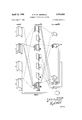
- Fig. 1' is a schematic wiring diagram of a switching system according to the invention for an exchange with separate selectors each having 100 outlets, which separate selectors are divided in each of the I-VII groups TK into three sub-groups of thirteen selectors each.
- the 100 outlets of the incoming selectors IK are divided among the seven groupsI-VII of the intermediate selectors TK, so that.
- Fig. 5 is third and preferred embodiment of a controller circuit and its connections through a switching system, also which may be adapted to a circuit similar to that shown in Fig. 1 or 2 of this invention.
- a switching system has been disclosed as comprising a plurality of selecting stages, namely an incoming selecting stage IX of groups of separate selectors, an intermediate selecting stage TK of groups of separate selectors, and a final selecting stage EK of groups of separate selectors.
- the banks of contacts of three or more of the groups of selectors of each stage are shown in perspective as arcuate surfaces, and the separate selector wipers are shown as arms which sweep over the vertically multipled contacts that lie in these surfaces of each group. All of the interconnecting lines and contacts are not shown for the reason of clarity, but only the first and last group of contacts of'each of the selectors are connected to the 7 corresponding wipers by lines in these circuits.
- final selectors three of which groups, namely 11, 25 and 00 are shown in Fig. 1. These selectors provide connections 1111 to 0000.
- about 270 cord circuits through the switching system shown in Fig. 1 would be sufiicient, so according to the 7 present embodiment there are shown 3 7 13 or 273 cord circuits which are connected from the incoming selectors IK through the intermediate selectors TK to the final selectors (each of these selectors also having 100 outlets).
- the intermediate selectors TK are herein multipled in seven groups I, II, III, IV, V, VI and VII, of which three, viz. I, III, and VII are shown.
- each group of intermediate selectors TK comprises incoming and intermediate selectors is such that the first sub-group of 13 of each of the seven intermediate selectors, is successively connected to the vertical rows of 1 through 13 contacts of the first incoming selector-1K; while the second sub-group of 13 selectors" of each of the seven intermediate selectors are connected to the vertical rows 1-13 contacts of the second incoming selector 1K; and similarly for the third sub-group of 13 to the third incoming selector.
- each of the 91 contacts'of each incoming selector are multipled to separate groups of wipers on each of the seven intermediate selectors TK.
- each outlet corresponds to one group of final selectors EK and each contact bank of switch BK corresponds to one of the seven final selectors of each group EK via a connection 25b.
- each controller circuit BC is multipled through a .cord finder KZ to the inputs of each of the incoming selectors IK, including the par- "rand "5 of this particular numberrzssa" being called, are successively sent overthe cord circuit 169'to the con troller circuit BC and the routing selector BK is moved to its th position, which motionis under the control of a register circuit C connected to one of the contact banks of the'cord' finder switch K2 and the stepping magnet BM of the selector BK This operation of the routing selector BK is done either directly or through a register circuit.
- Appropriate means is provided in the controller circuit BC of Fig. 1, 'as will'be described later in the controller circuits of Figs. 3, 4 and 5, so that a busy or idle condition of each of the seven final selectors of the group 25is ascertained via the route finding conductors 25b.
- the controller circuit BC thus has the task of starting the incoming selector IK to which the cord circuit 1601is connected, to let it hunt over the link groupsrunning from the inultipled contact banks of the middle incoming selector group to the wipers of themiddle subgroups of. 13 inthe 3rd and 7th groups of the intermediate selectors TK, in order to seize an idle intermediate selector there from. Any intermediate selector that can be seized under theseconditions is capableof completing the connection by simply occupying position 25 since each such intermediate selector is linked up with the 25-lllrd or the 25-Vllth final selector.
- the finalselector itself can then be positioned in accordance with the. last two digits 84" or the called subscribers number, either directly via the connections set up through the circuit of the incoming an'cl intermediate selectors as controlled by the con:
- ti'ollercircuit BC can control theincoming selector in a simple manner. For this purpose all of the intennfediate selectors maybe provided with special busy indicating,
- termediate selectors which circuits are indicated by the dotted lines 13a multipled to all 39 of the selectorsof each of the seven intermediateselector groups and then connected to the seven inputs or wipers, respectively, of the routing selector BK in the controller circuit BC.
- the conductors13a, energized through therouting selector BK, correspond with the finalselectors in the .desiredfinal selector group which are free and available, thus permitting the incoming selector for the chosen cord circuit (160) to pass over all of the occupied intermediate selecw tor groups of contacts in its bank. and only test for free selectors in the group or groups of intermediate selectors. through which a connection can be made to the desiredfinal selectors, namely intermediate selector groups TK- III and TK-Vll corresponding to the above assumed free.
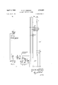
- theincoming selecting stage 1K is shown divided into four groups of fifty-six ISO-contact selectors and the intermediate selecting stage TK is divided into seven groups of forty lGO-contact selectors.
- only the first 70 of the 100 contacts of each selector of the incoming and intermediate selectors are employed, so that an extra contacts on each selector are available for reserve, such as for heavy traffic conditions.
- the circuit shown in Fig. 2 is only for 7000 subscribers, in that only separate final selector groups EK, each having 7 selectors, are employed.
- each said sub-group of ten selectors corresponds to a level or group of ten outlets of each multipled group of the incoming selectors.
- the first seventy outlets of the incoming selectors may comprise the first seven levels of two-motion selectors, and may be provided for local tratfic for which there are 280 intermediate selectors available.
- the chance for internal blocking in this portion of the, circuit is extremely small in view of the fact thatif 223' incoming selectors are already engaged, the 224th calling subscriber still finds 70-55: 15 free and available links in his group of 56 incoming selectors.
- the 8th, 9th and 10th or 0th levels of the incoming selectors IK of-Fig. 2 are utilized for other reserve pur the incoming selector and'determines the'position,
- level 10 may be for trunk lines and specialservices up to 10 lines.
- the additional group of final selectors a may be provided for heavy trafiic conditions, and ,may be multipled to those particular selectors for which heavy. trafiic is to be handled.
- routing selector may have, for one or each heavy traffic reserve group, a reserve position, such as for the final selector group 25a shown in Fig. 2, which is seized in V the case that the normal final selector group 25 is found completely busied.
- the incoming selector subsequently derives from the reserve position of such a routing selector in its corresponding controller circuit described above, the command to hunt for reserve links connected to the reserve group 25:1.(g1oups'25and 25a being connected in multiple as shown in Fig. 2) so that the calling subscriber will reach number 2584," as though he had dialed anumber, such as for example 9184..
- controller circuit directs the incoming selector, withoutthe intervention of the intermediate selecting stage, im-
- trunk circuits can be connected without withdrawing the reserve of the incoming selectors from the blocking chance reduction and/ or the completion of the heavy traific group, because the present system has been designed to take careof such trunk circuits.
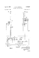
- a directlycontrolled controller circuit One of the simplest, although not a preferred controller circuit, is shown in Fig. 3 within the dot-dash lined rectangle. in this figure there are shown connected to each one of the seven busy indicating contacts 1-7 of p the final selector group 25, separate routing contacts of the routing selector BK, in which the contacts 3 and 7, corresponding to the unoccupied final selectors previously described in the example for Fig. l, are shown to 'be closed to ground.
- the routing selector BK indicating contacts ⁇ and 7 previously m'entione'd.
- only one controller circuit can be set into operation at the-time for controlling an'incoming selector. This is effected by means of the sequence relays VR of all the controller circuitspresent so that only one. relay VR can be energized at a time.
- the dependent means forthis control may comprise, for example, a testing-relay which after positioning the routing selector BK tests ,whether or not there 'are' routing, selectors in theother controller circuits. of other registers testing arou't:
- FIG. 4 Another development of the controller'circuit is shown in Fig. 4 in which .a smaller routing selector may be mployed than selector BK shown in Figs. 1 and ,3, namely the selector BK which has only one contact bank or row of contacts instead of 7 contact banks or rows of 100 contacts as selector BK.
- the controller circuit of this embodiment is based upon an open instead of a closed circuit condition of the busy indicating contacts 1'-7 of any one of the final selector groups, for example, final selector group 25. .Thus, when the routing selector of BK has arrived at the position 25 corresponding to the first two digits of the number being called as described in the example of Fig.
- a circuit is completed through a conductor 25" which is connected in parallel to all of the input contacts to final selectors'cf group 25.
- This controller circuitshown in Fig, 4 also discloses an addi tional' searching: switch OZ which is connected through a contact t to the wiper of the routing selector BK.
- the searching switch is provided with seven contacts, one corresponding to each selector of the separate seven selectors of each group of final selectors EK, and each of these seven contactsis multipled via conductors 25 to a" corresponding input of one final selector in each group.
- the marking switch MZ When the searching switch OZ occupies its third position (3) the marking switch MZ has also reached its third position (3) since their two wipers are coupled together as shown by the dotted line in Fig. 3. All the contacts of the marking switch MZ may be provided with different comparison voltages according to the taps of the potentiometer R2 supplied with voltage from a battery V4. These comparison voltages correspond with the comparison voltages of the marking outlets M0, which are a part of the incoming selector 1K. Thus, the incoming selector will be stepped according to the marking outlets M to its third position (3), under the control of the controller circuit and its marking switch M2.
- the voltages of the marking switches MZ and MO derived from potentiometers R1 and R2 through similar voltage sources V3 and V4, respectively, are compared in a Wheats'tone bridge circuit which is formed by the connection from the wiper M2 to the wiper MO through an auxiliary arc of contacts KZI) of the cord finder KZ.
- a testing device ET has been inserted which operates until a voltage balance is obtained, so that it then can stop the incoming selector by stopping its stepping magnet KM at the group corresponding to position (3).
- the incoming selector is then started again to find the idle link in the corresponding group III of intermediate selectors (not shown in Pig. 4).
- all the controller circuits can operate simultaneously. However, when the link group connecting the incoming selector to intermediate selector group III is busy, then the searching switch OZ in the controller circuit must be started once more in order to make another attempt to find a free connection via another final selector, namely, the final selector corresponding with routing contact 7 or 257', which is the other busy indicating contact opened as shown in Fig. 4.
- a preselecting controlled controller circuit According to Fig. 5, the last mentioned difficulty of the controller circuit of Fig. 4 is removed by the application of a switching path finder SZ.
- This switching path finder imitates momentarily the incoming selector and determines the position the lattershould take.
- the position of the incoming selector is then derived from the switching path finder by means of an independent controller device, such as for example: a Selsyn or servomotor, a bridging marking circuit, or switching method system according to a Wheats'ton'e bridge principle similar to that described in Fig. 4.
- the path finder SZ has three arcs or levels of seven contacts each, with three corresponding wipers, each connected to three groups of contacts on an auxiliary are or bank of contacts KZc of of the cord finder R2.
- the wiper of contacts KZc is connected to a second winding T2 of the testing relay for the searching switch OZ.
- the winding T2 of the testing relay may be energized by a battery V2, which may be common for all controller circuits, while a separatebattery V1 for each controller circuit is'connected to the routing-switch BK.
- Each testing conductor tests a whole link group, that is, all of the engaged sub-group of 13 intermediate selectors of a link group which have corresponding contacts connected inseries in said conductor, as shown schematically for theconductors 13b in Fig. 5 for only a part of the contacts or" the intermediate selector group TK-III.
- the last contact of each series of 21 conductors is grounded as shown at the upper end of the wires 13b in Fig. 5.
- path finder SZ finds ground potential on the relevant testing conductor indicating that that particular sub-group of 13' selectors is occupied and another sub-group must be found.
- the auxiliary arc of contacts KZc of the cord finder KZ insures that the ground potential from all the occupied TK-lii sub-group of selectors reaches the winding T2 of the testing relay, whereby the armature t" of which relay may remain as a consequence thereof in its forward position regardless of the open circuit through contact (3) of the searching switch OZ, operated as described in the previous chapter II2 for Fig. 4. Accordingly, the searching switch OZ still continues to step on until it reaches its position (7) corresponding to final selector 25-7', which is also shown to have an open circuit in Figs. 4 and 5; it being the only other final selector which is available in the group 25. Thus, the stepping of the searching switch OZ is continued without first starting the incoming selector iii to test the position Ill and awaiting a failure, as is necessary in the previous embodiment described in connection with Fig. 4. I
- the incoming selector may be started in the meantime without waiting for the stopping of the searching switch OZ under the control of the bridge marking switches MZ and MO, since the motion of MO must follow the movement of the marking switch MZ connected to the wiper of the searching finder OZ as Well as the wipers of each of the three arcs of contacts of the path finder SZ (see connection indicated by a dotted line shown in Fig. 5).
- searching switch OZ marking switch M2
- the switching path finding switches 82 are represented as separate units, they will preferably be combined as a collective selector switch, with two levels as shown in Fig. 4, or with five or more levels as shown in Fig. 5.
- S2 and M2 has only seven, or in a heavy traflic exchange a possible ten positions, it operates very rapidly after the positioning of the routing selector BK.
- a switching path finder 52 as shown in Fig. 5 it is possible to lay out completely, in the shortest possible time, the route to he followed through the exchange.
- the three groups ofselectors that is 1K, TX and EK, can be put into operation simultaneously, which permits a material saving of time.
- the position of the incoming selector TX is entirely defined or determined by that of the marking switch MZ and the idle intermediate selector chosen from the indicating link groups.
- the intermediate selector TK derives its position 25 from the routing selector BK, or from a register on which the first two digits have been recorded.
- the final selector EK derives its position from a register on which the last two digits of the number called (84) have been recorded.
- any one of the controller circuits shown in the dot-dash lined rectangles in Figs. 3, 4 and 5, may
- the system of the present invention has many 7 digit system is employed can operate according to the same diagram as that shown in advantages and enables an automaticswitching exchange 'to takefcare of an increased number of 'calls with a relatively small number of selector switches, as well as being ableto avoid the necessity of also providing register circuits which may be replaced at least in part by the particular controller circuit shown in Fig. 5 of this invention.
- an impulse responsive switching system having at least three consecutive selecting stages, each of which stages has a plurality of groups of selector switches with each switch having an input and a plurality of outputs, and said system also having groups of conductors for connecting each input of each group of selector switches of a subsequent stage in multiple with some of the outputs of each group of the selector switches of a previous stage, the improvement comprising: a controller circuit connected to the inputs of the selector switches of the final of said consecutive selecting stages to preselect a free and available final selector to which a connection can be made through said previous stages of said system under the control of said controller circuit, said controller circuit being responsive to a plurality of impulses to set up a connection and including a routin'gselector respon sive'to the impulses preceding the ones used for setting the final selector and corresponding to a desired final selector output.
- an impulse responsive switching system having at least three consecutive selecting stages, each of which stages has a plurality of groups of selector switches, and each selectorswitch has an input and a plurality of outputs
- the improvement comprising: a route determining contact associated with at least the final stage for indicating the busy condition of said selectors, and a controller circuit responsivelto a plurality of impulses for setting up a connection, comprising: a routing selector connected to said route deter mining contacts responsive to the impulses preceding the V ones used for setting said final selector corresponding to a desired final selector output, a finder means connected to the inputs of the selector switches of the first. stage,
- a testing device to determine by means of said routintermediate selector switches and a plurality of final selector switches, forconnecting simultaneously a plurality of different circuits from said incoming selector switches to the desired onesof said final selector switches, each of said selector switches having an input and a plurality of outputs, the improvements comprising: X number of groups of incoming selector switches, Y number.
- said controller circuit being responsive to a plurality of impulses to set up a connection and including'a routing selector responsive to the impulses preceding'the ones used for setting the final selector switches and corresponding to the desired final selector output.
- selecting stages being provided with selectors each having an inlet and a plurality of outlets; a controller circuit provided with a cord finder having a plurality of contacts and responsive to a plurality of said impulses for setting up a connection; a number of incoming lines each being connected to the inlet of an incoming selector as:well as to a contact of said cord finder, the selectors of all selecting stages being divided into groups having.
- an automatic impulse responsive switching system comprising at least three stages of groups of selector switches having a first stage, an intermediate stage or stages, and a final stage of selectors, each of which selectors has an input and a plurality of outputs
- the improvement comprising a controller circuit responsive to a plurality of impulses for setting up a connection comprising: a routing selector having an input and a plurality of output contacts and responsive to the impulses preceding the ones used for setting said final selectors, means connecting said routing selector output contacts to the inputs of said final selectors, and means connecting said input of said routing selector to the inputs of each of said groups of intermediate selectors, whereby said controller circuit pre-selects a free final selector to which said first and intermediate selectors must be routed.
- a controller circuit comprising: a routing selector having an input and a plurality of output contacts positioned by the first of the digits transmitted to said system, means connecting said routing selector output contacts to the multipled inputs of the final selectors of each group of final selectors, and means connecting the input of said routing selectors to the multipled groups of inputs of corresponding final selectors from each group of final selectors, whereby said controller circuit pre-selects a free final selector to which said first and intermediate selectors must be routed.
- I 13 In an automatic switching system between a plurality of calling and called stations, having an incoming stage, an intermediate stage and a final stage of groups of selector switches, each selector switch having an input and a plurality of outputs, and said system also having a plurality of multipled output terminals of one group of selectors of a preceding stage being connected to the input terminals of at least one selector of each group of a following stage, the improvement comprising a controller circuit comprising: a first means for connecting said controller circuit to the input of any one of said selectors of said incoming stage, a second means for connecting said controller circuit to said inputs of at least said final selector switches in said final selector stage, and'a routing selector in said controller circuit positioned according to the digits of the called station, whereby said controller circuit can pre-select the free selectors, one in each stage from said final stage back to said incoming stage, that are to be positionedfor completing a connection through said system between a calling and called station.
- a controller circuit comprising: a first means for connecting said controller circuit to the input of any one of the selectors of said incoming stage, a second means for connecting the controller circuit to said input of said finalselector stage, and third means for connecting said controller circuit to said input of an in termediate selecting stage, and a routing selector in said controller circuit positioned according to the digits of the called station, whereby s aid controller circuit can preselect the free selectors, one in each stage from said final stage back to said incoming stage, and
- a switching system comprising: a first or incoming selecting stage,'an intermediate selecting stage, and a final selecting stage, each of said selecting stages being provided with selectors each having an inlet and a plurality of outlets, said system having a selector in each stage to be positioned according to the digits of a called final selector outlet, a controller circuit provided with a cord finder having a plurality of contacts, a number of incoming lines each being connected to the inletof an incoming selector as well as to a contact of said cord finder, groups of conductors connecting the selectors of all the selecting stages and dividing said selectors into multipled groups, the resulting multipled groups of selector outlets of each preceding selector stage being connected to the inlets of each of the groups of multipled selector s of the following selecting stage; a routing selector in said controller circuit, said routing selector comprising a number of sections, routing contacts associated with the inlets of each intermediate and final selector, means connecting corresponding sections ofthe routing selector with the routing contacts of the
- a switching system comprising: a first or incoming selecting stage, an intermediate selecting stage, a final selecting stage, each of said selecting stages being provided with selectors each having an inlet and a plurality of outlets, and each of said inlets of said final selectors having also a two terminal routing contact; said system having a selector in each stage to be positioned according to the digits of a called final selector outlet; a controller circuit provided with a cord finder having a plurality of contacts and a routing selector having inputs and outputs, a number of incoming lines each being connected to a contact of said cord finder and to an inlet of an incoming selector; groups of conductors connecting and dividing each selecting stage into groups of multipled sellectors, the multipled selector outlets of each preceding selecting stage being connected to the inlets of each of the groups of multipled selectors of the following selecting stage, said routing selector having a number of'outputs equal to the number of groups of selectors in the final selecting stage with each outlet of said routing select
- a switching-system comprising: a first or incomingselecting stage provided with selectors having inlets and a plurality of outlets in contact banks; an intermediate selecting stage and a final selecting stage, each being provided with selectors each having a plurality of outlets in a contact bank, and each having an inlet having a wiper and a routing contact; said system having a selector in each stage to be positioned according to the digits of a called final selector outlet; a controller circuit provided with a routing device and a cord finder having a plurality of contacts; a number of incoming lines each being connected to a contact of said cord finder and to an inlet of anincoming selector, groups of conductors connecting and dividing each selecting stage into groups of multipled selectors, the multipled selector outlets of each-preceding selecting stage being connected to inlets of each of the groups 'of multipled selectors of the following selecting stage; said routing device including first, secondv and third sections having separate wipers and contact banks, respectively, the contacts of
- the improvement comprising a controller. circuit comprising a routing selector having a plurality of inputs and a plurality of output contacts whichrselector is'positioned by the first of the digits transmitted toisaid system, means connecting said routing selector contacts to the: 7 inputs of a group of final selectors, and means connecting the inputs of said routing selector tothemultipled outputs of each of said groups of said first selectors, whereby said controller circuit preselects a free final selector to which said first and intermediate selectors must be routed.
- a switching system comprising: a first or incoming contacts; a number of incoming lines eachfbeing connected to a contact of said cord finder and to an inlet of an incoming selector, groups of conductors connecting and dividing each selecting stage into groups of multipled selectors, the multipled, selector outlets of each preceeding selecting stage'being connectedto'inlets-of each ofthe groups of multipled selectors of the following selecting stage; said routing device including first, second and third sections having separate wipers and contact banks, respectively, the contacts of saidls'econd contact bank being connected in multiple to the routing contacts 7 of said final selectors, respectively, means for moving'the wipers of said second and said third sections jointly, said 7 first section being positioned according'to the first series of digits received over a calling incoming line to select the wanted group of final selectors and multipledrouting contacts thereof, and a means connected between the first and second wipers of therouting device operative when said second section finds a free final selector in the wanted group
Landscapes
- Engineering & Computer Science (AREA)
- Computer Networks & Wireless Communication (AREA)
- Use Of Switch Circuits For Exchanges And Methods Of Control Of Multiplex Exchanges (AREA)
- Exchange Systems With Centralized Control (AREA)
Description
April 10, 1956 R. M. M. OBERMAN AUTOMATIC SWITCHING SYSTEM 5 Sheets-Sheet 1 Filed June 7, 1951 100x? EK nssTK CONTROLLER c l Rcurr Flilil- 1 INVENTOR: RM M UBZ'RMA'N.
JTTYT April 956 R. M. M. OBERMAN 2,741,663
AUTOMATIC SWITCHING SYSTEM Filed June 7, 1951 5 Sheets-Sheet 2 MsslK n4o-2eoTK TOJ-AQOEK i 56: I I l 11 i I: as E I I I I I I/ D70 mm l 56E EliZSa so FIG.2
INVENTOR: RMM. UBEHMAN.
ATTY'.
April 10, 1956 R. M. M. OBERMAN AUTOMATIC SWITCHING SYSTEM 5 Sheets-Sheet 3 Filed June '7, 1951 I CONTROLLER k {CIRCUIT I l I l I J FIG. 3
INVENTOR. RMM. UBEHMAN.
BY I
ATTY.
April 10, 1956 R. M. M. OBERMAN AUTOMATIC swrrcmuc SYSTEM 5 Sheets-Sheet 4 Filed June 7, 1951 STEPPING M {MAGNET IN VEN TOR: 12. M. M. UBEHMAN.
ATTY.
April 10, 1956 R. M. M. OBERMAN AUTOMATIC SWITCHING SYSTEM 5 Sheets-Sheet Filed June 7, 1951 ATTY.
United States Pate-Ire 9 AUTOMATIC SWITCHING SYSTEM Roelof Maarten Marieohernran, The Hague, Netherlands, assignor to De Staat der'Nederlanden, Ten Deze Vertegenwoordigd Door de Directeur-Generaal, der
Posterijen, Telegraphic-en Tlefo nie, The Hague, Neth This invention relates to an automatic switching system for telephony, telegraphy and the like. More particularly, it deals with the switch ng system for preselecting a given one of a plurality of lines, leading from an exchange to a subscriber, such as by means of successivegroups of se: lectors.
In many previously known switchingsystems, the occurrence of many noneavailable switching paths cannot be avoided due to the directionahselection of the grup,selectors of such asystem. This results in traflic restrictions and can only be overcome by divided multiple fields, such as grading or slipping connections for groupsof selector switches and/ or expensive selectors having many outlets, such as cross-bar and'panel selectors.
It is an object of this invention to produce a simple, economic, efficient and effective automatic switching system whereby a greaternumber of. calls can. be made through a given number of selectors, or thereduction in the number of intermediate selectors can be accomplished.
Another object is to provide an automatic switchingselecting system wherein. a free path through a series of group selectors is predetermined'for each subscribers line being called.
Another object is to provide an automatic switching see lecting system in which each final selector may be reached through any fully available groups of lines- Another object is toprovide a selector circuitpro vided witha plurality of incominginterrnediate, andfinal selectors in which the number of intermediate selectors is equal to the number of incoming selectors and'much smaller than the number of final selectors, wherebyior example, in the case of weak trafiic condition a. multiple group of seven final selectors per 100 connections is sufiicient. a 4
Another. object isto provide a switching system comprising a plurality of selectors for'selecting' final selectors in which the problems of grading and slipping .are not encountered. i
Another objectis to provide a controller circuit which bridges the incoming and intermediate selecting stages of a three stage selector switching system for routing the calls through available incomingand intermed ateQSelectors Which have accessto an idle and desiredfirral selector. w c
Another object .of this invention is to provide such controller circuits for a selecting system which may operate simultaneously to complete several connections.
Another object is to provide a switching system com: prising a plurality of stages .of selectors having free out lets to provide for extensions and reserves. K
Another object is to provide a switching system which ofiers a great freedom of action with regard to the extension of the system, giving a maximum of facilities with aminimum number, of selectors.
Generally speaking, the system of this invention comprises at least three separate selecting stages each of which is provided with groups of selector switches. All oi selector switches of each groupv are provided with 'wipets 2,741,663 Patented Apr. 10, 1956 andcontact banks. The selectors of each stage are dividedinto groups of multipled selectors, and the contact bank of each preceding selector is trunked out to the inputs or wipers'of each of "the succeeding selectors in the followingselec'ting stage; K Thus, the multipled contact banks of the 'selectorsin any one stage are divided to correspondto thenumb'e'r of selectors in the following selectstage. l'naddition to this connection, there is also provided a controller circuit connected between the incoming 'selector stage and'the final selecting stage, which hunts for a free path through the selecting stages of the switching system.- This is accomplished by providing a routing selector in the controller 'circuit responsive to those digits of the called number prior to the digits for positioning the final selector, which first seeks out the particular final selector groups and then sets up the preceding selecting stages corresponding to the first digitsof the number called. This is'ac'complishcd by testing each of the final selectors of the group selected to find which one is free, and then connecting thereto those preceding selectors having access to that free final selector. Thus, numerical selection through the controlling circuit precedes hunting of the proper circuit through the switching system, so thatthe incoming selector picks an intermediate selector known beforehand to be free and available for through connection to the preselected final selector. Accordingly, the controller circuit cooperating with the incoming'and intermediate selector stages en ables these selectors together to act as a large capacity group selector. k
Thus, according to the present invention, any incoming junction may be connected to any intermediate selector group andto any outgoing junction. As a con sequence, for example, the incoming selecting stage of selectors with outlets and the intermediate selecting stage of selectors with lOO-outlets are equivalent to a single group selector'stage in which each selector has 10,000 outletsi c The controller circuit may be included in each register circuit of the systemzand comprises relays, contacts, connections, rectifiersor batteries, etc. that are connected to. the wipers of 'theselectors of'both' the-intermediate andxthe finalselecting. stages,=and through a cord finder type. of selector: switch-i for selecting cord-or connecting circuits to the input'wipers of the selectors of theincoming selecting stage, as well as means for testing which lines in the final selectors are busy. There also may be included switching devices in the controller circuit which may be connected to the trunk lines connecting the wipers of the selectorsof the intermediate selecting stage, as well as the final s'electings'tage of the switching system. If therfinal selectors were under the influence of the controller circuit without testing the incoming. side of the. final selector as in the case of a cross-bar system, the efiect of this invention wouldlbecome impossible. There fore, in the cross-bar system, selection is effected nonnumericall-y. in all selecting stages so that the controller circuit has amuch more complicated function to perform.
This gives riseto restrictionsin the number of controller 7 circuits .in useisimultaneously, which restrictions originate from switching consideration's'as well as being of an economic nature. These restrictions do not exist in the systern according to the present invention. An exchange according to the present invention is provided with the full number of controller circuits required by the probability'cornputation, and these controller circuits are capable of operating simultaneously for the completion of several connections.
The .a bovejmentioned and other features and objects of this invention and the manner of attaining them are given more specific disclosure in the following description of embodiments of the invention taken'in' conjunction with V the accompanying drawings,'wherein:
. Fig. 1' is a schematic wiring diagram of a switching system according to the invention for an exchange with separate selectors each having 100 outlets, which separate selectors are divided in each of the I-VII groups TK into three sub-groups of thirteen selectors each.
The 100 outlets of the incoming selectors IK are divided among the seven groupsI-VII of the intermediate selectors TK, so that.
or 13 links to each sub-group of the seven groups of in-' termediate selectors. There may be three separate groups of incoming selectors IK, of which each selector in each bodiment of a controller circuit and its connections, which may be adapted to a circuit similar to that shown in Fig.
7 l or 2 of thisinvention; and
Fig. 5 is third and preferred embodiment of a controller circuit and its connections through a switching system, also which may be adapted to a circuit similar to that shown in Fig. 1 or 2 of this invention.
In Figs. 1 and 2 a switching system has been disclosed as comprising a plurality of selecting stages, namely an incoming selecting stage IX of groups of separate selectors, an intermediate selecting stage TK of groups of separate selectors, and a final selecting stage EK of groups of separate selectors. The banks of contacts of three or more of the groups of selectors of each stage are shown in perspective as arcuate surfaces, and the separate selector wipers are shown as arms which sweep over the vertically multipled contacts that lie in these surfaces of each group. All of the interconnecting lines and contacts are not shown for the reason of clarity, but only the first and last group of contacts of'each of the selectors are connected to the 7 corresponding wipers by lines in these circuits. The controller circuit which is one of the principal features of this invention, is shown in Figs. 1, 3, 4 and 5 within a dotdash lined rectangle. Any one of these controller circuits may be interchanged with any one of the other circuits shown, to form difierent embodiments within the scope of this invention. Only those parts for each controller circuit which difier from that shown in Fig. 1 are shown in Figs. 3, 4 and 5; that is, the register circuits and congroup has 100 outlet contacts, and each group of which may comprise 91 separate selectors, namely 7X13; and the three groups of 91 selectors being 3 9l=273, providing the number of originally required cord circuits which are connected to the wipers of the incoming selectors IK. The banks of the 100 contacts of each of the incoming selectors, however, are divided among the inter- V mediate selectors in such a way that 7 l3=91, or only 91 of the 100 contact points of each selector are employed, thus leaving 9 extra contacts on each incoming selector for reserve purposes as will be described later; In this particular arrangement a division of selectors between the trol devices C and BM in Fig. 1, which include the controls for the stepping magnets for operating the selector switches both in the control circuit BC itself and in the selecting stages, are not repeated in Figs. 2,3, 4 and 5, since such circuits and control devices are conventional and not a part of the inventive feature of this system.
I. THE SWITCHING SYSTEM IN GENERAL Referring to Fig. .1, it is assumed for the purpose of illustration that the final selectors EK, each have a bundred outlets and are multipled in groups of seven, so that 'for a 10,000 line exchange there are 100 groups of seven.
final selectors, three of which groups, namely 11, 25 and 00 are shown in Fig. 1. These selectors provide connections 1111 to 0000. In the case of a light trafiic exchange, about 270 cord circuits through the switching system shown in Fig. 1 would be sufiicient, so according to the 7 present embodiment there are shown 3 7 13 or 273 cord circuits which are connected from the incoming selectors IK through the intermediate selectors TK to the final selectors (each of these selectors also having 100 outlets). The intermediate selectors TK are herein multipled in seven groups I, II, III, IV, V, VI and VII, of which three, viz. I, III, and VII are shown. The number of groups of mtermediate selectors accordingly should correspond to the tors IK, that is 273, each group of intermediate selectors TK comprises incoming and intermediate selectors is such that the first sub-group of 13 of each of the seven intermediate selectors, is successively connected to the vertical rows of 1 through 13 contacts of the first incoming selector-1K; while the second sub-group of 13 selectors" of each of the seven intermediate selectors are connected to the vertical rows 1-13 contacts of the second incoming selector 1K; and similarly for the third sub-group of 13 to the third incoming selector. Thus,'each of the 91 contacts'of each incoming selector are multipled to separate groups of wipers on each of the seven intermediate selectors TK.
The numerical division of the selectors between the incoming and intermediate selectors, however, may be adapted for difierent types of selector switches. If the use of l3links per group is diflicult, such as in the case of a two motion selector of 10x10, the size of the link groups can be reduced to 9 or 10 links by dividing the incoming selecting stage into four groups of about 68 incoming selectors each, but then 7 l0=70, or only 70 of the outlets of each of the incoming selectors are used. This provides an additional plurality of reserve contacts on the incoming selectors, which will be described later in the description of Fig.2, and is advantageous for circuits having heavy tratfic.
1. A light traffic system Let it be assumed that the th cord circuit has been seized by a call for a subscribers number 2584, for
V which there is a corresponding line from the final selector group 25 as shown at'2584 in Fig. 1. This connection must be reached through one of the seven selectors of the final selector group 25,- each one of which selectors is connected to a different intermediate selector TK. The
problem now is: which of the intermediate selectors TK' is the one which is to be chosen? This problem is solved by the controller circuit BC'shown in the dot-dash rectangle at the bottom of Fig. 1, and which may be replaced by any one of the similar controller circuits in dot-dash rectangles'shown'in Figs. 3-5 described later. However, for the purpose of aquick description of operation of Fig. 1, it will only be considered that the present controller circuit comprises a routing selector BK, and additional means not shown in the circuit BC for the control of this routing selector. As shown in'Fig. 1, the seven contact banks of 100 outlets each from the routing selector BK are multipled to each of the inputs of the final selectors, so that each outlet corresponds to one group of final selectors EK and each contact bank of switch BK corresponds to one of the seven final selectors of each group EK via a connection 25b. Also each controller circuit BC is multipled through a .cord finder KZ to the inputs of each of the incoming selectors IK, including the par- "rand "5 of this particular numberrzssa" being called, are successively sent overthe cord circuit 169'to the con troller circuit BC and the routing selector BK is moved to its th position, which motionis under the control of a register circuit C connected to one of the contact banks of the'cord' finder switch K2 and the stepping magnet BM of the selector BK This operation of the routing selector BK is done either directly or through a register circuit. Appropriate means is provided in the controller circuit BC of Fig. 1, 'as will'be described later in the controller circuits of Figs. 3, 4 and 5, so that a busy or idle condition of each of the seven final selectors of the group 25is ascertained via the route finding conductors 25b.
'Let us assume that the third and 'seveiith final selectors of the group 25, namely 25lll and 25-Vll are idle. The controller circuit BC thus has the task of starting the incoming selector IK to which the cord circuit 1601is connected, to let it hunt over the link groupsrunning from the inultipled contact banks of the middle incoming selector group to the wipers of themiddle subgroups of. 13 inthe 3rd and 7th groups of the intermediate selectors TK, in order to seize an idle intermediate selector there from. Any intermediate selector that can be seized under theseconditions is capableof completing the connection by simply occupying position 25 since each such intermediate selector is linked up with the 25-lllrd or the 25-Vllth final selector. The finalselector itself can then be positioned in accordance with the. last two digits 84" or the called subscribers number, either directly via the connections set up through the circuit of the incoming an'cl intermediate selectors as controlled by the con:
troller circuit, or by means of a register circuit if a complete register is employed.
If the incoming selectors IK have contact banks with 100.contactsin uninterrupted sequence, so that thegroups 0113 link's asishown' in Fig. 1 can be employedjthe. con-.
ti'ollercircuit BC can control theincoming selector in a simple manner. For this purpose all of the intennfediate selectors maybe provided with special busy indicating,
or routing contacts in each of the input circuits of the in:
termediate selectors, which circuits are indicated by the dotted lines 13a multipled to all 39 of the selectorsof each of the seven intermediateselector groups and then connected to the seven inputs or wipers, respectively, of the routing selector BK in the controller circuit BC. The conductors13a, energized through therouting selector BK, correspond with the finalselectors in the .desiredfinal selector group which are free and available, thus permitting the incoming selector for the chosen cord circuit (160) to pass over all of the occupied intermediate selecw tor groups of contacts in its bank. and only test for free selectors in the group or groups of intermediate selectors. through which a connection can be made to the desiredfinal selectors, namely intermediate selector groups TK- III and TK-Vll corresponding to the above assumed free.
scribed later. This switching path finder imitates momenfi f the latter sho'uld takej 2. Aheavy trqjfic system if the incoming selectors 1K are for instance two-motion selectors, the 1st, 2nd, 4th, 5th and 6thlevel should be made'inaccessible' during the vertical hunting movement according to the specific example described in the chapter I(l above; and in the case the 3rd level too should be inaccessible, the selector needvnot be unnecessarily hunt over it either. A corresponding explanation applies to selectors in which the selection of one of a plurality of different levels is afiected by a trip spindle as V in rotary selector switches (see page 266, vol. 3. of Telephone Theory and Practice, Automatic Switching and Auxiliary Equipment by Kempster B. Miller, published by McGraw Hill & Co., 1933).
Thus according to Fig, 2, for heavy tratfic .theincoming selecting stage 1K is shown divided into four groups of fifty-six ISO-contact selectors and the intermediate selecting stage TK is divided into seven groups of forty lGO-contact selectors. This greater number of intermediate selectors TK (7 4()'=280) than of incoming selectors IK'(4 56=224) diminishes the chances for internal blocking. In this embodiment only the first 70 of the 100 contacts of each selector of the incoming and intermediate selectors are employed, so that an extra contacts on each selector are available for reserve, such as for heavy traffic conditions. However, the circuit shown in Fig. 2 is only for 7000 subscribers, in that only separate final selector groups EK, each having 7 selectors, are employed.
The intermediate seven groups of selectors TK'ar'e ac cordingly divided into four sub-groups of ten selectors,
and each said sub-group of ten selectors corresponds to a level or group of ten outlets of each multipled group of the incoming selectors. Thus the first seventy outlets of the incoming selectors may comprise the first seven levels of two-motion selectors, and may be provided for local tratfic for which there are 280 intermediate selectors available. The chance for internal blocking in this portion of the, circuit is extremely small in view of the fact thatif 223' incoming selectors are already engaged, the 224th calling subscriber still finds 70-55: 15 free and available links in his group of 56 incoming selectors.
In connection with the known literature about internal blocking in link systems, it is easy to show that the inter-v rial blocking in the embodiments of this invention is negligibly small with respect to the external blocking. If necessary all of the positions of the incoming selectors shown in Figs. 1 and 2 can be used instead of only the 91 and 70 shown, respectively, so that of the system of Fig. 1, and
or about 57 intermediate selectors in one group of the system of Fig. 2. If the occurrence of groups of heavy trafiic subscribers is to be expected when composing an exchange, without knowledge beforehand of the subscribers belonging to such groups, space must be left in each bay of conventional systems for mounting reserve final selectors in each final selector group. In the system according to the present invention, however, all the bays can be arranged for seven final selectors, and all reserves may be located in separate bays. Accordingly, the reserve possibility for extremely heavy trafiic groups is fundamentally unlimited.
The 8th, 9th and 10th or 0th levels of the incoming selectors IK of-Fig. 2 are utilized for other reserve pur the incoming selector and'determines the'position,
' poses. For example, levels 8, 9 and as follows: levels 8 and 9 (multipled over all of the 10.may be divided incoming selectors) may be connected directly to 20 final selectors'bound for extremely heavytrafiic groups, and
.level 10 (orO) may be for trunk lines and specialservices up to 10 lines.
Since there are only 7000 final outlets to the 70 difin the controller circuit has reached its position 25* corresponding to the first two digits of the number to be routed through'the circuit of Fig. 1, wipercontacts 3 and 7 of BK are grounded through the corresponding busy;
ferentgroups of final selectors, the numbers 8111 and subscribers numbers 8111 to 8000; level 9 for heavy traffic groups'for which'up to 70 final selectors can be provided in additional bays; and level 10 (or for up to 70 trunk lines. 7
The additional group of final selectors a, and the other groups shown in the lower part of the final selector stage EK of Fig. 2, may be provided for heavy trafiic conditions, and ,may be multipled to those particular selectors for which heavy. trafiic is to be handled. A
' routing selector may have, for one or each heavy traffic reserve group, a reserve position, such as for the final selector group 25a shown in Fig. 2, which is seized in V the case that the normal final selector group 25 is found completely busied. The incoming selector subsequently derives from the reserve position of such a routing selector in its corresponding controller circuit described above, the command to hunt for reserve links connected to the reserve group 25:1.(g1oups'25and 25a being connected in multiple as shown in Fig. 2) so that the calling subscriber will reach number 2584," as though he had dialed anumber, such as for example 9184..
Another possibility is to use reserve links for trunk traffic. In this case, at least one of the numbered posi; tions, that is 0 for example of a routing selector in a controller circuit, must be reserved for this purpose, and
consequently at least one of the 100 final selector groups for local trafiic should be omitted. If 0 is chosen, the
controller circuit directs the incoming selector, withoutthe intervention of the intermediate selecting stage, im-
mediately to the'trunk circuit. This method, however, is not recommended since by abandoning a final selector group for local tralfic, a position falls open in each ofthe intermediate selectors. On the other hand, by including the trunk traflic selectors together with these selectors, trunk circuits can be connected without withdrawing the reserve of the incoming selectors from the blocking chance reduction and/ or the completion of the heavy traific group, because the present system has been designed to take careof such trunk circuits.
It may seem more rational to serve all the heavy tratfic groups via the intermediate selector reserves and to derive II. THE CONTROLLER CIRCUITS V l. A directlycontrolled controller circuit One of the simplest, although not a preferred controller circuit, is shown in Fig. 3 within the dot-dash lined rectangle. in this figure there are shown connected to each one of the seven busy indicating contacts 1-7 of p the final selector group 25, separate routing contacts of the routing selector BK, in which the contacts 3 and 7, corresponding to the unoccupied final selectors previously described in the example for Fig. l, are shown to 'be closed to ground. Thus, when the routing selector BK indicating contacts} and 7 previously m'entione'd. When the sequence relay VR, shown in the controller circuit, is energized, the conductors 3 and 7 are connected to the intermediate selector groups HI and VII, and the incom-- ing selector 1K finds ground potentials on groups III and VII. In' Fig. 3 there is also shown for group I of tie intermediate selectors TK, a closed routing contact connected by one of the trunk lines 13a through the controller circuit, but the routing conductor connected to it is not grounded by the corresponding closure of the busy indicating contact 1 of the final selector 25, so that the incoming selector is not stopped at group TK-I. Thus,
as the incoming selector searches over the intermediate selectors TK it can only be stopped at the intermediate selector groups III' and VII. if one of their selectorshas a closed routing contact to complete a circuit to ground.
Accordingly, since all of the routing contacts of the intermediate selectors of group TK-III are shown to be open, the incoming selector for cord circuit 160 only; stops at intermediate selector group TK-VII.
In this embodiment only one controller circuit can be set into operation at the-time for controlling an'incoming selector. This is effected by means of the sequence relays VR of all the controller circuitspresent so that only one. relay VR can be energized at a time. The dependent means forthis control may comprise, for example, a testing-relay which after positioning the routing selector BK tests ,whether or not there 'are' routing, selectors in theother controller circuits. of other registers testing arou't:
ing-at that time, and if'not, the sequence relay of the involved control circuit'is operated. 'The positioning of the cord finder KZ,jand*the routing selector BK, shown in Fig. 3, is efiected independentlygof the other controller 2. A balanced contr lled controller circuit:
Another development of the controller'circuit is shown in Fig. 4 in which .a smaller routing selector may be mployed than selector BK shown in Figs. 1 and ,3, namely the selector BK which has only one contact bank or row of contacts instead of 7 contact banks or rows of 100 contacts as selector BK. The controller circuit of this embodiment is based upon an open instead of a closed circuit condition of the busy indicating contacts 1'-7 of any one of the final selector groups, for example, final selector group 25. .Thus, when the routing selector of BK has arrived at the position 25 corresponding to the first two digits of the number being called as described in the example of Fig. l, a circuit is completed through a conductor 25" which is connected in parallel to all of the input contacts to final selectors'cf group 25. This controller circuitshown in Fig, 4 also discloses an addi tional' searching: switch OZ which is connected through a contact t to the wiper of the routing selector BK. The searching switch is provided with seven contacts, one corresponding to each selector of the separate seven selectors of each group of final selectors EK, and each of these seven contactsis multipled via conductors 25 to a" corresponding input of one final selector in each group. V
' contacts t, wiper OZ, a search conductor 25', one of the rectifiers 25 at the inputs to the selectors of group 25,
a corresponding closed contacts 1' of final selector 25, routing conductor 25", wiper BK, batteryV (a separate one for each controller circuz'"), rectifier G1 and back to Winding T. In position 3 the searching switch OZ finds busy indicating contact 3' in the final selector group 25 open, so that the test relay T now releases and interrupts the circuit to stop switch OZ from stepping by deenergizing the power magnet OM connected through another contact 2' of relay T. Via the back contact of armature t the final selector 254:, which has just been found'to be free, is now provisionally busied, since armature t is connected in parallel to the routing contact 3' of group 25, so that another controller circuit of the system hunting over the group 25 will find contact 3' already busied, which. indication is held until a connection to its corresponding final selector is completed.
When the searching switch OZ occupies its third position (3) the marking switch MZ has also reached its third position (3) since their two wipers are coupled together as shown by the dotted line in Fig. 3. All the contacts of the marking switch MZ may be provided with different comparison voltages according to the taps of the potentiometer R2 supplied with voltage from a battery V4. These comparison voltages correspond with the comparison voltages of the marking outlets M0, which are a part of the incoming selector 1K. Thus, the incoming selector will be stepped according to the marking outlets M to its third position (3), under the control of the controller circuit and its marking switch M2. The voltages of the marking switches MZ and MO derived from potentiometers R1 and R2 through similar voltage sources V3 and V4, respectively, are compared in a Wheats'tone bridge circuit which is formed by the connection from the wiper M2 to the wiper MO through an auxiliary arc of contacts KZI) of the cord finder KZ. In this connection a testing device ET has been inserted which operates until a voltage balance is obtained, so that it then can stop the incoming selector by stopping its stepping magnet KM at the group corresponding to position (3). The incoming selector is then started again to find the idle link in the corresponding group III of intermediate selectors (not shown in Pig. 4). These two selective motions may be combined when all the idle intermediate selectors of group lII are marked by the same marking voltage (3).
In this embodiment, all the controller circuits can operate simultaneously. However, when the link group connecting the incoming selector to intermediate selector group III is busy, then the searching switch OZ in the controller circuit must be started once more in order to make another attempt to find a free connection via another final selector, namely, the final selector corresponding with routing contact 7 or 257', which is the other busy indicating contact opened as shown in Fig. 4.
3. A preselecting controlled controller circuit According to Fig. 5, the last mentioned difficulty of the controller circuit of Fig. 4 is removed by the application of a switching path finder SZ. This switching path finder imitates momentarily the incoming selector and determines the position the lattershould take. The position of the incoming selector is then derived from the switching path finder by means of an independent controller device, such as for example: a Selsyn or servomotor, a bridging marking circuit, or switching method system according to a Wheats'ton'e bridge principle similar to that described in Fig. 4.
According to the circuit in Fig. 5, the path finder SZ has three arcs or levels of seven contacts each, with three corresponding wipers, each connected to three groups of contacts on an auxiliary are or bank of contacts KZc of of the cord finder R2. The wiper of contacts KZc is connected to a second winding T2 of the testing relay for the searching switch OZ. The winding T2 of the testing relay may be energized by a battery V2, which may be common for all controller circuits, while a separatebattery V1 for each controller circuit is'connected to the routing-switch BK. The 3 X 7=21 contacts of the switching path finder 82 are connected to 21 testing conductors corresponding to the 21 link groups between the incoming selector 1K and intermediate selectors TX in Fig. 1. Each testing conductortests a whole link group, that is, all of the engaged sub-group of 13 intermediate selectors of a link group which have corresponding contacts connected inseries in said conductor, as shown schematically for theconductors 13b in Fig. 5 for only a part of the contacts or" the intermediate selector group TK-III. The last contact of each series of 21 conductors is grounded as shown at the upper end of the wires 13b in Fig. 5. Consequently, if all of the intermediate selectors of a subgroup of 13- 'intermediate selectors are engaged, path finder SZ finds ground potential on the relevant testing conductor indicating that that particular sub-group of 13' selectors is occupied and another sub-group must be found.
The auxiliary arc of contacts KZc of the cord finder KZ insures that the ground potential from all the occupied TK-lii sub-group of selectors reaches the winding T2 of the testing relay, whereby the armature t" of which relay may remain as a consequence thereof in its forward position regardless of the open circuit through contact (3) of the searching switch OZ, operated as described in the previous chapter II2 for Fig. 4. Accordingly, the searching switch OZ still continues to step on until it reaches its position (7) corresponding to final selector 25-7', which is also shown to have an open circuit in Figs. 4 and 5; it being the only other final selector which is available in the group 25. Thus, the stepping of the searching switch OZ is continued without first starting the incoming selector iii to test the position Ill and awaiting a failure, as is necessary in the previous embodiment described in connection with Fig. 4. I
The incoming selector may be started in the meantime without waiting for the stopping of the searching switch OZ under the control of the bridge marking switches MZ and MO, since the motion of MO must follow the movement of the marking switch MZ connected to the wiper of the searching finder OZ as Well as the wipers of each of the three arcs of contacts of the path finder SZ (see connection indicated by a dotted line shown in Fig. 5).
Though the searching switch OZ, marking switch M2, and the switching path finding switches 82 are represented as separate units, they will preferably be combined as a collective selector switch, with two levels as shown in Fig. 4, or with five or more levels as shown in Fig. 5. As such a selector switch OZ, S2 and M2 has only seven, or in a heavy traflic exchange a possible ten positions, it operates very rapidly after the positioning of the routing selector BK. When employing a switching path finder 52 as shown in Fig. 5 it is possible to lay out completely, in the shortest possible time, the route to he followed through the exchange. As soon as this route is fixed the three groups ofselectors, that is 1K, TX and EK, can be put into operation simultaneously, which permits a material saving of time. The position of the incoming selector TX is entirely defined or determined by that of the marking switch MZ and the idle intermediate selector chosen from the indicating link groups. The intermediate selector TK derives its position 25 from the routing selector BK, or from a register on which the first two digits have been recorded. The final selector EK derives its position from a register on which the last two digits of the number called (84) have been recorded.
HI. MODIFICATIONS It is even possible, by taking for the routing selector BK a high speed selector of the type directly controlled by the signalling impulses, to have this selector function itself as a register for the intermediate selecting stage,
controlled. Such a circuit'eliminates the necessity of a register.
Exchanges in which a five Fig. 1, if threedigits are handled in the first two selecting stages. This can, for example, be realized by means. of the incoming andintermediate selectors having 200 'outlets instead of 100 as shown, which 200 outlets are interconnected by five link groups together with the switching path finder according to the control circuits shown in Fig. '5.
v If a six digit system is involved, or a seven digit system, such can easily be accounted for by repetition of the first two selecting stages. In the seven digit system, the first three digits will be handled by the first two selecting stages and the last 'four may be dealt with in a .local exchange according to the circuits shown in Fig. 1
or Fig. 2.
In summary, any one of the controller circuits shown in the dot-dash lined rectangles in Figs. 3, 4 and 5, may
be employed in place of the controller circuit BC shown in Fig. 1, toprovide various increased automatic and rapid routing of the calls. Only those portions of the switching system circuit of Fig. l are duplicated in Figs.
ing upon which modification of the circuit is employed,
or to which it is adapted.
Thus, the system of the present invention has many 7 digit system is employed can operate according to the same diagram as that shown in advantages and enables an automaticswitching exchange 'to takefcare of an increased number of 'calls with a relatively small number of selector switches, as well as being ableto avoid the necessity of also providing register circuits which may be replaced at least in part by the particular controller circuit shown in Fig. 5 of this invention.
While there is described above the principles of this invention in connection with specific apparatus,.it is to be clearly understood that this description is made only by way of example and not as a limitation to the scope of this invention. V
While I have illustrated and described what I regard to be the preferred embodiment of my invention, nevertheless it will be understood that such is merely exemplary 'and that numerous modifications and re-arrangements may be made therein without departing fromthe essence of the invention, 1 claim:
1. In an impulse responsive switching system having at least three consecutive selecting stages, each of which stages has a plurality of groups of selector switches with each switch having an input and a plurality of outputs, and said system also having groups of conductors for connecting each input of each group of selector switches of a subsequent stage in multiple with some of the outputs of each group of the selector switches of a previous stage, the improvement comprising: a controller circuit connected to the inputs of the selector switches of the final of said consecutive selecting stages to preselect a free and available final selector to which a connection can be made through said previous stages of said system under the control of said controller circuit, said controller circuit being responsive to a plurality of impulses to set up a connection and including a routin'gselector respon sive'to the impulses preceding the ones used for setting the final selector and corresponding to a desired final selector output.
2. In an impulse responsive switching system having at least three consecutive selecting stages, each of which stages has a plurality of groups of selector switches, and each selectorswitch has an input and a plurality of outputs, the improvement comprising: a route determining contact associated with at least the final stage for indicating the busy condition of said selectors, and a controller circuit responsivelto a plurality of impulses for setting up a connection, comprising: a routing selector connected to said route deter mining contacts responsive to the impulses preceding the V ones used for setting said final selector corresponding to a desired final selector output, a finder means connected to the inputs of the selector switches of the first. stage,
,and a testing device to determine by means of said routintermediate selector switches and a plurality of final selector switches, forconnecting simultaneously a plurality of different circuits from said incoming selector switches to the desired onesof said final selector switches, each of said selector switches having an input and a plurality of outputs, the improvements comprising: X number of groups of incoming selector switches, Y number.
of groups of intermediate'selector switches, each of which Y groups 'is divided into X parts and connected to a corresponding section of each of said incoming selector switches, and Z number of final selectors each having Y parts and connected to corresponding sections of each of said intermediate selector switches, and acontroller circuit connected to the inputs of'final selector switches for pro-selecting a final selector switch which is free and available for establishing a circuit through said system,
said controller circuit being responsive to a plurality of impulses to set up a connection and including'a routing selector responsive to the impulses preceding'the ones used for setting the final selector switches and corresponding to the desired final selector output.
4.-A system according to claim 3 wherein reserved sections are provided in each selector switch of at least one of the groups of selector switches preceding the group of said final selector switches. .a
'5. A system according to claim 4 including additional final selector switches multipled to the selector switches known to have heavy trafii'c.
6. A system according to claim 4 wherein at least one section of said intermediate selectors is provided for v heavyitratfic groups of final selectors.
7. A system according to claim 4 wherein at least one section of said incoming selectors are connected directly to a plurality of final selectors for heavy traffic groups.
8. A system according to claim 4 wherein at least one section of each of the intermediate and incoming selectors is reserved for trunk circuits.
of said selecting stages being provided with selectors each having an inlet and a plurality of outlets; a controller circuit provided with a cord finder having a plurality of contacts and responsive to a plurality of said impulses for setting up a connection; a number of incoming lines each being connected to the inlet of an incoming selector as:well as to a contact of said cord finder, the selectors of all selecting stages being divided into groups having.
conductors connecting the multipled outlets of each preceding selecting stage to the inlets of each of the groups of selectors of the following selecting stage; and switching means in said controller circuit connected to the inlets of said final selectors and responsive to the impulses preceding the ones used for setting said final selectors to the input of each selector of 33 pre-select a free and wanted final selector which may be reached by any incoming line via any group of selectors in which the intermediate selecting stages are divided.
11 an automatic impulse responsive switching system comprising at least three stages of groups of selector switches having a first stage, an intermediate stage or stages, and a final stage of selectors, each of which selectors has an input and a plurality of outputs, the improvement comprising a controller circuit responsive to a plurality of impulses for setting up a connection comprising: a routing selector having an input and a plurality of output contacts and responsive to the impulses preceding the ones used for setting said final selectors, means connecting said routing selector output contacts to the inputs of said final selectors, and means connecting said input of said routing selector to the inputs of each of said groups of intermediate selectors, whereby said controller circuit pre-selects a free final selector to which said first and intermediate selectors must be routed. 12. In at least a four digit automatic switching system comprising at least three stages of groups of selector switches having a first stage, an intermediate stage or stages, and a final stage of selectors, each of which selectors has an input and a plurality of outputs, the inputs of the selectors of one stage being multipled to sections of the outputs of groups of selectors of a previous stage, the improvement comprising a controller circuit comprising: a routing selector having an input and a plurality of output contacts positioned by the first of the digits transmitted to said system, means connecting said routing selector output contacts to the multipled inputs of the final selectors of each group of final selectors, and means connecting the input of said routing selectors to the multipled groups of inputs of corresponding final selectors from each group of final selectors, whereby said controller circuit pre-selects a free final selector to which said first and intermediate selectors must be routed.
I 13, In an automatic switching system between a plurality of calling and called stations, having an incoming stage, an intermediate stage and a final stage of groups of selector switches, each selector switch having an input and a plurality of outputs, and said system also having a plurality of multipled output terminals of one group of selectors of a preceding stage being connected to the input terminals of at least one selector of each group of a following stage, the improvement comprising a controller circuit comprising: a first means for connecting said controller circuit to the input of any one of said selectors of said incoming stage, a second means for connecting said controller circuit to said inputs of at least said final selector switches in said final selector stage, and'a routing selector in said controller circuit positioned according to the digits of the called station, whereby said controller circuit can pre-select the free selectors, one in each stage from said final stage back to said incoming stage, that are to be positionedfor completing a connection through said system between a calling and called station.
'14. A system according to claim 13 wherein said second means includes means for connecting said controller circuit to the selector switches of said intermediate stage.
15. In an automatic switching system between a plurality of calling and called stations having an incoming stage, an'intermediate stage and a final stage of groups of selector switches to be positioned according to the digits corresponding to a called station, each selector switch having an input and a plurality of outputs, and said system having a plurality of multipled output terminals of one group of selectors of a preceding stage being connected to the input terminals of at least one selector of each group of a following stage, the improvement comprising a controller circuit comprising: a first means for connecting said controller circuit to the input of any one of the selectors of said incoming stage, a second means for connecting the controller circuit to said input of said finalselector stage, and third means for connecting said controller circuit to said input of an in termediate selecting stage, and a routing selector in said controller circuit positioned according to the digits of the called station, whereby s aid controller circuit can preselect the free selectors, one in each stage from said final stage back to said incoming stage, and position said preselected free selectors in said intermediate stage'corresponding to said digits for completing a connection through said system between a calling and a called station.
16. A switching system comprising: a first or incoming selecting stage,'an intermediate selecting stage, and a final selecting stage, each of said selecting stages being provided with selectors each having an inlet and a plurality of outlets, said system having a selector in each stage to be positioned according to the digits of a called final selector outlet, a controller circuit provided with a cord finder having a plurality of contacts, a number of incoming lines each being connected to the inletof an incoming selector as well as to a contact of said cord finder, groups of conductors connecting the selectors of all the selecting stages and dividing said selectors into multipled groups, the resulting multipled groups of selector outlets of each preceding selector stage being connected to the inlets of each of the groups of multipled selector s of the following selecting stage; a routing selector in said controller circuit, said routing selector comprising a number of sections, routing contacts associated with the inlets of each intermediate and final selector, means connecting corresponding sections ofthe routing selector with the routing contacts of the final selectors, and other means connecting other corresponding sections of the routing selector to the groups of routing contacts belonging to the intermediate selectors; and means in said controller ci cuit to position the routing selector corresponding to the transmission of digits over any incoming line via an engaged cord finder, whereby said first digits control the position of the intermediate selecting stages if a free junction circuit through said system is found, and the transmission of further digits effects the position of the final selector already selected by the routing selector out of the wanted group of final selectors.
17. A switching system comprising: a first or incoming selecting stage, an intermediate selecting stage, a final selecting stage, each of said selecting stages being provided with selectors each having an inlet and a plurality of outlets, and each of said inlets of said final selectors having also a two terminal routing contact; said system having a selector in each stage to be positioned according to the digits of a called final selector outlet; a controller circuit provided with a cord finder having a plurality of contacts and a routing selector having inputs and outputs, a number of incoming lines each being connected to a contact of said cord finder and to an inlet of an incoming selector; groups of conductors connecting and dividing each selecting stage into groups of multipled sellectors, the multipled selector outlets of each preceding selecting stage being connected to the inlets of each of the groups of multipled selectors of the following selecting stage, said routing selector having a number of'outputs equal to the number of groups of selectors in the final selecting stage with each outlet of said routing selector being connected in multiple to one terminal of the routing contacts of all the selectors in its corresponding group of final selectors, the respective inputs of said routing selector being connected in multiple to the other terminal of the routing contacts of a corresponding selector of each group of final selectors; a first means responsive to a first series of digits to be transmitted over any calling incoming line for setting said routing selector corresponding to said digits; a second means connected to the inputs of the routing selectors responsive to a combinationof a free intermediate selector and a 7 selector which hunts 'for said free combination of selectors; and a third means responsive to a second series of digits of said call to be transmitted over the calling incoming line for positioning said pre-selected free final selector out of the wanted group. 7 V
18. A switching-system comprising: a first or incomingselecting stage provided with selectors having inlets and a plurality of outlets in contact banks; an intermediate selecting stage and a final selecting stage, each being provided with selectors each having a plurality of outlets in a contact bank, and each having an inlet having a wiper and a routing contact; said system having a selector in each stage to be positioned according to the digits of a called final selector outlet; a controller circuit provided with a routing device and a cord finder having a plurality of contacts; a number of incoming lines each being connected to a contact of said cord finder and to an inlet of anincoming selector, groups of conductors connecting and dividing each selecting stage into groups of multipled selectors, the multipled selector outlets of each-preceding selecting stage being connected to inlets of each of the groups 'of multipled selectors of the following selecting stage; said routing device including first, secondv and third sections having separate wipers and contact banks, respectively, the contacts of said second and third contact banks being connected in multiple to routingcontacts of said intermediate andrsaid final selectors, respectively, said first section being positioned according to thefirst series of digits received over a calling incoming line to select the wanted group or final selectors, anda means connected between the first and second wipers ofthe routing device operative when said second and third sections finds a free intermediate se- 1 lector which passes through a free final selector inthe wanted group, to control the incoming selector which corresponds with the calling incoming line causing said incoming selector to hunt for the free junction circuit through said free intermediate selector which will coning the outlets of each group of selectors of a preceeding selecting stage in multiple to the inlets of each of the groups of selectors in the following selecting stage, a cord finder each having a wiper and a plurality of contacts, a plurality of incoming lines each connected to the inlet of an incoming selector and to a contact of said cord finder, a controller circuit connected with a wiper of said 7 cord finder, said controller circuit being provided with a "switching path finder having rnarking, intermediate and final sections, said controller circuit also'being provided with a routing selector having an inlet and a plurality of outlets, a coupling rectifier being connected in series with each routing contact of said final selectors, the routing contacts in each group of said final selectors being multipled to a corresponding outlet of the routing selector, and corresponding decoupling rectifiers from each sai-d'final groups being multipled to said final switching path finder section, additional conductors connecting series arrangements of the routing contacts of said intermediate selectors to said intermediate switching path finder section, means for electrically marking successive contacts of bothran incoming, selector and said marking section of said switching path finderya first means for setting said routing selector in response to the first series of digits of a called line received overany calling incoming line to preselect the Wanted group of final -16 c selectors corresponding 'to said called line, a second means connected between the inlet of said routing selector and the final section of said switching path finder-,said second means being operativeiwhen'said final and intermediate sections of said switching path finderfin'ds a 'free intermediate selector passing through a free final selector out of the prc-selectedgroup of final selectors, which second means thereby controls the incoming selector corresponding to the call, which incoming selector hunts for a free switching path, a third means connected between the wipers of the marking sections of both the switching path finder of the engaged controller circuit and the incoming selector, said third meansbeing controlled by said incoming selector reaching the position connecting it to said free switching path, and a fourth means for positioning the resulting preselected and now engaged final selector in response to the second series of digits 'for said called line torbe transmitted thereto selectors has aninput and a plurality of outputs, the
inputs of the selectors of one stage being' multipled to sections of the outputsof groups of selectors of a previous stage, the improvement comprising a controller. circuit comprising a routing selector having a plurality of inputs and a plurality of output contacts whichrselector is'positioned by the first of the digits transmitted toisaid system, means connecting said routing selector contacts to the: 7 inputs of a group of final selectors, and means connecting the inputs of said routing selector tothemultipled outputs of each of said groups of said first selectors, whereby said controller circuit preselects a free final selector to which said first and intermediate selectors must be routed.
22. A switching system comprising: a first or incoming contacts; a number of incoming lines eachfbeing connected to a contact of said cord finder and to an inlet of an incoming selector, groups of conductors connecting and dividing each selecting stage into groups of multipled selectors, the multipled, selector outlets of each preceeding selecting stage'being connectedto'inlets-of each ofthe groups of multipled selectors of the following selecting stage; said routing device including first, second and third sections having separate wipers and contact banks, respectively, the contacts of saidls'econd contact bank being connected in multiple to the routing contacts 7 of said final selectors, respectively, means for moving'the wipers of said second and said third sections jointly, said 7 first section being positioned according'to the first series of digits received over a calling incoming line to select the wanted group of final selectors and multipledrouting contacts thereof, and a means connected between the first and second wipers of therouting device operative when said second section finds a free final selector in the wanted group, to control the incoming selector which 7 corresponds with the calling incoming line dependent on the position taken by said wiper of said third section of said routing device causing said incoming selector to Refereuces Cited in the file of this patent UNITED STATES PATENTS Bellamy et a1. Nov. 3, 1925 18 Lamberty Sept. 6, 1938 Lubberger Aug. 19, 1941 Hall Aug. 10, 1943 Hubbard Nov. 28, 1944 Lesigne Nov. 7, 1950 Lesigne Feb. 17, 1953
Priority Applications (1)
| Application Number | Priority Date | Filing Date | Title |
|---|---|---|---|
| US230277A US2741663A (en) | 1950-06-16 | 1951-06-07 | Automatic switching system |
Applications Claiming Priority (2)
| Application Number | Priority Date | Filing Date | Title |
|---|---|---|---|
| NL299889X | 1950-06-16 | ||
| US230277A US2741663A (en) | 1950-06-16 | 1951-06-07 | Automatic switching system |
Publications (1)
| Publication Number | Publication Date |
|---|---|
| US2741663A true US2741663A (en) | 1956-04-10 |
Family
ID=26643614
Family Applications (1)
| Application Number | Title | Priority Date | Filing Date |
|---|---|---|---|
| US230277A Expired - Lifetime US2741663A (en) | 1950-06-16 | 1951-06-07 | Automatic switching system |
Country Status (1)
| Country | Link |
|---|---|
| US (1) | US2741663A (en) |
Cited By (7)
| Publication number | Priority date | Publication date | Assignee | Title |
|---|---|---|---|---|
| US2871297A (en) * | 1954-03-08 | 1959-01-27 | Itt | 100-line direct-access crossbar telephone switching unit |
| US2882344A (en) * | 1955-02-04 | 1959-04-14 | Int Standard Electric Corp | Group selection system |
| US2909611A (en) * | 1953-01-06 | 1959-10-20 | Itt | Multi-group direct-access crossbar telephone switching system |
| US3038968A (en) * | 1957-09-26 | 1962-06-12 | Siemens Und Halske Ag Berlin A | System and circuit arrangement for routing telephone connections and the like |
| US3061685A (en) * | 1958-09-15 | 1962-10-30 | Gen Dynamics Corp | Electronic switching telephone system |
| US3180940A (en) * | 1960-08-26 | 1965-04-27 | Siemens Ag | Routing connections in a communication system |
| US3443034A (en) * | 1964-07-23 | 1969-05-06 | Int Standard Electric Corp | Test circuit for telephone switching network having common controls |
Citations (7)
| Publication number | Priority date | Publication date | Assignee | Title |
|---|---|---|---|---|
| US1559736A (en) * | 1923-05-17 | 1925-11-03 | Automatic Electric Co | Secondary trunking system |
| US2129011A (en) * | 1936-09-09 | 1938-09-06 | Bell Telephone Labor Inc | Telephone system |
| US2252856A (en) * | 1938-02-18 | 1941-08-19 | Fides Gmbh | Telephone system |
| US2326458A (en) * | 1942-02-17 | 1943-08-10 | Bell Telephone Labor Inc | Selection system |
| US2363671A (en) * | 1942-12-31 | 1944-11-28 | Bell Telephone Labor Inc | Telephone system |
| US2529166A (en) * | 1943-03-31 | 1950-11-07 | Lesigne Henri Louis | Automatic switching system applicable to telegraphy |
| US2629019A (en) * | 1948-04-28 | 1953-02-17 | Cie Ind Des Telephones | Selector marking system |
-
1951
- 1951-06-07 US US230277A patent/US2741663A/en not_active Expired - Lifetime
Patent Citations (7)
| Publication number | Priority date | Publication date | Assignee | Title |
|---|---|---|---|---|
| US1559736A (en) * | 1923-05-17 | 1925-11-03 | Automatic Electric Co | Secondary trunking system |
| US2129011A (en) * | 1936-09-09 | 1938-09-06 | Bell Telephone Labor Inc | Telephone system |
| US2252856A (en) * | 1938-02-18 | 1941-08-19 | Fides Gmbh | Telephone system |
| US2326458A (en) * | 1942-02-17 | 1943-08-10 | Bell Telephone Labor Inc | Selection system |
| US2363671A (en) * | 1942-12-31 | 1944-11-28 | Bell Telephone Labor Inc | Telephone system |
| US2529166A (en) * | 1943-03-31 | 1950-11-07 | Lesigne Henri Louis | Automatic switching system applicable to telegraphy |
| US2629019A (en) * | 1948-04-28 | 1953-02-17 | Cie Ind Des Telephones | Selector marking system |
Cited By (7)
| Publication number | Priority date | Publication date | Assignee | Title |
|---|---|---|---|---|
| US2909611A (en) * | 1953-01-06 | 1959-10-20 | Itt | Multi-group direct-access crossbar telephone switching system |
| US2871297A (en) * | 1954-03-08 | 1959-01-27 | Itt | 100-line direct-access crossbar telephone switching unit |
| US2882344A (en) * | 1955-02-04 | 1959-04-14 | Int Standard Electric Corp | Group selection system |
| US3038968A (en) * | 1957-09-26 | 1962-06-12 | Siemens Und Halske Ag Berlin A | System and circuit arrangement for routing telephone connections and the like |
| US3061685A (en) * | 1958-09-15 | 1962-10-30 | Gen Dynamics Corp | Electronic switching telephone system |
| US3180940A (en) * | 1960-08-26 | 1965-04-27 | Siemens Ag | Routing connections in a communication system |
| US3443034A (en) * | 1964-07-23 | 1969-05-06 | Int Standard Electric Corp | Test circuit for telephone switching network having common controls |
Similar Documents
| Publication | Publication Date | Title |
|---|---|---|
| US2741663A (en) | Automatic switching system | |
| US3129293A (en) | Automatic telecommunication switching systems | |
| US2857467A (en) | Alternative trunking in telephone systems controlled by overflow trunks and common directors | |
| US3493690A (en) | Controls for a multi-stage crosspoint arrangement | |
| US2911477A (en) | Markers control for crossbar automatic telephone system | |
| US2862060A (en) | Electrical connecting circuits | |
| US3319009A (en) | Path selector | |
| US2612564A (en) | Combined line finder final selector circuit | |
| US3038968A (en) | System and circuit arrangement for routing telephone connections and the like | |
| US3180940A (en) | Routing connections in a communication system | |
| US3435417A (en) | Electronic switching system | |
| US3395253A (en) | Telecommunication coordinate relay switching systems having auxiliary holding means | |
| US3542960A (en) | System for selecting a free path through a multi-stage switching matrix having a plurality of paths between each input and each output thereof | |
| US3454723A (en) | Automatic switching system comprising direct and mutual-aid routes between selection units | |
| US2106897A (en) | Automatic or semiautomatic telephone system | |
| US3414681A (en) | Speech contact network in a telephone system | |
| US2004599A (en) | Telephone system | |
| Spencer et al. | System organization and objectives | |
| US2741664A (en) | Interconnecting of subscribers' lines in final selectors | |
| US3519754A (en) | Control circuit for multistage crosspoint network | |
| US2211116A (en) | Telephone system | |
| US3524945A (en) | Control for centrally controlled switching grids in telecommunication exchange systems | |
| US3626104A (en) | Switching stage with mos crosspoints | |
| US1504301A (en) | Method of producing a balanced telephone exchange | |
| US3383471A (en) | Switching system for establishing connections between transmission lines in telecommunication systems or the like |