US2629092A - Multichannel mobile telephone system - Google Patents
Multichannel mobile telephone system Download PDFInfo
- Publication number
- US2629092A US2629092A US68545A US6854548A US2629092A US 2629092 A US2629092 A US 2629092A US 68545 A US68545 A US 68545A US 6854548 A US6854548 A US 6854548A US 2629092 A US2629092 A US 2629092A
- Authority
- US
- United States
- Prior art keywords
- contacts
- relay
- circuit
- conductor
- station
- Prior art date
- Legal status (The legal status is an assumption and is not a legal conclusion. Google has not performed a legal analysis and makes no representation as to the accuracy of the status listed.)
- Expired - Lifetime
Links
Images


Classifications
-
- H—ELECTRICITY
- H04—ELECTRIC COMMUNICATION TECHNIQUE
- H04W—WIRELESS COMMUNICATION NETWORKS
- H04W84/00—Network topologies
- H04W84/02—Hierarchically pre-organised networks, e.g. paging networks, cellular networks, WLAN [Wireless Local Area Network] or WLL [Wireless Local Loop]
Description
Feb. 17, 1953 R. H. HERRlcK l 2,629,092
MULTICHANNEL MOBILE TELEPHONE SYSTEM A'TTORNEY Feb. 17, 1953 R. H. HERRlcK MULTICHANNEL MOBILE TELEPHONE SYSTEM 6 Sheets-Sheet 2 Filed Dec. 5l, 1948 ATTORNEY Feb. 17, 1953 R. H. HERRICK 2,629,092
MULTICHANNEI.. MOBILE TELEPHONE SYSTEM 6 Sheets-Sheet 5 Filed Det:i 3l., 1948 INVENTOR. ROSWELL H. HERRICK souELcH Hy REG ATTORNEY 6 Sheets-Sheet 4 R; H. HERRICK Mur-.TICHANNEL MOBILE; TELEPHONE SYSTEM Feb. 17, 1953 Filed Deo. 51, 1948 o 2Q m31 JNVENToR.- RoswaLL H. HERRgcK :menu sx Feb. 17, 1953 R. H. HERRICK 2,629,092
MULTICHANNEL MOBILE TELEPHONE SYSTEM Filed Dec. 51, 1948 e sheets-sheet 5 CORD INVENTOR. ROSWELL H` HERRICK ATTORNEY Feb. 17, 1953 R. H. HERRICK 2,629,092
MULTICHANNEL MOBILE TELEPHONE SYSTEM Filed Dec. 5l, 1948 6 Sheets-Sheet 6 "t gh* INVENTOR. ROSWEL L H. HERRICK ATTORNEY Patented Feb. 17, 1953 MULTICHANNEL MOBILE TELEPHONE l SYSTEM c Roswell H. Herrick, LorainQO'hio, assignor to Automatic Electric Laboratories, Inc., Chicago,
`A lll.,-a corporation of Delaware Aoplication December s1, 1948, serial No. 68,545
The fpresent invention relates in general to mobile telephone systems or the like, in which radio transmitters and receivers are employed to complete telephone connections between any one of a first group 'of subscriber'stations connected to a telephone exchangeand'any one of a second group of isolated ysubscriberstations not directly connected to Asaid exchange, Vsuch as vehicles oi any sort, and is animproi/'ement,on my co-pend ing application SV..N..55,627, filed October 10, 1943.
In the foregoing :zo-pending application there was disclosed a singlechannel system of this type which was operated with a' standard automatic telephone exchange, and infwhich connections were established in either direction by dialling the regular assigned directory number of the wanted, subscriber station fromthe ,callingv subscriber station, withprovisi'ons for full selective signalling and' secret service in all cases. In that system, a single-channel radio receiver at each isolated station was tuned to the carrier oi a singlefchanne'l radio transmitter common to said subscriber stations, and'located in a radio control station associated withY said exchange. A single-channel'radio'transmitter was also pro vided at each isolated station, all having a carrier of the same frequency, different from that ci the .carrier ofv thefcontrol` station transmitter, 'while a single-channel radioY receiver at'the control station, and likewise common to all of said subscriber stations, was tuned to the common carrier of said isolated transmitters. All receivers were normallyrenergized and ready to receive signals atall times. while the transmitters were maintained with Afilaments energized but without anode voltage, so that emission oi the carrier wave of any transmitter required only the closure of the high voltage circuit thereto. On a call to an isolated station, seizure of the control station from the calling substation at the exchange was Veffected responsive to dialling of the first digit (ordigits) ofthe wanted'stations call number. Seizure of the control station automatically placed its carrier on the air, and'caused dial tone to be returned to the calling party'from the associated equipment. "At each isolated station, Areceiptfo'f the control 'carrierv caused the operation of `a relaythereat which prepared such station to receive impulses, prevented' such station from initiating'a call' until termination of the current call, and'prevented 'any `but the called station from answering thecurrent call. The control station, in response'to the :final digits of the'call number', repeated these 'digits `totheV isolated stations inthe formof'3000 and 2800 cycle modula- 30 claims. (C1.Y '34a-176)' tions placed on the carrier one after the other at the start of each impulse'in a denite timed relation, for operating a stepping switch at each isolated station, Awhich resulted in the operation of visual and audible signals at'the called station only. The called isolated party answered by removal of his handset, which'automatically placed .the carrieroi his transmitter on the air. This automatically completed the connection and c'ausedremoval of thejdialtone: On a call from anisolated station; Vremoval of the handset at 'the' calling station caused that -Stations transmitter to place its carrier on the air immediately. Receipt of this carrierl at the control station caused .the control station to again place its carrier on the air to lock out the other isolated stations. Receipt of the isolated station carrier also caused theV control station .to Vprepare to re ceive impulses, and toseze an incoming switch at theautomatic exchange, which returned dial tone to thecaliing station. The calling subscriber then dialled Ithe regular call number of the wanted exchange subscriber.- Relays at the calling station repeatedthese digits to the control station in the 'form of `3000 and 2800 cycle modulations of its-:carrier just as for an outward call. The control station then translated these radio borne' impulses into? -direct current pulses for operating the exchange switches to complete the call. Release of .thecontrol station was controlled bythe last party to hang upon calls to an isolated station,V but was controlled by the calling party on calls'frorri'anv isolated station. An outof-range timer was provided at each isolated stationfto take such stations oli the air in case the control stationcarrierV was not received back promptly following the initiation of a call at such station.- A calltimer was also provided at each visolated station to take such station off the air, vonboth outgoing 'andincoming calls, not terminated within a given time limit.
The capacityl of such a system, while not limited as to the number of xed subscriberV stations, is limited vas* to theA number of isolated stations by traic considerations, due to the singlechannel character of .the radio link, andthe fact thatV onlyone conversationY can take place over this link at a, time.
The main object of the present invention is accordingly `the provisionof a 'multi-*channel system of the same type, kWhichjwoul'd betinherentlycapable of serving a larger num-ber loi isolated or mobile subscriber stations than the single-channel system.
Another-object oijthe invention is the pro 3 vision of automatic tuning devices to keep the idle mobile stations tuned always to an available free channel, without attention from the mobile subscriber.
Another object of the invention is the provision of means whereby the mobile station equipment can distinguish automatically between an inward call and an outward call, so that re-tuning may be delayed on calls to a mobile Station pending the dialling operation.
Another object of the invention is the provision of means whereby the mobile stations will automatically hunt the next available idle channel each time a busy channel is made free.
The main feature of the invention is therefore the employment of tunable radio transmitters and receivers at the mobile stations, and the provision of means responsive to the extension of a call in either direction over any one of said channels, for automatically tuning the remaining mobile stations to the next available idle channel, in this case, the lowest numbered free channel. At the control station, a separate transmitter and receiver, with associated control circuits, are provided for each channel.
Another feature of the invention is the use of a momentary splash of 3000 cycle modulating tone on the control station carrier at the time this carrier is first put on the air on a call to a mobile station, in order to hold the mobile stations on the calling c-arrier, whereas on a call from a mobile unit, the control station carrier is put on the air without modulation, thereby causing the remaining idle mobile stations to hunt a new channel at once.
Another feature of the invention is the provision of means for retuning each of the uncalled idle mobile stations to a new channel on an outgoing call to a mobile unit, upon receipt of the first digit thereat indicating that such station is not the called station, in order to reduce the lockout time as much as possible.
A further feature of the invention relates to means for automatically re-tuning a mobile unit to the correct standby channel upon the release of a connection involving such station, regardless of whether any other calls are in progress at the time or not.
Another feature relates to means at the mobile station for automatically tuning to the correct idle standby channel when the mobile set is first turned on, or is turned on again, after being turned off for a time for any reason.
Still another feature relates to means at the radio control station for remitting a splash of unmodulated carrier over certain of the channels when a call is released to re-tune all cars.
Other objects and features of the invention will also be apparent from the description and claims which follow, in conjunction with the appended drawings, comprising Figures 1 to 6, inclusive, which show in the usual circuit diagram form, suicient of the equipment involved to enable the invention to be suitably described and readily understood.
Figure 1 illustrates in block diagram form a portion of the equipment at the telephone exchange.
Figure 2, which goes to the right of Figure 1,
shows in mixed block and circuit diagram form, the apparatus required at the radio control station.
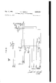
Figures 3, 4, 5 and 6, when arranged with 4 and 6 above and below 3, respectively/and 5 to the right of 3, illustrate in circuit diagram form, the
4 equipment required at one of the mobile stations.
Considering the drawings in greater detail, Figure 1 corresponds to Figures 1A, 1B and 1C of the previously indicated co-pending application; eX- cept that three outlet points and three inlet points to and from the radio link are provided, instead of only one. The equipment is otherwise identical to that previously described, and the same reference numbers have been retained, with the addition of suiix letters as required, to distinguish similar units of equipment associated with different points of access.
Thus, at the left in Figure l, a fixed subscriber station T is shown connected over the line 2 to a connector switch 22 for receiving calls, and to a finder switch l0 for initiating calls, it being understood that these switches are part of a group of similar switches serving a group of lines. A finder distributor and a line circuit, shown in the original drawing, have been omitted, in the interests of simplification. Associated with each line :finder |0 is a selector switch Il, forming therewith what is known in automatic telephony as a finder-selector link. The various switches employed are assumed to be two-motion stepping switches of the well known Strowger type, but almost any type of automatic switch in almost any type of automatic telephone system, would be equally satisfactory.
The selector has access to connector 22, by way of a 3-conductor trunk 2|, consisting of a pair of talking conductors and a test conductor,
not shown, and has access to other connectors, not shown, over similar trunks, for making local calls. For outgoing calls over the radio link, the selector also has access, over a group of 3- conductor trunks |2A, |2B and I2C, to the two- Way trunk repeaters 49A, 49B and 43C, each of which is identical with Figure 1B of the stated prior application. For incoming calls over the radio link, the repeaters 49 have access over the associated 3-wire trunks 23A, 20B and 20C, to the incoming selectors 24A, 24B and 24C, which also have access to the connector 22 and the other connectors, not shown.
In the outward side, the repeaters 49` are connected in turn to the corresponding auxiliary equipment units |19A, |19B and |19C, each of which is identical with Figure 1C of the prior single-channel system. Each repeater is joined to its associated auxiliary unit over four conductors including a pair of two-way talking conductors |1|A, B or C and |12A. B or C, a signal-out conductor |10A, B or C, and a signal-in conductor |13A, B or C. Means are provided in the repeaters for switching the talking conductors |1| and |12 from the trunks |2 to the trunks 20 as required, for sending ground pulses outward over the signal-out conductors |10, and for receiving incoming ground pulses over the signal-in conductors |13.
Each auxiliary equipment unit |19 is connected to a corresponding radio station control circuit 300A, B or C by four talking conductors, comprising a pair of outward talking conductors and |9|A, B or C, and a pair of inward talking conductors |84 and |95, A, B or C. In the auxiliary equipment units, these one-way talking pairs are connected, by means of a hybrid transformer, not shown, to the corresponding two-way talking pair |1||12. In the auxiliary equipment units also, the signal-out conductors |10 are connected, in simplex, to the corresponding outward talking pair 'ISU-IBI, while the signal-in conductors it are'm connected, in similar fashion, to the .corresponding inward tallingpair A19t-|95( In Figure 2, illustrating the radio control sta;-v
associated with the #2 and #3 channels, respec' tively. All of these circuits areide'ntical with one another, and are likewise identical with theradio` station control circuit of lthe' aforementioned prior application, Si. N. 55,627, led October 10, 1948, .as shown in Figures 2 and S'thereof, except ior the addition of sixrelays tol send out the momentary 3G00 cycle seizure tone on a call from the exchange, and tosend out the splash of carrier upon therelease ofia connection. A.This modication, as indicated, in the partial circuit di'agram shown for control circuit 300A, consists of two new relays 00ml and. BIUA which serveto put out the 3000 cycle seizure tone, and four new' relays 330A, 840A, 850A and 860A, which serve to put out the carriers on the release of a call. The seizure tone relays are operable from the existing contacts 20M. of the hold Vrelay 205A through a new pair of break ycontacts 855A .which have been added to the existing squelch relay 250A. The carrierV splash relays are operable from a new set of break- make contacts 822A and 823A which have been added to the existing transmitter control relay 323A. These latter relays are arranged to put out the #2 and #3 carriers for a brief interval at the end of each call, to re-tune all mobile stations, and also serve to. busy all three channels at the exchange end at the same time, to prevent interference. Otherwise, the new and the old radio station control circuits` are identical. For this reason, the upper part of Figure 2 herewith, shows only the outward and inward speech circuits connected to the transmitter diA and the receiver 228A, and the control station end of the signal-out and signal-in circuits, together with theoutward pulsing relays 209A, ZiiA', 210A and 215A, the remote control relay MGA, the squelch relay y250A, the inward pulsing relays 215A and 280A, the supervisory relay 'Edel/l, the transmitter control relay 320A, and the new relays 300A, SIDA, 830A, 840A, 850A and SEEEA. Some of the contacts of the old relays have been omitted in the interest of simplicity. The new elements are also marked Vwith Yspecial designation numbers in the 800 series to prevent possible conflict with previously assigned number designations.
Figure 3 illustrates a portion of the mobile unit control circuits, including the 3-channe1 radio receiver 302,V at theV upper left, a ratchetdriven, three-level, ten-point selector switch at the upper right, a tone detector and oscillator, in the upper center, and a number of relays. The receiver 302 is normally energized and ready to receive signals while the mobile equipment is in service. The relay 315, which is connected in Thus, control circuit 300AY with the plate circuit of one of the receiver tubes,such
output. oi?v the receiver is normally connected to the` transformer`303 andthehceto the input side of'thepulsetonedetectors comprising the vacuuin tubes 308 and 309 and their -associated net- Worksg'while the plate voltage vfor these tubes is controlled from the squelch relay'.
"Andrnpulse 'repeating circuit, comprising the relays, 37d, 313,'3'l3`and 383, and controlled from the tone detecten rep'eats'a'n impulse'to the selector `eachtime` the3000 and 2800 cycle impulse tones' are received in the correct sequence, and in the proper time relation. The selector switch ooniprising aniotor "magnet Vr3| l, a release magnet' l 2, and three wipers 'and associated contact banks 334', 335,336, 331, 338, 339, is' controlleddn turn irom'j the said impulse repeating circuit. AEach mobileunit isass'igned a diierent BLLCligitcall number, 'as {compared'to Z-digit numbers' forthe singlec'hann'el system,l and the selec'- torbanks' are' so wired thatfbly the mobile unit having thefbanliV contacts 'Wired to correspond with thefdigits 4di'alled,"'will'be signalled.` The banlr connections shown in' Figure 3 are such that the relay 390'Will be operated only if theV first digit-,received is"4',the'relay 395 will be operated only vvhen the 'rst two digits are 45, and the signal relay 300 will bev operated only in response to the digits 456W Relay 360 controls audible and visual signals which serve to notify the calledfmobile subscriber of theincoming call. Of thev remaining relays included in Figure 3, relay V330 is a re-searching relay which operates wheneverV an unmodulated carrier is received from the control jstation to cause the mobile unit to be tuned to .a different frequency; relay 340 is a seizure relay'controlledfrom the hookswitch, and which serves to put the mobile units carrier on the air "both on the answering and initiation or" calls; relay 350 isa tunenstart relay, which operates from the seizure relay, and helps to control the researching operation at the conclusion of a call; relay 380 is a hold relay which operates whenever a modulated carrier is received from the control station, to delayv the researching operation at the various mobile stations until the destination of the call has been indicated;` and rrelay 335 is a kick-off relay which operates from the selector switch 39'4 assoon as any digit is received which'does not agree with the assignedY call numberof the mobile station involved, `and vcauses .such station to be tuned to a new channel at once.
Figure Il illustrates another portion of the mobile unit control circuits, including the 3- channel radio transmitter 4t2 at the upper left, and a vibrator-rectiiier iisd at the upper right, for supplying plate voltage to the transmitter, as required. This vibrator set comprises a step-up ltransformer i233 and a rectifier tube 43S, and an associated'vibrator comprising an electro-magnet Atti, a weighted reed fidi, and the contacts 32, 33, (ist. rfhe lvibrator set '330 is put into operation under control of the hookswitch when the mobile subscriberremoves his handset to initiate or to answer a call. Thepower relay 46E) operates at the same time to connect up the transformer 008. The relay 45t is an adapter relay controlled from thedial 5m to convert the tone detector circuit comprising the tubes 308 and 30e and their networks intotone oscillator circuits for generating the 3000 and 2800 cycle tones required for pulsing from the mobile unit. The relays mit and 113tare lpulsing relays controlled from the dial impulse springs fOr Aapplying the ceiver to another channel, .The audiofrequency 75 Oscillator output totheradio transmitter input i in the required manner. The transformer 435. in the upper center of Figure 4, connects the radio transmitter input circuit also to the telephone transmitter of the handset 50| for the transmission of speech.
Figure shows the dash control apparatus, including a telephone handset 50|, an associated hookswitch 533, a telephone dial 5I0, a power switch 5I8, and a number of signal lamps. The power switch 5I8, which is normally closed as long as the mobile unit is in service, connects battery to the control circuits, fully energizes the radio receiver, and energizes the lament circuits of the radio transmitter. The power-on signal lamp 5I6 is illuminated as long as the switch 518 is closed. The incoming call" lamp Slt lights whenever the associated mobile station has been selected by a call from a fixed station, and the in use lamp 5I5 lights whenever the handset is removed from the hookswitch. The signal lamp 5 I'l will light in case the mobile subscriber attempts to initiate a call while beyond the range of the fixed control stations carrier.
In Figure 6 are shown a cam controlled out-ofrange and call-timer, and a cam controlled tuning apparatus for re-tuning the mobile unit's transmitter and receiver to a new channel as required. The out-of-range and calltimer, shown at the upper right, comprises a motor and gear reduction unit 635, a shaft 639 mounting three cams 540, 645 and 650, a magnetic clutch 635, and a slow-to-operate relay 643. In this timer, Lwhich is controlled from the hookswitch, the out-of-range cam 645 is arranged to take the mobile station off the air in case the control station carrier is not received back promptly following the initiation of a call by the mobile subscriber. The cams 640 and B50 which constitute the call timer, are arranged to interrupt all outward or inward calls after 5 minutes and to give a warning signal after 41/2 minutes, or after any other predetermined time, dependent upon the setting of the cams and the speed of the shaft.
The retuning apparatus shown in the lower part of Figure 6, consists of a motor and gear reduction unit 60D, a shaft 629 for said motor mounting four cams SIU, 620, 625 and 630, and a three-channel tuning device 690. The motor Stil is started by the local control circuits whenever re-tuning of the mobile radio units is necessary, the cams 620, 625 and 630, and their associated spring contacts, control the tuning magnets 666, BIIl and 680, and the tuning release magnets 655, 615 and 685, while the cam GID assures a complete revolution of the tuning cams, each time the motor 600 is started.
The general description of the system, and of the apparatus involved as shown on the drawings having been completed, a detailed description of the circuit operation will now be given, by tracing the extension of a call in each direction over the network, in order to facilitate the complete understanding of the invention. It will be understood, of course, that the embodiment of the invention shown and described is not the sole embodiment nor necessarily the preferred embodiment, and that various changes and modications, such for example, as the use of more or fewer channels, may be made, without going beyond the breadth and scope of the invention.
EXCHANGE SUBSCRIBER, CALL 'I'O MOBILE UNIT Seizure of a radio channel Let it be assumed that the subscriber T" at 8 the automatic exchange of Figure 1, desires to make a call to a mobile unit, such as the mobile unit 50i] shown in Figures 3, 4, 5 and 6. The subscriber T accordingly removes the handset from his telephone, which is assumed to be included in the circle T, to initiate the call in the usual manner. Responsive to removal of the handset at the calling telephone, an associated line circuit, not shown, at the exchange end of the subscriber line 2 is operated. This line circuit accordingly makes the line 2 busy to all of the connector switches such as the connector 22 having access thereto, and causes line 2 to be yseized by an idle line-lnder such as the nder ,I0 in the group of nders associated with this line. The nder then immediately switches the calling line through to the associated selector switch II, which returns dial tone and clears the line circuit from the calling line, in known manner.
Upon hearing the dial tone, the calling subscriber at the substation T now dials the first digit of the call number, to select the radio level. The selector I I is thereby operated to the desired level, and hunts automatically therein, in known manner, to find an idle trunk. Tn a 3-channel system such as illustrated, there would be three trunks on the radio level, and it will be assumed that trunk IZA representing channel #1, is connected to the ist position in the level, trunk I2B representing channel # 2 to the 2nd position in the level, and trunk I2C representing channel # 3 to the 3rd position.
If the rst channel is free, the repeater 49A will be idle, and will be so marked at the selector I I, over the test conductor of the trunk I2A. The selector I i will accordingly stop on the first contacts of the level, and extend the calling line to the repeater 49A. The repeater 49A, in response to such extension, grounds its test conductor to hold the link I-I I, and to mark itself as busy in the banks of the other selectors having access thereto. The repeater 9A at the same time extends the calling line to the talking conductors IlIA and I'i2A leading to the auxiliary equipment 119A, and thence to the control circuit 300A over the outward and inward talking pairs ISQA, IQIA and IMA, IA. The repeater 49A furthermore, grounds the signal-out conductor HSA, which ground passes over conductors IQUA, ISIA in parallel to the repeating coil 235A in the control circuit, and thence to the line relay 200A, which operates.
Line relay 203A, upon operating, as stated, over the outward simplex control circuity at its contacts ZSIA closes an obvious circuit to hold relay 205A, which has been made slow to release by the use of a copper sleeve over its core. Hold relay 205A operates, and at its contacts 205A grounds conductor Slim for operating the transmitter control relay 3255A. Relay 320A upon operating, at its contacts 822A closes a circuit for relay 830A. Relay 33M, which is made slow to release by means of a copper sleeve on the core, is also given an operate time delay of some 5 seconds by being connected in series with a self-heating resistor 835A made of a negative temperature coefcient resistance material. As the resistor heats, its resistance drops, and the current increases steadily until it reaches a value suflicient to operate the relay, the relation being such in the present instance, that the relay 830 wil1 operate after approximately 5 seconds, lock itself direct to contacts 822A, disconnect resistor 835A, and prepare a circuit for relay 840A. Relay 320A further, at itscontacts 32 IA applies plate voltage to the tone oscillators, not shown, and to radio transmitter 30m. The oscillators thereupon start operating, to generate the 3000 and 2800 cycle modulating tones, and the transmitter 30 IA, responsive to the application of plate voltage thereto, puts its carrier on the air.
Hold relay 305A also, at its contacts 201A energizes relays 300A and 8IOA in parallel as follows: ground at contacts 201A, contacts 355A, relay 003A, contacts IA, and relay 8IOA. The seizure tone cutoff relay 800A, being made slow to operate by the use of a long copper slug on the armature end of the core, does not operate immediately, but the seizure tone relay 8I0 does operate. Relay 8IOA thereupon at contacts 0IIA opens the normal oscillator load circuit through the right resistor 259A, and at contacts IZA connects the 3000 cycle oscillator output across the resistor rei51A, which is in series with the audio frequency input circuit of the transmitter 30 IA. The 3000 cycle tone from this oscillator, not shown, is thereby impressed upon the carrier of the transmitter 30I as a modulation thereof, in known manner. Cut-off relay 300A then operates, after a delay of some 100 milliseconds, and at contacts 802A locks itself operated to the ground at contacts 201A. Relay 300A also, at contacts 00IA, causes the release of relay BItA. Relay 3IOA restoring, removes the 3000 cycle modulation from the carrier, and restores the original circuit to resistor 259A. The energization or the high voltage circuits of the transmitter 33m also causes operation of the supervisory relay 235A through contacts 253A of the squelch relay, and relay 245A, by contacts, not shown, connects ground and battery to the secondary of the repeating coil 231A and so to the inward talking conductors I94A and IBSA for the operation of a relay not shown, in the auxiliary equipment unit H3A, which returns a second dial tone to the calling subscriber T, over the talking conductors VHA and I 12A, the outgoing trunk I2A and the line 2.
Responsive to transmission of the carrier of the iixed radio transmitter 30IA, all of the mobile station radio receivers that are tuned to this channel, which Will include all those not already occupied with a call, will respond to this signal. In the mobile unit 500 for example, assuming it to be free at this time, upon receipt of the carrier thereat, the souelch circuit, not shown, in the radio receiver 302, causes the energization of the squelch relay Relay 320 being made slightly slow to operate by means of a short circuited lower winding normally closed through break contacts 32E, operates after a delay of a few milliseconds. Relay 320 thereupon at its contacts 32| disconnects its lower winding and at its contacts 322 connects plate voltage from the receiver 302 to the tone detector tubes 308 and 309, by way of contacts 333, relays 313 and 310, conductors 423 .and i323, and contacts 453 and 45B. Squelch relay 323 also, at its contacts 323 grounds various points in the mobile station control circuits, at its contacts 325 opens the call initiating circuit from the hookswitch and conductor 525, and at contacts 324 prepares the call answering circuit, which, however, can be completed only at the called station, as will be seen. Contacts 323 also extend ground to relay 330, by way of contacts 30! and Relay 333 is provided with an opern y ate time delay of some 50 milliseconds, however',
by the use of a normally short circuited winding on the armature end of itsv coil, and does .not
10 operate immediately. This short circuit includes the contacts 345 and 389.
Responsive to transmission over -the carrier of the stated splash of 3000 cycle seizure tone, which appears at the antenna 302 just prior to the operation of the squelch relay 320, the radio receiver 302 causes an equivalent tone of this frequency to appear across its audio frequency output circuit, which is connected through contacts 342 to the primary of transformer 303. The 3000 cycle tone is thereby induced into the secondary of transformer 303 and thence to the tuned circuits 3| 3 and 3I9, over conductors 4I0 and 4I I, contacts 453 and 454, and conductors 4I8 and 4I9. The tuned circuit 3I3, comprising the condenser 303 and transformer 304 is tuned to select the incoming 3000 cycle tone and apply it to the grid of the associated tube 308. The tuned circuit 3I9, comprising the condenser 301 and transformer 305, is tuned for 2800 cycles and does not respond to the 3000 cycle tone.
The tubes 308 and 309 normally have their grids biased close to cut-off, so that when the 300.0 cycle voltage is caused to appear on the rid of the tube 308 by 4the tuned circuit 3I3, the tube conducts sufficiently for the operation of the impulse repeating relay 310, which is connected in its plate circuit over conductor 420, contacts 458, conductor 424, winding of relay 310, and resistance bank 321 to the tubes cathode. Relay 310 upon operating, at its contacts 312 completes a circuit to hold relay 380 as follows: ground through contacts 3i6, 323, 333, 349 and 312 to relay 380. Relay 380, which is made slightly slow to operate by means of a short copper slug over the armature end of its core operates after a brief delay, and at contacts 382 locks direct to the ground through contacts 349. Relay 380 also, at its contacts 38| opens the circuit to re-searching relay 330, before the latter has had time'to operate.
Meanwhile the closure of contacts 31I on the impulse repeating relay 310, has also caused operation of relay 316, from the same ground through contacts 343, over contacts 31| and 314. This in turn causes the operation of relay 383 from the same ground, through contacts 312 and 31S. Relay 383 at contacts 384 extends the same y ground to release magnet 3I2 which also opcrates. This is without effect, however, and upon removal of the 3000 cycle seizure tone, when relay 310 restores, relays 310 and 383, and release magnet 3I2 also restore, while relay 380 remains operated over its locking contacts 382.
Selecting mobile unit Assuming that the calling subscriber at the fixed substation T is calling the illustrated mobile unit 500, he will upon hearing the second dial tone, proceed to dial the remaining digits of the call number, in this case 456, as previously explained.
Responsive to the dialling of the first digit 4 the line loop to the repeater 49A is opened and re-closed four times, -thereby causing a line relay, not shown, in the repeater, to release and re-operate four times. This in turn opens and closes the outward simplex control `circuit over conductors I10A and conductors I 00A and I9IA to line relay 200A inthe control station, which relay also restores and re-operates four times. At each release of relay 200A, contacts 20IA thereof momentarily open thecircuit of hold relay 205A which is not aifected, however, due tobeing made slow torelease. At each release of relay 280A also, contacts 282A close acircuit to pulsing relay 2I8A by way of contacts 238A and 2I8A. Relay 2| 3A thereupon opera-tes, at contacts 2| 3A closes a holding circuit for itself, at contacts 2I4A prepares a circuit for pulsing relay 2I5A, and at contacts 2|2A connects the 3000 cycle modulation tone from contacts 8| IA to the resistor 251A and the input circuit of the transmitter 38|A, whereby it is again superimposed on the carrier, as a modulation thereof.
At each reoperation of vline relay 288A on the other hand, contacts 282A open the original operate circuit for relay 2 IIJA, now locked to contacts 281A, while contacts 23|A re-close the circuit of relay 285A, and connect ground to pulsing relay 2I5A over contacts 2I4A. Relay 2I5A thereupon operates, and at contacts EISA locks to ground at contacts 281A, through contacts 2|8A and 2I4A. Relay 2I5A also at contacts 2|9A opens the locking circuit to pulsing relay 2II'IA, and at contacts 2I1A connects the 2800 cycle modulation tone to the resistor 253A and the input of the transmitter 38| A, whereby it is likewise superimposed on 'the carrier as a second modulation thereof. Pulsing relay 2|3A, being made slightly slow to release by the use of a non-inductive shunting resistor, holds its armature for a brief interval following 'the open- .ing of its locking circuit, so that both tones are on the carrier for a short time. Relay 2|3A upon restoring, removes thev 3000 cycle tone, and at contacts Z I3A and 2 I4A` further opens its own locking circuit and Aopens the locking circuit of relay 2I5A. Relay 2|5A accordingly also restores after a .similar brief delay, to remove the 2800 cycle tone, and to re-prepare the operate circuit to relay 2|8A, in. readiness for the next impulse. The succeeding digits act in the same manner, the only difference being in the number of impulses.
In the mobile unit 588, as in the other mobile units not shown, the' first pulse of 3000 cycle tone is passed from the radio receiver 382 through transformer 383 as before to the detector tuned networks 3 I 3 and 3 I9, where vit is picked off by the network 3I3 and applied to the grid of tube 388. The tube 388 again conducts and operates its plate relay 318. Relay 318 upon operating, at its contacts 31| again operates pulsing relay 313 from the ground at contacts 3FG, through contacts 323, 333, 349, 31|, 314. Relay 318 also, at contacts 312 closes the operate -circuit to hold relay 380, but this has no effect at this time as relay 388 is now locked operated. Relay 316 upon operating, at its contacts 318 `prepares a circuit to the selector switch motor magnet 3| I, and at its contacts 319 passes the ground from contacts 312 to the release' relay 383. Relay 383 upon operating, at its contacts 385 opens the selector switch wiper circuit, andgat contacts 384 passes multiple -1 ground from contacts 312 and 382 to the selector switch release magnet 3I2, which also operates. The release magnet 3I2 upon operating engages a holding pawl with the driving ratchet, not shown, in order to hold the ratchet in place as it is advanced by the motor magnet 3| I.
The first pulse of 2800 cycle tone, which arrives at about .the mid-point of the rst dialled impulse, now appears `at the antenna 332 and is passed through the receiver 302 to the transformer 333. There, it is rpassed by induction to the detector tuned networks 3I3 and 3I3 over the conductors 4|8 and 4| I; contacts 453 and 333, and conductors 4 I8 and 4I 9. Since the network 3I3 is resonant at this frequency it causes. the 2800 CyCle 12 signal to beI applied tothe grid of the tube 309. The tube 389 thereupon is made conductive and operates the impulse repeating relay 313, which is connected in its lplate circuit, over conductor 42 I,
`contacts 453, conductor `423, winding of relay 313,
and resistor bank 321 to the tube's cathode.
Plate relay 313 upon operating, at its contacts 314 opens the circuit tov pulsing relay 318, which however, is made slow to release, by the use of a shunting non-inductive resistor and a condenser, and holds its armature for a brief interval. Plate relay 313 also at its contacts 315 passes ground from make contacts 31| to the stepping magnet SII, by way of contacts 318. Stepping magnet 3| I thereupon operates and advances the driving ratchet, not shown, and the associated wipers 334, 333 and 338 one step, thereby causing the wipers to engage the first contact in each level of the contact bank.
The plate relays 310 and 313 are both held operated for an interval somewhat exceeding the operate time of the stepping magnet 3| I, whose circuit is opened by the removal of the 3000 cycle tone. Upon removal of this tone, plate relay 318 restores, and at contacts 31| opens the circuit to magnet 3II which restores. Relay 310 also at contacts 312 removes one of the multiple grounds from release relay 383s'till held from contacts 382. Upon removal of the 2800 cycle tone shortly thereafter, plate relay 313 also restores, and further opens .the circuit to the stepping magnet 3| I. Pulsing relay 31,6,which restores at approximately the same time or shortly thereafter', now opens the circuit to the release relay 383, at contacts 313. Relay 383 is made slow to release, however, by the use of a long copper slug on the heel end of the core, and maintains its armature operated during the pulsing. The release magnet 3I2 is therefore also held operated, from the ground through contacts 382 on the hold relay and contacts 384 on the release relay.
Upon the dialling ofthe second digit the relays 310, 313, and 316 are causedto operate similarly, with release relay 383 and release magnet 3172 operating as before on the first impulse, and remaining operated until shortly after the last impulse of the series. The stepping magnet 3II is therefore operated and released five times instead of four, and advances the wipers quickly to the #5 contacts 'inthe bank. When, therefore,
`13 release relay 383 restores, shortly after the last impulse of the series, during the inter-digital pause, the quick-closing break contacts 385 thereon complete a circuit to transfer relay 395, from the ground at contacts 382, through contacts 385, 392 and 398, wiper 336, and contact in the bank level 33t'. Relay 395 accordingly operates and locks, and at contacts 397 and 398 transfers the Wiper circuit from wiper 336 to wiper 333. The switch then releases, due to the opening of contacts 384 of the release relay and the resulting restoration of the release magnet 3|2.
Upon the dialling of the nal digit 6, the action is again similar, and the stepping magnet 3 i 2 is accordingly operated and released six times, to advance the wipers to the #6 contacts in the bank. When now, release relay 383 restores as before, shortly after the last impulse, it closes a circuit to the signal relay' 366, from the ground at contacts 392, through contacts 335, 392, 391, wiper 338, and contact #6 in the bank level 339. Relay 339 operates over this circuit, and the selector switch then releases as before.
The signal relay 333 upon operating, at its contacts 35| locks itself operated direct to ground at contacts 323 of the squelch relay, at its contacts 365 prepares the answer circuit, which is thus made operative only at the called mobile station, at its contacts 3169 closes a circuit for lighting the incoming-call signal lamp 5M over conductor 529, and at contacts 365 and 333 completes an audible signal circuit. This latter circuit'which may originate in any convenient source of audible tone, and is here considered as a tap on the vibrator side of the radio receiver high Vol-tage rectiiier unit, not shown, passes over conductor 325, through contacts 349 and 333, conductor 323 to the input side of the output ampliiier circuit not shown, in the receiver 392, which ainplies the tone to a high level and impresses it on the receivers audio frequency output circuit, from where it is passed over conductor 329, contacts 366, and conduct-or 522, through the receiver of the handset 594 to ground. The handset receiver thereupon converts the tone into -a loud audible f signal easily heard by the called mobile subscriber.
Mobile subscriber answers The called mobile subscriber, responsive to the audible and visual signals received, answers the call by removing the handset 595 from the hookswitch 533. The hookswitch contacts 565 thereupon close a circuit to the in use lamp 545 from ground on conductor 528, through contacts 595 and lamp 5|5 to battery at the power switch 5|3. Contacts 565 at the sance time extend the saine ground over conductor 529 to the timer clutch 635. The lamp 5|5 accordingly lights, and clutch 336 operates and connects the cam shaft 939 to the timer motor 535. The hook switch contacts 534, which close at the same time, extend the ground from conductor 523 to the seizure relay 349, over conductor 526, contacts 365 and 32 4, conductor k633, contacts 652 and 3|6, and conductor 6|8 to relay 349. A branch or this circuit also extends from. contacts 335 over conductor 524 to contacts 65! and 646. At contacts 65|, this multiple ground is further extended to the timer motor 635, which thereupon starts driving the shaft 639 and the associated cams in a 1clockwise direction. Cam S45, shortly thereafter, opens contacts 646, which remove one of the shunts across the contacts 65| and 352.
The seizure relay 343 operates, and at its contacts 34| closes the start circuit to the high voltage vibrator 499, over conductor 498, from direct ground at conta-cts 3|6. Relay 349 also, at contacts 342 disconnects the audio frequency output circuit of the radio receiver 392 from the transformer 303, and at contacts 343 connects the said output circuit to the handset receiver, over conductor 522. Relay 34D also, at its contacts 344 dis connects plate voltage from the tone detector, at contacts 345 opens another point in the operate circuit for relay 339, at contacts 346 operates relay 350 which locks to ground at contacts 6|5 of the tuner, at its contacts 349 opens the locking -circuit of the relays 331i, 399 and 395 which restore, and at its contacts 349 opens the audible signal circuit.
Upon the grounding of the vibrator start conductor 498, from contacts 34|, power relay 496 is energized. This relay is made slow to operate, however, by means of a long copper slug on the heel end of its core, and does not operate its contacts for a period of some milliseconds. Meanwhile, the start ground on conductor 499 has also passed through contact 492 on the vibrator to the electromagnet 495 which attracts the reed 49|. The reed 49| thereupon closes contact 493 and opens contact 492. The opening of contact 492 opens the circuit to magnet 495, whereupon the weighted reed 49| is released and-swings back to close contacts 494 and re-close contacts 492. The magnet 495 is thereby re-energized and again attracts the reed 49|. This action continues as long as ground is held on the start conductor 499, with the swinging reed 49| alternately grounding the contacts 493 and 494.
Upon operation of the power relay 430, contacts 463 on this relay energize the transmitter of the handset 53| in series with the primary of the transformer 435 over the following circuit: negative battery through relay 460, contacts 463, choke coil 465, primary winding :o-fvtransformer 435, com ductor 512 to Figure 5, and the handset transmitter, to ground on conductor 528. Power relay 459 also, at its contacts 46| and 462 connects the primary windings of the step-up transformer 493 .to the contacts 493 and 494. Thenceforth, each time the weighted reed 49| closes the contact 493 it energizes the right-hand primary winding or transformer 493, and each time it grounds the contact 494 it energizes the left-hand Winding. High alternating voltages are thereby induced alternately in the secondary windings of the transformer 493, each half Wave being passed in turn through the rectifier tube 493, and appearing as a high pulsating positive voltage on the conductor 499 leading to the radio transmitter 402, where it is smoothed out by a suitable filter and applied to the plate circuits, not shown. Responsive to the application or" the high voltage to the mobile units radio transmitter 492, the latter, which is tuned to the #l channel, places its #l carrier on the air.
Radio receiver 226A at the radio control station, which is permanently tuned to the mobile units #l carrier, responds to this signal, and operates its squelchl relay 253A, over the conductors 229A. Relay 256A. thereupon, at its con tacts 25|A connects a'second ground to relay 329A, to maintain the high voltage to transmitter 30 IA and hold its carrier on the air independently of contacts 209A, which were closed as previously explained when the control circuit 363A was ilrst seized by the calling fixed subscriber T. Relay 259A also, at its contacts 253A releases supervisory relay 245A,which in turn at contacts not shown, removes thev previously applied ground andbattery from the inward talking conductors I94A and IBSA, thereby causing the release of the previously operated dial tone relay, not shown, in. the auxiliary equipment unit I'FBA. Relay 253A further, at contacts 855A opens the original operate circuit to the cut-oir relay 800A, and at contacts 234A completes the inward simplex control circuit extending from ground at contacts 354A, through contacts 282A and ZlSA on the inward pulsing relays, both windings of relay MzlA in parallel, conductors IMA and I95A in parallel, both windings in parallel of the dial tone relay, not shown, at the auxiliary equipment unit, and over the signal-in conductor H3A to a signal-in relay, not shown, in the repeater (59A. The dial tone relay and relay 249A whose windings are opposing when energized in parallel, do not operate in this circuit, but the signal-in relay, not shown, in repeater 49A does operate, and causes reversal of the battery feed to the calling line in the usual manner, for recording and/or supervisory purposes as required.
A complete two-way talking connection is now established between the calling subscriber at the xed substation T and the called subscriber at the mobile station 500. The outward talking circuit extends from the calling subset T over its line E, through the lnder-selector link il), I I, the trunk i2A, repeater 49A, conductors HIA and WEA, auxiliary equipment I9A, conductors IQA and IQIA, repeating coil 236A and lter 285A to the input terminals of the radio transmitter t'lA, whereby the outward speech frequencies are impressed upon the carrier thereof and transmitted to the radio receiver 302 in the mobileunit 550, where they are amplied and impressed across the output circuit of the receiver, and thence over the contacts 343 and conductor 522 to the telephone receiver in the handset SH. The inward talking circuit extends from a local circuit including the telephone transmitter in the handset 5cl, conductor 512, the primary of transformer and condenser 466, through the transformer A35 to the input terminals of the radio transmitter 432, whereby the inward speech frequencies are impressed upon the carrier thereof and transmitted to the radio receiver 228A at the. control station, where they are amplied and impressed across the output conductors 233A, from where they pass through the T network 238A, repeating coil 231A, conductors IMA and I95A, auxiliary equipment unit IIQA, conductors IIIA and IHA, repeater 49A, trunk IZA, link Ill, II, and over line 2 to the substation T.
Normal release If the calling xed subscriber T hangs up first, at the conclusion of the conversation, the replacement of the receiver or handset at the substation T opens the calling line loop to the repeater' 518A, thereby releasing the repeater line relay, not shown, which removes ground from the signal-out conductor I'IQA, but does not release the repeater. The line relay 230A at the control station also restores, and at contacts 20m opens the circuit to hold relay A. Relay lA being slow to release, remains operated for an instant however. During this time contacts 2512A close a circuit through contacts ZilBA and ZISA to pulsing relay 2IOA which operates. Relay zA thereupon at its contacts 252A puts the 300i) cycle modulating tone on the air for a brief interval. Relay 205A then restores, and at contacts 2cm and 205A opens the 'operate and locking circuits to relay 2IOA which restores, and removes the 3000 cycle tone from the carrier. Contacts 201A also open the locking circuit to relay EMA which restores, while contacts ESSA remove one of the grounds from relay 32E-A now held energized from contacts ZEiA on the squelch relay. At the called mobile station, the splash of 30530 cycle tone is without eiect due to the fact that the high vvoltage supply to the tone detector is now open at contacts 344. It is also without eect at the other mobile stations, since they are now tuned to another channel, as will be shown subsequently in a separate section on tuning.
When the called subscriber in the mobile unit S replaces the handset Ell-I, following release by the calling fixed subscriber, contacts ci the hookswitch open the circuit to the in use lamp SI5 and the timer clutch while contacts 584 open the circuit to the timer motor 635 and the seizure relay 34E. The lamp ESI is thereby extinguished, the clutch i536 disengaged, the motor 835 stopped, and the relay 3411i re leased. Upon release of the clutch S33, the restoring spring 63'! returns the shaft 233 and the associated cams 649, 645 and G59 to their normal illustrated position. Relay 345) upon restoring, at its contacts 3d I, opens the start lead [33 to the transmitter high voltage circuits, at its contacts .M2 and 343 disconnects the radio receiver output circuit from the handset receiver and re-connects it to the transformer 393, at its contacts re-connects plate voltage to the tone detector, at its contacts 35,5 operates relay 33t from ground through contacts 3m, 323, and 3M, at contacts 343 removes its ground from relay 3,53, and at contacts 341 starts the tuning motor by way of contacts 35d. Responsive to removal of ground from the vibrator start conductor 4&3, the vibrator stops and relay d68 restores, thereby deenergizing the handset transmitter and the high voltage circuit of the radio transmitter. The latter thereupon removes the mobile stati-ou carrier from the air. Re-searching relay 33D upon operating, at its contacts energizes the tuning device coils 66B', 615 and 685 over the following circuit: ground, contacts 3l6, 523, 332, conductor GES, contacts Si, conductor Q92, contacts 3I'I, conductor GDI, and contacts Ertl and 623. Since this station is already tuned to channel #1, this is without eect, and the motor alle makes one revolution and stops, the contacts l 5 thereof releasing relay 35u just alter the start of the rotation, and contacts E i 2 thereof assuring the completion of the rotationA Squelch relay 250A at the control station restores, in response to removal of the called mobile stations carrier. Squelch relay 250A thereupon, at its contacts 254A opens the inward simplex circuit to the signal-in relay, not shown, in the repeater 49A, which relay then restores, and releases the repeater, and the held link ill, II in the automatic exchange. Relay 250A also, at its contacts 855A re-prepares the operate circuit for cut-off relay 800A, at its contacts 25IA removes the last ground from the transmitter control relay 320A, and at its contacts 253A re-closes the circuit to supervisory relay 245A. This circuit is opened immediately, however, in the transmitter, due to removal of the high voltage, and is of no consequence at this time.
Relay 830A, which is made slow to release by the use of a a copper sleeve, holds its armature for a brief interval however, during which time a circuit is completed to relay 843A from ground through contacts 823A and 833A. Relay 838A accordingly operates, at contacts 84|A locks to ground at contacts 852A, at contacts 342A closes a multiple circuit to the slow to operate relays 85|)A and 330A, and at contact- s 833A, 844A and 845A grounds the inward simplex circuits in all three control circuits, thereby seizing all three repeaters 49A, B and C and making them busy. If any of these repeaters are already busy, this action will not affect them as their inward simplex is already grounded from the squelch relay of the associated control circuit.
It should be pointed out at this time that the relay 863A which puts the #2 and #3 carriers on the air momentarily, is made slow tooperate by the use of an armature end slug, and is provided with an operate delay interval of some 30 to 50 milliseconds. Relay 85D, on the other hand, which cuts off the stated splash of carrier, is provided with an operate time delay of approximately l/z second, by being connected in series with a self-heating resistor 854A made of a negative temperature coelicient resistance material. As the resistor heats, its resistance drops and the current increases. steadily until it reaches a value sufficient to operate the relay, the relations being such in this case that the relay operates in approximately 500 milliseconds. Any other form of timing arrangement to give the same delay would be equally satisfactory.
Meanwhile, responsive to the removal from the air of the carrier of the control station transmitter SUIA, squelch relay 320 at the called mobile station restores. Relay 320 thereupon, at its contacts 322 opens the high voltage supply circuit to the tone detectors, at its contacts 325 again prepares the call initiation circuit, and at its contacts 323 opens the locking circuit to the signal relay 330 which restores. Relay 360, upon restoring, at its contacts 355 removes its shunt from contacts 325, and at its contacts 35S extinguishes the incoming call lamp 4.
Meanwhile at the radio control station, relay 868A operates from contacts 842A, after its brief delay period of some 30 milliseconds, and at its contacts 862A locks to contacts 85| A of the timer relay 858A. Relay 360A further, at its contacts 363A and 854A, operates the transmitter control relays 325B and 320C, in the control circuits 353B and 333C. Relays 320B and 320C thereupon connect up the high voltage circuits for the radio transmitters 3|l|B and 38|C which promptly put their carriers on the air. Relays 325B and 320C also close the circuit of the associated relays 830B and 833C, not shown, but the latter relays do not operate, as their circuits are closed for only 1A? second, instead of the required 5 seconds.
The calling mobile station is not affected by the carriers of the 2nd and 3rd channels put out by the transmitters 3MB and 30|C, since it is still tuned to the lst channel. The remaining idle mobile stations which may be standing by on either the 2nd or the 3rd channel, depending on circumstances, are affected and operate their squelch relays 32E), and their re-searching relays 333. Relay 330 in said idle mobile stations, thereupon, at its contacts 33|, locks to contacts 323, and at its contacts 332 closes a multiple circuit to motor 600 and the tuner magnets 660, 615, 685, as follows: ground, contacts 3|6, 323, 332, conductor 605, contacts 6|3, 6||, conductor 608,
At the radio control station, relay 850A operates after 1/2 second and at contacts 85|A and 853A opens the locking and operate circuits forrelay 350A, and at contacts 352A opens the locking circuit for relay 333A. The latter relay is made slightly slow to release, by the use of a heel-end slug, and holds its armature for a momen-t, but relay 830A restores quickly, and releases -the transmitter control relays 320B and 320C. The latter relays accordingly remove their carriers from the air, shortly after the start oi the rotation of the tuning motors at the mobile stations. Relay 845A then restores, releasing relay 853A, and at contacts 843A, 844A and 845A 'unbusies the repeaters 43 at the automatic exchange. At the mobile stations, the cam BIB at the completion of its rotation, again closes its contacts SI5 to re-prepare the circuit to relay 340, and the system is again ready to initiate calls, in either direction.
If the called mobile subscriber hangs up rst, on an outward call, the release operation is only slightly diierent. Upon replacement of the handset on the hookswitch a-t the called mobile station, the ho-okswitch contacts 534 and 505 cause the release of relay 36.13 and, the call timer, and the darkening of the lamps 5|5 and 5M as before. Relay 343 upon restoring, again takes the mobile stations carrier oiT the air, and operates relay 33|). Relay 33|! thereupon again locks to the squelch relay, and at contacts 332 energizes the'tuner coils 533, 675 and 685 as before, and starts the motor Sill?. The tuner then makes one revolution as before and stop-s, leaving the station tuned to the lst channel. If the calling station does not release at once however, the station will be tuned to a different channel, as will be shown subsequently.
Squelch relay 250A at the control station restores, responsive to removal of the called mobile stations carrier. Relay 253A thereupon at its contacts 25|A removes one of the grounds from relay 323A, which remains energized, however, from contacts 236A. Relay 253A also, at conta-cts 253A closes the circuit of supervisory relay 245A, at contacts 253A opens the inward simplex circuit, and at contacts 855A re-closes the operate circuit to cutoi relay 833A now locked to ground at contacts MWA. Responsive to the removal of ground from the inward simplex at contacts 254A, the signal-in relay, not shown, in the repeater 39A restores, and again reverses the talking battery to the calling line. Supervisory relay MEA operates responsive -to the closure of its circuit, and at contacts, not shown, again connects ground and battery to the inward talking circuit, thereby re-operating the dial tone relay, not shown, in the auxiliary circuit 13A to give a disconnect signal to the calling subscriber.
n When the calling subscriber T hangs up, the line relay, not shown, in the repeater 49A restores, releasing the repeater, and the link I0, Il at the automatic exchange. Ground is removed from the signal-out conductor |`|A and the outward simplex circuit, thereby causing the release of the line relay 200A at the control station. Relay 200A upon restoring, at contacts 20M-l opens the circuit to the slow to release hold relay 205A, and at contacts 202A again operates pulsing relay 2|0A through contacts 208A and 2|9A. Relay 2|0A thereupon at contacts 2|2A again puts the 3000 cycle seizure tone on the carrier of transmitter 30|A. This seizure tone is picked up by the radio receiver 3D2 at the called mobile station, but is without effect at the other mobile stations, which are now, as previously stated, tuned to another channel. At the called mobile station 500, however, where the tone detector is again in operative condition due to the release of relay 340, the 3000 cycle tone is passed from the radio receiver 302 to the detector, and causes the operation of plate relay 310. This relay is now ineffective, however, since there is no ground `available at the contacts 3l| and 372, due to the now open contacts 333 on the operated re-searching relay 330. I-f the called station is now tuned to another channel, due to the calling subscriber not hanging up promptly, the 3000 cycle tone will of course be completely ineffective.
Upon the eventual release of hold relay 205A contacts 201A and 200A thereof open the circuits of relays 2 |0A and 800A and both of these relays restore. At the same time contacts 205A on the hold relay remove the last ground from transmitter control relay 325A, which restores. Relay 320A thereupon, at -contacts 32|A removes the high voltage from the tone oscillator, not shown, and the transmitter 30|A as before, at contacts 822A opens the circuit to relay 330A which holds for an instant, and at contacts 323A operates relay 840A. Relay 840A then locks, energizes relays 850A and 860A in parallel, and busies the repeaters 49A, B and C, exactly as prev-iously described.
Meanwhile the transmitter 30|A, responsive to disconnection of its plate voltage by relay 320A removes its carrier from the air. At the called mobile station, squelch relay 320 thereupon restores, and at its contacts 323 opens the locking circuit for relays 330 and 360 which also restore. If the calling station failed to disconnect at once, lhowever, the station will be tuned to a new channel, the relays 320, 330 and 360 will all be already normal, and the removal of the carrier of the transmitter 30|A will be in itself completely without effect, except as to subsequent tuning operations.
At the radio control station, relay 860A operates as before, shortly after the closure of its circuit at conacts 842A, and puts the #2 and #3 carriers on the air exactly as before, by operating the transmitter control relays 320B and 320C. Approximately 1/2 second later, relay 350A operates, and deenergizes relays 860A and 840A. Relay 860A restores quickly, and takes the #2 and #3 carriers olf the air, and shortly thereafter relay 840A restores and unbusies the repeaters 49A, B and C. The control station is now again lat normal, and the idle mobile stations are retuned in response to the aforementioned splash of carrier, as previously described.
It will be understood, o course, that a simple timer could be added to the repeaters 49 to release said repeaters, and the connected switches at the exchange after a certain interval, in order to prevent an exchange subscriber from holding a radio channel busy by failing to hang up after an outward call. Such schemes are well known in automatic telephony, especially for small exchanges, and need not be described here.
MOBILE UNIT CALL TO EXCHANGE SUBSCRIBER Seizure of a radio channel Let it now be assumed that the mobile subscriber at the mobile station 500 desires to make a call to the xed substation T in the automatic exchange. To initiate the call, the subscriber at the mobile station merely removes his handset 50| from the hookswitch 503, in the usual way. Responsive to removal of the handset, hookswitch contacts 505 light the in use lamp SI5, and operate the timer clutch 635 over conductor 529. At the same time, hookswitch contacts 504 close a circuit to the seizure relay 340, through back contacts of the squelch relay, as follows: ground, contacts 504, conductor 526, contacts 325, conductor 624, contacts 646 and 652 on the timer, contacts 6 I 6 on the tuner and conductor GIB to relay 340. A branch of this circuit also extends from conductor 624 by way of contacts to the timer motor 635, which starts driving the shaft 639 and its cams to time the call.
Seizure relay 340 operates, after a very brief delay, due to its being made slightly slow to opverate, and at contacts 34| passes ground from contacts 3|6 to the high voltage start conductor 408 as before. Relay 340 also, at its contacts 342 and 353 switches the output circuit of the receiver 302 from the detector circuit to the handset receiver circuit, at its contacts 344 disconnects plate voltage from the detector circuit, at contacts 345 opens the circuit to the re-searching relay 330, at contacts 346 closes a circuit to the tuner start relay 350, at its contacts 348 prepares a dial grounding circuit, at contacts 345 opens a point in the ground feed to the register circuit, at contacts 349 closes a self holding circuit, and at contacts 349 disconnects the hum signal on conductor 326 from contacts 36'! and conductor 522 leading to the handset receiver.
The tuner start relay 350 operates, from contacts 346, and at contacts 355 locks to contacts 6|5 of the tuning apparatus over conductor 6|'|. At the same time, the ground on conductor 408 from contacts 34| operates the vibrator 490 and the power relay 460, the latter being made slow to operate, to permit the vibrator to start before being connected to the transformer 598. The transmitter 402, in .response to the application of high voltage thereto, places its carrier on the air to seize the control station. For convenience of explanation, it will be again assumed that all channels are free, and that the transmitter 402 and the receiver 302 are tuned to their respective #l channel frequency. At the control station therefore, this #l carrier is picked up by the radio receiver 228A in the control circuit 300A, and causes the operation of the squelch relay 250A associated therewith. Squelch relay 250A upon operating, at its contacts 855A opens the operate circuit to the seizure tone relay 8|0A to prevent its operation, at contacts 254A closes the signal-in circuit, at contacts 253A opens the operate circuit to the supervisory relay 245A to prevent its operation, and at contacts 25|A grounds conductor 3|0A leading to transmitter control relay 320A. Relay 320A operates and applies the high voltage to transmitter 30|A, which immediately, in response thereto, places its carrier on 21 the air. Relay 32M also, at its contacts 822A energizes relay 333A, which operates some seconds later, as previously described, in series with the negative temperature coefficient resistor The return carrier from transmitter 33M is picked by the radio receiver 332 at all idle mobile stations, and operates the squelch relays thereat, thereby operating the associated researching relay from ground through contacts corresponding to 3&5, 323, 38l and 345. These stations are thereby immediately tuned to a new channel, in a manner to be described in detail under a separate heading. In the illustrated calling mobile unit 533 however, relay 33d is prevented from operating by the open contacts 345. At this station, therefore, the squelch relay 32@ upon operating, at its contacts 325 opens the original operate circuit for the seizure relay 34d, and at its contacts 324 closes a holding circuit for relay 34d which may be traced as follows: ground from the hookswitch on conductor 5%, through contacts 349 and 32d, conductor w3, contacts 352 and tit, and conductor 518 to relay 343. lt may be seen that this ground shunts contacts @t5 which are associated with the out-oirange timer, and renders them ineffective. The operation of this timer will be described under a separate heading. The squelch relay further at its contacts 323' removes ground from conductor titl leading to the out-of-range lamp circuit, at contacts 323 grounds the dial shunt springs 5l3 by way of contacts 333 and 343 and conductor 52E, and at contacts 322 connects the high voltage to conductor 4t@ leading to springs of the transfer relay 45t.
Meanwhile, at the control station, the grounding of the inward simplex circuit at contacts 2523A of the squelch relay 25d causes the operation of the signal-in relay, not shown, in the repeater MA, over contacts 232A and 353A, relay MBA, conductors lblA and 495A, auxiliary unit i'i, and the signal-in conductor H3A. The repeater 49A is thereby seized and in turn seizes an associated incoming selector 24A over the associated incoming trunk 23A, and marks itself busy at the banks of all local selectors such as il having access thereto, in known manner. The incoming selector thereupon connects dial tone in normal manner to the trunk 23A and this tone is passed back to the calling mobile subscriber over the outward side of the now extended speech circuits, including the two-Way talking conductors il' IA, l'lZA, the outward talking conductors lSdA, lQlA, the repeating coil EBiBA, radio transmitter 36M, radio receiver 332, contacts 343, conductor 522, and the telephone receiver in the handset tl.
Selecting exchange subscriber Upon hearing the dial tone from selector EtA, the calling mobile subscriber operates the telephone dial 5i@ in normal manner, to dial the digits composing the call number of the xed subscriber T through the switches of the automatic exchange. As soon as the dial 5 i S is moved from its normal position, an oit-normal cam, not shown, closes the shunt springs 5i@ which remain closed until the dial has again returned to its normal position. Closure of these contacts causes the operation of transfer relay 45d, from the ground at contacts 3 l l5, over contacts 323, 333
and 343, conductor 52S, shunt springs 5i3, and conductor 5l3 to relay 45t.v
When the calling mobile subscriber releases the dial to hend the first digit of the call number, it rotates back to its normal position, and the cam 5H during this rotation closes and opens the pulsing contacts 5|2 a number of times dependent on the value of the digit dialled. Upon each closure of contacts 5l2 pulsing relay 448 operates, from the ground on conductor 52|, through springs 543 and 5l2 and conductor 574 to relay ddd. At each such operation, relay 440 at its contacts Lidl closes a circuit to pulsing relay 43d, at its contacts 443 removes a short circuit from resistor 434 in the input circuit to the radio transmitter, and at its contacts 442 connects the left winding of the transformer 334 across the same resistor 434. The 3000 cycle output of the oscillator tube 368 is thereby impressed upon the input circuit of the radio transmitter 492 over conductors lli 5 and 4 I 6, contacts 442 and conductor 43?, and resistor 434, and is emitted by the transmitter 4t2 as a modulation of its carrier. Pulsing relay 433 also operates, after a short delay due to being made sluggish by the use of a shunting non-inductive resistor. Relay 430 thereupon at its contacts 432 removes a short circuit from resistor 433 in the transmitter input circuit, and at its contacts 43! connects the left Winding of transformer 3R35 across the same resistor. The 28d@ cycle output of the oscillator tube 369 is thereby impressed upon the input circuit of the radio transmitter 4t2 over conductors 4I4 and s55, contacts 653i and conductor 433, and resistor 333, and is emitted by the transmitter as a second modulation of the carrier. During each succeeding open period of the pulsing contacts 5l 2 relays 44S and 433 restore, and remove the 36B!! and et cycle modulating tones from the carrier. Relay 45E] restores when the dial gets back to the normal position.
These impulses of 3000 and 2800 cycle tone are picked up by the radio receiver 22A at the control station, and are passed thereby to a tone detector, not shown, over conductors 233A. The tone detector, in response thereto, operates the inward pulsing relays 215A and 280A once for each time the two tones are receivedsin the proper sequence and in the proper time relationship. Relays 275A and 286A accordingly open and reclose their contacts 218A and 282A in unison with the dial pulses, and repeat the impulses over the signal-in circuit comprising conductors 594A, 125A and H3A to the signal-in relay, not shown, in the repeater 49A. The signal-in relay in turn, repeates the impulses to the incoming selector 24A. The incoming selector 24A operates in response to these impulses to select the group of connectors having access to the wanted subscriber station T, and then hunts automatically to iind an idle connector in that group, such as the connector .22. The selector 24A thereupon switches the connection ahead to the seized connector.
The second and kthird digits are transmitted in like manner, andare passed through the selector 26A to the connector 22, which in response thereto extends the connection to the subscriber line 2. If the called line is busy, the connector 22 will pass back busy tone to the selector 2dr/l and the repeater 49A in the usual manner, and this busy tone will be passed back to the calling mobile subscriber by the radio transmitter 39 lA in the same manner as the dial tone trom the selector 24A, as previously described. Assuming that the called station is idle however, the connector marks this line as busy to the other connectors having access thereto, and connects ringing current to the called line to signal thecalled subscriber. At the same time, ring-back tone is passed back to the repeater 49A, and is passed back to the calling mobile subscriber by the radio transmitter SMA.
Exchange subscriber answers When the called subscriber T at the automatic exchange answers, the connector 22 switches through to complete the connection and cut ofi the ringing current in known manner. The connector 22 also reverses its battery loop back to the repeater in accordance with standard automatic telephone practice. Responsive to this reversal, an answer relay, not shown, in the repeater 49A is operated to ground the signal-out conductor HDA. This ground is thereby extended over the outward simplex to line relay ZiA at the control station which operates. Relay EMA in turn, operates hold relay 265A which, at its contacts 266A connects an additional ground to the power relay 320A to maintain the transmitter high voltage circuits, not shown. Relay BIBA does not operate at this time, due to the open contacts 355A on the squelch relay.
The connection is now completed and a regular two-way conversation may proceed `iust as for a call between two xed subscribers. The talking circuit for the mobile subscriber is now from the transmitter of the handset 50|, over conductor 5'12, transformer 35, radio transmitter 4t2, radio receiver 228A, conductors 233A, the T network 238A, repeating coil 231A, conductors IMA and WEA, auxiliary unit HSA, conductors IHA and IZA, repeater 29A, trunk 20A, selector MA and connector 22 to the telephone receiver not shown. at the called substation T. IThe talking circuit for the called subscriber is from the telephone transmitter not shown, at the called substation T, through the connector 22, the selector 24A, trunk 26A, repeater 49A, conductors VHA and il2A, auxiliary unit IQA, conductors HOA and ISIA, repeating coil 235A, lter 285A, radio transmitter 301A, radio receiver 322, contacts 343, and conductor 522 to the receiver of the handset 50|.
Talking batteryfor the called station is furnished from the connector 22, while talking battery for the mobile subscriber is from battery through power relay fitti through contacts 463, choke coil 465, transformer 6.35, conductor 5'i2 and the handset transmitter, to ground on conductor 528. The speech circuit for the handset transmitter is over the same circuit, but excluding the choke 265 and the relay litt, and including the condenser 455 in their place.
Normal release lf the calling mobile subscriber hangs up first, on such a call, the connection will be released at once. The replacement of the handset 5&1 at the calling mobile station opens the contacts 524 and 565 of the hookswitch, in the usual manner. Contacts 5M thereupon extinguish the in use" lamp 5w, and release the timer clutch 536, While contacts E05 open the circuits of the timer motor 35 and the seizure relay IME-0. Upon release of the clutch 635, the timer shaft 633 and its associated cams are restored to the illustrated normal position, by spring 53T. Relay 34D also restores and at its contacts 3M opens the start circuit to the high voltage vibrator 696. Relay 34W also, at contacts M2 and 3de re-connects the radio receiver output circuit to transformer 393, at contacts 3&5 re-connects plate voltage to the detector circuit, at contacts 3135 .closes a circuit to researching relay 33@ from ground through contacts 316, 323, 38E and Sf, at contacts 346 removes its ground from the locked up timer start relay 3252, contacts Bf'z' closes a circuit to motor 600 through contacvs 3512, and at contacts 3G19' opens another point in its own operate circuit, now open at contacts 325.
Ete-searching relay i operates, and at its contacts locks to ground at contacts 323. Relay 35e also, at its contacts 332 connects ground from contacts 323 to conductor Silo, and thence by way or contacts 6I3, conductor 602, and contacts 3H to the tuning lead 60E, thereby re-energizing the coils 666, 65 and 685 of the tuning device. This is without effect, and the armatures Eisi, 6H and 53| remain in the positions shown. The motor Gil@ also starts, responsive. to the closure of its circuit and drives the tuning cams one revolution. Cam GID operates its sprmgs shortly thereafter, whereupon springs till connect ground from contacts 323 to the tuning .conductors S and 662, springs SI5 open the locking circuit `to relay 350 which restores, and springs 66,2 prepare an alternative circuit to motor 6to over contacts 353, which is completed as soon as relay 352 restores, to assure the completion of the rotation.
Meanwhile, responsive to the removal of ground from conductor wil by contacts 34| of the seizure relay, power relay [46u restores, and the high voltage vibrator of Figure 4 stops operating. Relay fat thereupon de-energizes the handset transmitter and the high voltage circuits to the radio transmitter 292, which responds quickly and removes the #l mobile carrier from the air.
Responsive to the removal of this carrier squelch relay 256A at the control station restores Etelay 259A thereupon, at its contacts 253A recioses the circuit to supervisory relay 245A briefiy at. contacts 25|A removes its ground from trans: mitter control relay 320A which remains operated,.at contacts 254A opens the inward simplex circuit to the repeater 49A, and at contacts 855A re-closes the circuit to the seizure tone relays 809A and 810A, from the ground at contacts 201A.
Relay 8IOA operates immediately and at its contacts 8I2A places the 3000 cycle tone on the carrier of transmitter 301A. At the mobile station 500, this causes operation of plate relay 370 but this is without eiTect, as the ground circuit to its contacts 3H and 312 is now open at contacts 333 of the now operated re-searching relay 330. At the other mobile stations, the seizure tone, being on the #l outgoing channel, is entirely without effect, as these stations are now tuned to a diierent channel. Relay 800A also operates from contacts 855A after a delay of some 100 milliseconds due to its being made slow to operate, locks direct to contacts 201A, and releases relay 8l0A to remove the seizure tone from the carrier.
'Ihe signal-in relay, not shown, in the repeater 59A restores, upon the opening of its circuit at contacts 254A of the squelch relay 250A, and releases the repeater and the held switches 24A and 22 in the automatic exchange. The repeater 49A thereupon removes groundfrom the signalout conductor IlllA, shortly after the release of lthe squelch relay. Line relay 200A at the control station accordingly restores, and at contacts 201A opens the circuit of the hold relay 235A. Relay 205A being made slow to release remains operated for a brief interval, however. During this interval pulsing relay 2lllA operates over contacts 202A, 208A and 2|9A. Relay 2l0A upon operating, at its contacts 212A again puts the 3000 cycle seizure tone on the carrier, with the same eiects stated in the previous paragraph. Relay 205A then restores and releases relay 240A and the seizure tone relays 800A or SIGA, whichever is operated at this time. Relay 205A also at its contacts 206A removes the iinal ground from relai7 320A.
The transmitter control relay 32BA now restores, and at its contacts 321A removes the high voltage from transmitter 30IA. Relay 320A also at contacts 822A opens the circuit to relay 339A, which being slow to release remains operated for an instant. During this time a circuit is closed briey through contacts 823A and 833A to relay 845A which operates. Relay 840A therefore, at contacts 8M A locks to the timing relay 350A, at contacts 8l2A energizes the timing relay 850A and the slow to operate relay 860A in parallel, and at contacts 843A, 846A and 845A grounds all of the inward-simplex circuits, thereby seizing the repeaters 49A, B and C as for an inward call, and making them busy to all selectors in the automatic exchange having access thereto.
Responsive to the removal from the air of the carrier of the control station transmitter BMA, squelch relay 320 at the calling mobile station restores. Relay 32B thereupon, at its contacts 322 removes the high voltage from the tone detector circuits, and at its contacts 323 removes tuning ground from conductors 605, 606., 602 and 50i, and at the same time opens the operate and locking circuits to the re-searching relay 330, which restores. At this time the shaft E29 of the tuner will have made less than 1A; revolution, and since the cams 25 and E330 do not close their contacts until after 1/3 and 2/3 revolutions, respectively, the original tuning remains effective. On the completion of the rotation therefore, the motor G will stop, due to the opening of contacts M2, contacts Eil will again prepare the circuit to relay 340, and the station will be again i operates from contacts 842A after a delay of some fil 25 30 to 50 milliseconds, due to its armature end slug, at contacts 862A locks to contacts |A on the timer relay 850A, and at contacts 863A and 864A operates the transmitter control relays 320B and 320C to put the #2 and #3 xed carriers on the air, from radio transmitters 3MB and 30|C. Relays 320B and 320C also complete a circuit to the associated relays 830B and 830C, not shown, but these relays do not operate, as their circuits do not remain closed for the required 5 seconds.
The calling mobile station is not aiected by the fixed carriers # 2 and #3 now emitted by the radio transmitters 30IB and 301C since it is still tuned to the 1st channel. The remaining idle mobile stations however, which will be standing by on one of the other channels, will operate their squelch relays 320 and their re-searching relays 330. The relays 330 thereupon lock and at their contacts 332 operate the motor 600 from ground, contacts 3l6, 323, 332, conductor 605, contacts 6|3, 6H, conductor 608, contacts 353 and conductor 609 to motor i500. A branch of this circuit also extends from contacts GIS over conductor 602, contacts 3H, conductor 60|, and contacts 62|, 622 and B23 to the tuning magnet 660 and the tuning release magnets 675 and 585. The radio transmitters and receivers at these stations are thereby re-tuned to the 1st channel, and the shaft 629 makes one revolution and stops, in the manner previously described. The squelch relays 320 at these stations restore immediately, as soon as they are re-tuned to the 1st channel, and release the re-searching relay 330.
At the radio control station, the timing ,relay 850A operates, after 1/2 second, and at contacts 85|A and 853A opens the locking and operate circuits for relay 860A, and at contacts 852A opens the locking circuit for relay 840A. Relay 840A being made slightly slow to release holds its armature briefly, but relay 860 restores at once, and releases relays 320B and 320C The latter relays then open the high voltage circuits and the transmitters 30 IB and 30IC remove their carriers from the air. Relay 840A restores shortly thereafter, and at its contacts 842A releases relay 850A. Relay 840A also at contacts 843A, 844A and 845A opens the inward simplex circuits to free the repeaters 49A, 49B and 49C. The system is thereupon again at normal, and ready to initiate calls in either direction.
Should the called subscriber at the xed substation T at the exchange end hang up first, on such a call, the connector 22, responsive to interruption of the called line loop will again reverse `the polarity of the trunk 2BA in known manner. This causes the repeater 49A to partly release, and to remove ground from the repeater end of the signal-out conductor HUA. This causes the release of the line relay 200A at the control station. Relay 200A upon restoring at its contacts 201A opens the circuit to hold relay 205A which holds its arma-ture briey, as before. During this interval pulsing relay ZlilA operates from contacts 202A, 2ll8A and 2I9A, and at its contacts 2 l2A puts the 3000 cycle seizure tone on the carrier briey. At the calling mobile station this is without effect, as the tone detector thereat is now disabled, at contacts 344 on the operated seizure relay 340. It is also without effect at the other mobile stations, as their radio receivers are now tuned to a different channel. Hold relay 205A restores shortly thereafter and releases relay 2l0A. Relay 205A also, at itscontacts 206A-removes its ground from re1ay320A, which remains 27 Operated, however, from ground at contacts 25|A of the still Operated squelch relay 2553A.
When now, the calling mobile subscriber hangs` up, seizure relay 3,40 restores as before, and at contacts 34| again opens the circuit for power relay 463 and the high voltage Vibrator. Relay 340 also at contacts 345 operates the researching relay 330 over contacts 3|6, 323, 33|, and 345, and at contacts 341 closes a circuit to motor 60D, via contacts 354 and conductor 309.
Meanwhile, power relay- 450 has released, upon the opening of its circuitl at contacts 34| of the seizure relay 34B, and has removed plate Voltage from the transmitter 132, which thereupon removes i-ts carrier from the air. Squelch relay 250A at the control station thereupon restores, and at contactsl 253A removes ground from the inward simplex. This completely releases the repeater 49A and the switches 23A and 22 at the automatic exchange. Relay 250A also, at its contacts 2,5iA removes the last ground from relay 320A which restores. Relay 3211A thereupon at contacts 32|A removes the high voltage from transmitter 30|A to take its carrier off the air, at contacts 822A opens the circuit to the slow release relay 830A and at contacts 823A operates relay 840A. Relay 840A then locks, energizes timing relays 853A and 860A, and busies the repeaters 49A, 159B and 49C, exactly as before. Relay 860A then operates to put the #2 and #3 carriers on the air, and shortly thereafter, relay 850A operates. Relay 860A then restores, to removethe carriers # 2 and #3, and relay 840A restores shortly thereafter to release the repeaters. The calling mobile station is unaffected by these carriers, but the other mobile stations respond to one or the other and are thereby re-tuned as necessary.
MOBILE STATION TUNING General The automatic tuner provided ateach mobile station, consists essentially, as previously indicated, of a 3-channel tuning device 688, controlled from three tuning cams 620, 62.5 and 633 arranged to be driven one revolution by an asso ciatedmgtor 630,` each time re-tuning is required. A ith caml Gillis also provided for miscellaneous control functions. The motor is arranged to drive the shaft 629 in a clockwise direction at a vspeed to provide a complete rotation of the cams in 2 seconds. The motor control cam GIU operates its contacts almost immediately after the start of the rotation, and restores them to the position shown only at the conclusion of the rotation. The channel #l cam SZiiopens its contacts shortly after the start of the rotation, and recloses them shortly before the conclusion of the rotation. The channel # 2 cam 625 closes its contacts brieiiy after 1/3A of a revolution, or after an elapsed rotation time of some 666 milliseconds. The channel # 3 cam 63|)V closes its contacts briefly after of a revolution or after an elapsed 28 rotation time of some 1333 milliseconds. If ground is. found onv the tuning conductor 60| at the time any of the tuning cams have theirv contacts closed, the mobile stations radio receiver and transmitter will be tuned to the corresponding channel.
The tuning device 690 consists basically in 3 pairs of electromagnets, one pair for each channel, for controlling the tuning armatures 66|, 61| and 68|. These armatures, which are arranged to remain in their last operated position when the coils are deenergized, control separate tuning networks, in the radio receiver 362 and the radio transmitter 462, in the general manner indicated at the lower right in Figure 6 of the drawings. Since such arrangements are well known, they will not be described further, except to say that when any armature is .pulled up to the left by its associated tuning relay er electromagnet such as 533, 67B or 833, it closes an associated set of contacts such as ithe set including contacts B62 and 653, to tune the transmitter and' receiver to the corresponding channel, while when such armature is pulled up to the right by the associated tuning release coil such as 665, 515 or 685, the associa-ted contact set is opened, to disconnect the corresponding portion of the tuning network.
Also, the circuit arrangements are such that when any tuning coil is energized, from the corresponding tuning cam, the tuning release coils for the other two channels are energized at the same time. Thus when the tuning cams are in the normal position, as shown in the drawing, a ground placed on conductor 69| will pass through the closed contacts of cam 623, and tune the mobile station receiver and transmitter to the #l channel, if they are not already on this channel, by energizing the tuning coil 653 and the release coils 675 and 635 simultaneously. Under these conditions, the lett set of tuning contacts including contacts 832 and 533 will be closed, and the other contact sets will be open. Similarly, a gro-und on conductor 60| when cam G25 has its contacts closed, will tune the station to the #2 channel by energizing the tuning coil 'l and the rele- ase coils 635 and 635 in obvious manner, thereby closing the middle contact set including the contacts 612 and 573 and opening the other contact sets. Likewise, a ground on conductor 33| at a time when cam 633 has its contacts closed, will tune the station to the #3 channel by energizing the tuning coil 683 to close the right-hand contact set including the contacts 682 and 533 and by energizing the release coils G35 and 515 to open the other contact sets.
Power-on tuning When .a mobiley unit is taken out of service, the power is normally tuned off, toI save needless drain on the battery. Accordingly, when the mobile unit is next put in service, it must be tuned in to the current stand-by channel, which may or may not be that to which the set was last tuned before the power was turned off. This re-tuning is done automatically, without attention from the operator, in the following manner.
When the power is turned oli, the radio receiver 302 is deenergized, and the power-on relay .-'l restores, opening its contacts 3|3 and 3|?, and closing contacts 3|8. When the power is turned on again relay 3|5, which is connected in the .platev circuit of one of the receiver tubes, as previously indicated, is re-operated. Since. how-
Priority Applications (1)
| Application Number | Priority Date | Filing Date | Title |
|---|---|---|---|
| US68545A US2629092A (en) | 1948-12-31 | 1948-12-31 | Multichannel mobile telephone system |
Applications Claiming Priority (1)
| Application Number | Priority Date | Filing Date | Title |
|---|---|---|---|
| US68545A US2629092A (en) | 1948-12-31 | 1948-12-31 | Multichannel mobile telephone system |
Publications (1)
| Publication Number | Publication Date |
|---|---|
| US2629092A true US2629092A (en) | 1953-02-17 |
Family
ID=22083245
Family Applications (1)
| Application Number | Title | Priority Date | Filing Date |
|---|---|---|---|
| US68545A Expired - Lifetime US2629092A (en) | 1948-12-31 | 1948-12-31 | Multichannel mobile telephone system |
Country Status (1)
| Country | Link |
|---|---|
| US (1) | US2629092A (en) |
Cited By (8)
| Publication number | Priority date | Publication date | Assignee | Title |
|---|---|---|---|---|
| US2842659A (en) * | 1955-12-29 | 1958-07-08 | Bell Telephone Labor Inc | Mobile radio telephone system |
| US3054895A (en) * | 1954-01-26 | 1962-09-18 | Forsyth Peter Allan | Beyond-the-horizon communication system utilizing signal strength controlled scatterpropagation |
| US3173996A (en) * | 1961-12-01 | 1965-03-16 | Secode Corp | Multiple channel radio telephone system |
| US3193623A (en) * | 1961-08-07 | 1965-07-06 | Automatic Elect Lab | Wireless extension telephone |
| US3564150A (en) * | 1968-06-18 | 1971-02-16 | Int Standard Electric Corp | Mobile radio telephone and paging system |
| US3582787A (en) * | 1967-06-16 | 1971-06-01 | Int Standard Electric Corp | Mobil radio telephone communications systems |
| US3716790A (en) * | 1970-05-11 | 1973-02-13 | Lorain Electronics Corp | Single sideband system utilizing two tone modulation |
| US4130731A (en) * | 1976-12-29 | 1978-12-19 | International Mobile Machines Incorporated | Portable telephone system |
Citations (8)
| Publication number | Priority date | Publication date | Assignee | Title |
|---|---|---|---|---|
| US2064958A (en) * | 1934-05-26 | 1936-12-22 | Bell Telephone Labor Inc | Signaling system for radiotelephones |
| US2137023A (en) * | 1935-12-20 | 1938-11-15 | Bell Telephone Labor Inc | Carrier communicating system |
| US2214256A (en) * | 1938-10-03 | 1940-09-10 | Associated Electric Lab Inc | Telephone system |
| US2265056A (en) * | 1940-09-27 | 1941-12-02 | American Telephone & Telegraph | Radio telephone system |
| US2333039A (en) * | 1941-03-24 | 1943-10-26 | Automatic Elect Lab | Telephone system |
| GB570415A (en) * | 1943-12-04 | 1945-07-05 | John G Murdoch & Company Ltd | Radio signalling system calling arrangements |
| US2457434A (en) * | 1947-02-20 | 1948-12-28 | Gen Telephone Corp | Signaling system for two-way dialing over radio and carrier telephone circuits |
| US2479701A (en) * | 1944-02-07 | 1949-08-23 | William C De Vry | Transmitting system |
-
1948
- 1948-12-31 US US68545A patent/US2629092A/en not_active Expired - Lifetime
Patent Citations (8)
| Publication number | Priority date | Publication date | Assignee | Title |
|---|---|---|---|---|
| US2064958A (en) * | 1934-05-26 | 1936-12-22 | Bell Telephone Labor Inc | Signaling system for radiotelephones |
| US2137023A (en) * | 1935-12-20 | 1938-11-15 | Bell Telephone Labor Inc | Carrier communicating system |
| US2214256A (en) * | 1938-10-03 | 1940-09-10 | Associated Electric Lab Inc | Telephone system |
| US2265056A (en) * | 1940-09-27 | 1941-12-02 | American Telephone & Telegraph | Radio telephone system |
| US2333039A (en) * | 1941-03-24 | 1943-10-26 | Automatic Elect Lab | Telephone system |
| GB570415A (en) * | 1943-12-04 | 1945-07-05 | John G Murdoch & Company Ltd | Radio signalling system calling arrangements |
| US2479701A (en) * | 1944-02-07 | 1949-08-23 | William C De Vry | Transmitting system |
| US2457434A (en) * | 1947-02-20 | 1948-12-28 | Gen Telephone Corp | Signaling system for two-way dialing over radio and carrier telephone circuits |
Cited By (8)
| Publication number | Priority date | Publication date | Assignee | Title |
|---|---|---|---|---|
| US3054895A (en) * | 1954-01-26 | 1962-09-18 | Forsyth Peter Allan | Beyond-the-horizon communication system utilizing signal strength controlled scatterpropagation |
| US2842659A (en) * | 1955-12-29 | 1958-07-08 | Bell Telephone Labor Inc | Mobile radio telephone system |
| US3193623A (en) * | 1961-08-07 | 1965-07-06 | Automatic Elect Lab | Wireless extension telephone |
| US3173996A (en) * | 1961-12-01 | 1965-03-16 | Secode Corp | Multiple channel radio telephone system |
| US3582787A (en) * | 1967-06-16 | 1971-06-01 | Int Standard Electric Corp | Mobil radio telephone communications systems |
| US3564150A (en) * | 1968-06-18 | 1971-02-16 | Int Standard Electric Corp | Mobile radio telephone and paging system |
| US3716790A (en) * | 1970-05-11 | 1973-02-13 | Lorain Electronics Corp | Single sideband system utilizing two tone modulation |
| US4130731A (en) * | 1976-12-29 | 1978-12-19 | International Mobile Machines Incorporated | Portable telephone system |
Similar Documents
| Publication | Publication Date | Title |
|---|---|---|
| US2629092A (en) | Multichannel mobile telephone system | |
| US2183649A (en) | Automatic telephone system | |
| US2592784A (en) | Restricted service telephone system | |
| US2483445A (en) | Transmitter system | |
| US2616032A (en) | Single channel mobile telephone system | |
| US2530815A (en) | Mobile radiotelephone system having a single channel and a single frequency | |
| US2308637A (en) | Telephone system | |
| US3377435A (en) | Land-to-mobile telephone link | |
| US2722598A (en) | Automatic radio telephone system | |
| US1888337A (en) | Telephone system | |
| US2987615A (en) | Mobile selector for common carrier radio telephone service | |
| US3033932A (en) | Selective ringing multi-party telephone system | |
| US2087930A (en) | Telephone system | |
| US2820103A (en) | Subscriber line concentrating system | |
| US2288251A (en) | Automatic toll switching telephone system | |
| US2858420A (en) | Simplex radio telephone system | |
| US2584210A (en) | Automatic telephone and code call system | |
| US2654804A (en) | Power line carrier telephone system | |
| US2641757A (en) | Automatic multichannel selection | |
| US2193973A (en) | Telephone system | |
| USRE22813E (en) | riiyo | |
| US2427000A (en) | Coin-operated telephone system | |
| US2657266A (en) | Automatic multichannel selection | |
| US1914357A (en) | Telephone system | |
| US2641692A (en) | Mobile radio telephone system |