US2584997A - Message timing device - Google Patents
Message timing device Download PDFInfo
- Publication number
- US2584997A US2584997A US79262A US7926249A US2584997A US 2584997 A US2584997 A US 2584997A US 79262 A US79262 A US 79262A US 7926249 A US7926249 A US 7926249A US 2584997 A US2584997 A US 2584997A
- Authority
- US
- United States
- Prior art keywords
- contacts
- time
- circuit
- relay
- inclusive
- Prior art date
- Legal status (The legal status is an assumption and is not a legal conclusion. Google has not performed a legal analysis and makes no representation as to the accuracy of the status listed.)
- Expired - Lifetime
Links
- 230000005540 biological transmission Effects 0.000 description 45
- 230000001429 stepping effect Effects 0.000 description 20
- 238000010586 diagram Methods 0.000 description 13
- 238000004804 winding Methods 0.000 description 7
- 230000000737 periodic effect Effects 0.000 description 5
- 239000004020 conductor Substances 0.000 description 4
- 238000004891 communication Methods 0.000 description 2
- 230000007935 neutral effect Effects 0.000 description 2
- 241001108995 Messa Species 0.000 description 1
- 230000000694 effects Effects 0.000 description 1
- 238000000034 method Methods 0.000 description 1
- 230000033458 reproduction Effects 0.000 description 1
Images


Classifications
-
- H—ELECTRICITY
- H04—ELECTRIC COMMUNICATION TECHNIQUE
- H04L—TRANSMISSION OF DIGITAL INFORMATION, e.g. TELEGRAPHIC COMMUNICATION
- H04L12/00—Data switching networks
- H04L12/02—Details
- H04L12/06—Answer-back mechanisms or circuits
Landscapes
- Engineering & Computer Science (AREA)
- Computer Networks & Wireless Communication (AREA)
- Signal Processing (AREA)
- Time Recorders, Dirve Recorders, Access Control (AREA)
Description
Feb. 12, 1952 5, K, FERGUSON 2,584,997
MESSAGE TIMING DEVICE 7 Filed March 2, 1949 5 Sheets-Sheet 1 O 3 luwmfo'o Gumm mom. +2 m.
m4 mow N sow mam Syr/ 1i. Frguson Feb. 12, 1952 5. FERGUSON 2,584,997
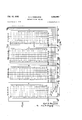
MESSAGE TIMING DEVICE Filed March 2, 1949 3 Sheets-Sheet 3 51 1;! i 519' "gea a an. L 551 515; 53: 5 1 i524i i ifig ii j 1 1/5. r- {525 r F 8 4 1535- 9 SI mom H01 fiyr/ if. Fzgason iatented 12,
UNITED STATES PATENT OFFICE 2.5%,997 MESSAGE TIMING DEVICE Syrl Ferguson, Springfield, Va. Application March 2, 1949, Serial No. 79,262
(Granted under the act of March 3, 1883, as
6 Claims.
factured and used by or for the Government for governmental purposes, without the payment to me of any royalty thereon.
This invention relates to printing telegraph apparatus, and particularly to apparatus for automatically recording the time of transmission of messages over printing telegraph circuits and the like. Since, in printing telegraphy, the sending and receiving may normally be assumed to be simultaneous, this same time record is automatically transmitted to the receiving station where it also provides a printed record of the time of receipt of the message at that point.
In the days of manual telegraphy the time transmission and reception was recorded on the message form by the operator who observed a clock, and manually recorded such observed time by whatever method in use.
Today, the manual telegraph has been-almost entirely replaced by the printing telegraph. Further, the printing telegraph has developed to a point of semi-automatic, and in some instances, automatic operation. A means of recording on the message the time of transmission or reception of messages has not kept pace with the rest of the art. It is diflicult even to hazard a guess as to the time of transmission or reception to the nearest hour, much less to the nearest minute as was the accepted accuracy in the days of manual telegraphy when messages moved in less volume and at a slower rate.
Accordingly, it is an object of this invention to provide a timing device for use with printing telegraph systems for automatically recording upon a printed message the time of transmission and reception of messages over such systems.
It is a further object of this invention to provide a message time-recording device which will record the time of transmission and reception of messages on the message form to an accuracy of plus or minus one minute.
It is also an object of this invention to provide a device which is capable of recording the time of transmission of all messages on all circuits at a center at which it is employed.
These and other objects are achieved in accordance with the invention by providing a continously available source of instant time signals.
arranged to provide a time-significant code which is introduced in the message circuit upon the completion of the transmission of a message.
In one embodiment of the present invention thesource of time signals includes: a transmitting commutator having .a plurality of circumamended April'30, 1928; 370 0. G. 757) fei'entiaily arranged conducting segments with a centrally-pivoted brush contactor operating at a constant speed; four rotary line switches each comprising a bank of a plurality of contacts, and electromagnetically actuated stepping contactors in sliding arrangement with the contacts; and a source of electrical pulses which provides electrical pulses to the switches at a rate of one per minute. The switch contacts are connected to the commutator segments to provide for the four elements of a 24-hour time signal. That is, one bank is connected to provide for the units-ofminutes digit of the time in accordance with the teletype code used, the second bank is connected to provide for the tens-of-units digit of the time, the third to provide for the units-of-hours digit of the time, and the fourth for the tens-of-hours digit of the time. In accordance with thisinvention in the stepping action of the switches due to the received one-per-minute'electrical pulses is such as to cause the first switch contactor to be advanced or stepped with each received pulse; the second operates once every ten steps of the first switch contactor; the third operates once for every 6 steps of the second contactor, and the fourth operates every 10 steps of the third contactor. Thus at any instant the position of the contactor-s, after initially preset, will be significant of the time of day.
The time-significant connections from the switches to the segments together with the grounded continuously-rotating brush arm result in the completion of an electrical circuit in accordance with the sequence of connections. Selected segments of the commutator are connected to provide the start-stop pulses required by standard printing telegraph codes, and a pulse for reestablishing normal operation.
The continuously available time significant code signals are inserted into the message circuit through the action of an interlocking arrangement. During the transmission of a message over a tape transmitter, normal conditions prevail.
Upon the completion of a message the interlock circuit through the action of relays, disables the tape -transm-ittter and connects the source of time-significant signals into the outgoing circuit. During approximately one revolution of the commuta'tor contactor there is transmitted, by means of a standard teletype code the required start and stop signals, and the instant time. The contactor then completes a circuit which operates the interlock to reestablish tape transmitter for message tape transmission.
The invention may be better understood from a consideration of the following description of an embodiment thereof when read in conlunction with the accompanying drawings, in which Figure 1 is a diagram of a transmitting commutator used for transmitting the start, stop and time record impulses in accordance with this invention.
Figure 2 is a schematic diagram of that part of the invention which is used for receiving a pulse each unit of time and to convert the time of day into the printing telegraph code used, and at the same time store this code until the following pulse has been received.
Figure 3 is a schematic diagram of a constant speed device for providing electrical pulses at the rate of one per minute.
Figure 4 is a schematic diagram of a control circuit which synchronizes the functions of time transmission with that of message transmission.
Figure 4a, is a schematic diagram of a relay circuit used for converting neutral signals into polar signals in accordance with this invention.
Figure 4b is a schematic diagram of a relay switching device which operates to complete one element of the control circuit once each revolution of the transmitting commutator brush arm.
Figure 4c is a schematic diagram of a conventional transmitter as used in printing telegraph systems to sense permutations in a prepared perforated tape and to pass these on in the form of start, stop and code pulses of the desired kind; this diagram also illustrates an embodiment of an interlocking circuit which functions to render the transmitter inoperative at the completion of a message transmission thus permitting the timesignificant code to be introduced immediately following the message.
Figure 4d is a schematic diagram of an arrangement similar to that shown in Figure 40 for use with a plurality of circuits.
Figure 5 is a simplified block diagram of the invention. 7
Referring now to the drawings and particularly to Figure 1, the reference numeral I indicates a brush arm rotatably mounted about a pivot 2 in such manner as to permit rotation in the direction indicated. A brush 3 is mounted on the end of the brush arm I and makes contact with segments of commutator 4. The segments of commutator 4 are circumferentially and sequentially arranged into groups I4 through 28. A common lead 6 connects to selected segments in each of these groups. As brush 3 contacts these selected segments, they are connected to ground through brush arm I and ground connection 5. As indicated on the diagram, asbrush 3 moves from the position shown in the direction indicated the brush 3 will contact segments 1, 8, 9, I0, II, I2 and I3 in this order and connect them to ground. Segments 29 and 30 are connected to relays 22I and 223, Figure 4, through conductors 24I and 242.
The time required for one revolution of the transmission commutator will be governed by the number of functions other than time that it is desired to transmit. These will include station identification characters in addition to pulses for clearly interlocking circuits. In one practical situation, the brush is arranged to rotate at a speed of 22.7 revolutions per minute.
' pulse each minute and to transform the actual time of day into the telegraph code and at the same time store this code until the following pulse has been received. These rotaiy line switches have banks of contacts 48, 85, I22 and I89 arranged in 6 rows of contacts, semi-circular in mounting so that double-arm wiping contacts. 42 to 41, inclusive, 19 to 84, inclusive, II6 to I2I, inclusive, and I 53 to I58, inclusive, pass successively over the different rows of contacts 54 to 18, inclusive, 9| to H5, inclusive, I28 to I52, inclusive, and I64 to I88, inclusive, by means of a ratchet wheel driven by a dog which in turn is driven by a spring (not shown) that has been extended from normal length by an electric current in the coils 49, 86, I23 and I59. When one end of the wiping contacts 42 to 41, inclusive, 19 to 84, inclusive, IIB to I2I, inclusive, and I53 to I58, inclusive, moves off of the rows of contacts 18, H5, I52 and I88, the other ends of the wiping contacts 42 to 41, inclusive, 19 to 84, inclusive, II6 to I2I, inclusive, and I53 to I58, inclusive, then move onto the rows of contacts 54, 9I, I28 and I64, thus a continuously complete rotary switch is obtained equivalent to 360 degrees of rotation.
The connection made at 2I5 in Fig. 2 provides for flexibility in the event that a different type of transmitting commutator or more than one transmitter commutator is required.
Since in the recording of the transmission and reception time of messages a 24-hour clock system is universally used, the invention incorporates features which Will provide the four elements of the time, that is, tens of hours, units of hours, tens of minutes and units of minutes. Thus the time will vary from 0001 which is one minute after midnight to 2400 which is midnight; 2400 is also synonymous with 0000 the beginning of the next day. It will be noted that the device of the present invention must be capable of providing for the first element of the time a 0, a 1 ora 2; for the second element, 0 through 9; for the third element, 0 through 5; and for the fourth element, 0 through 9.
On the rotary line switches 38, 39, and 4I of Figure 2, the wires I90 to I94, inclusive, I95 to I99, inclusive, 200 to 204, inclusive, and 205 to 209-, inclusive, are connected to the contacts successively wiped by the wiping contacts 43 to 41, inclusive, to 84, inclusive, II1 to I2 I, inclusive, and I54 to I58, inclusive, in accordance with the predetermined pulses it is desired to transmit. Switch 38 is used for the first digit or tens ofhours, 39 is used for the second digit or units of hours, 40 is for the third digit or tens of min-,
utes and M is used for the fourth digit or units of minutes.
That portion of the commutator 4 of Fig. 1 that is set aside for the selection as set up by switches 38, 39, 40 and M is shown at 20, 2|, 22 and 23 being in the order mentioned; tens of hours, units of hours, tens of minutes and units of minutes. The wiping contacts 43 to 41, inclusive, 80 to 84, inclusive, II1 to I2I, inclusive, and I 54 to I58, inclusive, are connected to wire leads 2 I0, 2I I, 2I2, 2I3 and 2 I4 are combined into wire lead 2I5 and then go to the common lead 6 of Fig. 1.
Therefore, as the wiping contacts 43 to 41, inclus'ive, 88 to '84, inclusive, II! to I2I, inclusive, and I54 to I58, inclusive, successively rest at various positions in Fig. 2, the predetermined code is transferred to the transmitting commutator 4 of Fig. 1 by wire leads I98 to I94, inclusive, I95 to I99, inclusive, 288 to 284, inclusive, and 285 to 289, inclusive, also common lead 6 of Fig. 1 is connected to the desired segments 28, 2I, 22 and 23 of Fig. l by wire lead 2 I5, wire leads 2"], 2i I, 2I2, 2I3 and ZI4 and the Wiping contacts 43 to 41, inclusive, 88 to 64, inclusive, IN to I2I, inclusive, and I54 to I58, inclusive.
Reference numeral I22 indicates a bank of contacts I28 to I52 which are arranged to provide the third element, or tens of minutes, of a 24-hour clock system. As in the previous case, the value of this third element is shown in parentheses to the right of its corresponding contact.
As indicated by the values within parentheses the contacts provide for a range of values for the third element of the time of 0 to 5. Contacts of bank I22 are connected to leads 288 to 284 show at the top of the bank. I
Reference numeral I89 indicates a fourth bank of contacts, I64 to I88 which are arranged to provide the fourth element, units of minutes, of a 24-hour clock system. Since this value will vary from 0 to 9, the contacts are arranged to provide this range. For clarity, these valuesare shown to the right of the contact involved. The contacts of bank I22 are connected to leads 285 to 289 which are shown at the top of bank I89, in Figure 2.
Contact rows I8, II5, I52, I84 to I88 are not used in the embodiment shown, since the twentyfive rows of contacts of banks 48, 85, I22 and I89 are not divisible by the number of items it is desired to transmit. It is necessary, therefore,'to provide some means whereby the wiping contacts 42 to 41, inclusive, 19 to 84, inclusive, IIS to I2I, inclusive, and I52 to I58, inclusive, after coming to rest on the unused contacts 18, I
I52, I84 to I88, are advanced to the next respective used rows of contacts 54, 9|, I28 and I64.
When wiping contact I53 comes to rest on contact row I84 an electrical current flows from the 110 volt direct current source at 2 I6 through the normal contact I6! and moving contact I68 of the stepping coil I59 thence the left-hand contact in row I84 through the wiping contact I53,
through the stepping coil I59 to the ground connection 2|! thus completing the circuit. The
stepping coil then attracts its armature with the 6 steppingspring, stepping dog and moving contact I68 attached (for purposes of clarity, the spring and dog are not shown) At some point near the end of the armature travel, the circuit through the stepping coil I59 is broken due to moving contact I68 being pulled away from the back, or normal contact I6 I. The stepping spring, having been extended from normal length, contracts and in so doing drives the stepping dog (not shown), the ratchet wheel (not shown) and wiping contact I53 to the next succeeding point of rest. The armature of stepping coil I59 is no longer attracted by the stepping coil I59 and falls back. When the armature returns enough to efiecta contact between I58 and I6I, the circuit is'ag-ain restored but this time through the left-hand contact of I85. This action continues until the Wiping contact I53 comes to rest on the next contact which does not have a source of electrical potential connected to it. In this instance wiping contact would come to rest at contact 'row I64. Condenser I63 and resistor I82 are included as normal spark protection for contacts I88 to IGI.
The clearing of wiping contacts 42, 19 and H6 over their respective unused contacts 18, H5 and I52 is accomplished in a like manner.
Pulses of electric current at one minute intervals and of short duration are present in wire lead 2I8, Figure 2. Each time a pulse of electrical current is received by Wire 218 it passes through stepping coil I59 and results in an advance of the wiping contacts, I53 to I58, one step forward. After nine such pulses are received, the wiping contacts I53 to I58 will be at rest on contact row I13.
When the tenth pulse is received, it is necessary to advance the wiping contacts II6 to 'I2I, inclusive, of switch 48 to the contact row I29 of contact bank I22, thus indicating that an interval of ten minutes has elapsed. Upon the receipt of the tenth pulse over wire 2I8 the wiping contacts I52 to I58, inclusive, will be at rest on contact row I13 or I83, considering that the starting point may have been contact row I64 or 514. With wiping contacts I53 on its respective contact in row I13 or I83 the flow of current received during a pulse over wire lead 2I8 will, in
-addition to stepping wiping contacts I53 to I58,
step the wiping contacts of the tens-of-minutes' switch 48 one step as a result of the establishment of a circuit through wire lead 2I8, wiping contact I53, left-hand contact ofcontact row I13, wire lead 2I9, stepping coil I23, to ground at 2".
When the wiping contact of switch 48 rests on contact rows I33, I39, I45 or I5I, at a time when wiping contact I53 of switch 4| rests on contact.
row I13 or I83, it is necessary that upon the receipt of the next following pulse of current over lead 2| 8, all of the wiping contacts 42 to 41, inclusive, 19 to 84, inclusive, II6 to I2I, inclusive, and I53 to I 58, inclusive, be advanced one step. Under the condition assumed above, the next impulse of electrical current over wire lead 2I8 will energize stepping coil I 59 directly and will energize stepping coil I23 by means of a circuit established through wire lead 2I8, wiping contact I53, the left-hand contactof contact row I13 or I83, wire lead 2I9, stepping coil I23 to ground connection 2I1. The stepping coils 49 and 86 will be energized and their respective wiping contacts will be moved to the next position.
by means of the same pulse in the circuit; wire lead 2I9, wiping contact llfi, left-hand contact in contact row I33, I39, I45 or I5I, wire lead 228,
and stepping coils 49 and 86 in parallel to ground 211.
As brush 3 of Fig. 1 is driven over segment 29 by brush arm 1 pivoted at 2 and grounded at 5, an electrical circuit is established between the positive terminal of electrical source 231 of Fig. 4b and ground. This circuit comprises a current limiting resistor 230, relay coil 221, wire lead 24 I, segment 29, brush 3, brush arm I and ground connection 5. The establishment of this circuit results in the movement of a relay contact 222 into contact with relay contacts 224 to 229, thus grounding contacts 224 to 229 through ground connection 223.
As brush 3 of Fig. l is driven over segment 30 an electrical circuit is established between the positive terminal of electrical source 231 and ground. This circuit comprises a current limiting resistor 232, a relay coil 233, wire lead 242, segment 30, brush 3, brush arm I and ground connection 5. The completion of this circuit moves relay contacts 234 into contact with relay contacts 235 to 240 thus grounding these through ground connections 345. It will be evident from the foregoing that relay contacts 224 to 229 and 235 to 240 are grounded once during each revolution of brush arm -I. This ground is established for a time interval equal to the time of contact of brush 3 with segments 29 and 30.
Figure 3 includes a constant speed device 249 connected to an electrical source 250. This constant speed device drives an eccentric cam which rotates at one revolution per minute. Contacts 249a are closed once each minute through the action of the eccentric cam (not shown). The closure time of contacts 249a is approximately of one second duration.
When contacts 249a close, they complete an electrical circuit comprising the positive terminal of electrical source 251, current limiting resistor 252, contacts 249a, relay coil 254, relay contacts 256 and ground 259. The completion of this circuit results in the closing of electrical contacts 211 and 260 thus completing another circuit which comprises the positive terminal of electrical source 251, contacts 211 and 260, current limiting resistor 346, relay coil 255, relay contacts 261 and 262 of relay 341, and ground connection 259. establishment of this latter circuit locks relay 253 in an operated condition.
With relay 253 in an operated condition the positive side of electrical source 251 is extended through contacts 211 and 260, current limiting resistor 265, relay coil 212, wire lead 243 to relay contact 229 of Fig. 41). Since relay contacts 224 to 229, inclusive, will be closed to ground as brush 3 of Fig. 1 moves over segment 29, it will be apparent that relay 264 will be operated each time brush 3 contacts segment 29, provided that relay 253 is in an operated condition. Once relay 264 is operated, it will lock in an operated condition by its own contacts 266 and 261.
With relays 253 and 264 locked in their operating positions the electrical circuit is further extended from electrical source 251, through current limiting resistor 269, relay coil 210, wire lead 244 and relay contact 240 of Fig. 4. Since each time brush 3 of Fig. 1 moves over segment 30 the contacts 235 to 240 of Fig. 4 will be grounded, it follows that if relays 253 and 264 are in their op- 'erated condition, relay 341 will operate as brush 3 moves over segment 29. This being the case, the operation of relay 341 breaks the holding circuit coil 255 of relay 253 at contacts 261 to 262 and breaks the pick-up circuit of relay coil 254 The of relayv 253, by means of contacts 256 to 251. This results in relays 253, 264 and 341 reverting to their unoperated condition as shown in Fig. 3.
The operation of relay 341 of Fig. 3 completes an electrical circuit from the positive terminal of electrical source 251, through current limiting resistor 216, relay coil 211, contacts 262 to 263 and 251 to 258 to ground 259. The completion of this circuit operates relay 213 closing contacts 214 to 215. This connects the positive terminal of electrical source 251 through wire lead 218, to the stepping coils 159, I23, 86 and 49 of Figure 2. These coils are then selectively connected to the source of potential through the action of wiping contacts 42, 19, H6 and 153.
In Figure 4a are shown five polar relays of a variety commonly used in printing telegraph equipment. One type is manufactured by the Western Electric Company under the type number 255-A. These relays have two windings, and may be used in various ways. One way is to apply a certain value of current through one of the windings so that the moving contact is pulled toward the fixed contact which is to be used for the spacing condition during the transmission of the code used. A higher value of current is then used in the other winding during a marking condition. Thus when a mark signal is impressed, the current in the second winding in effect, overcomes the efiects of the spacing or bias current in the first winding resulting in a movement of the movable contact against the contact used for the marking condition. This condition can be reversed so that the relay is biased to a mark condition by means of a fixed current in one winding and when a space condition is desired, a higher current is made to flow through the other winding.
to provide outputs for multiple circuits from the transmitting commutator of Fig. 1.
The moving contact 28I of relay 218 of Fig. 5 is held in contact with fixed marking contact 283 of relay 218 by means of an electrical current from a source of direct current potential through wire lead 300, current limiting resistor 284, relay coil 280 to ground at 305. The relay contacts 281 and 283 remain closed when brush 3 in Fig. 1 makes contact with a segment or segments of commutator 4 which are not connected to common lead 6.
As brush 3 of Fig. 1 moves onto a. segment of commutator 4 that is connected to common lead 6, such as segment 1, for example, a larger electrical current, than fiows in relay coil 28, will flow from the electrical source through wire lead 300, through current limiting resistor 285, relay coil 219, common lead 6, brush arm 1 to ground connection 5. This larger current through relay coil 219 is poled in such a manner that it causes relay armature 281 to make connection with fixed spacing contact 282.
It will be seen by referring to Fig. 4a that when contacts 281 and 283 are connected together for the marking condition, the marking coils 290 and 76 contact 281.
The resistors 359 and 351 and condensers 248 and 249 are included as normal spark protection for these contacts.
It will be seen that the signals as transmitted by the transmitting commutator of Fig. l are reproduced at wire pairs 303 and 394. Additional reproductions may be had simply by adding relays such as 288 and 299.
Figure 4c shows a conventional type of transmitter 396 such as used in printing telegraph systems to sense permutations in a prepared tape. Transmitter 306 passes this sense on in the form of start, stop and code pulses of the code used.
During operation, when a perforated tape is fed into the transmitter, a signal is transmitted to line pair 311 through the action of contacts 391. Under normal operating conditions, the line pair 311 will be complete. It will not be broken as indicated by broken line at 313; nor will wire pair 303 be connected at 313. The dotted lines are shown to indicate the points at which the time signal is introduced into the message transmitting circuit. When used for message transmission without the present invention the lines 313 and 319 are complete.
As long as a message tape remains in the transmitter 306, the transmitter will continue to operate because of a control current furnished over wire pair 312 to the clutch magnet 308. This clutch magnet has a pair of contacts, in one of the wires of wire pair 312, which open upon the completion of the run of the message tape through the transmitter. For the purposes of the present invention, control pair 312 is broken at 310 and extended by means of wire pair 344. Wire pair 344 is connected to a control circuit which comprises relays 315, 316, 311 and 318. These relays are of a well-known kind. Relay 315 may be of the type manufactured by the C. P. Clare Co., Chicago, Illinois, under Catalog No. -2294; relays 316, 311 and 318 may be of the type manufactured by the Western Electric Company under Catalog No. E-64'10.
Assume that transmitter 396 is in operation transmitting a tape message. Under this condition the control circuit holds the transmitter in running condition and the contacts 399 are closed.
Upon the completion of the message tape, contacts 339 open, de-energizing coil 306. With contacts 309 separated, coil 322 is de-energized opening contacts 320 to 321 and closing contacts 319 to 329 of relay 315. The short circuit across condenser 335 which consisted of ground connection 320 to 321, relay coil 325, and contacts 342 to 343 is now removed.
With the closing of contacts 319 to 320, condenser 335 receives a surge of charging current from electrical source 314. This charging current passes through relay coil 325, contacts 342 to 343 to ground, thus energizing relay 316. Contacts 323 to 324 of relay 316 close establishing a circuit from the positive terminal of electrical source 314, through contacts 323 to 324, current limiter resistor 326, relay coil 321, non-operated 10 contacts 346 to 341 to ground. Relay 316 is caused to lock up in an operated condition opening the transmitter control circuit 312 at contacts 328 to 329 of relay 316. Transmitter 306 is now disabled and cannot run.
With relay 316 in an operated condition, the positive terminal of electrical source 314a is extended through relay contacts 323 to 324, current limiting resistor 339, relay coil 333, wire lead 246 to contact 223 of Fig. 4. Since contacts 224 to 229 are grounded each time brush 3 of Fig. 1 passes over segment 29, relay 311 will also operate provided relay 316 is in an operated condition.
When relay 311 operates it locks into an operated condition upon itself by means of contacts 334 and 331. The operation of relay 311 opens contacts 331 to 332 thereby removing the short circuit from wire pair 303. Since signals are transmitted by the transmitting commutator of Fig. 1 and are present on wire pair 303, it follows then that the signal as transmitted by the transmitting commutator will enter the message circuit 311 at point 313. This amounts to breaking the message circuit 31 1 and inserting a wire pair 393 therein.
The operation of relay 311 opens the shunt to ground of relay coil 339 by opening contacts 336 to 331. After approximately 360 degrees of rotation of brush arm 1 of Fig. l, or at the end of the time transmission, the brush 3' passes over segment 29 and in so doing operates relay 318 completing the circuit from the positive terminal 314 through current limiting resistor 338, relay coil 339, wire lead 248, contact 231 to ground at 234.
Theoperation of relay 318 opens the holding coil circuit of relay 316 at contacts 340 to 341. It also opens the pick-up coil circuit of relay 316 at contacts 342 to343. The relays 316, 311 and 318 are, therefore, returned to their unoperated condition as shown on the diagram. Transmitter 396 is again operative as the control circuit is remade at contacts 328 to 329.
Figure 4d shows an arrangement which is equivalentto that of Figure 4c and illustrates the manner in which this invention may be used in connection with several circuits simultaneously. The operation of the circuit of Figure 4d is the same as that of Figure 40.
Figure 5 illustrates by means of a block diagram the operational relation of the several elements comprising this invention. Reference numeral 396 represents a conventional permutation-code tape transmitter which may be employed in a communication system incorporating mytiming device. Reference numeral 350 represents a source of time signals and includes the previously-described commutator, line switches and source of periodic electrical pulses as shown by Figures 1, 2 and 3. Block 351 represents the control circuit of this invention and includes previously described elements of Figures 4, 5 and 6. 355, 356, 351 and 356 represent the electrical interconnection of elements of blocks 305, 359, 351 and 352. Block 352 represents the changeover means of my invention and includes the contacts of relay 311 for opening and closing circuit 311 at 313, and those contacts of relay 316 which open the code transmitter control circuit. The outgoing circuit 311 corresponds to line pair 311 of Figure 6. 354 represents the receiving station to which the message is being transmitted.
A simplified description of the operation of my invention based on Figure 5 is as follows: With a message tape running through tape transmitter.
306 in the usual manner, the output of transmitter 306 will feed directly into the outgoing circuit 3| I and then to receiving station 354. At the instant that the message tape completes its run through transmitter 306, control circuit 35! through 351 disables transmitter 306 and inserts into the outgoing circuit 3 through 356 and 358, permutation code signals from 350; through 355 and action of means 352, representing the instant time of day. This time is transmitted to the receiving station 354 immediately following the transmission of the message thus providing the receiving station with time of transmission. Since in printing telegraphy and in all forms of automatic communications systems, the time of receipt of a message is substantially the time of transmission, the time that appears on the message will be the time of transmission. Further, since it is the usual practice to have a home copy at the transmitting station of all transmissions, a record is thus available of the transmission time of all messages from the station.
In tape relay operation it is a practice to have a monitor printer usually a tape type reperforator ride the circuit to give a complete running history of what goes out of the transmitter. Where tape relay operation is not used a page type monitor would then ride the circuit and provide a record.
From the above, it will be apparent to those skilled in the printing telegraph art that at the receiving station the time that is transmitted will appear on the tape or page that is made there. When the message is retransmitted, two times will then appear one below the other and as the message is again retransmitted, we will say relayed a half dozen times, the time of transmission will appear on the home copy.
It should be understood that the above embodiment has been shown and described to illustrate the features and operation of this invention. It will be apparent to those skilled in the art that many changes and variations in the specific form of the apparatus herein disclosed may be resorted to without'departing from the essentials of the invention.
1. In a printing telegra h system including means for transmitting and means for receivin telegraph messa es, said means for transmitting including a tape transmitter utilizing a permutation message code, a device for automatically recording the time of transmission and reception of said messages comprising a continually operative source of signals significant of instant time, and an automatically operating control means; said source of signals including an electromechanical distributor comprising a series of conductor segments insulated from each other, a continuously moving electrical contactor in sliding relation to said segments, a source of periodic electrical pulses, a switching circuit connected to said source of electrical pulses, said switching circuit including a plurality of banks of contacts and brush contactors movable with respect to said contacts and being selectively responsive to said pulses, electrical connections between said contacts and said segments in accordance with said permutation code to provide the elevents for the instant time, whereby the position of said brush contactors on the contacts is significant of said time; said control means connected between said tape transmitter and said source of signals and including means for automatically disabling the tape transmitter after the completion of a message and including also means for inserting said time signals into ill? outgoing circuit, thereby providing a time record of the transmission of said message, said time also being substantially the time of receipt of said messages.
2. The device according to claim 1 in which said series of conducting segments includes segments for supplying a terminal signal and in which said control circuit includes means responsive to said terminal signal for reconnecting said transmitting means to said transmission circuit at the completion of the transmission of the instant time, thus resetting the system for the next message.
3. In a printing telegraph system, including a transmitting means for transmitting permutation code signals, and an outgoing transmission circuit, a device for automatically inserting into said transmission circuit the time of transmission of a message, said device comprising a continually operating source of signals significant of the instant time, and control means; said source of signals including a commutator comprising a series of conductor segments insulated from each other, a continuously moving electrical contactor in sliding relation to said segments, a source of electrical pulses, said switching circuit connected to the source of electrical pulses, said switching circuit including a plurality of contacts and brush contactors movable with respect to said contacts and being selectively responsive to said pulses, electrical connections between said contacts and said segments in accordance with said permutation code to provide the elements for the instant time, whereby the position of said brush contactors on the contacts so significant of said time, and a time signal output circuit connected to said commutator segments; said control means including magnetically operated means for automatically disconnecting said transmitting means from the transmission circuit upon the completion of a message, and for connecting the time signal circuit to said transmission circuit, whereby the time of transmission of said message is transmitted immediately after the transmission of a message.
4. The device according to claim 3 in which said series of conducting segments includes segments for supplying a terminal signal, and in which said control circuit includes means responsive to said terminal signal for reconnecting said transmitting means to said transmission circuit at the completion of the transmission of the instant time, thus resetting the system for the next message.
5. In a printing telegraph system means for automatically recording the time of transmission of messages over an outgoing circuit, said means comprising: an electromechanical distributor, said distributor comprising a circular series of conducting segments insulated each from the other, a continuously operating electrical contactor in sliding relation to said segments; a source of periodic pulses of electrical energy; switching means responsive to said periodic pulses, said switching means comprising a plurality of banks of contacts and brush contactors movable longitudinally relative to the banks of said contacts; electrical connections between said contacts and said segments, said connections made in accordance with a time-significant code; said switching means being responsive to said received pulses, whereby the position of said brush contactors on the contacts is significant of the time of day; control means; said control means includ g aeans'connected to the distributor and.
the outgoing circuit for automatically interrupting the outgoing circuit at the completion of a message tape, and for inserting the timesignificant code into said outgoing circuit, thereby providing a record of the time of transmission of said message.
6. In a message transmitting system, including a transmitting unit and an outgoing transmission circuit a device for recording the time of transmission of messages comprising: a continuously-operating source of instant time signals including an electromechanical distributor comprising a series of conductor segments insulated from each other, an electrical contactor in sliding relation to said segments said electrical contactor moving at a substantially constant speed, a source of periodic electrical pulses, a magnetically operated switching means connected to said source of electrical pulses, said switch ing means including a plurality of banks of contacts and brush contactors movable with respect to said contacts and being selectively responsive to said pulses, electrical connections between said contacts and said segments in accordance with predetermined time units, to provide the elements for the instant time, whereby the position of said brush contactors on the contacts is significant of said time; said source having an output circuit; an automatic control circuit comprising a plurality of magnetically operated means for disconnecting said transmitting unit from said outgoing circuit, at the completion of a message and also means for connecting said output circuit to said transmission circuit, whereby the time of transmission of said message is transmitted immediately following the transmission of a message.
SYRL K. FERGUSON.
REFERENCES CITED The following references are of record in the file of this patent;
UNITED STATES PATENTS
Priority Applications (1)
| Application Number | Priority Date | Filing Date | Title |
|---|---|---|---|
| US79262A US2584997A (en) | 1949-03-02 | 1949-03-02 | Message timing device |
Applications Claiming Priority (1)
| Application Number | Priority Date | Filing Date | Title |
|---|---|---|---|
| US79262A US2584997A (en) | 1949-03-02 | 1949-03-02 | Message timing device |
Publications (1)
| Publication Number | Publication Date |
|---|---|
| US2584997A true US2584997A (en) | 1952-02-12 |
Family
ID=22149435
Family Applications (1)
| Application Number | Title | Priority Date | Filing Date |
|---|---|---|---|
| US79262A Expired - Lifetime US2584997A (en) | 1949-03-02 | 1949-03-02 | Message timing device |
Country Status (1)
| Country | Link |
|---|---|
| US (1) | US2584997A (en) |
Cited By (6)
| Publication number | Priority date | Publication date | Assignee | Title |
|---|---|---|---|---|
| US2667533A (en) * | 1950-05-10 | 1954-01-26 | Teletype Corp | Automatic message switching system |
| US2677013A (en) * | 1952-02-05 | 1954-04-27 | Teletype Corp | Numbering transmitter |
| US2849704A (en) * | 1954-06-28 | 1958-08-26 | Cons Electrodynamics Corp | Data processing system |
| US3134848A (en) * | 1961-03-14 | 1964-05-26 | Western Union Telegraph Co | Waystation selection network |
| US3144509A (en) * | 1961-07-03 | 1964-08-11 | U S Naval Comm Station | Automatic time transmitter |
| US3962548A (en) * | 1973-11-07 | 1976-06-08 | Stone Jr Wayne B | Direct readout exhibitor for determining long distance telephone charges |
Citations (6)
| Publication number | Priority date | Publication date | Assignee | Title |
|---|---|---|---|---|
| US1872842A (en) * | 1930-06-08 | 1932-08-23 | Siemens Ag | Call recording and charging system |
| US1972289A (en) * | 1928-01-10 | 1934-09-04 | Chauveau Louis Lucien Eugene | Automatic transmitter key for distress signals |
| US2357297A (en) * | 1940-07-13 | 1944-09-05 | Teletype Corp | Printing telegraph system |
| US2404654A (en) * | 1942-02-07 | 1946-07-23 | Teletype Corp | Toll metering system |
| US2412198A (en) * | 1943-09-24 | 1946-12-10 | Bell Telephone Labor Inc | Telegraph switching system |
| US2502654A (en) * | 1947-04-07 | 1950-04-04 | Teletype Corp | Selective signaling system and apparatus |
-
1949
- 1949-03-02 US US79262A patent/US2584997A/en not_active Expired - Lifetime
Patent Citations (6)
| Publication number | Priority date | Publication date | Assignee | Title |
|---|---|---|---|---|
| US1972289A (en) * | 1928-01-10 | 1934-09-04 | Chauveau Louis Lucien Eugene | Automatic transmitter key for distress signals |
| US1872842A (en) * | 1930-06-08 | 1932-08-23 | Siemens Ag | Call recording and charging system |
| US2357297A (en) * | 1940-07-13 | 1944-09-05 | Teletype Corp | Printing telegraph system |
| US2404654A (en) * | 1942-02-07 | 1946-07-23 | Teletype Corp | Toll metering system |
| US2412198A (en) * | 1943-09-24 | 1946-12-10 | Bell Telephone Labor Inc | Telegraph switching system |
| US2502654A (en) * | 1947-04-07 | 1950-04-04 | Teletype Corp | Selective signaling system and apparatus |
Cited By (6)
| Publication number | Priority date | Publication date | Assignee | Title |
|---|---|---|---|---|
| US2667533A (en) * | 1950-05-10 | 1954-01-26 | Teletype Corp | Automatic message switching system |
| US2677013A (en) * | 1952-02-05 | 1954-04-27 | Teletype Corp | Numbering transmitter |
| US2849704A (en) * | 1954-06-28 | 1958-08-26 | Cons Electrodynamics Corp | Data processing system |
| US3134848A (en) * | 1961-03-14 | 1964-05-26 | Western Union Telegraph Co | Waystation selection network |
| US3144509A (en) * | 1961-07-03 | 1964-08-11 | U S Naval Comm Station | Automatic time transmitter |
| US3962548A (en) * | 1973-11-07 | 1976-06-08 | Stone Jr Wayne B | Direct readout exhibitor for determining long distance telephone charges |
Similar Documents
| Publication | Publication Date | Title |
|---|---|---|
| US2357297A (en) | Printing telegraph system | |
| US2584997A (en) | Message timing device | |
| US1864074A (en) | Telegraph signaling system | |
| US2116549A (en) | Telegraph system | |
| US2708216A (en) | Transmitter suppressor | |
| US2292404A (en) | Collateral control by tape slack | |
| US2404654A (en) | Toll metering system | |
| US2013171A (en) | Measured service telephone system | |
| US2405991A (en) | Secrecy system | |
| US2373970A (en) | Conversion of start stop signals to synchronous type signals and vice versa | |
| US2248583A (en) | Code translating mechanism | |
| US2339293A (en) | Telegraph transmitter | |
| US1533171A (en) | Telegraph system | |
| US1851956A (en) | Method of and apparatus for signaling in high speed telegraph systems | |
| US2020953A (en) | Telephone system | |
| US1856985A (en) | Regenerative repeater for start-stop systems of automatic telegraphy | |
| US2688738A (en) | Receiver for remote supervisory and control systems | |
| US2000765A (en) | Communication system | |
| US2271653A (en) | Divided multiplex channel | |
| US1864303A (en) | Radio printing telegraph system | |
| US2419581A (en) | Printing telegraph station identification transmitter system | |
| US3017460A (en) | Multiple pulse communication system | |
| US2401877A (en) | Enciphering and deciphering system | |
| US2248923A (en) | Communication system | |
| US1400493A (en) | Telegraph system |