US2575673A - Washing machine of the cylindrical container, end discharge type - Google Patents
Washing machine of the cylindrical container, end discharge type Download PDFInfo
- Publication number
- US2575673A US2575673A US702537A US70253746A US2575673A US 2575673 A US2575673 A US 2575673A US 702537 A US702537 A US 702537A US 70253746 A US70253746 A US 70253746A US 2575673 A US2575673 A US 2575673A
- Authority
- US
- United States
- Prior art keywords
- container
- washing machine
- door
- cylindrical tank
- laundry
- Prior art date
- Legal status (The legal status is an assumption and is not a legal conclusion. Google has not performed a legal analysis and makes no representation as to the accuracy of the status listed.)
- Expired - Lifetime
Links
Images
Classifications
-
- D—TEXTILES; PAPER
- D06—TREATMENT OF TEXTILES OR THE LIKE; LAUNDERING; FLEXIBLE MATERIALS NOT OTHERWISE PROVIDED FOR
- D06F—LAUNDERING, DRYING, IRONING, PRESSING OR FOLDING TEXTILE ARTICLES
- D06F21/00—Washing machines with receptacles, e.g. perforated, having a rotary movement, e.g. oscillatory movement
- D06F21/02—Washing machines with receptacles, e.g. perforated, having a rotary movement, e.g. oscillatory movement about a horizontal axis
- D06F21/04—Washing machines with receptacles, e.g. perforated, having a rotary movement, e.g. oscillatory movement about a horizontal axis within an enclosing receptacle
Definitions
- This invention relatesiv to 1. washing -gmachincs and, in particular-, ita-relates v,tocwashing machinesof the commeroalzztypaicin:which: aivperforated container iswrotatedvwithin an outer cylinder.
- the invention relates to a com-l flashal Washing machine in -whichiaundry'fmay be fed into a horizontally disposed cylindrical container through one ⁇ end ythereof, and including means for elevating-one end :ofnthegwashing ma-f chine for the ⁇ purpose of ,ejecting laundry from the machine; f Y YIn washing machines of thecommercialty-Pe, it is conventionalpractice to provide-an inner cyl-V inder rotatably.
- the support forthewasliing machine includes a hinge ⁇ at one jend, and means at the opposite end for elevating one end of the washing machine.V *i Y ""WASHINGfMACnINE oF-THE cYLINDmc-gr, i Q
- Figure 1l is an elevational View in longitudinal section of a washing machine embodying the fea# tures of my invention
- Figure 2 is an end elevational view thereof, partly broken away, and partly in section; and, Figure 3 is a detailed view, in sectionh of a door locking mechanism taken alongV lines lII-III of Figure 2.
- nels 3 which serveas-afbase forsupporting the outer cylinder l, Amain page t0. which. themachine is nii/@tally supgcrted comprises arbeiter; channelsci. and4 llt ..;;l ⁇ hese channels rest umn and are preferably attached to a iioor, orsimilar support.
- brackets Il andml2 are near one end*v of each of the ⁇ Vchannels 9 and E@ isvattached brackets Il andml2respecl tively; which serve, asi-a ⁇ hinge .or Divan linnn whichgthe washing-machine may betppd .
- a hinge pin lextends through the bracket@V Il and I2 and through the pair of channels 8- to pin I3. This results in a tipping action of the ⁇ entire Washing machine.
- a bracket 46 is attached to the angle 5, and an eye screw 41 is pivoted to the bracket 4B.
- a lock arrangement is provided for securing the idoor in closed position.' i 1o
- An end enclosure is also provided for the inner container 2. This end enclosure comprises a plate 5U having inwardly tapered edges 5I adapted to cylinder I, a conduit 2E extending through the plate 3 is employed. A portion of the conduit 2D may be of iiexible construction so as to permit elevation of the washing machine while main- Y taining the Water connection.
- a quick dump valve of conventional type is utilized. Essentially, this valve comprises a sealing member 22 having a handle 23 attached thereto and pivotally mounted on a bracket 24 Ysecured to the container I.
- a hand operated latch 25 functions to maintain or release the valve from its engaging position, and a spring 26 normally maintains the latch 25 in locked position.
- a drain 2'I Directly below the dump valve is a drain 2'I having an enlarged top portion 25 adapted to enclose the principal portion of the sealing member 22 of the dump valve. The drain portion 28 is disengaged from the cylinder I so as to permit tipping movement of the washing machine without accompanying movement of the drain.
- the container 2 Rotatably mounted within the container I is the inner cylindrical container 2 formed of perforated sheet metal.
- the container 2 includes a plurality of ribs 23 suchY as are conventionally employed'in Washing machines of the cylindrical type.
- the container 2 is open at one end and is closed at the opposite end by means of a plate 3U.
- engagesr with the closed end of the container 2 by means of being attached to inserted plates 32 fastened in the well of the V-shaped ribs 29.
- the Bange 3I is supported by a shaft 33 mounted in a bearing 3e held in a fixed position by means of a bracket 35 attached Vto the end plate 3.
- a pulley 35 keyed to the shaft 33 is driven through belts 3'! from a pulley 38 attached to a motor 35.
- the motor 39 is supported by a plate 43 secured to the upper surface of the channel 8. *o
- the ccntainer 2 may be driven from the motor 33 While the washing machine is in either a horizontal or tipped position.
- bearing supports 4i attached to the inner surface of the outer cylinder I and adapted to form a sliding contact with the outer surface oi the inner cylinder 2.
- These bearing blocks 4I may be composed of a suitable bearing material such, for example, as lignum vitae. These bearing blocks, when positioned in spaced relation, serve to remove the strain on the principal drive support for the container, and will reduce vibration of the container when the container is being rotated with an open end.
- I In order to form a Water-tight enclosure for the outer container I, I provide a door 42 having hinges 43 and 44 attached to the door and to the reinforcing angle 5 which circumscribes 'the container I. A sealing ring 45 lying within the marfrom the container 2.
- the plate 50 is supportedby a ange 52 forming a part of a shaft 53.
- the shaft 53 is rotatably supported f by a bearing ⁇ blockf54 attached to the door 42.
- a collar 55 maintains the shaft 53 in proper axial position.
- This means of enclosing the end of the inner container 2 provides, in addition to the enclosure, a support for the end of the inner container 2.A this manner, it'is possible to rotate the inner container 2 at relatively high speeds for the purpose of semi-drying laundry by means or" expressing the watertherefrom by centrifugal force.
- the door 42 is opened and the dry laundry is positioned within the container 2. Thereafter the door is closed and aV desired quantity of water is introduced through the conduit A suitable detergent may be placed initially in the conf tainer or it maybe introduced through an additional rconduit (notfshown).
- the motor 39 is started and the inner container is rotated for the washing cycle. Ifdesired, the motor may be of a reversible'type 'so as to result in a given number of turns of the container 2 in one direction, and ⁇ a" ⁇ s'iiila'r numbern ofturns in the opposite direction.
- the dump valve is actuated allowing the water to run out of the container I. Thereafter, clear water is introduced into the container followed by a rinsing cycle.
- the dump valve is again actuated and the ⁇ water is permitted to run down the dr ⁇ a ir1 ,Throughoutthese operations, the container may be rotated continuously. If desired, the motor 39 may be increased in speed so as to dry the laundry, partially, due to centrifugal action.
- the door 42 is next opened and the J'aCk I4 is actuated to elevate one end of the washing machine.
- a receptacle maybe positioned at the outletend ofthe washing machine to receive the laundry which is ejected from the machine.
- a washing machine comprising a horizontally disposed cylindrical tank having an open end, a perforated container rotatable within the cylindrical tank and having an open end the diameter of which is substantially equal to the diameter of the perforated container, means for rotating the perforated container, a support upon which the cylindrical tank rests, a hinge for joining the open end portion of the cylindrical tank to the support, means for elevating the cylindrical tank at the end opposite to its openk end, a, door adaptable for closing the open end of the cylindrical tank and the rotatable container, said door comprising separate walls for engagement with the cylindrical tank and the rotatable container, one of the walls of said door being positionable in stationary relationship with the cylindrical tank and the other wall being rotatable with the perforated container, and sealing means positioned between the outer marginal portion of said door and the edges of the open end of said cylindrical tank, whereby when the cylinder is rotated, the doors open, and the closed end of the cylindrical tank elevated, the
- laundry within the perfo-rated container progressively and unrestrictedly moves out of the perforated container and is discharged from the washing machine.
- a washing machine comprising a horizontally disposed cylindrical tank having an open end, a perforated container rotatable within the cylindrical tank and having an open end the diameter of which is substantially equal to the diameter of the perforated container, means for rotating the perforated container, a drain valve attached to the underside of the cylindrical tank, a drain in registry with the drain valve and disconnected with the cylindrical tank, a support, means for pivotally connecting the door end of the cylindrical tank to the support, and means for elevating one end of the ycylindrical tank, said elevating means comprising a uid operable cylinder having one end attached to the end of the cylindrical tank which is opposite to said door, and the other end of the iluid operable cylinder being attached to said support, whereby when the cylinder is rotated, the doors open, and the closed end of the cylindrical tank elevated, the laundry within the perforated container progressively and unrestrictedly moves out of the perforated container and is discharged from the Washing machine.
- a washing machine comprising a horizontally disposed cylindrical tank having an open end, a perforated container rotatable within the cylindrical tank and having an open end the diameter of which is substantially equal to the diameter of the perforated container, means for rotating the perforated container, a drain valve attached to the underside of the cylindrical tank, a drain in registry with the drain valve and disconnected with the cylindrical tank, a door hinged to said tank having portions thereof for engagement with the open end edges of said tank and said container when the door is in its closed position and for disengagement therewith when the door is in its open position, said door comprising separate walls for engaging with the cylindrical tank and the rotatable container, a support, means for pivotally connecting the door end of the cylindrical tank to the support, and means for elevating one end of the cylindrical tank, said elevating means comprising a fluid operable cylinder having one end attached to the end of the cylindrical tank which is opposite to said door, and the other end of the uid operable cylinder being attached to said support, whereby when the cylinder is rotated, the
- a washing machine comprising a horizontally disposed cylindrical tank having an open end, a perforated container rotatable within the cylindrical tank and having an open end the diameter of which is substantially equal to the diameter of the perforated container, means for rotating the perforated container, a drain valve attached to the underside of the cylindrical tank, a drain in registry with the drain valve and disconnected with the cylindrical tank, a, door hinged to said tank having portions thereof for engagement with the open end edges of said tank and said container when the door is in its closed position and for disengagement therewith when the door is in its open position, said door comprising separating walls for engaging with the cylindrical tank and the rotatable container, one of the Walls of said door being positionable in stationary relationship with the cylindrical tank and the other wall being rotatable with the perforated container, a support, means for pivotally connecting the door end of the cylindrical tank to the support, and means for elevating one end of the cylindrical tank, said elevating means comprising a fluid operable cylinder having one end attached to the end of the cylindrical tank which is
Landscapes
- Engineering & Computer Science (AREA)
- Textile Engineering (AREA)
- Accessory Of Washing/Drying Machine, Commercial Washing/Drying Machine, Other Washing/Drying Machine (AREA)
Description
3 7 6 5 7 5 2 L @E I mw mT E HG% R9 cm1 RE C l EHSO LTIl LFD .IOD M No .EEO N HT. ,d HRG mmm MIF GM NN MO SC A W l 5 9 1.. 0 2 V M ELEVATED Posmo INVENTOR HERMAN MILLER BY? ATTORNEY Patented Nov. 20L 19551 r: This invention relatesiv to 1. washing -gmachincs and, in particular-, ita-relates v,tocwashing machinesof the commeroalzztypaicin:which: aivperforated container iswrotatedvwithin an outer cylinder.
More particular1y,;the invention relates to a com-l mercial Washing machine in -whichiaundry'fmay be fed into a horizontally disposed cylindrical container through one` end ythereof, and including means for elevating-one end :ofnthegwashing ma-f chine for the` purpose of ,ejecting laundry from the machine; f Y YIn washing machines of thecommercialty-Pe, it is conventionalpractice to provide-an inner cyl-V inder rotatably. mountediwithinvan outer cylin l der, and to provide doors through thecylindrical surface ofthe cylinder for thepurpose ofloading and unloading the machinefwith laundry- ,-:'-Ihe loading of the machine ,with laundry -isnot-very difficult,V but the unloading :operation-:involves considerable manual labor.-This is because the g laundry is wet and it is necessary to manually grasp and lift severalahundredpoundscf wet laundry fromthe machine-after each cycle of its operation. In accordance with the practice of myf inlvention, I provide a-commercial washing machine .having a rotatable innergcylinder and a stationary outer 4cylinder. @ne foffthe-ends-of both cylinders are openv and these openings are closeable by a hingeddouble door,- .one portion of the door being rotatable with, the inner cyl-b index, while-the Youter portignff thc. @gonfia-gtationary and is adapted to close in'csealinglenf gagementwiththe outer cylinder. .The-drive and the principal supportjorthe inner cylinder is Y located at oneend -only ,of the machine and opposite to the door end. The support forthewasliing machine includes a hinge` at one jend, and means at the opposite end for elevating one end of the washing machine.V *i Y ""WASHINGfMACnINE oF-THE cYLINDmc-gr, i Q
" CONTAINERS-END DISHARG-E-TYIVE A washing machine of this description provides a number of novel features. dFor;flaxample,the end doors of themachine lmay@ wungeonen and dry laundrymaylbceasilvvlca ed.; into' the open end vof .the cylindrical containert Thereafter, the door is closed and water, together; with a suitable detergent, is fedintothe-container. Afterthe proper washing andrinsingcycle is completed the end Adoors areopenedand one vend of the washingmachine is eleyated. ,'The inner cylindrical -ntaingr @sz-,mined -Wliil :thegraaf chine isin vits, tipped pesitiorna` Thigpermits the Wet laundry to drop out of the end of theinner container into.a..receptacle .positioned togreceive the laundry.Vv lfdesired;beforeltheenddgors are a constitute the hinge.
opened,..the,inner containermay ,berotate idly so as to express, thewater fromvthedaundij'y due to .centrifugal force, thus causing the laundry to. besemidried, before it is ejected y from the machine. s s f. Y'
It is therefore among.the. advantagesofmy invention to provide a Washing machine which is self dumping; to provide a Washing machine which permits a reduction in manual labor; `to provide a Washing machinewhich eliminatesJ the use of conventionaldoors on the cylindrical sur; faces of the cylinder,k thereby eliminating klthe need of registry of the doors and eliminatingY the additional expense involved inthe manufacture of such doors; to provide awashing p machine which may be positioned so that the washed laundry may be dropped directly from. the` washing machine to a receptacle; and, to provide a wash-` ing machine of the character described, which mayY be manufactured economically and which will function emciently throughout its cycle of operation.
These and other objects and advantages will appear more fully in the following detailed description when considered in connection with the accompanying drawing, in which; 1
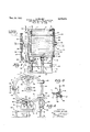
Figure 1l is an elevational View in longitudinal section of a washing machine embodying the fea# tures of my invention;
Figure 2 is an end elevational view thereof, partly broken away, and partly in section; and, Figure 3 is a detailed view, in sectionh of a door locking mechanism taken alongV lines lII-III of Figure 2.
With reference to the drawing and, in par# ticular, to Figure l, I show an Yembodiment of my invention in the form of a commercial washing machine comprising essentially 'an outer cylindrical container I and an inner container 2: The outer container is provided with an end wall 3. Reinforcing structural members tand@ are attached to the container l and to frames 6 and 1, respectively, and to apair of horigontahhan:
nels 3 which serveas-afbase forsupporting the outer cylinder l, Amain page t0. which. themachine is nii/@tally supgcrted comprises arbeiter; channelsci. and4 llt ..;;l`hese channels rest umn and are preferably attached to a iioor, orsimilar support. Near one end*v of each of the `Vchannels 9 and E@ isvattached brackets Il andml2respecl tively; which serve, asi-a `hinge .or Divan linnn whichgthe washing-machine may betppd .A hinge pin lextends through the bracket@V Il and I2 and through the pair of channels 8- to pin I3. This results in a tipping action of the` entire Washing machine.
For the purpose of introducing waterinto the ginal edge of the door 42 engages with the edge of the outer cylinder I to constitute a seal and thus form a water tight container. As shown in Figure 3, a bracket 46 is attached to the angle 5, and an eye screw 41 is pivoted to the bracket 4B. By means of a hand operated nut 48 and an extension plate 49 projecting from the door 42, a lock arrangement is provided for securing the idoor in closed position.' i 1o An end enclosure is also provided for the inner container 2. This end enclosure comprises a plate 5U having inwardly tapered edges 5I adapted to cylinder I, a conduit 2E extending through the plate 3 is employed. A portion of the conduit 2D may be of iiexible construction so as to permit elevation of the washing machine while main- Y taining the Water connection.
At the lower portion of the container`r I` is an outlet aperture 2 I. As shown in Figure 2, a quick dump valve of conventional type is utilized. Essentially, this valve comprises a sealing member 22 having a handle 23 attached thereto and pivotally mounted on a bracket 24 Ysecured to the container I. A hand operated latch 25 functions to maintain or release the valve from its engaging position, anda spring 26 normally maintains the latch 25 in locked position. Directly below the dump valve is a drain 2'I having an enlarged top portion 25 adapted to enclose the principal portion of the sealing member 22 of the dump valve. The drain portion 28 is disengaged from the cylinder I so as to permit tipping movement of the washing machine without accompanying movement of the drain.
Rotatably mounted Within the container I is the inner cylindrical container 2 formed of perforated sheet metal. The container 2 includes a plurality of ribs 23 suchY as are conventionally employed'in Washing machines of the cylindrical type. The container 2 is open at one end and is closed at the opposite end by means of a plate 3U. A trunnion or flange 3| engagesr with the closed end of the container 2 by means of being attached to inserted plates 32 fastened in the well of the V-shaped ribs 29. The Bange 3I is supported by a shaft 33 mounted in a bearing 3e held in a fixed position by means of a bracket 35 attached Vto the end plate 3. A pulley 35 keyed to the shaft 33 is driven through belts 3'! from a pulley 38 attached to a motor 35. The motor 39 is supported by a plate 43 secured to the upper surface of the channel 8. *o
In accordance with this arrangement, the ccntainer 2 may be driven from the motor 33 While the washing machine is in either a horizontal or tipped position.
To assist in supporting the free end of the container 2, I provide, near the freeV end of the container, three or more bearing supports 4i attached to the inner surface of the outer cylinder I and adapted to form a sliding contact with the outer surface oi the inner cylinder 2. These bearing blocks 4I may be composed of a suitable bearing material such, for example, as lignum vitae. These bearing blocks, when positioned in spaced relation, serve to remove the strain on the principal drive support for the container, and will reduce vibration of the container when the container is being rotated with an open end.
In order to form a Water-tight enclosure for the outer container I, I provide a door 42 having hinges 43 and 44 attached to the door and to the reinforcing angle 5 which circumscribes 'the container I. A sealing ring 45 lying within the marfrom the container 2.
engage correspondingly tapered surfaces at the end of the inner container 2. The plate 50 is supportedby a ange 52 forming a part of a shaft 53. The shaft 53, in turn, is rotatably supported f by a bearing` blockf54 attached to the door 42.
A collar 55 maintains the shaft 53 in proper axial position. This means of enclosing the end of the inner container 2 provides, in addition to the enclosure, a support for the end of the inner container 2.A this manner, it'is possible to rotate the inner container 2 at relatively high speeds for the purpose of semi-drying laundry by means or" expressing the watertherefrom by centrifugal force.
In the operation Vof th'e washing machine constituting an embodiment of my invention, the door 42 is opened and the dry laundry is positioned within the container 2. Thereafter the door is closed and aV desired quantity of water is introduced through the conduit A suitable detergent may be placed initially in the conf tainer or it maybe introduced through an additional rconduit (notfshown). The motor 39 is started and the inner container is rotated for the washing cycle. Ifdesired, the motor may be of a reversible'type 'so as to result in a given number of turns of the container 2 in one direction, and `a"`s'iiila'r numbern ofturns in the opposite direction. 'When the'washing cycle is completed, the dump valve is actuated allowing the water to run out of the container I. Thereafter, clear water is introduced into the container followed by a rinsing cycle. The dump valve is again actuated and the `water is permitted to run down the dr`a ir1 ,Throughoutthese operations, the container may be rotated continuously. If desired, the motor 39 may be increased in speed so as to dry the laundry, partially, due to centrifugal action. The door 42 is next opened and the J'aCk I4 is actuated to elevate one end of the washing machine. A receptacle maybe positioned at the outletend ofthe washing machine to receive the laundry which is ejected from the machine. Rotation of `the container 2, while the washing machine is in its tipped position, results in the Wet laundry being moved easily and quickly When all of the laundry is removed from the container the jack I4 is lowered and the machine is ready for a similar lcycle of operation.
As thus shown and described, it is believed apparent that I have provided a novel washing machine which constitutes a unique method of unloading laundry with its resulting reduction in manual labor and with an increase in eiciency and -reduction in the time cycle of operation. y WhileI have shown a preferred embodiment of my invention it is to be understood that it is susceptible of those modifications which appear obviously Within the spirit of the invention and as appearing in the scope of the appended claims. Having ythus d e sc :ribed my invention what I claim and desire to protect by Letters Patent is:z
By supporting the inner container inV 1. A washing machine comprising a horizontally disposed cylindrical tank having an open end, a perforated container rotatable within the cylindrical tank and having an open end the diameter of which is substantially equal to the diameter of the perforated container, means for rotating the perforated container, a support upon which the cylindrical tank rests, a hinge for joining the open end portion of the cylindrical tank to the support, means for elevating the cylindrical tank at the end opposite to its openk end, a, door adaptable for closing the open end of the cylindrical tank and the rotatable container, said door comprising separate walls for engagement with the cylindrical tank and the rotatable container, one of the walls of said door being positionable in stationary relationship with the cylindrical tank and the other wall being rotatable with the perforated container, and sealing means positioned between the outer marginal portion of said door and the edges of the open end of said cylindrical tank, whereby when the cylinder is rotated, the doors open, and the closed end of the cylindrical tank elevated, the
laundry within the perfo-rated container progressively and unrestrictedly moves out of the perforated container and is discharged from the washing machine.
2. A washing machine comprising a horizontally disposed cylindrical tank having an open end, a perforated container rotatable within the cylindrical tank and having an open end the diameter of which is substantially equal to the diameter of the perforated container, means for rotating the perforated container, a drain valve attached to the underside of the cylindrical tank, a drain in registry with the drain valve and disconnected with the cylindrical tank, a support, means for pivotally connecting the door end of the cylindrical tank to the support, and means for elevating one end of the ycylindrical tank, said elevating means comprising a uid operable cylinder having one end attached to the end of the cylindrical tank which is opposite to said door, and the other end of the iluid operable cylinder being attached to said support, whereby when the cylinder is rotated, the doors open, and the closed end of the cylindrical tank elevated, the laundry within the perforated container progressively and unrestrictedly moves out of the perforated container and is discharged from the Washing machine.
3. A washing machine comprising a horizontally disposed cylindrical tank having an open end, a perforated container rotatable within the cylindrical tank and having an open end the diameter of which is substantially equal to the diameter of the perforated container, means for rotating the perforated container, a drain valve attached to the underside of the cylindrical tank, a drain in registry with the drain valve and disconnected with the cylindrical tank, a door hinged to said tank having portions thereof for engagement with the open end edges of said tank and said container when the door is in its closed position and for disengagement therewith when the door is in its open position, said door comprising separate walls for engaging with the cylindrical tank and the rotatable container, a support, means for pivotally connecting the door end of the cylindrical tank to the support, and means for elevating one end of the cylindrical tank, said elevating means comprising a fluid operable cylinder having one end attached to the end of the cylindrical tank which is opposite to said door, and the other end of the uid operable cylinder being attached to said support, whereby when the cylinder is rotated, the doors open, and the closed end of the cylindrical tank elevated, the laundry within the perforated container progressively and unrestrictedly moves out of the perforated container and is discharged from the Washing machine.
4. A washing machine comprising a horizontally disposed cylindrical tank having an open end, a perforated container rotatable within the cylindrical tank and having an open end the diameter of which is substantially equal to the diameter of the perforated container, means for rotating the perforated container, a drain valve attached to the underside of the cylindrical tank, a drain in registry with the drain valve and disconnected with the cylindrical tank, a, door hinged to said tank having portions thereof for engagement with the open end edges of said tank and said container when the door is in its closed position and for disengagement therewith when the door is in its open position, said door comprising separating walls for engaging with the cylindrical tank and the rotatable container, one of the Walls of said door being positionable in stationary relationship with the cylindrical tank and the other wall being rotatable with the perforated container, a support, means for pivotally connecting the door end of the cylindrical tank to the support, and means for elevating one end of the cylindrical tank, said elevating means comprising a fluid operable cylinder having one end attached to the end of the cylindrical tank which is opposite to said door, and the other end of the uid operable cylinder being attached to said support, whereby when the cylinder is rotated, the doors open, and the closed end of the cylindrical tank elevated, the laundry within the perforated container progressively and unrestrictedly moves out of the perforated container and is discharged from the washing machine.
HERMAN MllLER.
REFERENCES CITED The following references are of record in the iile of this patent:
UNITED STATES PATENTS Number Name Date 1,400,977 Perry Dec. 20, 1921 1,928,950 ONeill Oct. 3, 1933 2,066,998 Nash Jan. 5, 1937 2,074,508 Hetzer Mar. 23, 1937 2,105,248 Johnson Jan. 11, 1938 2,118,227 Ranschoff May 24, 1938 2,370,792 Hoffman v- Mar. 6, 1945 2,391,634 Lewis Dec. 25, 1945 2,428,489 Goodreau Oct. 7, 1947 2,436,883 Ellis Mar. 2, 1948
Priority Applications (1)
| Application Number | Priority Date | Filing Date | Title |
|---|---|---|---|
| US702537A US2575673A (en) | 1946-10-10 | 1946-10-10 | Washing machine of the cylindrical container, end discharge type |
Applications Claiming Priority (1)
| Application Number | Priority Date | Filing Date | Title |
|---|---|---|---|
| US702537A US2575673A (en) | 1946-10-10 | 1946-10-10 | Washing machine of the cylindrical container, end discharge type |
Publications (1)
| Publication Number | Publication Date |
|---|---|
| US2575673A true US2575673A (en) | 1951-11-20 |
Family
ID=24821613
Family Applications (1)
| Application Number | Title | Priority Date | Filing Date |
|---|---|---|---|
| US702537A Expired - Lifetime US2575673A (en) | 1946-10-10 | 1946-10-10 | Washing machine of the cylindrical container, end discharge type |
Country Status (1)
| Country | Link |
|---|---|
| US (1) | US2575673A (en) |
Cited By (8)
| Publication number | Priority date | Publication date | Assignee | Title |
|---|---|---|---|---|
| US2639601A (en) * | 1949-12-15 | 1953-05-26 | Miller Herman | Swingable door for tumbler type clothes washing machines |
| US3058330A (en) * | 1959-02-10 | 1962-10-16 | Frederick W Grantham | Washing machine |
| US3084531A (en) * | 1960-03-17 | 1963-04-09 | L W Matheny | Self clothes-unloading device for laundry machine |
| US3199319A (en) * | 1962-06-04 | 1965-08-10 | James Armstrong & Co Ltd | Washing machines |
| US3681952A (en) * | 1971-07-28 | 1972-08-08 | Ellis Corp | Drain structure for a commerical laundry machine |
| US4264741A (en) * | 1979-06-05 | 1981-04-28 | New Brunswick Scientific Co., Inc. | Tiltable fermentor |
| US4819459A (en) * | 1988-08-19 | 1989-04-11 | Keith John R | Front loading cleaning machine |
| US20030172689A1 (en) * | 2000-09-16 | 2003-09-18 | Fitton Nicholas Gerald | Laundry appliance |
Citations (10)
| Publication number | Priority date | Publication date | Assignee | Title |
|---|---|---|---|---|
| US1400977A (en) * | 1920-09-09 | 1921-12-20 | Emanuel J Perry | Washing-machine |
| US1928950A (en) * | 1932-06-17 | 1933-10-03 | Mercil Plating Equipment Compa | Tumbling barrel or the like |
| US2066998A (en) * | 1932-09-27 | 1937-01-05 | Prosperity Co Inc | Washing and rinsing apparatus |
| US2074508A (en) * | 1934-05-19 | 1937-03-23 | American Laundry Mach Co | Dry cleaning apparatus |
| US2105248A (en) * | 1935-09-11 | 1938-01-11 | American Laundry Mach Co | Closure construction for washing machines |
| US2118227A (en) * | 1935-06-26 | 1938-05-24 | Ranshoff Nathan | Tumbling mill |
| US2370792A (en) * | 1943-02-09 | 1945-03-06 | Gen Motors Corp | Tumbling mechanism |
| US2391634A (en) * | 1942-01-12 | 1945-12-25 | Baird Machine Co | Washing barrel |
| US2428489A (en) * | 1945-10-12 | 1947-10-07 | Willard F Goodreau | Tumbler type clothes-washing machine having tiltable drum |
| US2436883A (en) * | 1944-11-27 | 1948-03-02 | Ellis Drier Co | Washing machine with pivotally supported outer and inner shells and power means on the outer shell for rotating the inner shell |
-
1946
- 1946-10-10 US US702537A patent/US2575673A/en not_active Expired - Lifetime
Patent Citations (10)
| Publication number | Priority date | Publication date | Assignee | Title |
|---|---|---|---|---|
| US1400977A (en) * | 1920-09-09 | 1921-12-20 | Emanuel J Perry | Washing-machine |
| US1928950A (en) * | 1932-06-17 | 1933-10-03 | Mercil Plating Equipment Compa | Tumbling barrel or the like |
| US2066998A (en) * | 1932-09-27 | 1937-01-05 | Prosperity Co Inc | Washing and rinsing apparatus |
| US2074508A (en) * | 1934-05-19 | 1937-03-23 | American Laundry Mach Co | Dry cleaning apparatus |
| US2118227A (en) * | 1935-06-26 | 1938-05-24 | Ranshoff Nathan | Tumbling mill |
| US2105248A (en) * | 1935-09-11 | 1938-01-11 | American Laundry Mach Co | Closure construction for washing machines |
| US2391634A (en) * | 1942-01-12 | 1945-12-25 | Baird Machine Co | Washing barrel |
| US2370792A (en) * | 1943-02-09 | 1945-03-06 | Gen Motors Corp | Tumbling mechanism |
| US2436883A (en) * | 1944-11-27 | 1948-03-02 | Ellis Drier Co | Washing machine with pivotally supported outer and inner shells and power means on the outer shell for rotating the inner shell |
| US2428489A (en) * | 1945-10-12 | 1947-10-07 | Willard F Goodreau | Tumbler type clothes-washing machine having tiltable drum |
Cited By (8)
| Publication number | Priority date | Publication date | Assignee | Title |
|---|---|---|---|---|
| US2639601A (en) * | 1949-12-15 | 1953-05-26 | Miller Herman | Swingable door for tumbler type clothes washing machines |
| US3058330A (en) * | 1959-02-10 | 1962-10-16 | Frederick W Grantham | Washing machine |
| US3084531A (en) * | 1960-03-17 | 1963-04-09 | L W Matheny | Self clothes-unloading device for laundry machine |
| US3199319A (en) * | 1962-06-04 | 1965-08-10 | James Armstrong & Co Ltd | Washing machines |
| US3681952A (en) * | 1971-07-28 | 1972-08-08 | Ellis Corp | Drain structure for a commerical laundry machine |
| US4264741A (en) * | 1979-06-05 | 1981-04-28 | New Brunswick Scientific Co., Inc. | Tiltable fermentor |
| US4819459A (en) * | 1988-08-19 | 1989-04-11 | Keith John R | Front loading cleaning machine |
| US20030172689A1 (en) * | 2000-09-16 | 2003-09-18 | Fitton Nicholas Gerald | Laundry appliance |
Similar Documents
| Publication | Publication Date | Title |
|---|---|---|
| US2639601A (en) | Swingable door for tumbler type clothes washing machines | |
| US4368748A (en) | Device for degreasing, tumbling and washing of industrially manufactured objects | |
| US2575673A (en) | Washing machine of the cylindrical container, end discharge type | |
| US2706899A (en) | Laundry machines | |
| US1547266A (en) | Washing machine | |
| US2323765A (en) | Washing machine | |
| US2161618A (en) | Washing machine | |
| US3800567A (en) | Washing and spin-drying machine with auxiliary mass | |
| US2573103A (en) | Unloading structure for garment cylinders | |
| US2283612A (en) | Apparatus for washing, extracting, and drying | |
| US2138858A (en) | Cleaning and extracting machine | |
| US2200870A (en) | Combined washer and drier | |
| US2557966A (en) | Tumbler type clothes-washing machine having continuous liquid flow | |
| US2313152A (en) | Washing machine | |
| US2049057A (en) | Extractor for washing machines | |
| USRE23727E (en) | Miller | |
| US2823602A (en) | Method and apparatus for washing and water-extracting clothes | |
| US3052113A (en) | Apparatus for washing and waterextracting clothes | |
| US2437169A (en) | Washing machine with divided container and axial inlet | |
| US1997621A (en) | Centrifugal drier | |
| US2019089A (en) | Combined washing and drying machine | |
| US2059461A (en) | Removable container for extractors | |
| US1759113A (en) | Laundry drying apparatus | |
| US3187524A (en) | Laundry machines | |
| US1452096A (en) | Washing and drying machine |