US2544165A - Power-operated semiautomatic screw driver - Google Patents
Power-operated semiautomatic screw driver Download PDFInfo
- Publication number
- US2544165A US2544165A US31383A US3138348A US2544165A US 2544165 A US2544165 A US 2544165A US 31383 A US31383 A US 31383A US 3138348 A US3138348 A US 3138348A US 2544165 A US2544165 A US 2544165A
- Authority
- US
- United States
- Prior art keywords
- fastener
- head
- air
- driver
- screw
- Prior art date
- Legal status (The legal status is an assumption and is not a legal conclusion. Google has not performed a legal analysis and makes no representation as to the accuracy of the status listed.)
- Expired - Lifetime
Links
Images


Classifications
-
- B—PERFORMING OPERATIONS; TRANSPORTING
- B25—HAND TOOLS; PORTABLE POWER-DRIVEN TOOLS; MANIPULATORS
- B25C—HAND-HELD NAILING OR STAPLING TOOLS; MANUALLY OPERATED PORTABLE STAPLING TOOLS
- B25C1/00—Hand-held nailing tools; Nail feeding devices
- B25C1/04—Hand-held nailing tools; Nail feeding devices operated by fluid pressure, e.g. by air pressure
-
- A—HUMAN NECESSITIES
- A43—FOOTWEAR
- A43D—MACHINES, TOOLS, EQUIPMENT OR METHODS FOR MANUFACTURING OR REPAIRING FOOTWEAR
- A43D71/00—Elements of nailing machines; Nail-feeding devices
-
- B—PERFORMING OPERATIONS; TRANSPORTING
- B23—MACHINE TOOLS; METAL-WORKING NOT OTHERWISE PROVIDED FOR
- B23P—METAL-WORKING NOT OTHERWISE PROVIDED FOR; COMBINED OPERATIONS; UNIVERSAL MACHINE TOOLS
- B23P19/00—Machines for simply fitting together or separating metal parts or objects, or metal and non-metal parts, whether or not involving some deformation; Tools or devices therefor so far as not provided for in other classes
- B23P19/04—Machines for simply fitting together or separating metal parts or objects, or metal and non-metal parts, whether or not involving some deformation; Tools or devices therefor so far as not provided for in other classes for assembling or disassembling parts
- B23P19/06—Screw or nut setting or loosening machines
-
- B—PERFORMING OPERATIONS; TRANSPORTING
- B25—HAND TOOLS; PORTABLE POWER-DRIVEN TOOLS; MANIPULATORS
- B25B—TOOLS OR BENCH DEVICES NOT OTHERWISE PROVIDED FOR, FOR FASTENING, CONNECTING, DISENGAGING OR HOLDING
- B25B23/00—Details of, or accessories for, spanners, wrenches, screwdrivers
- B25B23/02—Arrangements for handling screws or nuts
- B25B23/04—Arrangements for handling screws or nuts for feeding screws or nuts
-
- B—PERFORMING OPERATIONS; TRANSPORTING
- B65—CONVEYING; PACKING; STORING; HANDLING THIN OR FILAMENTARY MATERIAL
- B65G—TRANSPORT OR STORAGE DEVICES, e.g. CONVEYORS FOR LOADING OR TIPPING, SHOP CONVEYOR SYSTEMS OR PNEUMATIC TUBE CONVEYORS
- B65G47/00—Article or material-handling devices associated with conveyors; Methods employing such devices
- B65G47/02—Devices for feeding articles or materials to conveyors
- B65G47/04—Devices for feeding articles or materials to conveyors for feeding articles
- B65G47/06—Devices for feeding articles or materials to conveyors for feeding articles from a single group of articles arranged in orderly pattern, e.g. workpieces in magazines
- B65G47/08—Devices for feeding articles or materials to conveyors for feeding articles from a single group of articles arranged in orderly pattern, e.g. workpieces in magazines spacing or grouping the articles during feeding
Definitions
- This invention relates to a power driven, manually applied machine for delivering and driving fasteners semi-automatically, and particularly to a power operated, magazine fed, screw driver.
- This invention comprises a construction in which a single air duct serves to supply compressed air for delivering a fastener from a transfer carrier to the jaws of a work head and for operating the motor of the fastener driver.
- the driver motor has its air supply controlled by a valve that is manually moved by the pressure of the head against the work.
- the transfer carrier receives a fastener from a hopper supply and holds it until needed and then delivers th fastener to the air duct in a timed relation with the movement of the driver to an inoperative position.
- the carrier and a hopper feed elevator are each operated by a pneumatic motor controlled by a valve in the air line that is electrically governed by a switch which is in turn cam actuated by movement of the fastener driver.
- the primary object of the invention is to provide a simplified and economical construction which accomplishes the above ends.
- Another object is to provide a device having pneumatically operated parts which ar electrically controlled by a single switch mechanism actuated according to the manua1 application of the device for driving a fastener.
- a further object is to provide a device in which the operating motors are held under spring pressure in desired end positions and are moved by air pressure to the opposite end positions in a timed relation with the operation of driving the fastener.
- a further object is to employ a single pneumatic conduit for feeding a fastener to the work head and for Supplying air under pressure to a motor which operates the fastener driver and wherein the air supply to the motoris controlled by a valve in the work head that is operated by the manual application of the head to the work p1ece.
- a still further object is to employ substantially the full air pressure to deliver the fastener to the work head and then to divert that pressure from the head to drive the motor and at the same time to close the feed duct at the work head and prevent the passage of a second fastener to the head while another is being driven into the work.
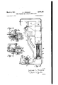
- Fig. l is an elevation of a screw driving machine, with parts broken away;
- Fig. 2 is a vertical elevation, partly in section, taken. at right angles to the showing of Fig. 1, but with the screw driver omitted;
- Fig. 3 is a vertical elevation, partly in section, of the driving device in operation
- Fig. 4 is a similar view, with the driver inoperative
- Fig. 5 is a transverse section on line 5--5 of Fig. 4;
- Figs. 6 and 7 are detailed sections of the transfer carrier
- Figs. 8 and 9 are details showing the operation of the hopper supply control
- Figs. 10 and 11 are diagrams of the wiring and the fluid supply lines.
- Fig. 12 is a detail of the elevator mechanism.
- a preferred form of my invention comprises a feed hopper 19 (Fig. 2) arranged to hold a supply of fasteners, such as nails, rivets or screws.
- the fasteners 12 are lifted from the hopper supply to a pair of inclined spaced rails 13 (Figs. 1 and 2) by means of vertically reciprocable elevator plates M.
- the fasteners are released serially from the rails 13 at required times and fed into a reciprocable carrier i5, which has a hole l6 therethrough adapted when in one end position to receive a fastener from the rails l3 and then to be moved to the other end position where it delivers the fastener to a duct or pipe ll through which compressed air is forced to transfer the fastener to the driving head 18 of the power driver.
- This power driver comprises a standard type of turbine or other pneumatic motor adapted to operate the driver, such as to rotate the screw driver I9 where the fastener to be driven is a screw.
- One feature of this construction comprises an automatic control of the fastener feeding mechanism which operates in a timed relation with the driver movement. Since the fastener is fed to a driving position by compressed air, it is preferred to employ fluid pressure mechanism to operate both the elevator I l that feeds the f-asteners to the rails and the transfer carrier I5 which holds the fastener and delivers it to the duct IT as needed.
- This fluid is likewise employed to operate the fastener driver, which is an air driven rotary turbine in the case of a screw driver.
- a vertically reciprocable piston 20 (Fig. 2) is employed to operate the elevator I l. The piston is urged towards a lower-most position by a compression spring 2
- the reciprocable carrier I5 is moved by fluid pressure and so is preferably formed as a piston (Figs. 6 and 7) mounted within a suitable cylinder 25 having a head 26 providing a pressure chamber between the piston and the cylinder walls. Air under pressure is fed to that chamber through the pipe 24, which receives air from a supply pipe 26 controlled by a solenoid valve 30.
- the righthand end portion of the carrier [5 makes a sliding fit with the cylinder wall 25 so that it serves as a piston to move the fastener carrying portion of the carrier; hence the piston serves the double function of a reciprocable carrier for the fastener and a fluid pressure actuated device for moving the carrier and its load.
- the piston I5 is urged towards the right-hand side of the chamber by a spring 32, which tends to hold the passage [6 in communication with the outlet delivery pipe I? that carries the fastener to the driving head 3.
- the piston l5 slidably fits within the cylindrical chamber 25 and when air pressure is applied, it will hold a fastener, such as the screw l2, until it is needed for delivery to the pipe ll.
- the spring 32 thrusts the piston towards the right and the screw drops into the pipe 11. At that time, a blast of air is driven through the passage I6 and pipe I! from a supply pipe line 35 which communicates with the main supply line 25 at all times, as shown in Fig. 2.
- the piston has an annular groove 35, which in the position of Fig. 7 communicates with ports in the cylinder wall 25 aligned with the pipes I! and 35, so that when the carrier l5 has returned to its left-hand position, a blast of air from pipe 35 will continue to plunger is urged outwardly by a compression spring 52 between the bottom of the head 18 and a shoulder on the plunger.
- the port 5! communicates with the passage in the head I8 when the tool is at rest, but driving pressure on the plunger causes it to move upwardly and close the port. It will be noted that the plunger carries the jaws 48 and forms a slidable extension of the head.
- the pressure serves first to push the plunger 50 into the outer casing l8 and to cut off the communication passage 5! from the pipe 41, so that if a fastener is thereafter delivered to the pipe, it will be held against the outer cylindrical wall of that plunger 50 until needed. It will also be noted that this relative upward movement of the plunger 50 cuts off the air passage from pipes ll and 4G and thus stops the air flow to the head, and causes the full air pressure to go through the pipe 44 to drive the motor turbine. When the plunger is in the rest position of Fig. 4, the air escapes downwardly through the driver head, and there is ordinarily not suificient pressure to rotate the drive the screw down the pipe I! and supply air to the turbine and driving head.
- the power driver for a screw may comprise a standard type of pneumatic turbine mounted in the casing 49 of the driver, and the shaft 4! is connected through standard clutch parts 42 with the rotatable screw driver [9 which is suitably l mounted in bearings in the driver casing.
- the turbine is connected through a flexible hose pipe 44 with a T coupling 45 (Fig. 4) which communicates always with the air pipe I! so that air is delivered under pressure to the turbine as required.
- the fastener passage in the pipe [1 opens into a pipe 46 which at its lower end communicates with a passage 41 in the side of the head I8, which delivers the fastener to its fmal driving position.
- the head is provided with a pair of spring pressed suitably pivoted jaws 48 arranged to grip the head of the fastener and hold it in place until the driver is forces it outwardly through the jaws.
- the head l8 comprises a cylindrical casing having the lateral air passage 31.
- the lower end of that passage 41 is normally closed, during operation of the driver, by a reciprocable hollow plunger which has a port 5i arranged to be brought into alignment with the passage 4! or to be shut off therefrom, so that the fastener l2 may be prevented from going to the driving head except at the proper time.
- the plunger 50 is suitably keyed to the outer casing i8 so that it may reciprocate.
- the turbine or driver casing 40 and the associated screw driving mechanism are carried on a slide bracket or body 55, which has two clamps 51 and 58 arranged to secure the casing in position.
- the bracket has two aligned cylindrical openings therethrough so arranged that the bracket may slide on the vertical tube 46.
- a compression spring 59 engages the bracket at its upper end, and its lower end rests on a stop member 60 that is threaded or otherwise secured on the pipe 46 in a fixed position.
- the spring holds the bracket and motor casing and associated screw driver parts in an uppermost position, until the device is employed to force a fastener into the work.
- the operator merely grips the bracket 56 and associated casing parts and thrusts the screw carried in the pivoted jaws 48 against the work, and as he pushes forward against the pressure of the spring 59, the bracket 55 moves down the pipe 46 after the plunger 50 has moved back to close off the air passage 41.
- the sliding movement of the bracket causes the driver I9 to engage the head of the screw and drive it into the work.
- the control of the pneumatically operated parts of the device is effected through the solenoid valve 30 which is interposed between the air pressure pipe line 26 and the pipes 23 and 24.
- This valve is controlled by a microswitch 66 (Figs. 3, 4 and 10) having a contact member 61 projecting outwardly into the path of a cam 68 that is mounted on the upper bracket arm 58 for movement therewith.
- This microswitch may be either the normally open or the normally closed type, with appropriate changes. In the form shown, it is a normally closed switch which is opened when the cam member 68 rides into contact with the projecting switch button Bl. Hence, the electric circuit is normally broken when the device is at rest, since the spring 59 holds the cam 68 against the switch button.
- the solenoid valve 38 which is controlled by that microswitch circuit may be of standard cona cylindrical casing it (Fig. 2) having a solenoid ii arranged around a movable iron core 12 that is adapted to be moved upwardly when the solenoid is energized.
- This core 12 is mounted loosely within a sleeve i3 adapted to permit the leakage of air past the core to an outlet pipe Hi.
- the inlet pipe 26 communicates with a vertical port it in the solenoid casing. That port is normally closed by a rubber stopper H on the bottom of the core, but when the core is lifted, then air may escape laterally to a passage connecting With the pipe line 24.
- the upper end of the core likewise has .a rubber stopper.
- the spring 32 will force the carrier iii to the right when the solenoid core moves down and connects the piston chamber with the outside atmosphere port 14 of the valve and so cuts oil" the air pressure from pipe 25.
- of the elevator mechanism will force the elevator piston Zil downwardly and lower the elevator [4. But when the driver is applied to the work and the inicroswitch 67: is released by the cam 68 moving downwardly away from it, this serves to make the electric circuit (see Fig.
- the carrier l5 lies normally in the screw delivering position of Fig. 6 when the driver is at rest.
- the solenoid is energized and the air flows to move the carrier IE to the left to pick up the next screw. It stays there until the screw previously delivered to the jaws 48 has been driven into the work and the operator lets up his pressure on the screw driver to move to a new location.
- This causes the bracket 56 and motor casing to move up the tube 46, and the cam 68 opens the microswitch circuit and deenergizes the solenoid and so releases the air pressure in pipe 2%.
- the spring 32 drives the carrier 15 to the right and delivers the screw therein to the tube ii and the air pressure from pipe 35 drive the screw all of the way to the driving head, since the port 5
- the hopper feed may be suitably constructed.
- the elevator comprises two parallel plates I4 spaced to slide vertically outside of and close to the parallel rails l3 on which the screws i2 are slidably carried by their heads. These plates are reciprocated vertically through a slot in the bottom of the hopper Hi. Their top edges 82 are beveled so that when they are pushed up through the mass of fasteners, one or more of the latter will be carried between the inwardly sloping beveled edges.
- These plates it slide close to the upper portions of the two parallel spaced carrier rails l3 and so deposit the fastener thereon.
- the rails l3 extend to the bottom of the hopper and project outwardly thereof.
- the elevator plates M are carried on or formed as continuations of the supporting slide members 84 which are secured to the top of the piston rod 83 that is moved upwardly by the piston 20.
- the screws are held on the carrier rails l3 and delivered one by one to the carrier i5 by means of a reciprocable device shown in Figs. 8 and 9.
- This comprises a guard 85 arranged to reciprocate across and close to the lower ends of the inclined rails l3.
- a knife edge 85 secured to the guard has a beveled edge on the opposite side of the rails arranged to move between two screws on the rails when the guard 85 moves to release the end screw. That is, when the guard 85 is moved from the guarding position of Fig. 9' to release the end fastener, the knife edge 86 will be interpositioned between that end fastener and the next one and so hold the rest of the fasteners on the rails while the lower one is released into the elongated space 8'!
- the driver I9 comes down into contact with the head of the screw to be driven, and this causes the clutch plates :12 to be engaged against the pressure of a compression spring that normally holds them apart, and the screw driver is thereby rotated in the required direction to thrust the screw into the work.
- a the bracket 56 moves down, it carries the cam 68 away from the microswitch button 51 and thus closes the electric circuit and the solenoid is energized with the result that the air pressure is admitted to move the elevator I4 up and to move the carrier I5 to the left to get another screw.
- the parts operate in the reverse directions and the cycle is completed. This reverse procedure happens quickly during the time that the operator is transferring the device to a new location for drivin the next screw. It will be understood that any suitable source of compressed air may be employed for operating the device.
- a single microswitch and one solenoid in a con-- trol circuit are suificient to govern the two motors, since only a single control valve in a single air line is required. That single air line serves for deliverin the fasteners to the work head as well as for operating the various motors.
- the hollow plunger 50 which is a slidable extension of the work head l8 carried by the stationary pipe 46, serves as a guiding sleeve for the driver I9 as well as a valve for the fastener air duct 47. This provides a simple form of valve for the air and a shut off for the fastener delivery tube. Hence, the device has the minimum of parts and it may be economically built and operated. Various other advantages inherent in this construction will be readily apparent.
- a fastener feeding and driving mechanism comprising a hollow work head having a fastener delivering air duct leading thereto, a hollow work engaging plunger having fastener carrying jaws and a port communicating with said duct, said plunger being slidable relative to the head when manually applied to a work piece and arranged to serve as a valve to close the duct, and power mechanism including a driver slidably movable within said head and plunger which releasably engages and drives the fastener held in the plunger jaws when the plunger is pressed against the work piece.
- a fastener feeding and driving mechanism comprising a hollow work head having a fastener delivering air duct leading thereto, means providing compressed air to drive a fastener through the duct, a hollow plunger slidably mounted relative to the head which has fastener holding jaws and a lateral port for admitting a fastener and air from the duct to the jaws, said plunger being movable as a valve to close the duct when pressed against a work piece, a fastener driver movable Within the work head to releasably engage and drive the fastener when the plunger is pressed against the work, a motor to operate said driver which is driven by air from said duct, and a compressed air supply tube communicating with said duct, so that the air escapes through the duct after delivering a fastener to the jaws until the plunger is manually pressed against the work and closes the duct passage and thus causes the full air pressure to be transmitted to the motor for operating the same.
- a fastener feeding and driving mechanism comprising a hollow fastener supporting head, a fastener delivering air duct communicating with the head, jaws carried by the head for supporting a, fastener delivered through the duct, a valve member associated with the jaws and slidably mounted within the head which is moved by pressure of the jaws against the work to close the duct passage to the head, means to hold the valve member normally retracted with the duct passage open when the head is at rest, a driver slidably movable within the head and arranged to contact and drive the fastener when the jaws are pressed towards the work, an air driven motor for the driver and a pipe line which continuously connects the motor with said air duct so that air pressure is transmitted to drive the motor when the valve member closes the duct outlet to the head.
- a fastener feeding and driving mechanism comprising a hollow work head for releasably supporting a fastener, a manually applied power operated driver which is moved longitudinally of and within the head for driving the fastener when the head is pressed against a work piece, a feed tube connected with the head for delivering a fastener thereto under pneumatic pressure, a fastener supply hopper, a fastener carrier which is movable between end positions for respectively receiving a fastener from the hopper and delivering it to the tube, selective mechanism for delivering a single fastener from the hopper to the carrier, resilient means to bias the carrier movement towards one end position, means including a duct having a valve therein for supplying fluid under pressure and moving the carrier to the other end position, and means for operating the valve and controlling the fiuid pressure movement of the carrier which is actuated in timed relation with the movement of the driver relative to the head.
- a device in which a spring moves the carrier to and normally holds 'it in a position where it may deliver a fastener to the tube and the valve controlling means is governed by the manual pressure of the head against a work piece so that the carrier is held by fiuid pressure in a fastener receiving position during the period of driving a fastener into the work.
- a device in which the carrier is normally spring held in position for delivering a fastener to the feed tube and is moved by air pressure to a, position for receiving a fastener from the hopper, and comprising a solenoid connected to move the valve and an electrical circuit including a switch controlled by movement of the driver relative to the head which causes the solenoid to operate the valve in a timed relation to the fastener driving operation.
- a fastener feeding and driving mechanism comprising a hollow driving head having jaws for releasably supporting a fastener in a driving position, a pneumatic duct for delivering a fastener to the head, a fastener supply hopper, a transfer carrier for selectively delivering a fastener to the duct, slide rails in the hopper for leading the fasteners serially to the transfer carrier, an elevator mechanism in the hop per movable vertically to feed fasteners to the rails, a spring pressed piston connected to the elevator which is resiliently held by the spring in an end position, a duct for admitting compressed air to move the piston to the opposite end position, a manually applied power operated driver for the fastener which is movable from an inoperative to an operative, position relative to the head for driving the fastener, and valve mechanism operated in timed relation with the movement of the driver for admitting air to move said piston.
- a fastener feeding and driving mechanism comprising a hollow work head having jaws for releasably holding a fastener, a manually applied, power operated driver which is movable within the head to a position of driving the fastener when the head is pressed against a work piece, a duct for leading a fastener to the head and jaws, a fastener supply hopper, means including a movable transfer carrier piston for receiving a single fastener from the hopper when in one position and delivering it to the duct when in another position, means including an air pressure duct having a valve therein for delivering compressed air and moving the piston to a fastener receiving position, a spring to return the carrier to a fastener delivering position, and an electrical circuit including a solenoid and a single switch controlled by movement of the driver relative to the head between rest and fastener driving positions, said valve being biased to a closed position when the driver is at rest and said switch being actuated and the solenoid energized to open the valve against the
Landscapes
- Engineering & Computer Science (AREA)
- Mechanical Engineering (AREA)
- Physics & Mathematics (AREA)
- Fluid Mechanics (AREA)
- Details Of Spanners, Wrenches, And Screw Drivers And Accessories (AREA)
Description
L. L. KRASNOW POWER-OPERATED SEMIAUTOMATIC SCREW DRIVER March 6, 1951 3 Sheets-Sheet 1 Filed me 5, 1948 Leonard L. Krasnow attorneg March 6, 1951 L. KRASNOW 2,544,165
POWEROPERATED SEMIAUTOMATIC SCREW DRIVER Filed June 5, 1948 s Sheets-Sheet 2 Leonard L. Krasnow Gttotneg March 6, 1951 Filed June 5, 1948 3 Sheets-Sheet 3 Ii 10 as 4 i! 50 3nvemor 52 ii 52 Leonard L. Krasnow BB is 48 2 31 L m.
Gttorneg Patented Mar. 6, 1951 UNITED STATES PATENT OFFICE POWER-OPERATED SEIVHAUTOMATIC SCREW DRIVER Massachusetts Application June 5, 1948, Serial No. 31,383
8 Claims. 1
This invention relates to a power driven, manually applied machine for delivering and driving fasteners semi-automatically, and particularly to a power operated, magazine fed, screw driver.
This invention comprises a construction in which a single air duct serves to supply compressed air for delivering a fastener from a transfer carrier to the jaws of a work head and for operating the motor of the fastener driver. The driver motor has its air supply controlled by a valve that is manually moved by the pressure of the head against the work. The transfer carrier receives a fastener from a hopper supply and holds it until needed and then delivers th fastener to the air duct in a timed relation with the movement of the driver to an inoperative position. The carrier and a hopper feed elevator are each operated by a pneumatic motor controlled by a valve in the air line that is electrically governed by a switch which is in turn cam actuated by movement of the fastener driver.
The primary object of the invention is to provide a simplified and economical construction which accomplishes the above ends.
Another object is to provide a device having pneumatically operated parts which ar electrically controlled by a single switch mechanism actuated according to the manua1 application of the device for driving a fastener.
A further object is to provide a device in which the operating motors are held under spring pressure in desired end positions and are moved by air pressure to the opposite end positions in a timed relation with the operation of driving the fastener.
A further object is to employ a single pneumatic conduit for feeding a fastener to the work head and for Supplying air under pressure to a motor which operates the fastener driver and wherein the air supply to the motoris controlled by a valve in the work head that is operated by the manual application of the head to the work p1ece.
A still further object is to employ substantially the full air pressure to deliver the fastener to the work head and then to divert that pressure from the head to drive the motor and at the same time to close the feed duct at the work head and prevent the passage of a second fastener to the head while another is being driven into the work. Other objects will be apparent in the following disclosure. 1
Referring to the drawings which illustrate a preferred embodiment of the invention adapted for driving a screw into a work piece:
Fig. l is an elevation of a screw driving machine, with parts broken away;
Fig. 2 is a vertical elevation, partly in section, taken. at right angles to the showing of Fig. 1, but with the screw driver omitted;
Fig. 3 is a vertical elevation, partly in section, of the driving device in operation;
Fig. 4 is a similar view, with the driver inoperative;
Fig. 5 is a transverse section on line 5--5 of Fig. 4;
Figs. 6 and 7 are detailed sections of the transfer carrier;
Figs. 8 and 9 are details showing the operation of the hopper supply control;
Figs. 10 and 11 are diagrams of the wiring and the fluid supply lines; and
Fig. 12 is a detail of the elevator mechanism.
A preferred form of my invention comprises a feed hopper 19 (Fig. 2) arranged to hold a supply of fasteners, such as nails, rivets or screws. The fasteners 12 are lifted from the hopper supply to a pair of inclined spaced rails 13 (Figs. 1 and 2) by means of vertically reciprocable elevator plates M. The fasteners are released serially from the rails 13 at required times and fed into a reciprocable carrier i5, which has a hole l6 therethrough adapted when in one end position to receive a fastener from the rails l3 and then to be moved to the other end position where it delivers the fastener to a duct or pipe ll through which compressed air is forced to transfer the fastener to the driving head 18 of the power driver. This power driver comprises a standard type of turbine or other pneumatic motor adapted to operate the driver, such as to rotate the screw driver I9 where the fastener to be driven is a screw.
One feature of this construction comprises an automatic control of the fastener feeding mechanism which operates in a timed relation with the driver movement. Since the fastener is fed to a driving position by compressed air, it is preferred to employ fluid pressure mechanism to operate both the elevator I l that feeds the f-asteners to the rails and the transfer carrier I5 which holds the fastener and delivers it to the duct IT as needed. This fluid is likewise employed to operate the fastener driver, which is an air driven rotary turbine in the case of a screw driver. To that end, a vertically reciprocable piston 20 (Fig. 2) is employed to operate the elevator I l. The piston is urged towards a lower-most position by a compression spring 2| suitably mounted in the piston casing 22. Air
The reciprocable carrier I5 is moved by fluid pressure and so is preferably formed as a piston (Figs. 6 and 7) mounted within a suitable cylinder 25 having a head 26 providing a pressure chamber between the piston and the cylinder walls. Air under pressure is fed to that chamber through the pipe 24, which receives air from a supply pipe 26 controlled by a solenoid valve 30. The righthand end portion of the carrier [5 makes a sliding fit with the cylinder wall 25 so that it serves as a piston to move the fastener carrying portion of the carrier; hence the piston serves the double function of a reciprocable carrier for the fastener and a fluid pressure actuated device for moving the carrier and its load. The piston I5 is urged towards the right-hand side of the chamber by a spring 32, which tends to hold the passage [6 in communication with the outlet delivery pipe I? that carries the fastener to the driving head 3. As shown in Fig. 7, the piston l5 slidably fits within the cylindrical chamber 25 and when air pressure is applied, it will hold a fastener, such as the screw l2, until it is needed for delivery to the pipe ll. When the air pressure in the pipe 24 is released, then the spring 32 thrusts the piston towards the right and the screw drops into the pipe 11. At that time, a blast of air is driven through the passage I6 and pipe I! from a supply pipe line 35 which communicates with the main supply line 25 at all times, as shown in Fig. 2. The piston has an annular groove 35, which in the position of Fig. 7 communicates with ports in the cylinder wall 25 aligned with the pipes I! and 35, so that when the carrier l5 has returned to its left-hand position, a blast of air from pipe 35 will continue to plunger is urged outwardly by a compression spring 52 between the bottom of the head 18 and a shoulder on the plunger. The port 5! communicates with the passage in the head I8 when the tool is at rest, but driving pressure on the plunger causes it to move upwardly and close the port. It will be noted that the plunger carries the jaws 48 and forms a slidable extension of the head. When the device is manually applied to force the fastener into the work, the pressure serves first to push the plunger 50 into the outer casing l8 and to cut off the communication passage 5! from the pipe 41, so that if a fastener is thereafter delivered to the pipe, it will be held against the outer cylindrical wall of that plunger 50 until needed. It will also be noted that this relative upward movement of the plunger 50 cuts off the air passage from pipes ll and 4G and thus stops the air flow to the head, and causes the full air pressure to go through the pipe 44 to drive the motor turbine. When the plunger is in the rest position of Fig. 4, the air escapes downwardly through the driver head, and there is ordinarily not suificient pressure to rotate the drive the screw down the pipe I! and supply air to the turbine and driving head.
The power driver for a screw may comprise a standard type of pneumatic turbine mounted in the casing 49 of the driver, and the shaft 4! is connected through standard clutch parts 42 with the rotatable screw driver [9 which is suitably l mounted in bearings in the driver casing. The turbine is connected through a flexible hose pipe 44 with a T coupling 45 (Fig. 4) which communicates always with the air pipe I! so that air is delivered under pressure to the turbine as required. The fastener passage in the pipe [1 opens into a pipe 46 which at its lower end communicates with a passage 41 in the side of the head I8, which delivers the fastener to its fmal driving position. The head is provided with a pair of spring pressed suitably pivoted jaws 48 arranged to grip the head of the fastener and hold it in place until the driver is forces it outwardly through the jaws.
As shown in Figs. 3 and 4, the head l8 comprises a cylindrical casing having the lateral air passage 31. The lower end of that passage 41 is normally closed, during operation of the driver, by a reciprocable hollow plunger which has a port 5i arranged to be brought into alignment with the passage 4! or to be shut off therefrom, so that the fastener l2 may be prevented from going to the driving head except at the proper time. The plunger 50 is suitably keyed to the outer casing i8 so that it may reciprocate. The
turbine. This forms a very simple control valve for the turbine, as well as serving to deliver a fastener to the driving head when needed. Hence, no further trigger or valve mechanism is required to turn on and off the motor, since this is controlled fully by the application of the driver to the work.
The turbine or driver casing 40 and the associated screw driving mechanism are carried on a slide bracket or body 55, which has two clamps 51 and 58 arranged to secure the casing in position. The bracket has two aligned cylindrical openings therethrough so arranged that the bracket may slide on the vertical tube 46. A compression spring 59 engages the bracket at its upper end, and its lower end rests on a stop member 60 that is threaded or otherwise secured on the pipe 46 in a fixed position. Thus, the spring holds the bracket and motor casing and associated screw driver parts in an uppermost position, until the device is employed to force a fastener into the work. For that purpose, the operator merely grips the bracket 56 and associated casing parts and thrusts the screw carried in the pivoted jaws 48 against the work, and as he pushes forward against the pressure of the spring 59, the bracket 55 moves down the pipe 46 after the plunger 50 has moved back to close off the air passage 41. The sliding movement of the bracket causes the driver I9 to engage the head of the screw and drive it into the work.
The control of the pneumatically operated parts of the device is effected through the solenoid valve 30 which is interposed between the air pressure pipe line 26 and the pipes 23 and 24. This valve is controlled by a microswitch 66 (Figs. 3, 4 and 10) having a contact member 61 projecting outwardly into the path of a cam 68 that is mounted on the upper bracket arm 58 for movement therewith. This microswitch may be either the normally open or the normally closed type, with appropriate changes. In the form shown, it is a normally closed switch which is opened when the cam member 68 rides into contact with the projecting switch button Bl. Hence, the electric circuit is normally broken when the device is at rest, since the spring 59 holds the cam 68 against the switch button.
The solenoid valve 38 which is controlled by that microswitch circuit may be of standard cona cylindrical casing it (Fig. 2) having a solenoid ii arranged around a movable iron core 12 that is adapted to be moved upwardly when the solenoid is energized. This core 12 is mounted loosely within a sleeve i3 adapted to permit the leakage of air past the core to an outlet pipe Hi. The inlet pipe 26 communicates with a vertical port it in the solenoid casing. That port is normally closed by a rubber stopper H on the bottom of the core, but when the core is lifted, then air may escape laterally to a passage connecting With the pipe line 24. The upper end of the core likewise has .a rubber stopper. 18 that closes oil th vertical exhaust passage 14 when the core is in its uppermost position. That is, when the solenoid is activated, the plunger moves up and closes the outlet M, and the line 24 carries air to the various operating parts. When the solenoid is de-energized, the core falls by gravity or under the pressure of a spring, and the air that had been applied under pressure to the other mechanism parts is now allowed to escape to the atmosphere through port it. At that time the springs of the plungers l5 and 20 operate to move them to their inactive end positions.
Referring now to Figs. 6 and '7, the spring 32 will force the carrier iii to the right when the solenoid core moves down and connects the piston chamber with the outside atmosphere port 14 of the valve and so cuts oil" the air pressure from pipe 25. At the same time, the spring 2| of the elevator mechanism will force the elevator piston Zil downwardly and lower the elevator [4. But when the driver is applied to the work and the inicroswitch 67: is released by the cam 68 moving downwardly away from it, this serves to make the electric circuit (see Fig. 10) and then the solenoid is energized and the core 12 is lifted to close the exhaust passage port 14 and permit the air under pressure to pass through the valve from the pipe 2e to the connecting pipes 2 1 and 23, and so move the elevator upwardly and at the same time force the carrier piston I5 to the left (Fig. 7) where it will receive another screw.
As above described, the carrier l5 lies normally in the screw delivering position of Fig. 6 when the driver is at rest. When the driver is applied to the work, the solenoid is energized and the air flows to move the carrier IE to the left to pick up the next screw. It stays there until the screw previously delivered to the jaws 48 has been driven into the work and the operator lets up his pressure on the screw driver to move to a new location. This causes the bracket 56 and motor casing to move up the tube 46, and the cam 68 opens the microswitch circuit and deenergizes the solenoid and so releases the air pressure in pipe 2%. Then the spring 32 drives the carrier 15 to the right and delivers the screw therein to the tube ii and the air pressure from pipe 35 drive the screw all of the way to the driving head, since the port 5| is open. This takes place in a small unit of time. If the tube ll is very long, the timing can be arranged to transfer a screw to the tube as desired, it being noted that the retracted valve plunger 50 will prevent a second screw from being delivered to the head while one is being driven into th work. Since the microswitch is normally open and the solenoid is not energized when the driver is at rest, the air pressure is released from the piston l5, and the carrier I5 is held at a screw delivering position during the inoperative or rest period. The structure may be such that air pressure is admitted to the carrier 15 either when the driver 6 is rotating the screw or when it is at rest, and the various parts are appropriately arranged.
The hopper feed may be suitably constructed. As shown in Figs. 1, 2 and 12, the elevator comprises two parallel plates I4 spaced to slide vertically outside of and close to the parallel rails l3 on which the screws i2 are slidably carried by their heads. These plates are reciprocated vertically through a slot in the bottom of the hopper Hi. Their top edges 82 are beveled so that when they are pushed up through the mass of fasteners, one or more of the latter will be carried between the inwardly sloping beveled edges. These plates it slide close to the upper portions of the two parallel spaced carrier rails l3 and so deposit the fastener thereon. The rails l3 extend to the bottom of the hopper and project outwardly thereof. They are so positioned that the screws hang downwardly by their heads between the rails and slide to a point of delivery. The elevator plates M are carried on or formed as continuations of the supporting slide members 84 which are secured to the top of the piston rod 83 that is moved upwardly by the piston 20.
The screws are held on the carrier rails l3 and delivered one by one to the carrier i5 by means of a reciprocable device shown in Figs. 8 and 9. This comprises a guard 85 arranged to reciprocate across and close to the lower ends of the inclined rails l3. A knife edge 85 secured to the guard has a beveled edge on the opposite side of the rails arranged to move between two screws on the rails when the guard 85 moves to release the end screw. That is, when the guard 85 is moved from the guarding position of Fig. 9' to release the end fastener, the knife edge 86 will be interpositioned between that end fastener and the next one and so hold the rest of the fasteners on the rails while the lower one is released into the elongated space 8'! formed between the parts 35 and 88. This space communicates at all times with the top open end of a short delivery tube or curved plate 88 which directs the released screw into a hole in the top of the piston casing 25 which is closed by the piston [5 in the position of Fig. 6 but which opens into the compartment i6 of the piston when the latter is moved to the position of Fig. '7. The guard members 85 and 86 (Fig. 6) are mounted on a vertical standard 89 carried on the piston rod 90 which is fixed to the piston I5 and reciprocates through an opening in the lefthand wall 9| of the screw carrier casing. Thus, the guard and knife edge move only as the piston I5 moves. Hence, only one fastener is delivered to the carrier I5 when air pressure is admitted to reciprocate the carrier to its lefthand position of Fig. 7. This happens when the driver is driving a screw into the work; so that the screw in the carrier is ready for discharge into tube ll the instant that the operator lets up his pressure on the driver.
In the construction illustrated, the air flows steadily through pipe 35 to pipe ll when the piston carrier i5 is at the right (Fig. 6) and this insures that sufiicient air is supplied to move the fastener all of the way to the driving head. At that time when the device is at rest, the driving head is in the position of Fig. with the valve 5! open. The microswitch circuit is held open by the cam 68 and the solenoid core '52 is in its lowermost position, closing off the air from access to the piston chambers of the elevator and screw carrier. The pipe line 24 (Fig. 2) is connected through the solenoid valve with the outside air pipe I4, and there is no back pressure to interfere with the action of the two springs which position the screw carrier I at the right and hold the elevator plates I 4 in their lowermost positions. When the operator applies the driver to the work to drive another screw into position, the first stage of the applied pressure causes, the plunger 50 to move upwardly and close off the air passage 5i. This forces all of the air through pipe 44 to the turbine and rotates it. Then, as the operator pushes the screw driver further forward, the driver I9 comes down into contact with the head of the screw to be driven, and this causes the clutch plates :12 to be engaged against the pressure of a compression spring that normally holds them apart, and the screw driver is thereby rotated in the required direction to thrust the screw into the work. A the bracket 56 moves down, it carries the cam 68 away from the microswitch button 51 and thus closes the electric circuit and the solenoid is energized with the result that the air pressure is admitted to move the elevator I4 up and to move the carrier I5 to the left to get another screw. When the operator releases his pressure on the screw driver, the parts operate in the reverse directions and the cycle is completed. This reverse procedure happens quickly during the time that the operator is transferring the device to a new location for drivin the next screw. It will be understood that any suitable source of compressed air may be employed for operating the device.
The construction as described is simple be cause the reciprocable spring pressed transfer carrier and the elevator motor are moved by air only in one direction; hence slide valves are not needed to operate the motor pistons. Also,
a single microswitch and one solenoid in a con-- trol circuit are suificient to govern the two motors, since only a single control valve in a single air line is required. That single air line serves for deliverin the fasteners to the work head as well as for operating the various motors. The hollow plunger 50, which is a slidable extension of the work head l8 carried by the stationary pipe 46, serves as a guiding sleeve for the driver I9 as well as a valve for the fastener air duct 47. This provides a simple form of valve for the air and a shut off for the fastener delivery tube. Hence, the device has the minimum of parts and it may be economically built and operated. Various other advantages inherent in this construction will be readily apparent.
It will be appreciated that various modifications may be made in this construction within the knowledge of one skilled in the art in view of the above disclosure and that the drawings and description are to be interpreted as illustrating the preferred embodiment and not as imposing limitations on theclaims appended hereto.
I claim:
1. A fastener feeding and driving mechanism comprising a hollow work head having a fastener delivering air duct leading thereto, a hollow work engaging plunger having fastener carrying jaws and a port communicating with said duct, said plunger being slidable relative to the head when manually applied to a work piece and arranged to serve as a valve to close the duct, and power mechanism including a driver slidably movable within said head and plunger which releasably engages and drives the fastener held in the plunger jaws when the plunger is pressed against the work piece.
2. A fastener feeding and driving mechanism comprising a hollow work head having a fastener delivering air duct leading thereto, means providing compressed air to drive a fastener through the duct, a hollow plunger slidably mounted relative to the head which has fastener holding jaws and a lateral port for admitting a fastener and air from the duct to the jaws, said plunger being movable as a valve to close the duct when pressed against a work piece, a fastener driver movable Within the work head to releasably engage and drive the fastener when the plunger is pressed against the work, a motor to operate said driver which is driven by air from said duct, and a compressed air supply tube communicating with said duct, so that the air escapes through the duct after delivering a fastener to the jaws until the plunger is manually pressed against the work and closes the duct passage and thus causes the full air pressure to be transmitted to the motor for operating the same.
3. A fastener feeding and driving mechanism comprising a hollow fastener supporting head, a fastener delivering air duct communicating with the head, jaws carried by the head for supporting a, fastener delivered through the duct, a valve member associated with the jaws and slidably mounted within the head which is moved by pressure of the jaws against the work to close the duct passage to the head, means to hold the valve member normally retracted with the duct passage open when the head is at rest, a driver slidably movable within the head and arranged to contact and drive the fastener when the jaws are pressed towards the work, an air driven motor for the driver and a pipe line which continuously connects the motor with said air duct so that air pressure is transmitted to drive the motor when the valve member closes the duct outlet to the head.
4. A fastener feeding and driving mechanism comprising a hollow work head for releasably supporting a fastener, a manually applied power operated driver which is moved longitudinally of and within the head for driving the fastener when the head is pressed against a work piece, a feed tube connected with the head for delivering a fastener thereto under pneumatic pressure, a fastener supply hopper, a fastener carrier which is movable between end positions for respectively receiving a fastener from the hopper and delivering it to the tube, selective mechanism for delivering a single fastener from the hopper to the carrier, resilient means to bias the carrier movement towards one end position, means including a duct having a valve therein for supplying fluid under pressure and moving the carrier to the other end position, and means for operating the valve and controlling the fiuid pressure movement of the carrier which is actuated in timed relation with the movement of the driver relative to the head.
5. A device according to claim 4 in which a spring moves the carrier to and normally holds 'it in a position where it may deliver a fastener to the tube and the valve controlling means is governed by the manual pressure of the head against a work piece so that the carrier is held by fiuid pressure in a fastener receiving position during the period of driving a fastener into the work.
6. A device according to claim 4 in which the carrier is normally spring held in position for delivering a fastener to the feed tube and is moved by air pressure to a, position for receiving a fastener from the hopper, and comprising a solenoid connected to move the valve and an electrical circuit including a switch controlled by movement of the driver relative to the head which causes the solenoid to operate the valve in a timed relation to the fastener driving operation.
7. A fastener feeding and driving mechanism comprising a hollow driving head having jaws for releasably supporting a fastener in a driving position, a pneumatic duct for delivering a fastener to the head, a fastener supply hopper, a transfer carrier for selectively delivering a fastener to the duct, slide rails in the hopper for leading the fasteners serially to the transfer carrier, an elevator mechanism in the hop per movable vertically to feed fasteners to the rails, a spring pressed piston connected to the elevator which is resiliently held by the spring in an end position, a duct for admitting compressed air to move the piston to the opposite end position, a manually applied power operated driver for the fastener which is movable from an inoperative to an operative, position relative to the head for driving the fastener, and valve mechanism operated in timed relation with the movement of the driver for admitting air to move said piston.
8. A fastener feeding and driving mechanism comprising a hollow work head having jaws for releasably holding a fastener, a manually applied, power operated driver which is movable within the head to a position of driving the fastener when the head is pressed against a work piece, a duct for leading a fastener to the head and jaws, a fastener supply hopper, means including a movable transfer carrier piston for receiving a single fastener from the hopper when in one position and delivering it to the duct when in another position, means including an air pressure duct having a valve therein for delivering compressed air and moving the piston to a fastener receiving position, a spring to return the carrier to a fastener delivering position, and an electrical circuit including a solenoid and a single switch controlled by movement of the driver relative to the head between rest and fastener driving positions, said valve being biased to a closed position when the driver is at rest and said switch being actuated and the solenoid energized to open the valve against the bias to admit air to said duct and move the carrier when the head is pressed against the work.
LEONARD 'L. KRASNOW.
REFERENCES oITEn The following references are of record in the file of this patent:
UNITED STATES PATENTS Number Name Date 950,534 Hunt Mar. 1, 1910 1,499,887 Snyder et a1 July 1, 1924 1,703,458 Ruff Feb. 26, 1929 1,813,697 Dellaree July 7, 1931 1,921,485 Seger Aug. 8, 1933 1,980,967 DeMooy Nov. 13, 1934 2,266,302 Blair Dec. 16, 1941 2,373,992 Billinghurst Apr. 17, 1945
Priority Applications (1)
| Application Number | Priority Date | Filing Date | Title |
|---|---|---|---|
| US31383A US2544165A (en) | 1948-06-05 | 1948-06-05 | Power-operated semiautomatic screw driver |
Applications Claiming Priority (1)
| Application Number | Priority Date | Filing Date | Title |
|---|---|---|---|
| US31383A US2544165A (en) | 1948-06-05 | 1948-06-05 | Power-operated semiautomatic screw driver |
Publications (1)
| Publication Number | Publication Date |
|---|---|
| US2544165A true US2544165A (en) | 1951-03-06 |
Family
ID=21859138
Family Applications (1)
| Application Number | Title | Priority Date | Filing Date |
|---|---|---|---|
| US31383A Expired - Lifetime US2544165A (en) | 1948-06-05 | 1948-06-05 | Power-operated semiautomatic screw driver |
Country Status (1)
| Country | Link |
|---|---|
| US (1) | US2544165A (en) |
Cited By (36)
| Publication number | Priority date | Publication date | Assignee | Title |
|---|---|---|---|---|
| US2596958A (en) * | 1948-09-01 | 1952-05-13 | Chatsworth Mfg Co | Machine for feeding and inserting screws |
| US2670770A (en) * | 1950-07-27 | 1954-03-02 | Du Mont Allen B Lab Inc | Screw holding and feeding means for power-operated screw drivers |
| US2706504A (en) * | 1952-09-04 | 1955-04-19 | Frank Manton | Power operated screwdriver with screw delivering means |
| US2754860A (en) * | 1954-06-23 | 1956-07-17 | Taymouth Ind Ltd | Fastener feeding and driving mechanism |
| US2770269A (en) * | 1951-01-12 | 1956-11-13 | Illinois Tool Works | Power screw driver |
| US2772426A (en) * | 1953-01-21 | 1956-12-04 | Detroit Power Screwdriver Comp | Device for inserting headed members in apertured members |
| US2803274A (en) * | 1956-05-31 | 1957-08-20 | Gen Electric | Power-operated fastener dispensing and driving means |
| US2818893A (en) * | 1956-05-31 | 1958-01-07 | Aro Equipment Corp | Power operated magazine fed screw driver |
| US2886076A (en) * | 1958-03-11 | 1959-05-12 | Gen Am Transport | Fastener feeding and driving machines |
| US2904084A (en) * | 1958-03-31 | 1959-09-15 | Rogan Bros | Power-operated screw feed and drive mechanism |
| US2943652A (en) * | 1955-12-06 | 1960-07-05 | Gen Motors Corp | Power operated tool for feeding and driving headed fasteners |
| US2951516A (en) * | 1958-07-09 | 1960-09-06 | Gen Motors Corp | Fastener driving tool with hopper and feed means |
| US3038637A (en) * | 1958-09-23 | 1962-06-12 | Pneuma Serve Ltd | Feeding apparatus for fasteners and the like |
| DE1149310B (en) * | 1954-05-04 | 1963-05-22 | United Shoe Machinery Corp | Screwing device |
| DE1174270B (en) * | 1956-04-16 | 1964-07-16 | United Shoe Machinery Corp | Nailing device |
| US3247874A (en) * | 1961-11-27 | 1966-04-26 | Tru Tork Inc | Power operated screw driver and feeding mechanism |
| US3268115A (en) * | 1964-07-15 | 1966-08-23 | Lamb Co F Jos | Workpiece escapement for runways |
| US3275191A (en) * | 1965-06-29 | 1966-09-27 | Tru Tork Inc | Article-feed apparatus having an article transfer means and fluid means to propel articles through a tube |
| US3297199A (en) * | 1965-08-30 | 1967-01-10 | Ingersoll Rand Co | Fastener escapement including a discharge assistant means |
| US3311262A (en) * | 1965-07-19 | 1967-03-28 | Trn Tork Inc | Plural transversely acting controllers for releasing articles |
| DE1269067B (en) * | 1955-07-20 | 1968-05-22 | Reich Maschf Gmbh Karl | Device for feeding nails to a nail driving machine |
| DE1277768B (en) * | 1963-06-13 | 1968-09-12 | Langendorf Watch Co | Device for screwing in screws |
| US3516574A (en) * | 1967-11-20 | 1970-06-23 | Reich Maschf Gmbh Karl | Nail selecting and feeding mechanism for nailing apparatus |
| US3623637A (en) * | 1969-12-29 | 1971-11-30 | Teletype Corp | Vacuum chuck and methods of transferring workpieces |
| US3883040A (en) * | 1970-11-14 | 1975-05-13 | Peter Martin Bell | Pneumatically operable gating mechanism |
| US4002265A (en) * | 1974-10-25 | 1977-01-11 | Babette Dixon, Trustee of a trust identified as Paul H. Dixon Trust | Apparatus for pneumatically delivering parts |
| US4208153A (en) * | 1977-12-23 | 1980-06-17 | The Boeing Company | Apparatus for dispensing rivets and similar articles |
| US4363573A (en) * | 1980-10-30 | 1982-12-14 | Clyde Corporation | Article feeding apparatus |
| US4495841A (en) * | 1982-04-21 | 1985-01-29 | Matsushita Electric Industrial Co., Ltd. | Automatic screwdriver |
| US4627316A (en) * | 1982-04-21 | 1986-12-09 | Matsushita Electric Industrial Co., Ltd. | Automatic screwdriver |
| US5360137A (en) * | 1992-07-17 | 1994-11-01 | Yugenkaisha Shinjo Seisakusho | Row feeder for distributing nuts |
| CN101947761A (en) * | 2010-09-20 | 2011-01-19 | 李光辉 | Multifunctional fully-automatic screw conveyer |
| US20110158754A1 (en) * | 2009-12-29 | 2011-06-30 | Fu Tai Hua Industry (Shenzhen) Co., Ltd. | Automatic material feeder |
| CN102152958A (en) * | 2010-02-12 | 2011-08-17 | 株式会社大武源工业 | Automatic screw tightening apparatus |
| US8015686B2 (en) | 2005-08-31 | 2011-09-13 | Newfrey Llc | Method and device for supply of connecting elements to a processing apparatus |
| DE102007042876B4 (en) * | 2007-09-08 | 2021-06-02 | Bayerische Motoren Werke Aktiengesellschaft | Device for separating fastening elements |
Citations (8)
| Publication number | Priority date | Publication date | Assignee | Title |
|---|---|---|---|---|
| US950534A (en) * | 1906-03-30 | 1910-03-01 | G D Reynolds & Company | Screw-driving machine. |
| US1499887A (en) * | 1919-08-25 | 1924-07-01 | Reynolds Machine Company | Screw-driving machine |
| US1703458A (en) * | 1926-12-31 | 1929-02-26 | Alonzo W Ruff | Nail-driving apparatus |
| US1813697A (en) * | 1926-01-09 | 1931-07-07 | Roy W Bailey | Screw feeding mechanism |
| US1921485A (en) * | 1930-09-18 | 1933-08-08 | Hudson Motor Car Co | Feeder for portable tools |
| US1980967A (en) * | 1930-11-22 | 1934-11-13 | Cleveland Pneumatic Tool Co | Nail driving device |
| US2266302A (en) * | 1939-05-08 | 1941-12-16 | Blair Walter | Power driven portable tool |
| US2373992A (en) * | 1943-06-18 | 1945-04-17 | Charles Handler | Self-feeding power-driven screw driver or like tool |
-
1948
- 1948-06-05 US US31383A patent/US2544165A/en not_active Expired - Lifetime
Patent Citations (8)
| Publication number | Priority date | Publication date | Assignee | Title |
|---|---|---|---|---|
| US950534A (en) * | 1906-03-30 | 1910-03-01 | G D Reynolds & Company | Screw-driving machine. |
| US1499887A (en) * | 1919-08-25 | 1924-07-01 | Reynolds Machine Company | Screw-driving machine |
| US1813697A (en) * | 1926-01-09 | 1931-07-07 | Roy W Bailey | Screw feeding mechanism |
| US1703458A (en) * | 1926-12-31 | 1929-02-26 | Alonzo W Ruff | Nail-driving apparatus |
| US1921485A (en) * | 1930-09-18 | 1933-08-08 | Hudson Motor Car Co | Feeder for portable tools |
| US1980967A (en) * | 1930-11-22 | 1934-11-13 | Cleveland Pneumatic Tool Co | Nail driving device |
| US2266302A (en) * | 1939-05-08 | 1941-12-16 | Blair Walter | Power driven portable tool |
| US2373992A (en) * | 1943-06-18 | 1945-04-17 | Charles Handler | Self-feeding power-driven screw driver or like tool |
Cited By (40)
| Publication number | Priority date | Publication date | Assignee | Title |
|---|---|---|---|---|
| US2596958A (en) * | 1948-09-01 | 1952-05-13 | Chatsworth Mfg Co | Machine for feeding and inserting screws |
| US2670770A (en) * | 1950-07-27 | 1954-03-02 | Du Mont Allen B Lab Inc | Screw holding and feeding means for power-operated screw drivers |
| US2770269A (en) * | 1951-01-12 | 1956-11-13 | Illinois Tool Works | Power screw driver |
| US2706504A (en) * | 1952-09-04 | 1955-04-19 | Frank Manton | Power operated screwdriver with screw delivering means |
| US2772426A (en) * | 1953-01-21 | 1956-12-04 | Detroit Power Screwdriver Comp | Device for inserting headed members in apertured members |
| DE1149310B (en) * | 1954-05-04 | 1963-05-22 | United Shoe Machinery Corp | Screwing device |
| US2754860A (en) * | 1954-06-23 | 1956-07-17 | Taymouth Ind Ltd | Fastener feeding and driving mechanism |
| DE1269067B (en) * | 1955-07-20 | 1968-05-22 | Reich Maschf Gmbh Karl | Device for feeding nails to a nail driving machine |
| US2943652A (en) * | 1955-12-06 | 1960-07-05 | Gen Motors Corp | Power operated tool for feeding and driving headed fasteners |
| DE1174270B (en) * | 1956-04-16 | 1964-07-16 | United Shoe Machinery Corp | Nailing device |
| DE1177088B (en) * | 1956-04-16 | 1964-08-27 | United Shoe Machinery Corp | Nail conveyor |
| US2818893A (en) * | 1956-05-31 | 1958-01-07 | Aro Equipment Corp | Power operated magazine fed screw driver |
| US2803274A (en) * | 1956-05-31 | 1957-08-20 | Gen Electric | Power-operated fastener dispensing and driving means |
| US2886076A (en) * | 1958-03-11 | 1959-05-12 | Gen Am Transport | Fastener feeding and driving machines |
| US2904084A (en) * | 1958-03-31 | 1959-09-15 | Rogan Bros | Power-operated screw feed and drive mechanism |
| US2951516A (en) * | 1958-07-09 | 1960-09-06 | Gen Motors Corp | Fastener driving tool with hopper and feed means |
| US3038637A (en) * | 1958-09-23 | 1962-06-12 | Pneuma Serve Ltd | Feeding apparatus for fasteners and the like |
| US3247874A (en) * | 1961-11-27 | 1966-04-26 | Tru Tork Inc | Power operated screw driver and feeding mechanism |
| DE1277768B (en) * | 1963-06-13 | 1968-09-12 | Langendorf Watch Co | Device for screwing in screws |
| US3268115A (en) * | 1964-07-15 | 1966-08-23 | Lamb Co F Jos | Workpiece escapement for runways |
| US3275191A (en) * | 1965-06-29 | 1966-09-27 | Tru Tork Inc | Article-feed apparatus having an article transfer means and fluid means to propel articles through a tube |
| US3311262A (en) * | 1965-07-19 | 1967-03-28 | Trn Tork Inc | Plural transversely acting controllers for releasing articles |
| US3297199A (en) * | 1965-08-30 | 1967-01-10 | Ingersoll Rand Co | Fastener escapement including a discharge assistant means |
| US3516574A (en) * | 1967-11-20 | 1970-06-23 | Reich Maschf Gmbh Karl | Nail selecting and feeding mechanism for nailing apparatus |
| US3623637A (en) * | 1969-12-29 | 1971-11-30 | Teletype Corp | Vacuum chuck and methods of transferring workpieces |
| US3883040A (en) * | 1970-11-14 | 1975-05-13 | Peter Martin Bell | Pneumatically operable gating mechanism |
| US4002265A (en) * | 1974-10-25 | 1977-01-11 | Babette Dixon, Trustee of a trust identified as Paul H. Dixon Trust | Apparatus for pneumatically delivering parts |
| US4208153A (en) * | 1977-12-23 | 1980-06-17 | The Boeing Company | Apparatus for dispensing rivets and similar articles |
| US4363573A (en) * | 1980-10-30 | 1982-12-14 | Clyde Corporation | Article feeding apparatus |
| US4627316A (en) * | 1982-04-21 | 1986-12-09 | Matsushita Electric Industrial Co., Ltd. | Automatic screwdriver |
| US4495841A (en) * | 1982-04-21 | 1985-01-29 | Matsushita Electric Industrial Co., Ltd. | Automatic screwdriver |
| US5360137A (en) * | 1992-07-17 | 1994-11-01 | Yugenkaisha Shinjo Seisakusho | Row feeder for distributing nuts |
| US8015686B2 (en) | 2005-08-31 | 2011-09-13 | Newfrey Llc | Method and device for supply of connecting elements to a processing apparatus |
| US8973247B2 (en) | 2005-08-31 | 2015-03-10 | Newfrey Llc | Method and device for supply of connecting elements to a processing apparatus |
| DE102007042876B4 (en) * | 2007-09-08 | 2021-06-02 | Bayerische Motoren Werke Aktiengesellschaft | Device for separating fastening elements |
| US20110158754A1 (en) * | 2009-12-29 | 2011-06-30 | Fu Tai Hua Industry (Shenzhen) Co., Ltd. | Automatic material feeder |
| CN102152958A (en) * | 2010-02-12 | 2011-08-17 | 株式会社大武源工业 | Automatic screw tightening apparatus |
| CN102152958B (en) * | 2010-02-12 | 2013-11-13 | 株式会社大武源工业 | Automatic screw tightening apparatus |
| CN101947761A (en) * | 2010-09-20 | 2011-01-19 | 李光辉 | Multifunctional fully-automatic screw conveyer |
| CN101947761B (en) * | 2010-09-20 | 2012-08-15 | 李光辉 | Multifunctional fully-automatic screw conveyer |
Similar Documents
| Publication | Publication Date | Title |
|---|---|---|
| US2544165A (en) | Power-operated semiautomatic screw driver | |
| US2534140A (en) | Manually applied power-driven machine for automatically delivering and driving a fastener | |
| US1980967A (en) | Nail driving device | |
| US3672029A (en) | Fastener driving apparatus | |
| US3893610A (en) | Pneumatic device for driving headed objects | |
| US2754860A (en) | Fastener feeding and driving mechanism | |
| US3563438A (en) | Fastener driving tool | |
| US3504840A (en) | Fastener driving tool | |
| SE322179B (en) | ||
| US2993208A (en) | Nailing apparatus and nail feeding mechanism therefor | |
| US2205690A (en) | Hog ring clinching tool | |
| US2807021A (en) | Fluid motors of the percussive type | |
| US3162097A (en) | Fastener applying machine | |
| US3247874A (en) | Power operated screw driver and feeding mechanism | |
| US2706504A (en) | Power operated screwdriver with screw delivering means | |
| GB891502A (en) | Pneumatic nailing device | |
| US2518009A (en) | Coupling screwer | |
| US2879509A (en) | Power nailing machines | |
| US3087162A (en) | Pneumatic gun for corrugated nails and the like | |
| US3301284A (en) | Apparatus for supplying fastener shaped parts | |
| US2740258A (en) | Quill advancing and retracting device | |
| US3288339A (en) | Pneumatically operable driving device for driving nails, staples, and the like | |
| US3305155A (en) | Escapement mechanism | |
| US3023413A (en) | Portable, air-operated, magazine-fed nailing machine | |
| US2421474A (en) | Pneumatic nailing hammer |