US2467009A - Circuit arrangement embodying cathode-ray tubes - Google Patents
Circuit arrangement embodying cathode-ray tubes Download PDFInfo
- Publication number
- US2467009A US2467009A US715670A US71567046A US2467009A US 2467009 A US2467009 A US 2467009A US 715670 A US715670 A US 715670A US 71567046 A US71567046 A US 71567046A US 2467009 A US2467009 A US 2467009A
- Authority
- US
- United States
- Prior art keywords
- screen
- tube
- circuit arrangement
- cathode
- ray tubes
- Prior art date
- Legal status (The legal status is an assumption and is not a legal conclusion. Google has not performed a legal analysis and makes no representation as to the accuracy of the status listed.)
- Expired - Lifetime
Links
Images
Classifications
-
- H—ELECTRICITY
- H01—ELECTRIC ELEMENTS
- H01J—ELECTRIC DISCHARGE TUBES OR DISCHARGE LAMPS
- H01J29/00—Details of cathode-ray tubes or of electron-beam tubes of the types covered by group H01J31/00
- H01J29/46—Arrangements of electrodes and associated parts for generating or controlling the ray or beam, e.g. electron-optical arrangement
- H01J29/56—Arrangements for controlling cross-section of ray or beam; Arrangements for correcting aberration of beam, e.g. due to lenses
Definitions
- This invention relates to circuit arrangements embodying cathode ray tubes in which the electron beam of the tube is required to be deflected over a surface Within the tube.
- the fluorescent screen of the tube is usually provided on the end wall of the tube, said end wall usually being made as flat as possible in order to avoid distortion of the optical image reproduced in the screen.
- the mosaic screen of the tube is usually at.
- the main object of the present invention is to provide a circuit arrangement embodying a cathode ray tube in which improved means are provided for reducing distortion of the scanned
- a circuit arrangement is provided embodying a cathode ray tube and means for deecting the beam of said tube so that it can be caused to scan a patch .on the screen of said tube which patch would be rectangular if the screen had a curvature corresponding to that of a sphere having as its centre the point about which deflection of said beam occurs and wherein the screen has a curvature which is greater or less than that of said sphere and is arranged normally to the axis of said beam and wherein there is provided means for setting up between said screen and said point a eld which increases in intensity outwardly from its axis so as to reduce substantially or eliminate either pincushion or barrel distortion which would occur in the absence of said eld.
- said field is circularly symmetrical about the axis of the beam in its undeflected position, and whilst such a eld is preferred approximately circularly symmetrical elds can be employed.
- the deflecting means employed may be either electrostatic or electromagnetic or a combination of both electrostatic and electromagnetic means and the means for setting up said field may also be electrostatic or electromagnetic.
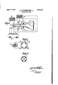
- FIG. 1 illustrates diagrammatically a circuit arrangement according to one embodiment of the invention employing electromagnetic means for setting up said eld
- Figure 2 is an end elevation on an enlarged scale of electromagnetic means for setting up sai eld
- v Figure 3 illustrates electrostatic means for setting up said field.
- meral l indicates a cathode ray tube having a substantially flat end wall 2 on which is provided Aa fluorescent screen 3.
- the tube contains a cathode 4, a cathode screen 5, a rst anode and a second anode l, these electrodes being fed in known manner with suitable potentials derived from a source of potential indicated conventionally by a battery across which is provided a potentiometer 9 to which said electrodes are connected.
- the ring I5 is arranged to surround the path of the beam as shown in Figure 1 and the axis of the ring is arranged coincident with the axis of the beam in its undeflected position and the coils are arranged substantially opposite to the corners of the scanned patch.
- the coils IE5 may be fed with a steady current from a source l1 and the coils are so arranged that they set up Within the ring l5 a eld which increases in intensity outwardly from its axis.
- the end Wall 2 of the cathode ray tube I has a diameter of 12" and said end wall is substantially flat.
- the ring has an internal diameter of 21/2" and an external diameter of 3 and is 1/2 thick.
- Each coil is Wound over 45 of the ring with 35 turns and may be fed with a steady current of 0.6 ampere. It is found that by employing such a eld the electron beam can be caused to trace out a substantially rectangular patch on the screen of the tube and that aberration of the cathode ray beam is reduced and that the focus of the beam can thereby be maintained substantially constant throughout the scanning movement of the beam. The desired amount of correction imparted by the ileld can be adjusted by varying the steady current passing through said coils.
- f .f prises two' .sets of :cuits :i E f and: L2 which are lfed f i l ,with suitable currents: which, if Itl'le'tube lf :is c I ployedl for :television reception,A :are: generated by .f line and; frame irequencysawtoeth :generators it f and ll.A
- a varying current or Voltage may be employed depending on the form of the correction desired. For example, by feeding the coil l5 or the electrodes I8 with a current or voltage of saWtooth Waveform, the field in the region through which the beam is passing at any particular period during the deflecting cycle can be adjusted so as to give an effect equivalent to a constant field of any desired law.
- the varying current or voltage can of course be employed in conjunction with a steady current or voltage.
- a cathode ray tube having means for developing, deflecting, and directing a cathode ray beam toward a target area and in which the radius of curvature of the target differs from the distance from the point of deiection of the beam to the target, a plurality of beam inuencing means positioned adjacent said deflecting means and spaced apart equidistantly a pre-determined number of electrical degrees, and means for encrgizing said beam iniluencing means to produce a circularly symmetrical field about the axis of the beam in its undeected position and which in- 5 6 creases in intensity outwardly from the axis of REFERENCES CITED the beam.
Description
Apnl 12, 1949. E. w. BULL Erm. 2,467,009
' CIRCUIT ARRANGEMENT EMBODYING v CATHODE-RAY TUBES Filed Dec. 12, 1946 57540)' CUIVRE/V7 50i/ME Patented Apr. 12, 1949 UNITED STATES PATENT FFICE CIRCUIT ARRANGEMENT EMBODYING CATHODE-RAY TUBES Application December 12, 1946, Serial No. 715,670 In Great Britain July 28, 1945 Section 1, Public Law 690, August 8, 1946 Patent expires July 28, 1965 3 Claims.
This invention relates to circuit arrangements embodying cathode ray tubes in which the electron beam of the tube is required to be deflected over a surface Within the tube.
In cathode ray tubes employed for television reception the fluorescent screen of the tube is usually provided on the end wall of the tube, said end wall usually being made as flat as possible in order to avoid distortion of the optical image reproduced in the screen. Also in cathoderay tubes employed for television transmission purposes the mosaic screen of the tube is usually at. In deiiecting the cathode ray beam over the surface of such screens it is usually the practice to employ two mutually perpendicular scanning fields and whilst it is possible to cause the scanning beam to trace out a truly rectangular patch on the screen providing that the screen has a surface which approximates to that of a sphere the centre of which is the point about which deflection of the beam occurs, it is found that when the screen is not curved in such a manner the scanned patch is no longer rectangular but is distorted. In cases where the screen is flat or of less curvature than the aforesaid sphere the scanned patch has a pincushion shape and in cases where the screen has a curvature greater than that of said sphere the scanned patch has a barrel shape. In order to correct for distortion of the scanned patch it has been the practice to vary the waveform of the current or voltage employed for deffecting the beam or in the case of electromagnetic scanning so to dispose the conductors of the scanning coils that a eld is produced which diminishes in intensity from the axis of the tube. Although distortion of the scanned patch can be reduced in this manner, it is found, however, that the variation in field intensity is such that considerable aberration or variation of focus of the cathode ray beam occurs at large angles of deection.
The main object of the present invention is to provide a circuit arrangement embodying a cathode ray tube in which improved means are provided for reducing distortion of the scanned According to the invention a circuit arrangement is provided embodying a cathode ray tube and means for deecting the beam of said tube so that it can be caused to scan a patch .on the screen of said tube which patch would be rectangular if the screen had a curvature corresponding to that of a sphere having as its centre the point about which deflection of said beam occurs and wherein the screen has a curvature which is greater or less than that of said sphere and is arranged normally to the axis of said beam and wherein there is provided means for setting up between said screen and said point a eld which increases in intensity outwardly from its axis so as to reduce substantially or eliminate either pincushion or barrel distortion which would occur in the absence of said eld.
Preferably said field is circularly symmetrical about the axis of the beam in its undeflected position, and whilst such a eld is preferred approximately circularly symmetrical elds can be employed.
The deflecting means employed may be either electrostatic or electromagnetic or a combination of both electrostatic and electromagnetic means and the means for setting up said field may also be electrostatic or electromagnetic.
In order that the said invention may be clearly understood and readily carried into effect. the same will now be more fully described with reference to the accompanying drawings, in whichv Figure 1 illustrates diagrammatically a circuit arrangement according to one embodiment of the invention employing electromagnetic means for setting up said eld,
Figure 2 is an end elevation on an enlarged scale of electromagnetic means for setting up sai eld, and v Figure 3 illustrates electrostatic means for setting up said field. s
In Figure 1 of the drawings the reference nu, meral l indicates a cathode ray tube having a substantially flat end wall 2 on which is provided Aa fluorescent screen 3. The tube contains a cathode 4, a cathode screen 5, a rst anode and a second anode l, these electrodes being fed in known manner with suitable potentials derived from a source of potential indicated conventionally by a battery across which is provided a potentiometer 9 to which said electrodes are connected. The electron beam which is generated by the cathode 4 and focussed and accelerated by the electrodes 5, 6 and 'l and which may be modulated by applying suitable modulating pov 1 y f .tion of the beamcccurafthebeam would trace out f f a truly :rectangular :patch on ,the screen.'y .The
. l present .invention .hou/even; concerned :with 1 cases 1in: which fthe Ascreen d:i conforms to; al sur@ 1 face which. has a .curvature :which is i greater or; less: than; that ict said sphere sivhich of: course in-e =cludes thecase in which the screen eoniormstefaf f :dat f surface Landf in; which the screen disposed 1 substantially normally to lth'e axisf or' fthe: beam whenundefiectem f In :suchA =cases: ifthe :bearnf isv i L deflected l over lthe surface f off the screen. :eitherz z :pincushion: or: :barrel distortions :occurs: :in the:
uscannedpatch.; -f l f l f :hilnonc fformfofl come :said: distortion f which; where f a dilat screen .is employed as in' Figure 12 the scanned patch will 3 flrave; a pilnushidn shape; electromagnetic means y zare provided. for setting` up a: @field between the scanning means and; the screen gsad' meanszifor. s'etting' :up :said fe'ld beingy preferably :disposed 2 f lcloseitc! said@ scanning means. fPreferabiy; lthe E field .setz up is circularly symmetrical about the 1 faxis of; the' heaminzits undeected position; Such afield is' :approximated by the arrangement showin I 5in; Figure 2.. As: shownin this: tigure ithei means f ior setting up said: field :comprises ai' circular ring ofr soft' iron l5l which `is 'preferably of laminated invention in' :order to' :overconstruction and is provided with four coils i6 in series-aiding connection Wound toroidally about symmetrically-disposed segments of the ring 15. The ring I5 is arranged to surround the path of the beam as shown in Figure 1 and the axis of the ring is arranged coincident with the axis of the beam in its undeflected position and the coils are arranged substantially opposite to the corners of the scanned patch. The coils IE5 may be fed with a steady current from a source l1 and the coils are so arranged that they set up Within the ring l5 a eld which increases in intensity outwardly from its axis. In one specific example of the invention the end Wall 2 of the cathode ray tube I has a diameter of 12" and said end wall is substantially flat. The ring has an internal diameter of 21/2" and an external diameter of 3 and is 1/2 thick. Each coil is Wound over 45 of the ring with 35 turns and may be fed with a steady current of 0.6 ampere. It is found that by employing such a eld the electron beam can be caused to trace out a substantially rectangular patch on the screen of the tube and that aberration of the cathode ray beam is reduced and that the focus of the beam can thereby be maintained substantially constant throughout the scanning movement of the beam. The desired amount of correction imparted by the ileld can be adjusted by varying the steady current passing through said coils.
The angle over Which each toroidal coil is Wound can be varied according to the correction required in individual cases, and, in general, where a high order of accuracy is required adtentials tothe electrode 'is indicated by the dote: I 'f f t v l ted .line Afl .and is caused to trace-r out 'a- :patch on L f i l :thefluore'scent screen. 3y fby-y deiiecting the beam in two cio-ordinate :directions-.z =As shown lin fFig.-v f
. ure i, the means :for deilectingzthe beam :com.
f .f prises two' .sets of :cuits :i E f and: L2 which are lfed f i l ,with suitable currents: which, if Itl'le'tube lf :is c I ployedl for :television reception,A :are: generated by .f line and; frame irequencysawtoeth :generators it f and ll.A The :deflectingz means' employed for. .dee-c iiecting thebeam i l2= are :such that if :the: screen. f
: 1 i f 3 were disposed .on the .surface oi ta' sphere: hav. 2
i l ing as its centrethe :point about which fdenecaf .other than that shown in Figure :Zimay :be ern-3 f c f fici s :arranged around: the; circumference :ci the :tub s .and :conform :to #the shape: of :a :circulary ring. and f extend overl segments. :of i thev circumference f or f said ringsomewhat less: than: 45?'. Saidclectrodes. are disposed :substantially opposite to the corner f of: the: scanned patch andtocorrect for-pincnsho l distortion-said electrodes fwiil fbe fed with; a sul f able fvzcltage; which isin'egative :with respect. toth wardly firom: its :axis
=' :In cases Where it: is desired to correct forA bar-= :rel fdistortion .the larrangement des.cribedz above s may; be employed but in such: 'ca-'ses the direction f fot current fiowthrough the fc'oilsl lliz Willbe iny the 1 opposite .direction to; that required A'for correcting 1 f lpincushion distortion.` f Further; pincushion 1 .tcrtionz can be :corrected -byf changing Lthe position f :of the coilsfrcativeiyto the corners: offthefscanned f insti-nent :of f the :currentkr in each individuati I coi 2 i :patch .and f employing the same: direction of f curc f f renti'lour' as in the Acase for' correcting barrel fdistortion. and; vice versa.; :An arrangement iof .coi
z c flnstead ci' employing :electromagnetic means r f f r zfor setting up =saidsneld,= electrostatic: means f ma befempioyed shcwninigure said eilectrof-z f f static lmeans mayi comprise: =four electrodes i8` :Whichf may bel :disposed ion fthef Wali lof the tube: al :and suitably: spaced: or separated from the sec nd; anode the: electrode 4B being equi-distanti.
otentialz appliied; to the :second: anode .t ;so` as; t
"' creases ini intensity fO.
c: with the: fbeam its= undeflected position The: fieldset: npzapproxi mates to .a:circulariy; symmetrical neldthat ris` to; -f
. say :azne'ld thelines of: which arel .crnica fconcle lInstead of :applyingasteady :current or `voitage f to the coils I6 or the electrodes I8, a varying current or Voltage may be employed depending on the form of the correction desired. For example, by feeding the coil l5 or the electrodes I8 with a current or voltage of saWtooth Waveform, the field in the region through which the beam is passing at any particular period during the deflecting cycle can be adjusted so as to give an effect equivalent to a constant field of any desired law. The varying current or voltage can of course be employed in conjunction with a steady current or voltage.
Although the invention has been described above as applied to a cathode ray tube employing a uorescent screen, it will be understood that the invention is not limited thereto since it can be applied to other types of cathode ray tubes, such as those employing mosaic screens used in television transmitting tubes, such screens being usually supported in the tube independently of the end wall of the tube.
What We claim is:
1. In cathode ray apparatus wherein there is provided a cathode ray tube having means for developing, deflecting, and directing a cathode ray beam toward a target area and in which the radius of curvature of the target differs from the distance from the point of deiection of the beam to the target, a plurality of beam inuencing means positioned adjacent said deflecting means and spaced apart equidistantly a pre-determined number of electrical degrees, and means for encrgizing said beam iniluencing means to produce a circularly symmetrical field about the axis of the beam in its undeected position and which in- 5 6 creases in intensity outwardly from the axis of REFERENCES CITED the beam.
The following references are of record in the 2. Apparatus in accordance with claim 1 wherein said plurality of beam influencing means le 0f this Patenti Comprising a plurality Of windings each spaced P apart from the other by 45 electrical degrees and all energizing a core member of toroidal shape. Number Name Date 3. Apparatus in accordance with claim 1 2,157,182 Maloi May 9, 1939 wherein said beam influencing means comprise 2,164,931 Maloff July 4, 1939 electrostatic plates spaced apartl 45 from each 2,165,803 Maloi July 11, 1939 other. l0 2,230,111 Gunther Jan.2s,1941 ERIC WILLIAM BULL 2,258,643 De Gier et al. Oct. 14, 1941 2,264,567 Gunther Dec. 2, 1941 MAX ERIC PEMBERTON.
2,406,740 Buckbee sept. 3, 1946
Applications Claiming Priority (1)
| Application Number | Priority Date | Filing Date | Title |
|---|---|---|---|
| GB19378/45A GB605572A (en) | 1945-07-28 | 1945-07-28 | Improvements in or relating to circuit arrangements embodying cathode ray tubes |
Publications (1)
| Publication Number | Publication Date |
|---|---|
| US2467009A true US2467009A (en) | 1949-04-12 |
Family
ID=10128355
Family Applications (1)
| Application Number | Title | Priority Date | Filing Date |
|---|---|---|---|
| US715670A Expired - Lifetime US2467009A (en) | 1945-07-28 | 1946-12-12 | Circuit arrangement embodying cathode-ray tubes |
Country Status (3)
| Country | Link |
|---|---|
| US (1) | US2467009A (en) |
| FR (1) | FR936015A (en) |
| GB (1) | GB605572A (en) |
Cited By (6)
| Publication number | Priority date | Publication date | Assignee | Title |
|---|---|---|---|---|
| US2834901A (en) * | 1954-05-06 | 1958-05-13 | Rca Corp | Cathode ray tube adjunct |
| US2892962A (en) * | 1955-10-07 | 1959-06-30 | Karl F Ross | Electronic lens system |
| US2943219A (en) * | 1955-09-19 | 1960-06-28 | Philco Corp | Beam positioning apparatus for cathode ray tubes |
| US2944173A (en) * | 1958-07-17 | 1960-07-05 | Hazeltine Research Inc | Cathode-ray tube scanning apparatus |
| US3023343A (en) * | 1960-01-11 | 1962-02-27 | Ibm | Information recording and display apparatus |
| US3035199A (en) * | 1957-11-29 | 1962-05-15 | Gen Dynamics Corp | Lens deflection in the electro optical system of a cathode ray tube |
Citations (7)
| Publication number | Priority date | Publication date | Assignee | Title |
|---|---|---|---|---|
| US2157182A (en) * | 1935-12-31 | 1939-05-09 | Rca Corp | Cathode ray deflecting device |
| US2164931A (en) * | 1935-10-31 | 1939-07-04 | Rca Corp | Cathode ray tube deflecting device |
| US2165803A (en) * | 1936-04-25 | 1939-07-11 | Rca Corp | Cathode ray deflecting device |
| US2230111A (en) * | 1938-11-30 | 1941-01-28 | Fernseh Ag | Deflecting device for cathode ray tubes |
| US2258643A (en) * | 1938-04-25 | 1941-10-14 | Philips Nv | Distortion correction for cathode ray tubes |
| US2264567A (en) * | 1938-11-24 | 1941-12-02 | Fernseh Ag | Deflecting device |
| US2406740A (en) * | 1944-02-14 | 1946-09-03 | Farnsworth Television & Radio | Keystone correction apparatus |
-
1945
- 1945-07-28 GB GB19378/45A patent/GB605572A/en not_active Expired
-
1946
- 1946-11-19 FR FR936015D patent/FR936015A/en not_active Expired
- 1946-12-12 US US715670A patent/US2467009A/en not_active Expired - Lifetime
Patent Citations (7)
| Publication number | Priority date | Publication date | Assignee | Title |
|---|---|---|---|---|
| US2164931A (en) * | 1935-10-31 | 1939-07-04 | Rca Corp | Cathode ray tube deflecting device |
| US2157182A (en) * | 1935-12-31 | 1939-05-09 | Rca Corp | Cathode ray deflecting device |
| US2165803A (en) * | 1936-04-25 | 1939-07-11 | Rca Corp | Cathode ray deflecting device |
| US2258643A (en) * | 1938-04-25 | 1941-10-14 | Philips Nv | Distortion correction for cathode ray tubes |
| US2264567A (en) * | 1938-11-24 | 1941-12-02 | Fernseh Ag | Deflecting device |
| US2230111A (en) * | 1938-11-30 | 1941-01-28 | Fernseh Ag | Deflecting device for cathode ray tubes |
| US2406740A (en) * | 1944-02-14 | 1946-09-03 | Farnsworth Television & Radio | Keystone correction apparatus |
Cited By (6)
| Publication number | Priority date | Publication date | Assignee | Title |
|---|---|---|---|---|
| US2834901A (en) * | 1954-05-06 | 1958-05-13 | Rca Corp | Cathode ray tube adjunct |
| US2943219A (en) * | 1955-09-19 | 1960-06-28 | Philco Corp | Beam positioning apparatus for cathode ray tubes |
| US2892962A (en) * | 1955-10-07 | 1959-06-30 | Karl F Ross | Electronic lens system |
| US3035199A (en) * | 1957-11-29 | 1962-05-15 | Gen Dynamics Corp | Lens deflection in the electro optical system of a cathode ray tube |
| US2944173A (en) * | 1958-07-17 | 1960-07-05 | Hazeltine Research Inc | Cathode-ray tube scanning apparatus |
| US3023343A (en) * | 1960-01-11 | 1962-02-27 | Ibm | Information recording and display apparatus |
Also Published As
| Publication number | Publication date |
|---|---|
| GB605572A (en) | 1948-07-27 |
| FR936015A (en) | 1948-07-07 |
Similar Documents
| Publication | Publication Date | Title |
|---|---|---|
| US2431077A (en) | Cathode-ray tube with revolving magnets and adjustable sleeve | |
| US3448316A (en) | Cathode ray tube | |
| US2157182A (en) | Cathode ray deflecting device | |
| US3430099A (en) | Simplified deflection system for plural in-line beam cathode ray tube | |
| US2258643A (en) | Distortion correction for cathode ray tubes | |
| US2212640A (en) | Cathode ray system | |
| US3930185A (en) | Display system with simplified convergence | |
| US2547994A (en) | Electronic microscope | |
| EP0250027B1 (en) | Cathode ray tube having a magnetic focusing lens | |
| US3462638A (en) | Electron beam correction apparatus for color picture tube | |
| US4197487A (en) | Beam-index tube apparatus having deflection field correcting elements | |
| US3504211A (en) | Electron beam control device for use with a cathode ray tube for dynamic correction of electron beam astigmatism and defocusing | |
| US2467009A (en) | Circuit arrangement embodying cathode-ray tubes | |
| US2742589A (en) | Electron beam convergence apparatus | |
| US2108523A (en) | Cathode ray tube | |
| US2572861A (en) | Deflection system for cathode-ray tubes | |
| US2729759A (en) | Beam controlling apparatus | |
| US2533073A (en) | Cathode beam tube | |
| US2678405A (en) | Multibeam convergence controlling system | |
| US2344736A (en) | Television transmitting system | |
| EP0073005A2 (en) | Color cathode ray tube device | |
| US2824267A (en) | Deflection yoke for multi-beam cathode ray tube | |
| US3150284A (en) | Apparatus for use in conjunction with a cathode ray tube to reduce defocusing and astigmatism of an electron beam thereof | |
| US2707246A (en) | Combination focusing-ion trap structures for cathode-ray tubes | |
| US2911563A (en) | Electrostatic lens and deflection system |