US2441635A - Windmill - Google Patents
Windmill Download PDFInfo
- Publication number
- US2441635A US2441635A US598946A US59894645A US2441635A US 2441635 A US2441635 A US 2441635A US 598946 A US598946 A US 598946A US 59894645 A US59894645 A US 59894645A US 2441635 A US2441635 A US 2441635A
- Authority
- US
- United States
- Prior art keywords
- vanes
- rotation
- shaft
- horizontal
- windmill
- Prior art date
- Legal status (The legal status is an assumption and is not a legal conclusion. Google has not performed a legal analysis and makes no representation as to the accuracy of the status listed.)
- Expired - Lifetime
Links
- 241000239290 Araneae Species 0.000 description 4
- 239000012530 fluid Substances 0.000 description 3
- 230000003472 neutralizing effect Effects 0.000 description 3
- 238000010276 construction Methods 0.000 description 2
- 230000002093 peripheral effect Effects 0.000 description 2
- 230000000694 effects Effects 0.000 description 1
- 238000004519 manufacturing process Methods 0.000 description 1
- 230000004048 modification Effects 0.000 description 1
- 238000012986 modification Methods 0.000 description 1
- 230000007935 neutral effect Effects 0.000 description 1
Images

Classifications
-
- F—MECHANICAL ENGINEERING; LIGHTING; HEATING; WEAPONS; BLASTING
- F03—MACHINES OR ENGINES FOR LIQUIDS; WIND, SPRING, OR WEIGHT MOTORS; PRODUCING MECHANICAL POWER OR A REACTIVE PROPULSIVE THRUST, NOT OTHERWISE PROVIDED FOR
- F03D—WIND MOTORS
- F03D3/00—Wind motors with rotation axis substantially perpendicular to the air flow entering the rotor
- F03D3/06—Rotors
- F03D3/062—Rotors characterised by their construction elements
- F03D3/066—Rotors characterised by their construction elements the wind engaging parts being movable relative to the rotor
- F03D3/067—Cyclic movements
-
- F—MECHANICAL ENGINEERING; LIGHTING; HEATING; WEAPONS; BLASTING
- F05—INDEXING SCHEMES RELATING TO ENGINES OR PUMPS IN VARIOUS SUBCLASSES OF CLASSES F01-F04
- F05B—INDEXING SCHEME RELATING TO WIND, SPRING, WEIGHT, INERTIA OR LIKE MOTORS, TO MACHINES OR ENGINES FOR LIQUIDS COVERED BY SUBCLASSES F03B, F03D AND F03G
- F05B2240/00—Components
- F05B2240/20—Rotors
- F05B2240/21—Rotors for wind turbines
- F05B2240/211—Rotors for wind turbines with vertical axis
- F05B2240/218—Rotors for wind turbines with vertical axis with horizontally hinged vanes
-
- F—MECHANICAL ENGINEERING; LIGHTING; HEATING; WEAPONS; BLASTING
- F05—INDEXING SCHEMES RELATING TO ENGINES OR PUMPS IN VARIOUS SUBCLASSES OF CLASSES F01-F04
- F05B—INDEXING SCHEME RELATING TO WIND, SPRING, WEIGHT, INERTIA OR LIKE MOTORS, TO MACHINES OR ENGINES FOR LIQUIDS COVERED BY SUBCLASSES F03B, F03D AND F03G
- F05B2240/00—Components
- F05B2240/20—Rotors
- F05B2240/21—Rotors for wind turbines
- F05B2240/221—Rotors for wind turbines with horizontal axis
-
- F—MECHANICAL ENGINEERING; LIGHTING; HEATING; WEAPONS; BLASTING
- F05—INDEXING SCHEMES RELATING TO ENGINES OR PUMPS IN VARIOUS SUBCLASSES OF CLASSES F01-F04
- F05B—INDEXING SCHEME RELATING TO WIND, SPRING, WEIGHT, INERTIA OR LIKE MOTORS, TO MACHINES OR ENGINES FOR LIQUIDS COVERED BY SUBCLASSES F03B, F03D AND F03G
- F05B2260/00—Function
- F05B2260/70—Adjusting of angle of incidence or attack of rotating blades
- F05B2260/72—Adjusting of angle of incidence or attack of rotating blades by turning around an axis parallel to the rotor centre line
-
- F—MECHANICAL ENGINEERING; LIGHTING; HEATING; WEAPONS; BLASTING
- F05—INDEXING SCHEMES RELATING TO ENGINES OR PUMPS IN VARIOUS SUBCLASSES OF CLASSES F01-F04
- F05B—INDEXING SCHEME RELATING TO WIND, SPRING, WEIGHT, INERTIA OR LIKE MOTORS, TO MACHINES OR ENGINES FOR LIQUIDS COVERED BY SUBCLASSES F03B, F03D AND F03G
- F05B2260/00—Function
- F05B2260/70—Adjusting of angle of incidence or attack of rotating blades
- F05B2260/74—Adjusting of angle of incidence or attack of rotating blades by turning around an axis perpendicular the rotor centre line
-
- Y—GENERAL TAGGING OF NEW TECHNOLOGICAL DEVELOPMENTS; GENERAL TAGGING OF CROSS-SECTIONAL TECHNOLOGIES SPANNING OVER SEVERAL SECTIONS OF THE IPC; TECHNICAL SUBJECTS COVERED BY FORMER USPC CROSS-REFERENCE ART COLLECTIONS [XRACs] AND DIGESTS
- Y02—TECHNOLOGIES OR APPLICATIONS FOR MITIGATION OR ADAPTATION AGAINST CLIMATE CHANGE
- Y02E—REDUCTION OF GREENHOUSE GAS [GHG] EMISSIONS, RELATED TO ENERGY GENERATION, TRANSMISSION OR DISTRIBUTION
- Y02E10/00—Energy generation through renewable energy sources
- Y02E10/70—Wind energy
- Y02E10/74—Wind turbines with rotation axis perpendicular to the wind direction
Definitions
- Patented May 18, 1948 PATENT 6 FFIFCE Henry *V. iverson, LBmdingMm, June 12, 1945,, ,No. 598946 'Elliis invention relates to a windmill, and more particu rly to a d vi e f r tur ing wind power ohanical ener y- A p m y bi d of th s invent on s n ovisionvof an improved windmill characterized "by a series of vanes rotating in a horizontal orbit around a vertical :shaf-t, including means whereby the vanes are oscillated from horizontal to verideal position during the course of rotation thereof.
- An a ditional o ject of "the is the provision of such a device characterized by means whereby adjacent vanes are adapted to he extended upwardly and downwardly from :a rcentra1 horizontal plane, in order to effect a maximum of wind resistance during certain portions of the rotation of "the device, and a minimum “of wind resistance when returned to horizontal position, during other positions of the rotation of the device.
- a further object of the invention is the provision of a hydraulic mechanism associated with each set of blades adapted to turn the same from horizontal to vertical position, and vice versa in accordance with the position of rotation of the assembly.
- a still further object of the invention is the provision of a neutralizing unit, including a hydraulic cylinder, associated with each individual pair of vanes, whereby all of the vanes can be turned to horizontal or neutral position, thus precluding rotation of the device by wind pressure.
- Still another object of the invention is the provision of such a device which will be sturdy and durable in construction, reliable and efficient in operation, and relatively simple and inexpensive to manufacture and assemble.
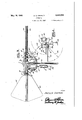
- Figure 1 is a top plan view of one form of device embodying the instant inventive concept
- Figure 2 is a side elevational view of the device shown in Figure l, certain parts thereof being broken away.
- Figure 3 is an enlarged sectional view taken substantially along the line 33 of Figure 1.
- Figure 4 is a sectional view taken substantially 12 along the'l ine lk-4 of Figure 3, and viewed in the direction indicated by the arrows.
- a main drive shaft All is mounted to rotate about a vertical axis, and carried at the upper end of said shaft a spider designated generally TI.
- This spider comprises a central hub portion 12 from therunper end of which nadiate arms l3.
- the outer :ends of alternate arms L3 terminate in .dependin lugs ill while the intermediate arms are provided at their outer ends in depending lugs 15 of .less length than the lugs .IA.
- Formed in the lugs l5 are radial openings 18 which align with an annular series of peripheral sockets I! formed'in the hub 12 adjacent its upper end, and formed in each lug 1-4 near its lower end is a radian opening ill.
- the openings 1-8 align with an annular (series at peripheral sockets 19 formed in the hub 1.2 which latter series of sockets is spaced downwardly from the sockets I nowadays so that the axes of the ape-nines la to lie in a horizontal plane below the axes of the openings !6 and sockets I'I.
- an upper series of radial shafts 20 each of which is rotatable about a horizontal axis which lies perpendicular to the axis of the shaft I0
- each of which is rotatable about a horizontal axis which also lies perpendicular to the axis of shaft ill but below the plane of the axes of the shafts 20.
- blades or vanes 22 Carried adjacent the outer ends of the shafts 20 are blades or vanes 22 which are adapted to move upwardly through a arc to a vertical position as will be more fully hereinafter eX- plained.
- a similar blade or vane 23 iscarried adjacent the outer end of each shaft 2
- each of the shafts 20 carries a segmental gear 24, adapted to mesh with a similar gear segment 25 carried by an adjacent shaft 2!, and each of the shafts 2
- the bases of diametrically opposed cylinders 28 communicate with each other through conduits 30, from which a conduit 3
- the vanes 22 acting on its shaft 20 and being geared by virtue of the gears 25 and 26 to the immediately adjacent lower shaft 2
- V it is necessary to V have only one hydraulic cylinder for each associated pair of shafts 20 and 2
- a rotatable spider a, plurality of rods journaled for rotation in said spider, said rods comprising staggered radial upper and lower rows, vanes secured to each of said rods, gearing between adjacent rods in upper and lower rows to rotate the rods and vanes simultaneously, and hydraulic means connecting diametrically opposite upper and lower rows whereby rotation of a rod in one row will occasion opposite rotation of an opposite rod in the other row, said hydraulic means including fluid filled, cylinders, a connecting passage between diametrically opposite cylinders, pistons connected to each of said rods and operable in said cylinders, and means for moving all of the blades to the inoperative position, said last-mentioned means including a neutralizing cylinder having a piston therein and means for moving said piston to neutralize the fluid pressure in each ofsaid first mentioned cylinders.
Landscapes
- Engineering & Computer Science (AREA)
- Life Sciences & Earth Sciences (AREA)
- Sustainable Development (AREA)
- Sustainable Energy (AREA)
- Chemical & Material Sciences (AREA)
- Combustion & Propulsion (AREA)
- Mechanical Engineering (AREA)
- General Engineering & Computer Science (AREA)
- Wind Motors (AREA)
Description
May 18, 1948- H. v. IVERSON 2,441,635
WINDMILL Filed June 12, 1945 2 Sheets-Sheet l- '30 flenry U. fuersoh H. v. IVERSON WINDMILL 2 Sheets-Sheet 2 Filed June 12,' 1 945 lm /entor flezgry u e/"son,
and
Patented May 18, 1948 PATENT 6 FFIFCE Henry *V. iverson, LBmdingMm, June 12, 1945,, ,No. 598946 'Elliis invention relates to a windmill, and more particu rly to a d vi e f r tur ing wind power ohanical ener y- A p m y bi d of th s invent on s n ovisionvof an improved windmill characterized "by a series of vanes rotating in a horizontal orbit around a vertical :shaf-t, including means whereby the vanes are oscillated from horizontal to verideal position during the course of rotation thereof.
An a ditional o ject of "the is the provision of such a device characterized by means whereby adjacent vanes are adapted to he extended upwardly and downwardly from :a rcentra1 horizontal plane, in order to effect a maximum of wind resistance during certain portions of the rotation of "the device, and a minimum "of wind resistance when returned to horizontal position, during other positions of the rotation of the device.
A further object of the invention is the provision of a hydraulic mechanism associated with each set of blades adapted to turn the same from horizontal to vertical position, and vice versa in accordance with the position of rotation of the assembly.
A still further object of the invention is the provision of a neutralizing unit, including a hydraulic cylinder, associated with each individual pair of vanes, whereby all of the vanes can be turned to horizontal or neutral position, thus precluding rotation of the device by wind pressure.
Still another object of the invention is the provision of such a device which will be sturdy and durable in construction, reliable and efficient in operation, and relatively simple and inexpensive to manufacture and assemble.
Other objects reside in the combinations of elements, arrangements of parts, and features of construction all as will be more fully pointed out hereinafter and disclosed in the accompanying drawings wherein there is shown a preferred embodiment of this inventive concept.
In the drawings, wherein like reference numerals denote like parts throughout the several views:
Figure 1 is a top plan view of one form of device embodying the instant inventive concept,
Figure 2 is a side elevational view of the device shown in Figure l, certain parts thereof being broken away.
Figure 3 is an enlarged sectional view taken substantially along the line 33 of Figure 1.
Figure 4 is a sectional view taken substantially 12 along the'l ine lk-4 of Figure 3, and viewed in the direction indicated by the arrows.
Referring to the drawings in detail, a main drive shaft All is mounted to rotate about a vertical axis, and carried at the upper end of said shaft a spider designated generally TI. This spider comprises a central hub portion 12 from therunper end of which nadiate arms l3. The outer :ends of alternate arms L3 terminate in .dependin lugs ill while the intermediate arms are provided at their outer ends in depending lugs 15 of .less length than the lugs .IA. Formed in the lugs l5 are radial openings 18 which align with an annular series of peripheral sockets I! formed'in the hub 12 adjacent its upper end, and formed in each lug 1-4 near its lower end is a radian opening ill. The openings 1-8 align with an annular (series at peripheral sockets 19 formed in the hub 1.2 which latter series of sockets is spaced downwardly from the sockets I?! so that the axes of the ape-nines la to lie in a horizontal plane below the axes of the openings !6 and sockets I'I.
Mounted in the openings l6 and sockets I1 is an upper series of radial shafts 20 each of which is rotatable about a horizontal axis which lies perpendicular to the axis of the shaft I0, and mounted in the openings l8 and the sockets I9 is a second or lower series of radial shafts 2| each of which is rotatable about a horizontal axis which also lies perpendicular to the axis of shaft ill but below the plane of the axes of the shafts 20.
Carried adjacent the outer ends of the shafts 20 are blades or vanes 22 which are adapted to move upwardly through a arc to a vertical position as will be more fully hereinafter eX- plained. A similar blade or vane 23 iscarried adjacent the outer end of each shaft 2|, but unlike the vanes 22, each vane 23 is adapted to move downwardly through a 90 arc to a vertical position.
As best shown in Figure 4 each of the shafts 20 carries a segmental gear 24, adapted to mesh with a similar gear segment 25 carried by an adjacent shaft 2!, and each of the shafts 2| carries a lever 26, to which is secured a piston rod 21, extending downwardly into a hydraulic cylinder 28, and having a piston 29 at the extremity thereof. The bases of diametrically opposed cylinders 28 communicate with each other through conduits 30, from which a conduit 3| leads to a neutralizing cylinder 32, positioned within which is a piston 33 having a piston rod 34, adapted to be moved in any desired manner, as for example, manually. As best shown in of the vanes 22 acting on its shaft 20, and being geared by virtue of the gears 25 and 26 to the immediately adjacent lower shaft 2| and its associated vane correspondingly turns a diametrically opposed lower shaft 2!.
With the arrangement shown, it is necessary to V have only one hydraulic cylinder for each associated pair of shafts 20 and 2|, said rotation of one of the shafts will actuate the cylinder, and correspondingly actuate the opposite shaft of the pair to present a combined vane surface 22 and 23 in vertical position to be engaged by the wind, or conversely in horizontal position to present a minimum of resistance thereto on the return rotation.
It will be readily understood that movement of the piston rod 34 acts through the iluid contained in the cylinder 23 to level the fluid content in the cylinders 28 forcing the pistons respectively to their uppermost points, and thus turning all blades to horizontal position, in such manner as to render the device inoperative.
From the foregoing it will now be seen that there is herein provided an improved windmill, accomplishing all the objects of this invention, and others including many advantages of great practical utility and commercial importance.
As many embodiments may be made of this inventive concept, and as many modifications may be made in the embodiment hereinbefore shown 4 and described, it is to be understood that all matter herein is to be interpreted merely as illustrative and not in a limiting sense.
I claim:
In a device of the character described, a rotatable spider, a, plurality of rods journaled for rotation in said spider, said rods comprising staggered radial upper and lower rows, vanes secured to each of said rods, gearing between adjacent rods in upper and lower rows to rotate the rods and vanes simultaneously, and hydraulic means connecting diametrically opposite upper and lower rows whereby rotation of a rod in one row will occasion opposite rotation of an opposite rod in the other row, said hydraulic means including fluid filled, cylinders, a connecting passage between diametrically opposite cylinders, pistons connected to each of said rods and operable in said cylinders, and means for moving all of the blades to the inoperative position, said last-mentioned means including a neutralizing cylinder having a piston therein and means for moving said piston to neutralize the fluid pressure in each ofsaid first mentioned cylinders.
- HENRY V. IVERSON.
REFERENCES CITED The following references are of record in the file of this patent:
'7 UNITED STATES PATENTS
Priority Applications (1)
| Application Number | Priority Date | Filing Date | Title |
|---|---|---|---|
| US598946A US2441635A (en) | 1945-06-12 | 1945-06-12 | Windmill |
Applications Claiming Priority (1)
| Application Number | Priority Date | Filing Date | Title |
|---|---|---|---|
| US598946A US2441635A (en) | 1945-06-12 | 1945-06-12 | Windmill |
Publications (1)
| Publication Number | Publication Date |
|---|---|
| US2441635A true US2441635A (en) | 1948-05-18 |
Family
ID=24397578
Family Applications (1)
| Application Number | Title | Priority Date | Filing Date |
|---|---|---|---|
| US598946A Expired - Lifetime US2441635A (en) | 1945-06-12 | 1945-06-12 | Windmill |
Country Status (1)
| Country | Link |
|---|---|
| US (1) | US2441635A (en) |
Cited By (18)
| Publication number | Priority date | Publication date | Assignee | Title |
|---|---|---|---|---|
| US2707521A (en) * | 1950-04-27 | 1955-05-03 | Rogers Joseph Norman | Wind motor |
| US4090811A (en) * | 1976-09-23 | 1978-05-23 | Greene Michael L | Fluid current motor |
| US4142832A (en) * | 1977-04-25 | 1979-03-06 | Clifton Woodrow W | Fluid current motor |
| US4348156A (en) * | 1980-03-17 | 1982-09-07 | United Technologies Corporation | Blade pitch actuation system |
| US4377372A (en) * | 1981-11-09 | 1983-03-22 | Carl Stutzman | Wind turbine |
| FR2599432A1 (en) * | 1986-05-28 | 1987-12-04 | Prud Homme Christian | Wind machine with a vertical axis and articulated blades |
| EP0270136A1 (en) * | 1986-10-23 | 1988-06-08 | Horace Schuurwegen | Windmill with rotatable vanes |
| US4822239A (en) * | 1988-05-13 | 1989-04-18 | Tsipov Michael E | Vertical axis windmill |
| US5083902A (en) * | 1986-12-18 | 1992-01-28 | Rhodes Winfred A | Reverting wind wheel |
| FR2805311A1 (en) * | 2000-02-22 | 2001-08-24 | Jean Marie Golsse | Open type six bladed radial turbine for connecting to electricity generator |
| WO2002033253A2 (en) * | 2000-10-16 | 2002-04-25 | Hasim Vatandas | Vertical-axis wind turbine |
| US6543999B1 (en) | 2002-02-15 | 2003-04-08 | James Van Polen | Windmill |
| US20040001752A1 (en) * | 2001-03-20 | 2004-01-01 | Noble James D. | Turbine apparatus and method |
| WO2006136117A1 (en) * | 2005-06-20 | 2006-12-28 | Jan Taus | Windturbine comprising a vertical rotational axis |
| US20100129218A1 (en) * | 2008-09-09 | 2010-05-27 | Christopherson Myron L | Wind turbine |
| US20120034079A1 (en) * | 2010-08-25 | 2012-02-09 | Pterofin, Inc. | Harnessing Flowing Fluids to Create Torque |
| US20150118050A1 (en) * | 2012-07-06 | 2015-04-30 | Wilhelmus Helena Hendrikus Joosten | Wind Turbine, its Use and a Vane for Use in the Turbine |
| WO2022006611A1 (en) | 2020-07-09 | 2022-01-13 | Johann Gruber | Wind turbine |
Citations (6)
| Publication number | Priority date | Publication date | Assignee | Title |
|---|---|---|---|---|
| DE12667C (en) * | M. F. SCHMIDT in Görlitz | Horizontal wind turbine with blades that open and close automatically depending on the wind direction | ||
| US713094A (en) * | 1901-05-01 | 1902-11-11 | Henry Grist | Wind-motor. |
| US1319766A (en) * | 1919-10-28 | Wibtd-motor | ||
| US1915689A (en) * | 1932-08-26 | 1933-06-27 | Irwin T Moore | Windmill |
| US2139982A (en) * | 1936-06-24 | 1938-12-13 | Charles L Smith | Propeller blade pitch regulator |
| US2170911A (en) * | 1938-08-15 | 1939-08-29 | Hardy H Raulerson | Wind motor |
-
1945
- 1945-06-12 US US598946A patent/US2441635A/en not_active Expired - Lifetime
Patent Citations (6)
| Publication number | Priority date | Publication date | Assignee | Title |
|---|---|---|---|---|
| DE12667C (en) * | M. F. SCHMIDT in Görlitz | Horizontal wind turbine with blades that open and close automatically depending on the wind direction | ||
| US1319766A (en) * | 1919-10-28 | Wibtd-motor | ||
| US713094A (en) * | 1901-05-01 | 1902-11-11 | Henry Grist | Wind-motor. |
| US1915689A (en) * | 1932-08-26 | 1933-06-27 | Irwin T Moore | Windmill |
| US2139982A (en) * | 1936-06-24 | 1938-12-13 | Charles L Smith | Propeller blade pitch regulator |
| US2170911A (en) * | 1938-08-15 | 1939-08-29 | Hardy H Raulerson | Wind motor |
Cited By (26)
| Publication number | Priority date | Publication date | Assignee | Title |
|---|---|---|---|---|
| US2707521A (en) * | 1950-04-27 | 1955-05-03 | Rogers Joseph Norman | Wind motor |
| US4090811A (en) * | 1976-09-23 | 1978-05-23 | Greene Michael L | Fluid current motor |
| US4142832A (en) * | 1977-04-25 | 1979-03-06 | Clifton Woodrow W | Fluid current motor |
| US4348156A (en) * | 1980-03-17 | 1982-09-07 | United Technologies Corporation | Blade pitch actuation system |
| US4377372A (en) * | 1981-11-09 | 1983-03-22 | Carl Stutzman | Wind turbine |
| FR2599432A1 (en) * | 1986-05-28 | 1987-12-04 | Prud Homme Christian | Wind machine with a vertical axis and articulated blades |
| EP0270136A1 (en) * | 1986-10-23 | 1988-06-08 | Horace Schuurwegen | Windmill with rotatable vanes |
| US5083902A (en) * | 1986-12-18 | 1992-01-28 | Rhodes Winfred A | Reverting wind wheel |
| US4822239A (en) * | 1988-05-13 | 1989-04-18 | Tsipov Michael E | Vertical axis windmill |
| FR2805311A1 (en) * | 2000-02-22 | 2001-08-24 | Jean Marie Golsse | Open type six bladed radial turbine for connecting to electricity generator |
| WO2002033253A2 (en) * | 2000-10-16 | 2002-04-25 | Hasim Vatandas | Vertical-axis wind turbine |
| WO2002033253A3 (en) * | 2000-10-16 | 2002-08-01 | Hasim Vatandas | Vertical-axis wind turbine |
| US20040265127A1 (en) * | 2001-03-20 | 2004-12-30 | Noble James D. | Turbine apparatus and method |
| US20040001752A1 (en) * | 2001-03-20 | 2004-01-01 | Noble James D. | Turbine apparatus and method |
| US6682302B2 (en) * | 2001-03-20 | 2004-01-27 | James D. Noble | Turbine apparatus and method |
| US6929450B2 (en) | 2001-03-20 | 2005-08-16 | James D. Noble | Turbine apparatus and method |
| US6543999B1 (en) | 2002-02-15 | 2003-04-08 | James Van Polen | Windmill |
| WO2004015266A1 (en) * | 2002-08-13 | 2004-02-19 | Noble James D | Turbine apparatus and method |
| AU2003258233B2 (en) * | 2002-08-13 | 2006-10-12 | James D. Noble | Turbine apparatus and method |
| WO2006136117A1 (en) * | 2005-06-20 | 2006-12-28 | Jan Taus | Windturbine comprising a vertical rotational axis |
| US20100129218A1 (en) * | 2008-09-09 | 2010-05-27 | Christopherson Myron L | Wind turbine |
| US7997863B2 (en) * | 2008-09-09 | 2011-08-16 | Christopherson Myron L | Wind turbine |
| US20120034079A1 (en) * | 2010-08-25 | 2012-02-09 | Pterofin, Inc. | Harnessing Flowing Fluids to Create Torque |
| US20150118050A1 (en) * | 2012-07-06 | 2015-04-30 | Wilhelmus Helena Hendrikus Joosten | Wind Turbine, its Use and a Vane for Use in the Turbine |
| US10145358B2 (en) * | 2012-07-06 | 2018-12-04 | Wilhelmus Helena Hendrikus Joosten | Wind turbine, its use and a vane for use in the turbine |
| WO2022006611A1 (en) | 2020-07-09 | 2022-01-13 | Johann Gruber | Wind turbine |
Similar Documents
| Publication | Publication Date | Title |
|---|---|---|
| US2441635A (en) | Windmill | |
| US1835018A (en) | Turbine having its rotating shaft transverse to the flow of the current | |
| CN105383655B (en) | Crank block type blade oscillating mechanism and the voith schneider propeller including the mechanism | |
| CN205186489U (en) | Slider -crank formula blade swing mechanism and including straight wing propeller of this mechanism | |
| US3367424A (en) | Hydraulic machine having adjustable blade runner | |
| US1964347A (en) | Windmill | |
| US4218184A (en) | Windmill construction | |
| EP2783101B1 (en) | Turbomachine having one or more blade wheels with positively driven moving blades. | |
| RU2015106526A (en) | UNIVERSAL HYDRO-WIND POWER PLANT (UHVSU) | |
| US2687280A (en) | Pump-turbine | |
| US1794930A (en) | Wind-driven power device | |
| US2029503A (en) | Automatic change pitch propeller | |
| EP3101270B1 (en) | Device for reversing a blade of a runner unit | |
| US2872875A (en) | Hydraulic power units | |
| US1456008A (en) | Aeroplane propeller | |
| US2171732A (en) | Hydromotor | |
| US1718304A (en) | Wind motor | |
| US1352859A (en) | Windmill | |
| US1931158A (en) | Hydraulic turbine | |
| US3259213A (en) | Friction and hydraulic brake for arresting gear means | |
| US2938397A (en) | Transmission having adjustable hydraulic clutches for reversing and free movement | |
| DE2639732A1 (en) | Rotating anemometer for measuring wind speed - has pivoted vanes rising to horizontal on lee side of rotation | |
| US1558645A (en) | Windmill | |
| CA2969485C (en) | Hydraulic turbomachine | |
| US2705538A (en) | Propeller with feathering blades |