US2405237A - Electronic trigger circuit with time-delay - Google Patents
Electronic trigger circuit with time-delay Download PDFInfo
- Publication number
- US2405237A US2405237A US413694A US41369441A US2405237A US 2405237 A US2405237 A US 2405237A US 413694 A US413694 A US 413694A US 41369441 A US41369441 A US 41369441A US 2405237 A US2405237 A US 2405237A
- Authority
- US
- United States
- Prior art keywords
- potential
- anode
- pulse
- control electrode
- time
- Prior art date
- Legal status (The legal status is an assumption and is not a legal conclusion. Google has not performed a legal analysis and makes no representation as to the accuracy of the status listed.)
- Expired - Lifetime
Links
Images
Classifications
-
- H—ELECTRICITY
- H03—ELECTRONIC CIRCUITRY
- H03K—PULSE TECHNIQUE
- H03K3/00—Circuits for generating electric pulses; Monostable, bistable or multistable circuits
- H03K3/02—Generators characterised by the type of circuit or by the means used for producing pulses
- H03K3/04—Generators characterised by the type of circuit or by the means used for producing pulses by the use, as active elements, of vacuum tubes only, with positive feedback
- H03K3/05—Generators characterised by the type of circuit or by the means used for producing pulses by the use, as active elements, of vacuum tubes only, with positive feedback using means other than a transformer for feedback
- H03K3/06—Generators characterised by the type of circuit or by the means used for producing pulses by the use, as active elements, of vacuum tubes only, with positive feedback using means other than a transformer for feedback using at least two tubes so coupled that the input of one is derived from the output of another, e.g. multivibrator
- H03K3/10—Generators characterised by the type of circuit or by the means used for producing pulses by the use, as active elements, of vacuum tubes only, with positive feedback using means other than a transformer for feedback using at least two tubes so coupled that the input of one is derived from the output of another, e.g. multivibrator monostable
Definitions
- This invention relates to electrical apparatus for generating rectangular pulses, and more particularly to an apparatus for producing a rectangular pulse upon application of a single momentary pulse thereto.
- Another object is to provide an electrical apparatus having novel means for producing, a rectangular shaped pulse upon application of a single momentary pulse thereto.
- Another object is to provide in an electrical apparatu of the above character novel means for determining the time-interval of the produced pulse independently of the applied pulse.
- Another object is to provide an electrical apparatus of comparatively simple construction for reliably producing an electrical impulse upon application of a single momentary pulse to the circuit.
- Still another object of the invention is to provide an apparatus of the above type wherein the magnitude and time-interval of the produced pulse are independent of similar characteristics of the applied pulse.
- Still another object is to provide an electrical apparatus of the foregoing character wherein the 1 magnitude and time-interval of the produced pulse is determined by certain components of the apparatus and which may be easily varied throughout wide limits.
- Still another object is to provide an electrical apparatus for generating an electrical pulse upon application of a single momentary pulse thereto of such construction to reduce regenerative action to a minimum.
- Still another object is toprovide an electricalapparatus having input and output terminals ineluding novel means wherein the potential of the output terminal abruptly changes, upon application of a momentary voltage at the input terminal, to a value independent of the applied voltage, and wherein the potential of the output terminal remains at such value for a predetermined period of time determined by certain components of the apparatus.
- Still another object is to provide an electrical apparatus including a pair of electron discharge devices interconnected in such a manner whereby the potential of the devices is normally maintained ata predetermined value, and wherein the potential of one of the devices abruptly varies upon application of a single momentary pulse theretoto abruptly vary the potential of the other device to a second predetermined value.
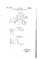
- Fig. l is a schematic illustration of an electrical apparatus embodying the principles of the present invention.
- Fig. 2 shows the voltage curve of a pulse produced by the apparatu disclosed in Fig. 1
- Fig. 3 shows the voltage curve of the single momentary pulse applied to the apparatus shown Referring more particularly to Fig. l of the drawing, an electrical apparatus embodying the.
- the electrodes of devices I0 and II may be included in a single envelope, such as a duplex-triode, for example.
- Ihe cathodes I2 and I3 are connected together and are in turn connected to ground potential through common resistanc I8, whereas the anodes of each of the devices are maintained positive with respect to the cathodes by mappropriate source of potential I9, the positive terminal of which is connected to anodes I4 and I5 through resistances 2B and 2
- Control electrode l6, of device 10, i connected to ground potential through resistance 22, while control electrode 11 is connected to the positive terminal of source I9, through variable resistance 23, in order that devices It and H may be controlled.
- control electrode I! is also connected to anode M, of device I0, through capacitance 24.
- An input terminal 25 is connected to the cathodes through suitable capacitance 26, and an output terminal 21 is provided which is connected between anode l and resistance 2!, thus segregating the same from other components of the circuit to thus reduce regenerative action to aminimum.
- control electrode ll of such value that device I i draws current
- is selected to provide a drop in potential at anode l5 whereby the potential of output terminal 21 will normally be maintained at a substantially zero value.
- Resistance 18 is properly selected to provide a drop in potential at control electrode l6, when device [I draws current, so that control electrode 16 is normally biased to a sufiicient negative value to cut oil device l0 and thu prevent anode M from drawing current.
- Anode l4 therefore, will normally be maintained at high potential, substantially equal to the potential of source I9.
- the present invention provides means for abruptly varying the potential of device I0 upon application of a singlemomentary pulse atinput terminal 25, to abruptly vary the potential of device H, and hence output terminal 21, to a second predetermined value. It has been found when a single momentary negative pulse, of any suitable magnitude greater than a few volts, is applied to input terminal 25, the potential difierence between control electrode it and cathode I2 suddenly changes and allows device lll to abruptly draw current. At the instant current flows in device ID a sudden drop in potential at anode l4 occurs because of the drop of the voltage at resistance '20.
- means are provided for maintaining the output terminal at a substantially constant high predetermined potential throughout a predetermined period of time, independently of the time-interval of the single momentary pulse applied at input terminal 25, and forabruptly decrease to a substantially zero value after lapse of such predetermined period of time.
- such means includes capacitance 24 and resistance 23, which function to maintain control electrode H sufiiciently negatively biased, following the flow of the large negative pulse thereto, for a period of time equal to the product of the values of the capacitance and resistance.
- the capacitance and resistance are to be selected to provide the time-delay desired, or to determine the time-interval during which it is desired to maintain the output terminal at a high potential.
- control electrode I! gradually leaks ofi, and after lapse of the predetermined period of time, the control electrode will be driven positive, which abruptly allows device H to again draw current.
- the potential at the output terminal abruptly drops to a substantially zero value, because of the drop of the voltage at resistance 2
- Resistance 23 may be of the variable type, if desired, so that the time-interval of high potential at output terminal 2'! may be manually varied throughout certain limits. During the time-interval when device I I is not passing current, there will be a small drop of voltage at resistance 18, and consequently device It) will be drawing current throughout such interval.
- the present invention thus provides a novel electrical apparatus for generating a rectangular pulse upon application of a single momentary pulse thereto.
- the apparatus is of such construction and operates in such a manner that the magnitude and time-interval of the output pulse is entirely independent of magnitude and time interval of the input pulse.
- the apparatus is further characterized by novel construction wherein the output terminal is not connected adjacent to other components of the circuit thus reducing regenerative action to aminimum, and thus operating at a high efficiency and in a recausing the potential of the output terminal to 15' liable manner.
- an apparatus for producing a rectangular pulse upon application of a single pulse thereto comprising a pair of electron discharge devices each having at least a cathode, anode and control electrode, an input terminal connected to the cathode of one of said devices, an output terminal connected to the anode of the other device, means normally maintaining the anode of said other device at substantially zero potential, means normally maintaining the anode of said one device at a high potential, means causing a drop in the potential of the anode of said one device upon application of the single pulse at said input terminal, means responsive to the drop in potential at the anode of said one device for causing an increase in the potential of the anode of said other device, and means responsive to a potential increase at the anode of said other device for further reducing the potential at the anode of said one device, the last-named means including a direct connection between said cathodes.
- an apparatus for producing a rectangular pulse upon application of a single pulse thereto comprising a pair of electron discharge devices each having at least a cathode, anode and control electrode, an input terminal connected to the cathode of one of said devices, an output terminal connected to the anode of the other device, means normally maintaining the anode of said other device at substantially zero potential, means normally maintaining the anode of said one device at a high potential, means causing a drop in the potential of the anode of said one device upon application of th single pulse at said input terminal, means responsive to the drop in potential at the anode of said one device for causing an increase in the potential of 3.
- an apparatus for producing a rectangular pulse in response to a single momentary pulse applied thereto comprising a pair of vacuum tubes each having a cathode, control electrode and an anode, a source of potential, circuit means connecting said source to said tubes in such a manner to maintain the anode positive with respect to the cathodes, a resistance in each anode circuit, a resistance common to both cathode circuits, an output terminal connected between the anode and corresponding anode resistance of one of said tubes, means normally applying a positive bia on the control electrode of said one tube whereby the anode draws current and the potential on the output terminal is substantially zero, means maintaining a negative bias on the control electrode of said other tube whereby the anode of said other tube does not draw current and is at a high potential, means applying a single momentary pulse to the cathode of said other tube whereby the anode of said other tube draws current causing a potential drop at the anode thereof, means including capacitance means connecting the control electrode of said one tube
- a pair of vacuum tubes each having a cathode, an anode and a control electrode, a source of potential, means including a resistance connected to each of said anodes for applying positive potential from said source to said anodes, resistance means for applying the positive potential of said source to the control electrode of one of said tubes, resistance means applying negative potential from said ource to the control electrode of the other tube, means including a resistance connecting both of said cathodes to negative potential of said source, and a condenser coupling the anode of said other tube to the control electrode of said one tube.
- a pair of vacuum tubes each having at least a cathode, an anode and a control electrode, means applying a positive potential to said anodes, means including a resistance common to the cathodes of each of said tubes, means biasing the control electrode of one of said tubes negative with respect to its cathode, a condenser coupling the anode of said one tube to the control grid of the other said tube, and means applying a positive bias to the control electrode of said other tube thereby normally sustaining said other tube conducting and said one tube non-conducting.
Landscapes
- Engineering & Computer Science (AREA)
- Power Engineering (AREA)
- Generation Of Surge Voltage And Current (AREA)
Description
Patented Aug. 6, 1.946
ELECTRONIC TRIGGER CIRCUIT WITH THEE-DELAY Arthur J. Ruhlig, Washington, D. C.
Application October 4, 1941, Serial No. 413,694
(Granted under the act of March 3, 1883, as amended April 30, 1928; 370 0. G. 757
5 Claims.
This invention relates to electrical apparatus for generating rectangular pulses, and more particularly to an apparatus for producing a rectangular pulse upon application of a single momentary pulse thereto.
Various electrical apparatus have been provided heretofore, such as non-oscillating multivibrators, for generating a pulse upon application of a single momentary pulse to the circuit. However, the prior arrangements ar not adequate in that the magnitude and time-interval of the produced pulse is either dependent upon the characte of the applied pulse or is so limited by inherent characteristics of the circuit that a pulse suitable for numerous applications cannot be obtained thereby. Moreover, the circuits of the prior apparatus are extremely complex which tends to produce excessive regenerative action therein as well as reducing the eificiency and reliability of the apparatus.
It is therefore an object of the present invention to provide an electrical apparatus of such construction to overcome the disadvantages enumerated heretofore.
Another objectis to provide an electrical apparatus having novel means for producing, a rectangular shaped pulse upon application of a single momentary pulse thereto.
Another object is to provide in an electrical apparatu of the above character novel means for determining the time-interval of the produced pulse independently of the applied pulse.
Another object is to provide an electrical apparatus of comparatively simple construction for reliably producing an electrical impulse upon application of a single momentary pulse to the circuit.
Still another object of the invention is to provide an apparatus of the above type wherein the magnitude and time-interval of the produced pulse are independent of similar characteristics of the applied pulse.
Still another object is to provide an electrical apparatus of the foregoing character wherein the 1 magnitude and time-interval of the produced pulse is determined by certain components of the apparatus and which may be easily varied throughout wide limits.
Still another object is to provide an electrical apparatus for generating an electrical pulse upon application of a single momentary pulse thereto of such construction to reduce regenerative action to a minimum.
Still another object is toprovide an electricalapparatus having input and output terminals ineluding novel means wherein the potential of the output terminal abruptly changes, upon application of a momentary voltage at the input terminal, to a value independent of the applied voltage, and wherein the potential of the output terminal remains at such value for a predetermined period of time determined by certain components of the apparatus.
Still another object is to provide an electrical apparatus including a pair of electron discharge devices interconnected in such a manner whereby the potential of the devices is normally maintained ata predetermined value, and wherein the potential of one of the devices abruptly varies upon application of a single momentary pulse theretoto abruptly vary the potential of the other device to a second predetermined value.
Other objects and features of the invention will appear more fully from the following detailed description when. considered together with the accompanying drawing which disclosed one embodiment of the invention. It is to be expressly understood, however, that the drawing is designed for purposes of illustration only, and not as a definition of the limits of the invention, reference being had to the appended claims for the latter purpose.
In the drawing:
Fig. l is a schematic illustration of an electrical apparatus embodying the principles of the present invention;
Fig. 2 shows the voltage curve of a pulse produced by the apparatu disclosed in Fig. 1, and Fig. 3 shows the voltage curve of the single momentary pulse applied to the apparatus shown Referring more particularly to Fig. l of the drawing, an electrical apparatus embodying the.
principles of the present invention is disclosed therein including a pair of electron discharge devices I0 and I I, of the triode type, each respectively having a cathode I2 and I3, an anode I 4 and I5, and a control electrode i6 and I1. When a more compact arrangement is desired, the electrodes of devices I0 and II may be included in a single envelope, such as a duplex-triode, for example. Ihe cathodes I2 and I3 are connected together and are in turn connected to ground potential through common resistanc I8, whereas the anodes of each of the devices are maintained positive with respect to the cathodes by mappropriate source of potential I9, the positive terminal of which is connected to anodes I4 and I5 through resistances 2B and 2| respectively. Control electrode l6, of device 10,, i connected to ground potential through resistance 22, while control electrode 11 is connected to the positive terminal of source I9, through variable resistance 23, in order that devices It and H may be controlled. For a purpose that will appear more fully hereinafter, control electrode I! is also connected to anode M, of device I0, through capacitance 24. An input terminal 25 is connected to the cathodes through suitable capacitance 26, and an output terminal 21 is provided which is connected between anode l and resistance 2!, thus segregating the same from other components of the circuit to thus reduce regenerative action to aminimum.
With the foregoing construction, a positive bias is normally maintained on control electrode ll of such value that device I i draws current, and resistanc 2| is selected to provide a drop in potential at anode l5 whereby the potential of output terminal 21 will normally be maintained at a substantially zero value. Resistance 18 is properly selected to provide a drop in potential at control electrode l6, when device [I draws current, so that control electrode 16 is normally biased to a sufiicient negative value to cut oil device l0 and thu prevent anode M from drawing current. Anode l4, therefore, will normally be maintained at high potential, substantially equal to the potential of source I9.
As heretofore stated, the present invention provides means for abruptly varying the potential of device I0 upon application of a singlemomentary pulse atinput terminal 25, to abruptly vary the potential of device H, and hence output terminal 21, to a second predetermined value. It has been found when a single momentary negative pulse, of any suitable magnitude greater than a few volts, is applied to input terminal 25, the potential difierence between control electrode it and cathode I2 suddenly changes and allows device lll to abruptly draw current. At the instant current flows in device ID a sudden drop in potential at anode l4 occurs because of the drop of the voltage at resistance '20. The extent of such potential drop at anode i4 depends upon resistance 20, which is to be of such value as to provide a comparatively large drop in potential following the instant the input pulse is applied to the input terminal. At the instant the potential of anode 14 drops a lar e negative pulse is transferred through capacitance 24 to control electrode ll, of device H, to drive the control electrode sufliciently negative to abruptly out off this device and abruptly terminate the flow of anode current. When the device H ceases to draw current the potential of anode l5, and hence thepotential of output terminal 21, will abruptly increase, from the substantially zero value to a high value substantially equal to the potential of source [9. When it is desired to utilize a positive momentary pulse to change the bias on control electrode [6, in order to cause device I0 to abruptly draw current, such input voltage is applied to the control electrode 16 through an input terminal 28 and capacitance '29, shown in broken lines on the drawing;
Inaccordance' with the principles of the present invention means are provided for maintaining the output terminal at a substantially constant high predetermined potential throughout a predetermined period of time, independently of the time-interval of the single momentary pulse applied at input terminal 25, and forabruptly decrease to a substantially zero value after lapse of such predetermined period of time. As shown in the drawing, such means includes capacitance 24 and resistance 23, which function to maintain control electrode H sufiiciently negatively biased, following the flow of the large negative pulse thereto, for a period of time equal to the product of the values of the capacitance and resistance. The capacitance and resistance are to be selected to provide the time-delay desired, or to determine the time-interval during which it is desired to maintain the output terminal at a high potential. During such time interval the negative bias on control electrode I! gradually leaks ofi, and after lapse of the predetermined period of time, the control electrode will be driven positive, which abruptly allows device H to again draw current. At the instant device H commences to draw current the potential at the output terminal abruptly drops to a substantially zero value, because of the drop of the voltage at resistance 2|. Resistance 23 may be of the variable type, if desired, so that the time-interval of high potential at output terminal 2'! may be manually varied throughout certain limits. During the time-interval when device I I is not passing current, there will be a small drop of voltage at resistance 18, and consequently device It) will be drawing current throughout such interval. However, at the instant device ll again commences to pass current, the drop in voltage at resistance l8 will increase to thereby cause device IE to return to the normal state wherein no anode current is flowing and the anode is maintained at a high potential, substantially equal to the potential of source l9.
With reference to Figs. 2 and 3, curves of the output and input voltages, and the relationships therebetween are respectively shown. The potential of the output terminal is shown at a substantially zero value until the input voltage is impressed on the circuit, at which instant, the output voltage abruptly increases to a predetermined value, determined by certain components included in the circuit, independently of the magnitude of the input voltage. The output voltage then remains substantially constant at the high value for a predetermined time-interval T, such interval being determined by the product of the value of capacitance 24 and resistance 23. When time-interval T lapses, the output voltage abruptly drops to a substantially zero value, and remains at such value until a momentary input voltage is again applied to the circuit, in which case the foregoing operation would reoccur. From the above it can be readily seen that the output voltage, or the potential of the output terminal, is entirely independent of the characteristics of the input voltage, the latter only functioning as a trigger to initiate eneration of the output pulse,
The present invention thus provides a novel electrical apparatus for generating a rectangular pulse upon application of a single momentary pulse thereto. The apparatus is of such construction and operates in such a manner that the magnitude and time-interval of the output pulse is entirely independent of magnitude and time interval of the input pulse. The apparatus is further characterized by novel construction wherein the output terminal is not connected adjacent to other components of the circuit thus reducing regenerative action to aminimum, and thus operating at a high efficiency and in a recausing the potential of the output terminal to 15' liable manner.
Although only one embodiment of the present invention has been shown and described in detail heretofore, it is to be expressly understood that various changes and substitutions may be made therein without departing from the spirit of the invention, as well understood by those skilled in the art. Reference therefore will be had to the appended claims as a definition of the limits of the invention.
The invention described herein may be manufactured and used by or for the Government of the United States of America for governmental purposes without the payment of any royalties thereon or therefor.
What is claimed is:
1. In an apparatus for producing a rectangular pulse upon application of a single pulse thereto comprising a pair of electron discharge devices each having at least a cathode, anode and control electrode, an input terminal connected to the cathode of one of said devices, an output terminal connected to the anode of the other device, means normally maintaining the anode of said other device at substantially zero potential, means normally maintaining the anode of said one device at a high potential, means causing a drop in the potential of the anode of said one device upon application of the single pulse at said input terminal, means responsive to the drop in potential at the anode of said one device for causing an increase in the potential of the anode of said other device, and means responsive to a potential increase at the anode of said other device for further reducing the potential at the anode of said one device, the last-named means including a direct connection between said cathodes.
2. In an apparatus for producing a rectangular pulse upon application of a single pulse thereto comprising a pair of electron discharge devices each having at least a cathode, anode and control electrode, an input terminal connected to the cathode of one of said devices, an output terminal connected to the anode of the other device, means normally maintaining the anode of said other device at substantially zero potential, means normally maintaining the anode of said one device at a high potential, means causing a drop in the potential of the anode of said one device upon application of th single pulse at said input terminal, means responsive to the drop in potential at the anode of said one device for causing an increase in the potential of 3. In an apparatus for producing a rectangular pulse in response to a single momentary pulse applied thereto, comprising a pair of vacuum tubes each having a cathode, control electrode and an anode, a source of potential, circuit means connecting said source to said tubes in such a manner to maintain the anode positive with respect to the cathodes, a resistance in each anode circuit, a resistance common to both cathode circuits, an output terminal connected between the anode and corresponding anode resistance of one of said tubes, means normally applying a positive bia on the control electrode of said one tube whereby the anode draws current and the potential on the output terminal is substantially zero, means maintaining a negative bias on the control electrode of said other tube whereby the anode of said other tube does not draw current and is at a high potential, means applying a single momentary pulse to the cathode of said other tube whereby the anode of said other tube draws current causing a potential drop at the anode thereof, means including capacitance means connecting the control electrode of said one tube to the anode of the other tube whereby a negative bias is applied to the control electrode of said one tube upon drop in potential at the anode of said other tube thus causing an abrupt cessation of current flow therein and abruptly increasing the potential of the anode thereof, and resistance means connected to the control electrode of said one tube for maintaining the negative bias on the control electrode thereof for a predetermined period of time.
4. In an apparatus of the class described, a pair of vacuum tubes each having a cathode, an anode and a control electrode, a source of potential, means including a resistance connected to each of said anodes for applying positive potential from said source to said anodes, resistance means for applying the positive potential of said source to the control electrode of one of said tubes, resistance means applying negative potential from said ource to the control electrode of the other tube, means including a resistance connecting both of said cathodes to negative potential of said source, and a condenser coupling the anode of said other tube to the control electrode of said one tube.
5. In apparatus of the class described, a pair of vacuum tubes each having at least a cathode, an anode and a control electrode, means applying a positive potential to said anodes, means including a resistance common to the cathodes of each of said tubes, means biasing the control electrode of one of said tubes negative with respect to its cathode, a condenser coupling the anode of said one tube to the control grid of the other said tube, and means applying a positive bias to the control electrode of said other tube thereby normally sustaining said other tube conducting and said one tube non-conducting.
ARTHUR J. RUHLIG.
Priority Applications (1)
| Application Number | Priority Date | Filing Date | Title |
|---|---|---|---|
| US413694A US2405237A (en) | 1941-10-04 | 1941-10-04 | Electronic trigger circuit with time-delay |
Applications Claiming Priority (1)
| Application Number | Priority Date | Filing Date | Title |
|---|---|---|---|
| US413694A US2405237A (en) | 1941-10-04 | 1941-10-04 | Electronic trigger circuit with time-delay |
Publications (1)
| Publication Number | Publication Date |
|---|---|
| US2405237A true US2405237A (en) | 1946-08-06 |
Family
ID=23638242
Family Applications (1)
| Application Number | Title | Priority Date | Filing Date |
|---|---|---|---|
| US413694A Expired - Lifetime US2405237A (en) | 1941-10-04 | 1941-10-04 | Electronic trigger circuit with time-delay |
Country Status (1)
| Country | Link |
|---|---|
| US (1) | US2405237A (en) |
Cited By (46)
| Publication number | Priority date | Publication date | Assignee | Title |
|---|---|---|---|---|
| US2454815A (en) * | 1944-10-03 | 1948-11-30 | Standard Telephones Cables Ltd | Multichannel pulse communication system employing complex multivibrator modulators |
| US2465925A (en) * | 1944-05-18 | 1949-03-29 | Rca Corp | Radio control system |
| US2470464A (en) * | 1942-08-03 | 1949-05-17 | Sylvania Electric Prod | Timing and phase control circuits |
| US2495826A (en) * | 1946-09-18 | 1950-01-31 | Rca Corp | Locking and control circuit in a diversity telegraphy receiver |
| US2510139A (en) * | 1944-05-18 | 1950-06-06 | Rca Corp | Radio control system |
| US2513954A (en) * | 1942-09-28 | 1950-07-04 | Gen Electric | Synchronized pulse generator |
| US2526551A (en) * | 1946-04-20 | 1950-10-17 | Bell Telephone Labor Inc | Delayed-action pulse repeater |
| US2535247A (en) * | 1946-04-20 | 1950-12-26 | Emi Ltd | Synchronizing circuit |
| US2541981A (en) * | 1948-09-17 | 1951-02-20 | Ben R Smutek | Concrete block packing machine |
| US2549875A (en) * | 1944-08-22 | 1951-04-24 | Williams Frederic Calland | Thermionic valve circuits |
| US2551280A (en) * | 1949-01-29 | 1951-05-01 | Gen Electric | Pulse delay circuit |
| US2556934A (en) * | 1947-10-18 | 1951-06-12 | Du Mont Allen B Lab Inc | Variable delay circuit |
| US2557770A (en) * | 1946-05-21 | 1951-06-19 | Gen Electric | Time base circuit |
| US2562171A (en) * | 1948-07-07 | 1951-07-31 | Robert C Butman | Stabilized multivibrator |
| US2562660A (en) * | 1943-12-04 | 1951-07-31 | Chance Britton | Pulse generating circuit |
| US2573354A (en) * | 1945-07-26 | 1951-10-30 | Rca Corp | Variable frequency multivibrator |
| US2575203A (en) * | 1947-02-14 | 1951-11-13 | James O Coit Jr | Film advancing mechanism in a soundpicture strip projector |
| US2578557A (en) * | 1946-01-25 | 1951-12-11 | Rca Corp | Electric timing device |
| US2586409A (en) * | 1947-06-04 | 1952-02-19 | Emi Ltd | Electrical pulse generating circuits |
| US2632103A (en) * | 1950-06-06 | 1953-03-17 | Maurice W Horrell | Stabilized pulse circuit |
| US2632847A (en) * | 1946-02-04 | 1953-03-24 | Jr John C Reed | Pulse forming circuit |
| US2659008A (en) * | 1951-09-11 | 1953-11-10 | Gen Electric | Electronic control circuit |
| US2672283A (en) * | 1948-09-03 | 1954-03-16 | Ibm | Electronic multiplier |
| US2679586A (en) * | 1950-09-27 | 1954-05-25 | Gen Electric | Pulse widening circuit |
| US2681411A (en) * | 1943-12-16 | 1954-06-15 | Us Navy | Linear sweep circuits |
| US2688078A (en) * | 1946-02-21 | 1954-08-31 | Us Navy | Multivibrator |
| US2696554A (en) * | 1945-10-16 | 1954-12-07 | Andrew V Haeff | Microwave signal generator |
| US2706247A (en) * | 1949-10-14 | 1955-04-12 | Jacobs | Means and method for storing information in digital computers |
| US2739238A (en) * | 1952-07-21 | 1956-03-20 | Ibm | End of record detector |
| US2754417A (en) * | 1943-11-24 | 1956-07-10 | Jr George A Brettell | Non-inverting amplifier relay system |
| US2757282A (en) * | 1952-12-20 | 1956-07-31 | Hughes Aircraft Co | Multivibrator circuits |
| US2789217A (en) * | 1946-02-28 | 1957-04-16 | Bell Telephone Labor Inc | Frequency dividing electrical circuit |
| US2797317A (en) * | 1952-04-02 | 1957-06-25 | Gen Electric | Wave generation circuits |
| US2838661A (en) * | 1953-05-15 | 1958-06-10 | Jeffrey C Chu | Binary storage element |
| US2858427A (en) * | 1953-04-29 | 1958-10-28 | Rca Corp | Stabilized cathode-coupled multivibrator |
| US2879384A (en) * | 1954-06-29 | 1959-03-24 | Rca Corp | Phase synchronizing systems |
| US2882400A (en) * | 1955-10-17 | 1959-04-14 | Gen Electric | Trigger circuit |
| US2885547A (en) * | 1953-06-16 | 1959-05-05 | Gen Precision Lab Inc | Pulse train genera tor with variable pulse length |
| US2894128A (en) * | 1954-12-24 | 1959-07-07 | Ibm | Mono-stable multivibrator |
| US2898478A (en) * | 1957-03-21 | 1959-08-04 | Bendix Aviat Corp | Reduction of multivibrator recovery time |
| US2920247A (en) * | 1955-08-12 | 1960-01-05 | Gen Motors Corp | Stable multivibrator |
| US2968748A (en) * | 1957-03-21 | 1961-01-17 | Bendix Corp | Monostable multivibrator and amplifier circuit |
| US3001139A (en) * | 1957-05-27 | 1961-09-19 | Gen Electric | Duo-switch gate circuit operable with positive or negative pulses |
| US3036303A (en) * | 1959-08-27 | 1962-05-22 | Curtiss Wright Corp | Multiple chart course tracing system |
| US3087152A (en) * | 1948-07-01 | 1963-04-23 | Aircraft Radio Corp | Radar beacon receiver for positionmodulated pulse signals |
| US3175162A (en) * | 1961-08-04 | 1965-03-23 | James B Winn | Nondiscriminating, bipolar monostable multivibrator |
-
1941
- 1941-10-04 US US413694A patent/US2405237A/en not_active Expired - Lifetime
Cited By (46)
| Publication number | Priority date | Publication date | Assignee | Title |
|---|---|---|---|---|
| US2470464A (en) * | 1942-08-03 | 1949-05-17 | Sylvania Electric Prod | Timing and phase control circuits |
| US2513954A (en) * | 1942-09-28 | 1950-07-04 | Gen Electric | Synchronized pulse generator |
| US2754417A (en) * | 1943-11-24 | 1956-07-10 | Jr George A Brettell | Non-inverting amplifier relay system |
| US2562660A (en) * | 1943-12-04 | 1951-07-31 | Chance Britton | Pulse generating circuit |
| US2681411A (en) * | 1943-12-16 | 1954-06-15 | Us Navy | Linear sweep circuits |
| US2510139A (en) * | 1944-05-18 | 1950-06-06 | Rca Corp | Radio control system |
| US2465925A (en) * | 1944-05-18 | 1949-03-29 | Rca Corp | Radio control system |
| US2549875A (en) * | 1944-08-22 | 1951-04-24 | Williams Frederic Calland | Thermionic valve circuits |
| US2454815A (en) * | 1944-10-03 | 1948-11-30 | Standard Telephones Cables Ltd | Multichannel pulse communication system employing complex multivibrator modulators |
| US2573354A (en) * | 1945-07-26 | 1951-10-30 | Rca Corp | Variable frequency multivibrator |
| US2696554A (en) * | 1945-10-16 | 1954-12-07 | Andrew V Haeff | Microwave signal generator |
| US2578557A (en) * | 1946-01-25 | 1951-12-11 | Rca Corp | Electric timing device |
| US2632847A (en) * | 1946-02-04 | 1953-03-24 | Jr John C Reed | Pulse forming circuit |
| US2688078A (en) * | 1946-02-21 | 1954-08-31 | Us Navy | Multivibrator |
| US2789217A (en) * | 1946-02-28 | 1957-04-16 | Bell Telephone Labor Inc | Frequency dividing electrical circuit |
| US2526551A (en) * | 1946-04-20 | 1950-10-17 | Bell Telephone Labor Inc | Delayed-action pulse repeater |
| US2535247A (en) * | 1946-04-20 | 1950-12-26 | Emi Ltd | Synchronizing circuit |
| US2557770A (en) * | 1946-05-21 | 1951-06-19 | Gen Electric | Time base circuit |
| US2495826A (en) * | 1946-09-18 | 1950-01-31 | Rca Corp | Locking and control circuit in a diversity telegraphy receiver |
| US2575203A (en) * | 1947-02-14 | 1951-11-13 | James O Coit Jr | Film advancing mechanism in a soundpicture strip projector |
| US2586409A (en) * | 1947-06-04 | 1952-02-19 | Emi Ltd | Electrical pulse generating circuits |
| US2556934A (en) * | 1947-10-18 | 1951-06-12 | Du Mont Allen B Lab Inc | Variable delay circuit |
| US3087152A (en) * | 1948-07-01 | 1963-04-23 | Aircraft Radio Corp | Radar beacon receiver for positionmodulated pulse signals |
| US2562171A (en) * | 1948-07-07 | 1951-07-31 | Robert C Butman | Stabilized multivibrator |
| US2672283A (en) * | 1948-09-03 | 1954-03-16 | Ibm | Electronic multiplier |
| US2541981A (en) * | 1948-09-17 | 1951-02-20 | Ben R Smutek | Concrete block packing machine |
| US2551280A (en) * | 1949-01-29 | 1951-05-01 | Gen Electric | Pulse delay circuit |
| US2706247A (en) * | 1949-10-14 | 1955-04-12 | Jacobs | Means and method for storing information in digital computers |
| US2632103A (en) * | 1950-06-06 | 1953-03-17 | Maurice W Horrell | Stabilized pulse circuit |
| US2679586A (en) * | 1950-09-27 | 1954-05-25 | Gen Electric | Pulse widening circuit |
| US2659008A (en) * | 1951-09-11 | 1953-11-10 | Gen Electric | Electronic control circuit |
| US2797317A (en) * | 1952-04-02 | 1957-06-25 | Gen Electric | Wave generation circuits |
| US2739238A (en) * | 1952-07-21 | 1956-03-20 | Ibm | End of record detector |
| US2757282A (en) * | 1952-12-20 | 1956-07-31 | Hughes Aircraft Co | Multivibrator circuits |
| US2858427A (en) * | 1953-04-29 | 1958-10-28 | Rca Corp | Stabilized cathode-coupled multivibrator |
| US2838661A (en) * | 1953-05-15 | 1958-06-10 | Jeffrey C Chu | Binary storage element |
| US2885547A (en) * | 1953-06-16 | 1959-05-05 | Gen Precision Lab Inc | Pulse train genera tor with variable pulse length |
| US2879384A (en) * | 1954-06-29 | 1959-03-24 | Rca Corp | Phase synchronizing systems |
| US2894128A (en) * | 1954-12-24 | 1959-07-07 | Ibm | Mono-stable multivibrator |
| US2920247A (en) * | 1955-08-12 | 1960-01-05 | Gen Motors Corp | Stable multivibrator |
| US2882400A (en) * | 1955-10-17 | 1959-04-14 | Gen Electric | Trigger circuit |
| US2898478A (en) * | 1957-03-21 | 1959-08-04 | Bendix Aviat Corp | Reduction of multivibrator recovery time |
| US2968748A (en) * | 1957-03-21 | 1961-01-17 | Bendix Corp | Monostable multivibrator and amplifier circuit |
| US3001139A (en) * | 1957-05-27 | 1961-09-19 | Gen Electric | Duo-switch gate circuit operable with positive or negative pulses |
| US3036303A (en) * | 1959-08-27 | 1962-05-22 | Curtiss Wright Corp | Multiple chart course tracing system |
| US3175162A (en) * | 1961-08-04 | 1965-03-23 | James B Winn | Nondiscriminating, bipolar monostable multivibrator |
Similar Documents
| Publication | Publication Date | Title |
|---|---|---|
| US2405237A (en) | Electronic trigger circuit with time-delay | |
| US2418521A (en) | Impulse measuring device | |
| US2404918A (en) | Counting system | |
| US2644897A (en) | Transistor ring counter | |
| US2310105A (en) | Counter circuit | |
| US2384379A (en) | Electrical impulse counting circuits | |
| US3283256A (en) | "n" stable multivibrator | |
| US2692334A (en) | Electrical circuit arrangement for effecting integration and applications thereof | |
| US2575516A (en) | Glow tube switch | |
| US2555999A (en) | Reset circuit for eccles-jordan triggered multivibrator circuits | |
| US2874333A (en) | Thyratron pulser for inductive loads | |
| US2685049A (en) | Coincidence circuit | |
| US3040189A (en) | Monostable multivibrator controlling a threshold circuit | |
| US2630550A (en) | Gas tube ionizer and process | |
| US2462897A (en) | Electronic pulse shaping circuit | |
| US2549764A (en) | Pulse generator | |
| US3008088A (en) | Synchronized multivibrator with selectable clamping means for rendering it inoperative | |
| US2558178A (en) | Glow tube counter | |
| US2863048A (en) | Clipper-amplifier and pulse generator circuit | |
| US2819396A (en) | Electronic trigger circuit | |
| US2544684A (en) | Gas tube control apparatus | |
| US2501620A (en) | Wave generating circuits | |
| US2554994A (en) | Electronic switching circuit | |
| US2844723A (en) | Stable triggered circuit having novel output circuits | |
| US2560691A (en) | Voltage regulated multiple amplifier for pulses |