US2372016A - Unloader valve - Google Patents
Unloader valve Download PDFInfo
- Publication number
- US2372016A US2372016A US459045A US45904542A US2372016A US 2372016 A US2372016 A US 2372016A US 459045 A US459045 A US 459045A US 45904542 A US45904542 A US 45904542A US 2372016 A US2372016 A US 2372016A
- Authority
- US
- United States
- Prior art keywords
- valve
- conduit
- connection
- pressure
- spring
- Prior art date
- Legal status (The legal status is an assumption and is not a legal conclusion. Google has not performed a legal analysis and makes no representation as to the accuracy of the status listed.)
- Expired - Lifetime
Links
- 239000007788 liquid Substances 0.000 description 29
- 239000012530 fluid Substances 0.000 description 19
- 230000000452 restraining effect Effects 0.000 description 4
- 208000036366 Sensation of pressure Diseases 0.000 description 1
- 230000002159 abnormal effect Effects 0.000 description 1
- 230000000740 bleeding effect Effects 0.000 description 1
- 230000000694 effects Effects 0.000 description 1
- 238000007789 sealing Methods 0.000 description 1
- JLYXXMFPNIAWKQ-UHFFFAOYSA-N γ Benzene hexachloride Chemical compound ClC1C(Cl)C(Cl)C(Cl)C(Cl)C1Cl JLYXXMFPNIAWKQ-UHFFFAOYSA-N 0.000 description 1
Images

Classifications
-
- F—MECHANICAL ENGINEERING; LIGHTING; HEATING; WEAPONS; BLASTING
- F16—ENGINEERING ELEMENTS AND UNITS; GENERAL MEASURES FOR PRODUCING AND MAINTAINING EFFECTIVE FUNCTIONING OF MACHINES OR INSTALLATIONS; THERMAL INSULATION IN GENERAL
- F16K—VALVES; TAPS; COCKS; ACTUATING-FLOATS; DEVICES FOR VENTING OR AERATING
- F16K17/00—Safety valves; Equalising valves, e.g. pressure relief valves
- F16K17/02—Safety valves; Equalising valves, e.g. pressure relief valves opening on surplus pressure on one side; closing on insufficient pressure on one side
- F16K17/04—Safety valves; Equalising valves, e.g. pressure relief valves opening on surplus pressure on one side; closing on insufficient pressure on one side spring-loaded
- F16K17/044—Safety valves; Equalising valves, e.g. pressure relief valves opening on surplus pressure on one side; closing on insufficient pressure on one side spring-loaded with more than one spring
-
- F—MECHANICAL ENGINEERING; LIGHTING; HEATING; WEAPONS; BLASTING
- F16—ENGINEERING ELEMENTS AND UNITS; GENERAL MEASURES FOR PRODUCING AND MAINTAINING EFFECTIVE FUNCTIONING OF MACHINES OR INSTALLATIONS; THERMAL INSULATION IN GENERAL
- F16K—VALVES; TAPS; COCKS; ACTUATING-FLOATS; DEVICES FOR VENTING OR AERATING
- F16K17/00—Safety valves; Equalising valves, e.g. pressure relief valves
- F16K17/02—Safety valves; Equalising valves, e.g. pressure relief valves opening on surplus pressure on one side; closing on insufficient pressure on one side
- F16K17/04—Safety valves; Equalising valves, e.g. pressure relief valves opening on surplus pressure on one side; closing on insufficient pressure on one side spring-loaded
- F16K17/042—Safety valves; Equalising valves, e.g. pressure relief valves opening on surplus pressure on one side; closing on insufficient pressure on one side spring-loaded with locking or disconnecting arrangements
-
- Y—GENERAL TAGGING OF NEW TECHNOLOGICAL DEVELOPMENTS; GENERAL TAGGING OF CROSS-SECTIONAL TECHNOLOGIES SPANNING OVER SEVERAL SECTIONS OF THE IPC; TECHNICAL SUBJECTS COVERED BY FORMER USPC CROSS-REFERENCE ART COLLECTIONS [XRACs] AND DIGESTS
- Y10—TECHNICAL SUBJECTS COVERED BY FORMER USPC
- Y10T—TECHNICAL SUBJECTS COVERED BY FORMER US CLASSIFICATION
- Y10T137/00—Fluid handling
- Y10T137/2496—Self-proportioning or correlating systems
- Y10T137/2559—Self-controlled branched flow systems
- Y10T137/2574—Bypass or relief controlled by main line fluid condition
- Y10T137/2605—Pressure responsive
- Y10T137/2622—Bypass or relief valve responsive to pressure downstream of outlet valve
-
- Y—GENERAL TAGGING OF NEW TECHNOLOGICAL DEVELOPMENTS; GENERAL TAGGING OF CROSS-SECTIONAL TECHNOLOGIES SPANNING OVER SEVERAL SECTIONS OF THE IPC; TECHNICAL SUBJECTS COVERED BY FORMER USPC CROSS-REFERENCE ART COLLECTIONS [XRACs] AND DIGESTS
- Y10—TECHNICAL SUBJECTS COVERED BY FORMER USPC
- Y10T—TECHNICAL SUBJECTS COVERED BY FORMER US CLASSIFICATION
- Y10T74/00—Machine element or mechanism
- Y10T74/18—Mechanical movements
- Y10T74/18992—Reciprocating to reciprocating
Description
20,1945. A. ROCKWELL 2,372,016
UNLOADER VALVE v I Filed Sept. 19, 1942 2 Sheets-Sheet -1 INVENTOR l l'gwai'd H. Rockwell ATTORNEY -March 20, 1945, 5 ROCKWELL v 2,372,016
UNLOADER VALVE Filed Sept. 19, 1942 2 Sheets-Sheeh 2 t5 i 1 is N T a i E N O g 1 k n] N INVENTOR Edward "/1 E06 icwell ATI'ORNEY 3 Patented Mar.20,1945
UNITED STATES PATENT OFFICE UNLOADER VALVE Edward A. Roc kwell, Cleveland, Ohio Application Septemberm, 1942, SerialNo. 459,045
' 18 Claims. (01. 137- 53) My invention relates particularly to automatically operated valves but is applicable, for ex ample, especially to the operation of unloader valves such for instance as such valves used in connection with pumps.
The objector my invention is to provide automatic valves adapted to operate with precision and certainty. A further. object is to provide such valves having great rapidity of'action. A further object is to provide valves of this character for unloading pumps. Another object is to provide such valves in hydraulic systems for operating the wheel-retracting under-carriages of airplanes. Further objects of my invention will appear from the detailed description of the same hereinafter. is so constructed as to accumulate a spring pressure to operate a valve in both directions of operation and then providea positive trigger action which releases the accumulated spring pressure to forcibly snap the valve oil or on its seat.
While my invention is capable of being carried out in many different ways, for the purpose of illustration I have shown only one form of my invention in the accompanyingdrawings in which- Furthermore, this apparatus Fig. 1 is a vertical section of a unloader valve made in accordance with my invention; and
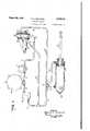
Fig.. 2 is a diagrammatic representation of a pump circuit in which the same is adapted to be used, as applied, for example, to the operation of an hydraulic jack, such for instance as the jack used in operating the retracting under-carriages for the-wheels of an airplane.
In the drawings, I have shown a pump l of any desired character, but as, for example, a continuously operating gear pump which may be driven from the engine of an airplane in any desired way. The pump I is connected by a pipe 2 to an inlet port 3 of a valve cam'ng 4 which may be supported on the airplane in any desired manner. The port 3 leads to a valve chamber 5 which is closed at one end by a screw ring 6 having an opening I which is sealed by an annular rubber seal 8 held in place by a screwplug'Q provided with a squared head II). A screw ring II is carried over the outside of the screw ring 6 and the plug 9. In the interior of the plug 9 there is a fluted recess l2 for receiving an end l3, having a fluted end H. of a release valve operating rod i5 for adjusting spring tensions. Supported around the plug 9 there is a helical spring l8, one end of which-rests against the screw ring 6 and the other end of which extends into an annular release valve I! where it rests ainst a shoulder 18 therein. The said release valve I! has thereon a sleeve 19 having an annular rubber seal 20 arranged to slide within the screw ring 8. At the left hand end of said valve there is a conical valve element 2| which cooperates with an annular insertable valve seat 22 supported within a lateral passageway 23 in the valve casing 4. The sleeve I9 is an annular balanced valve member which has the effect of balancing the large valve l1 so that it can be opened by small operating forces. Accordingly, the light spring 18 can be used whichis of only sufficient strength to return the valve I! to its seat.
The said passageway. 23 leads to an exhaust port' 24 which communicates with a return pipe 25. The said spring l6 normally keeps the conical valve member 2! on its seat 22 and parts are associated with the valve operating rod I5 for unseating the said valve member 2: when the pressure delivered by the unloader valve mechanism reaches a certain degree. For this purpose, on the valve operating rod l5 there are, tightly secured in recesses, annular stops or split rings 26 and 21. Adjacent to the split ring 26 there is a spring supporting sleeve 28 having a flange 29 to support a helical spring 30. The flange 29 rests against a split ring 3| located in a recess in a spring housing 32. The spring housing 32 has a restricted annular end 33 which is slidably carried upon the valve operating rod l5. On the outside of the spring housing 32 there is an annular flange 34 which acts as an interrupted surface cooperating with a series of balls 35 located around the housing 32 in recesses 35a and pressed towards the same by an annular helical spring 36 forming a complete uninterrupted circle within an annular recess 31 which is contained in an auxiliary valve casing 38 provided with a flange 39 for securing the same to the valve casing 4 by means of screws 40, a gasket 4i being provided to make a tight joint. In the recess 3? there is located a portion of the valve casing d forming a spring retaining ring 42 against which one end of a strong helical spring 43 rests, the said spring 43 being located lindrical chamber 44 in the auxiliary casing 38, said chamber 44' and passageway 23 being a discharge chamber. spring 33 is supported by a disk operating rod l5 on which it is held in place by a screw-threaded sleeve 46 having longitudinal grooves 41, in one of which a key pin 48, passing through the auxiliary casing 38, is adapted to slide to permit adjustment of the tension of the 45 on the valve spring 43. This position of the disk 45 is made in a transverse cy- The other end of the helical.
secure owing to the fact that it stops against the left face of the split ring 21, On the right-hand face of the split ring 21 there isa spring sleeve 49 having a flange 50 which rests against a split ring in a recess within a spring housing I2. A helical spring 53 is located around the rod it between the spring sleeve 49 and the spring housing 62. The left-hand end 54 of the valve operating rod I5 is provided with a stop extension 58a and a number of annular oil recesses 55 for sealing the same and said end 54 is adapted to act as a piston so as to be moved by the oil pressure in a chamber 56 which communicates with a passageway 51 in said auxiliary casing 38 and which communicates with a passageway 58 in the valve casing 4. A tight connection is made between the passageways 51 and 58 by a tube 59 having around the same a rubber ring 80 located at the joint between the casings 4 and 88. The said passageway 58, at the right-hand end thereof, leads to a vertical chamber 6! in the casing 4, which is closed by a screw-plug 62 having a projection 63 thereon to act as a guide for a helical spring 64, the lower end of which rests upon the top of a check valve 65 cooperating with an annular valve seat 66 carried in said chamber 6|. A port 61 connects the chamber 6| with the chamber 5. At the side of the chamber 8! there is an outlet port 68 which leads to a pipe 69 which may act as or be an accumulator for conveying the pressure liquid to a hand valve In for controlling the supply of the pressure liquid to the respective ends of a cylinder ll of a jack, which may be used, for example, for controlling the extending and retracting gear of one or more of the wheels of an airplane. While any type of valve 10 might be used for this purpose, as shown diagrammatically, it is comprised of two crossed passageways l2 and 13, one of which is adapted to connect the pipe 69 to the cylinder H by a pipe 14 while the other pasageway connects the other end of a cylinder II by a pipe I5 to a pipe '16 leading to the pipe 15 and thence by a pipe H to a filter l8 and a pipe Bleeding to areservoir 80 and from the said reservoir 80 by a pipe 8! to the intake of the pump I. In otherwords, the hand valve 10 is so arranged that when it supplies the pressure liquid to either end of the cylinder II the other end thereof may be connected to the return pipe to the reservoir, although it is to be understood that any other known type of valve'mechanism can be used for I the supply and discharge of the pressure liquid from the jack. It will of course be understood,
also, that the cylinder 1| of the jack may have a bracket 82 for its attachment to the airplane and a piston rod 83, which is moved by a piston 84. for moving the particular wheel or wheels to which it may be attached.
In the operation of my invention, assuming that the airplane engine is being operated, the pump I will be driven accordingly and liquid therefrom is available to be supplied by the pipe 2 through the check valve 65 to the pipe 69 and thence to either end of the extending and retracting mechanism for the airplane wheels operated by the cylinder ll of the jack provided for the same. It will of course be understood that there may be one such jack with its manual operating valve provided for operating each particular wheel of the airplane. When the pres sure of the liquid which is thus supplied through the pipe 69 reaches any desired given maximum, this pressure, which is conveyed also through the passageway 51, will move the piston end 54 in opposition to the spring 43. This movement will continue until it reaches a position compressing the spring 83, until flnally'the lateral pressure exerted by the annular flange 34 on the balls 35 is sumcient to overcome the pressure exerted on the balls 35 by the annular helical spring 36, whereupon the flange 34 will be moved suddenly and quickly past the balls 35 to the right side of said balls. This will bring the end of the spring housing 32 against the valve I! suddenly so as to open the same with a snap action, thus releasing the pressure liquid to be returned by the pipe to the reservoir 80 and back'to the pump I until such time as the pressure within the pipe 69 is lowered sufliciently to close the valve I1. However, as the pressure is lowered and before .said valve l1 becomes closed, the valve operating rod IE will move to the left, while the spring 43 is expanding, resulting in compressing the spring until such time that the force exerted by the flange 34 towards the left is sufficient to overcome the force of the annular helical spring 36, whereupon, under the influence of the spring 43,
- thefiange 34 will suddenly move to the left side of the balls 35, thus closing the valve I! suddenly and effectively with a snap action. Thus, the unloader valve mechanism will continue to operate in the manner described above t maintain the given pressure being supplied through the pipe 68 and in a most efiective manner, inasmuch as the valve ll will always be moved suddenly and definitely in a minimum time interval to immediately change any abnormal condition of pressure in the pipe 69, thus maintaining it' substantially constant at all times.
While I have described my invention above in detail I wish it to be understood that many changes may be made therein without departing from the spirit of the same.
I claim:
1. A valve mechanism comprising a valve, a conduit having a, delivery outlet for supplying a pressure fluid, connected to said valve, a discharge port for liquid controlled by .said valve, a discharge chamber connected to said port, a part adapted to be moved by the pressure in said conduit, an element with an interrupted surface having a yielding connection to said part comprising means for urging the element in opposite directions located in said chamber, resilient means for forcing the part in one direction, a connection in substantially constant communication with said conduit for receiving liquid therefrom for forcing it constantly in the other direction, and a. quick-action device connected to said element and including a movable member engaging said interrupted surface, having a spring adapted suddenly to open or close the connection of said valve to said discharge port from a given intermediate position of said element substantially immediately upon the movement of the element from the intermediate position in each of its directions of movement.
2. A valve mechanism comprising a valve, a conduit having a delivery ,outlet for supplying a pressure fluid, connected to said valve, a check valve in advance of said conduit and beyond said valve, a discharge port for liquid controlled by said valve, a discharge chamber connected to said port, a part adapted to be moved by the pressure in said conduit beyond the position of the check valve, an element with an interrupted surface having a yielding connection to said part comprising means for urging the element resilient means for forcing the part in one direction, a connection to said conduit for forcing it in the other direction, and a quick-action device connected to said. element and including a movable member engaging said interrupted surface, having a spring adapted to open or close the connection of said valve to said discharge port by the position of said element in each of its directions of movement.
3. In combination, a source of liquid pressure, a valve mechanism comprising a valve, a conduit leading from said source and having a delivery outlet for supplying a pressure fluid, connected to said valve, a discharge port for liquid leading back to said source, controlled by said valve, a discharge chamber connected to said port, a part adapted to be moved by the pressure in said conduit, an element with an interrupted surface having a yielding connection to said part com prising means for urging the element in opposite directions located in said chamber, resilient means for forcing the part in one direction, a
connection in substantially constant communication with said conduit for receiving liquid therefrom' for forcing it constantly in the other direction, and a quick-action device connected to said element and including a movable member engaging said interrupted surface, having a spring adapted to suddenly open or close the connection of said valve to said discharge port from a given intermediate position of said element substantially immediately upon the movement ofthe element from the intermediate position in each of .its directions of movement.
4. In combination, a source of liquid pressure, a valve mechanism comprising a. valve, a conduit leading from said source and having a delivery outlet for supplying a pressure fluid,- connected to said valve, a check valve in advance of said conduit and beyond said valve, a discharge port for liquid leading back to said source, controlled by said valve, a discharge chamber connected to said port, a part adapted" to be moved by the pressure in said conduit beyond the position of the check valve, an element with an interrupted surface having a yielding connection to said part comprising means for urging the element in opposite directions located in said chamber, resilient means for forcing the part in one direction, a connection to said conduit for forcing it in the other direction, and a quick-action device connected to said element and including a movable member engaging s aid interrupted surface, having a spring adapted to open or close the connection of said valve to said discharge port by by the position of said element in each of its directions of movement.
6. A valve mechanism comprising a valve, a conduit having a, delivery outlet for supplying a pressure fluid connected to said valve, 9. check valve in said conduit beyond said valve, a discharge port for liquid controlled by said valve, a
,discharge chamber connected to said port, a
part adapted to bemoved by the pressure in said conduit beyond the position of the check valve, an element with an interrupted surface having a yielding connection to said part comprlsing oppositely acting springs located in said chamber, resilient means for forcing the part in one direction, a connection to said conduit for forcing it infthe other direction, and a quickaction device connected to said element and including a movable member engaging said interrupted surface, adapted to open or close the connection of said valve to said discharge port by the position of said element in each of its directions of, movement.
7. A valve mechanism comprising a valve, a conduit having a delivery outlet for supplying a pressure fluid connected to said valve, a discharge port for liquid controlled by said valve, 9. dischargechamber connected to said port, a
' part adapted to be moved by the pressure in said conduit having a delivery outlet for supplying a the position of said element in each of its direc- Y tions of movement.
5. A valve mechanism comprising a valve, a
conduit having a delivery outlet for supplying a pressure fluid connected to said valve, a discharge port for liquid controlled by said valve. a discharge chamber connected to said port, a
part adapted to be movedby the pressure in said 1 conduit, an element with an interrupted surface having a yielding-connection to said part comprising oppositely acting springs located in said chamber, resilient means for forcing the part in rupted surface, adapted to open or close the connection of said valve to said discharge port conduit, an element withan interrupted surface having a yielding connection to said part comprising oppositely acting springs located in said chamber, said springs being supported on sleeve stops and enclosed by housings on one of which the interrupted surface is located, resilient means for forcing the part in one direction, a, connection to said conduit for forcing it inthe other direction, and a quick-action device connected to said element and including a movable member engaging said interrupted surface, adapted to open or close the connection of said valve to ,said discharge port by the position of said element in each of its directions of movement, a sleeve stop within each of said springs and a housing outside each of said springs, on one of which the interrupted surface is located.
8.,A valve mechanism comprising a valve, 8.
pressure fluid connected to said'valve, a check valve in said conduit beyond said valve, a discharge port for liquid controlled by said valve, a discharge chamber connected to said port. a part adapted to be moved by the. pressure in said conduit beyond the position of the check valve, an element with an interrupted surface having a yielding connection to said part comprising oppositely acting springs located in said chamber,
said springs being supported on sleeve stops and enclosed by housings on one of which the interrupted surface is 'located, resilient means for forcing the part in one direction, a connection to said conduit for forcing it in the other direction,
and a quick-action device connected to said element and including a movable member engaging said interrupted surface, adapted to open or close the connection of said valve to said discharge port by the position of said element in each of its directions of movement.
9. A valve mechanism comprising a valve, a conduit having a delivery outlet for supplying a pressure fluid connected to said valve, 9'. discharge port for liquid controlled by said valve, a discharge chamberconnected to said port, a plunger adapted to be moved by the pressure in said conduit, an element on said plunger provided with an interrupted surface having a yielding connection to said plunger comprising oppositely acting coil springs around the plunger located in said chamber, a coil spring for forcing the plunger in one direction, a connection to said conduit for forcing it in the other direction, and a quick-action device connected to said element and including a movable member engaging said interrupted surface, adapted to open or close the connection of said valve to said discharge port by the position of said element in each of its directions of movement.
10, A valve mechanism comprising a valve, a conduit having a delivery outlet for supplying a pressure fluid connected to said valve, a check valve in advance of said conduit and beyond said valve, a discharge port for liquid controlled by said valve, a discharge chamber connected to said port, a plunger adapted to be moved by the pressure in said conduit beyond the position of the checlr valve, an element on said plunger provided with an interrupted surface having a yielding connection to said plunger comprising oppositely acting coil springs around the plunger located in said chamber, a coil spring for forcing the plunger in one direction, a connection to said conduit for forcing it in the other direction, and a quick-action device connected to said element and including a movable member engaging said interrupted surface, adapted to open or close the connection of said valve to said discharge port by the position of said element in each of its directions of movement. 4
11. A valve mechanism comprising a valve, a conduit having a delivery outlet for supplying a pressure fluid connected to said valve, a discharge port for liquid controlled by said valve, a discharge chamber connected to said port, a plunger adapted to be moved by the pressure in said conduit, an element on said plunger provided with an interrupted surface having a yielding connection to said plunger comprising oppositely acting coil springs around the plunger located in said chamber, said springs being supported on stop sleeves, a coil spring for forcing the plunger in one direction, a connection to said conduit for forcing it in the other direction, and a quick-action device connected to said element and including a movable member engaging said interrupted surface, adapted to open or close the connection of said valve to said discharge port by the position of said element in each of its directions of movement. I
12. A valve mechanism comprising a valve, a conduit having a delivery outlet for supplying a pressure fluid connected to said valve, a check valve in said conduit beyond said valve, a discharge port for liquid controlled by said valve, a discharge chamber connected to said port, a plunger adapted to be moved by the pressure in said conduit beyond the position of the check valve, an element on said plunger provided with an interrupted surface having a yielding connection to said plunger comprising oppositely acting coil springs around the plunger located in said chamber, said springs being supported on stop sleeves, a coil spring for forcing the plunger in one direction, a connection to said conduit for forcing it in the other direction, and a quick-action device connected to said element and including a movable member engaging said interrupted surface, adapted to open or close the connection of said valve to said discharge port by the position of said element in each of its directions of movement.
13. A valve mechanism comprising a valve, a conduit having a delivery outlet for supplying a, pressure fluid connected to said valve, a discharge port for liquid controlled by said valve, a
discharge chamber connected to said port, a part adapted to be moved by the pressure in said conduit, an element with an interrupted surface having a yielding connection to said part comprising springs for urging the element in opposite directions located in said chamber, resilient means for forcing the part in one direction, a connection to said conduit for forcing it in the other direction, and a quick-action device connected to said element and including a circular set of balls, pressed inwardly by an annular helical spring, for engaging said interrupted surface, adapted to open or close the connection of said valve to said discharge port by the position of said element in each of its directions of movement.
conduit having a delivery outlet for supplying a pressure fluid connected to said valve, 9. check valve in said conduit beyond said valve, a discharge port for liquid controlled by said valve, a discharge chamber connected to said port, a part adapted to be moved by the pressure in said conduit beyond the position of the check valve, an element with an interrupted surface having a yielding connection to said part comprising springs for urging the element in opposite directions located in said chamber, resilient means for forcing the part in one direction, a, connection to said conduit for forcing it in the other direction, and a quick-action device connected to said element and including a circular set of ballspressed-inwardly by an annular helical spring, for engaging said interrupted surface, adapted to open or close the connection of said valve to said discharge port by the position of said element in each of its directions of movement.
15. A valve mechanism comprising a valve, a conduit having a delivery outlet for supplying a, pressure fluidconnected to said valve, a discharge port for liquid controlled by said valve, a discharge chamber connected to said port, a part adapted to be moved by the pressure in said conduit, an element with an interrupted surface having a yielding connection to said part comprising means for urging the element in opposite directions located in said chamber, resilient means for forcing the part in one direction, a connection to said conduit for forcing it in the other direction, a quick-action device connected to said element, including a circular set of balls, for engaging said interrupted surface, adapted to open or close the connection of said valve to said discharge port by the position of said element in each of its directions of movement, a casing inwhich the valve is located, and an auxiliary casing secured thereto containing said quick-action device, between which casings the circular set of balls is located.
16. A valve mechanism comprising a valve, a conduit having a delivery outlet for supplying a pressure fluid connected to said valve, a check valve in said conduit beyond said valve, 2, discharge port for liquid controlled by said valve. a discharge chamber connected to said port, a part adapted to be moved by the pressure in said conduit beyond the position of the check valve, an element with an interrupted surface having a yielding connection to said part comprising means for urging the element in opposite directions pressure fluid, connected to the restraining tion, a quick-action device connected to said ele-" ment, including a circular set of balls, for engaging said interrupted surface, adapted to open or close the connection of said valve to said discharge port by the position of said element in each of its directions of movement, 'a casing in which the valve is located, and an auxiliary casing secured thereto containing said quick-action de-. vice between which casings the circular set of balls is located.
17. A valve mechanism comprising a valve, a conduit having a delivery outletdor supplying a said valve, a discharge. port for liquid controlled by said valve, a discharge chamber connected to said port, an element having an operative valve, a detent restraining the movement 01 the element, a spring urging the detent into engagement with the element and yielding springpressure accumulating means located in said chamher having an operative connection to said element adapted to urge the element to pass across position of the detent suddenly to move said element in each of two opposite connection to said asvao c 'a' pressure fluid, connected to said directions by the accumulated spring pressure according to the relative position of said element and yielding means, said yielding means having a connection to said pressure fluid conduit for =iorcing the element in one direction.
18. A valve mechanism comprising a valve, a conduit having a delivery outlet for supplying valve, a discharge port for liquid controlled by said valve, a discharge chamber connected to saidport, an
- element having an operative connection to said valve, a detent restraining the movement of the element, a spring urging the detent ment with the element and yielding sure accumulating means located in said chamber having an operative connection to saidelement adapted to urge the element topass across the restraining position of the detent suddenly to move said element in each of two opposite directions by the accumulated spring pressure accordingto the relative position of said-element and yielding means, said, yielding means having a connection to said pressure fluid conduit for torcing the element for forcing said into engagespring pres element in the other direction. EDWARD A. ROCKWELL.
in one direction and a spring
Priority Applications (2)
| Application Number | Priority Date | Filing Date | Title |
|---|---|---|---|
| US459045A US2372016A (en) | 1942-09-19 | 1942-09-19 | Unloader valve |
| US57432645 US2536141A (en) | 1942-09-19 | 1945-01-24 | Snap-action mechanism |
Applications Claiming Priority (1)
| Application Number | Priority Date | Filing Date | Title |
|---|---|---|---|
| US459045A US2372016A (en) | 1942-09-19 | 1942-09-19 | Unloader valve |
Publications (1)
| Publication Number | Publication Date |
|---|---|
| US2372016A true US2372016A (en) | 1945-03-20 |
Family
ID=23823180
Family Applications (1)
| Application Number | Title | Priority Date | Filing Date |
|---|---|---|---|
| US459045A Expired - Lifetime US2372016A (en) | 1942-09-19 | 1942-09-19 | Unloader valve |
Country Status (1)
| Country | Link |
|---|---|
| US (1) | US2372016A (en) |
Cited By (17)
| Publication number | Priority date | Publication date | Assignee | Title |
|---|---|---|---|---|
| US2416881A (en) * | 1945-07-17 | 1947-03-04 | Merle L Osborn | Pressure regulating valve |
| US2446355A (en) * | 1944-07-20 | 1948-08-03 | Jeffrey Mfg Co | Detent mechanism for pressure regulators |
| US2467238A (en) * | 1946-05-01 | 1949-04-12 | Goodman Mfg Co | Fluid pressure cable reel drive |
| US2490510A (en) * | 1945-07-12 | 1949-12-06 | Hydraulic Engineering Co Inc | Unloading valve |
| US2494714A (en) * | 1943-03-27 | 1950-01-17 | Westinghouse Electric Corp | Oil burner apparatus, including an automatic delay action fuel valve |
| US2539977A (en) * | 1946-02-21 | 1951-01-30 | Edwin G Staude | Unloading valve |
| US2569967A (en) * | 1943-09-30 | 1951-10-02 | Electrol Inc | Valve |
| US2614580A (en) * | 1947-07-17 | 1952-10-21 | Jones & Lamson Mach Co | Unloading valve |
| US2639722A (en) * | 1947-03-21 | 1953-05-26 | Bendix Aviat Corp | Pump unloading valve |
| DE964457C (en) * | 1953-07-11 | 1957-05-23 | Fr August Neidig Soehne Maschi | Spring-loaded overpressure and control valve for conveyor pumps |
| US2848009A (en) * | 1956-02-16 | 1958-08-19 | Gen Motors Corp | Unloading valve |
| US2865455A (en) * | 1950-10-25 | 1958-12-23 | Pan American Petroleum Corp | Tubing scraper |
| US2882918A (en) * | 1955-11-14 | 1959-04-21 | Chandler Evans Corp | Liquid flow regulating system |
| US2933101A (en) * | 1954-07-02 | 1960-04-19 | Edward A Rockwell | Unloading valve mechanism |
| DE1182493B (en) * | 1959-12-28 | 1964-11-26 | Fmc Corp | Spring-loaded pressure relief valve with snap action |
| US3174500A (en) * | 1962-06-29 | 1965-03-23 | Caterpillar Tractor Co | Snap acting accumulator charging valve |
| US3224456A (en) * | 1961-08-02 | 1965-12-21 | Alfred Teves K G | Valve for the charging of pressure accumulators |
-
1942
- 1942-09-19 US US459045A patent/US2372016A/en not_active Expired - Lifetime
Cited By (17)
| Publication number | Priority date | Publication date | Assignee | Title |
|---|---|---|---|---|
| US2494714A (en) * | 1943-03-27 | 1950-01-17 | Westinghouse Electric Corp | Oil burner apparatus, including an automatic delay action fuel valve |
| US2569967A (en) * | 1943-09-30 | 1951-10-02 | Electrol Inc | Valve |
| US2446355A (en) * | 1944-07-20 | 1948-08-03 | Jeffrey Mfg Co | Detent mechanism for pressure regulators |
| US2490510A (en) * | 1945-07-12 | 1949-12-06 | Hydraulic Engineering Co Inc | Unloading valve |
| US2416881A (en) * | 1945-07-17 | 1947-03-04 | Merle L Osborn | Pressure regulating valve |
| US2539977A (en) * | 1946-02-21 | 1951-01-30 | Edwin G Staude | Unloading valve |
| US2467238A (en) * | 1946-05-01 | 1949-04-12 | Goodman Mfg Co | Fluid pressure cable reel drive |
| US2639722A (en) * | 1947-03-21 | 1953-05-26 | Bendix Aviat Corp | Pump unloading valve |
| US2614580A (en) * | 1947-07-17 | 1952-10-21 | Jones & Lamson Mach Co | Unloading valve |
| US2865455A (en) * | 1950-10-25 | 1958-12-23 | Pan American Petroleum Corp | Tubing scraper |
| DE964457C (en) * | 1953-07-11 | 1957-05-23 | Fr August Neidig Soehne Maschi | Spring-loaded overpressure and control valve for conveyor pumps |
| US2933101A (en) * | 1954-07-02 | 1960-04-19 | Edward A Rockwell | Unloading valve mechanism |
| US2882918A (en) * | 1955-11-14 | 1959-04-21 | Chandler Evans Corp | Liquid flow regulating system |
| US2848009A (en) * | 1956-02-16 | 1958-08-19 | Gen Motors Corp | Unloading valve |
| DE1182493B (en) * | 1959-12-28 | 1964-11-26 | Fmc Corp | Spring-loaded pressure relief valve with snap action |
| US3224456A (en) * | 1961-08-02 | 1965-12-21 | Alfred Teves K G | Valve for the charging of pressure accumulators |
| US3174500A (en) * | 1962-06-29 | 1965-03-23 | Caterpillar Tractor Co | Snap acting accumulator charging valve |
Similar Documents
| Publication | Publication Date | Title |
|---|---|---|
| US2372016A (en) | Unloader valve | |
| US2706487A (en) | Release valves | |
| US2673062A (en) | Check valve | |
| US2411392A (en) | Control mechanism for hydraulically operated devices | |
| US3948147A (en) | Hydraulic system with air-venting arrangement | |
| US2635620A (en) | Automatic air bleed valve | |
| US4145025A (en) | Control device | |
| US3831845A (en) | Fluid delivery system | |
| GB589095A (en) | Improvements in or relating to valve devices for fluid pressure supply systems | |
| US2474772A (en) | Unloading valve | |
| US3722536A (en) | Monitor pressure regulator assembly | |
| US2312877A (en) | Fluid pressure regulating valve | |
| US2403689A (en) | Fluid lockout device | |
| GB2203520A (en) | Bleed valve | |
| US2296145A (en) | Pressure reducing means | |
| US2858849A (en) | Multi-positional control valve | |
| US2749935A (en) | Oil burner by-pass valve | |
| US3152606A (en) | Sequence air valve | |
| US2055576A (en) | Pilot controlled valve | |
| US2200830A (en) | Control valve for hydraulic systems and apparatus | |
| US2525740A (en) | Master cylinder | |
| US2982294A (en) | Control valve | |
| US2536141A (en) | Snap-action mechanism | |
| US2656855A (en) | Automatic cutoff device | |
| US2518988A (en) | Hydraulic fuse |