US2355352A - Indicating system - Google Patents
Indicating system Download PDFInfo
- Publication number
- US2355352A US2355352A US441118A US44111842A US2355352A US 2355352 A US2355352 A US 2355352A US 441118 A US441118 A US 441118A US 44111842 A US44111842 A US 44111842A US 2355352 A US2355352 A US 2355352A
- Authority
- US
- United States
- Prior art keywords
- relay
- contacts
- circuit
- indicator
- indicators
- Prior art date
- Legal status (The legal status is an assumption and is not a legal conclusion. Google has not performed a legal analysis and makes no representation as to the accuracy of the status listed.)
- Expired - Lifetime
Links
- 238000004804 winding Methods 0.000 description 28
- 238000012360 testing method Methods 0.000 description 19
- 230000005540 biological transmission Effects 0.000 description 5
- 230000007246 mechanism Effects 0.000 description 3
- 230000004044 response Effects 0.000 description 3
- 239000004020 conductor Substances 0.000 description 2
- 238000010276 construction Methods 0.000 description 2
- 230000008520 organization Effects 0.000 description 2
- 238000012795 verification Methods 0.000 description 2
- XUKUURHRXDUEBC-KAYWLYCHSA-N Atorvastatin Chemical compound C=1C=CC=CC=1C1=C(C=2C=CC(F)=CC=2)N(CC[C@@H](O)C[C@@H](O)CC(O)=O)C(C(C)C)=C1C(=O)NC1=CC=CC=C1 XUKUURHRXDUEBC-KAYWLYCHSA-N 0.000 description 1
- 101100001674 Emericella variicolor andI gene Proteins 0.000 description 1
- 208000007542 Paresis Diseases 0.000 description 1
- 230000008859 change Effects 0.000 description 1
- 238000004891 communication Methods 0.000 description 1
- 230000000694 effects Effects 0.000 description 1
- WABPQHHGFIMREM-NOHWODKXSA-N lead-200 Chemical compound [200Pb] WABPQHHGFIMREM-NOHWODKXSA-N 0.000 description 1
- 238000000034 method Methods 0.000 description 1
- 238000012986 modification Methods 0.000 description 1
- 230000004048 modification Effects 0.000 description 1
- 208000012318 pareses Diseases 0.000 description 1
Images


Classifications
-
- G—PHYSICS
- G09—EDUCATION; CRYPTOGRAPHY; DISPLAY; ADVERTISING; SEALS
- G09G—ARRANGEMENTS OR CIRCUITS FOR CONTROL OF INDICATING DEVICES USING STATIC MEANS TO PRESENT VARIABLE INFORMATION
- G09G3/00—Control arrangements or circuits, of interest only in connection with visual indicators other than cathode-ray tubes
- G09G3/04—Control arrangements or circuits, of interest only in connection with visual indicators other than cathode-ray tubes for presentation of a single character by selection from a plurality of characters, or by composing the character by combination of individual elements, e.g. segments using a combination of such display devices for composing words, rows or the like, in a frame with fixed character positions
- G09G3/045—Selecting complete characters
-
- G—PHYSICS
- G06—COMPUTING; CALCULATING OR COUNTING
- G06F—ELECTRIC DIGITAL DATA PROCESSING
- G06F3/00—Input arrangements for transferring data to be processed into a form capable of being handled by the computer; Output arrangements for transferring data from processing unit to output unit, e.g. interface arrangements
- G06F3/14—Digital output to display device ; Cooperation and interconnection of the display device with other functional units
- G06F3/1454—Digital output to display device ; Cooperation and interconnection of the display device with other functional units involving copying of the display data of a local workstation or window to a remote workstation or window so that an actual copy of the data is displayed simultaneously on two or more displays, e.g. teledisplay
Definitions
- the present invention relates to indicating systems and, more particularly, to, improvements in systems for transmitting information received at one point to a remote point for visual display thereat.
- the improved indicating system is of particular utility in transmitting information to the flight observation point of an airplane dispatching or observing organization.
- a large map may be provided at this point for indicating the location of planes flying within agiven area.
- Observers variously located throughout this area may, by using telephone or other communication facilities, transmit to a central operator descriptions of planes observed within the area and the directions of flight of the observed planes.
- the operator upon receiving this information, may utilize the improved system as herein disclosed to transmit the received information to the flight observation point.
- the systemthere illustrated comprises a display board which is provided with a plurality of groups of indicators 300,350, etc.
- This display board is provided at a receiving station or observation point in the view of an attendant who, upon receiving the information set up in any group of indicators, may record the received information upon a map, or chart, and. then release the particular indicator group displaying the-information.
- Fiveindicators are pro vided in each of the several indicator groups.
- the indicator group 300 comprises the five indicators 30], 302, 3%, 304 and 385 which may respectively be operated by the received impulses of the ten thousands, thousands, hundreds, tens and units digits of a five digit code number utilized to set these indicators so that theydisplay a desired indication.
- Each of these indicators is of the Well-known electro-mechanical type and is provided with a display board drum which may be rotated from a normal or blank position to any one of ten cit-normal positions wherein the numerals 1 to 9 and 0 are respectively displayed thereby.
- the indicating drum of each indicator is mounted on a drive shaft to which rotary movement is imparted in one direction only by a pulse-controlled operating magnet and an associated ratchet and pawl or' Geneva gear mechanism.
- the drive shaft of each register also carries a cam which is arranged to control an associated set of commutating contacts in the manner-more fully explained hereinafter.
- the various indicators may be of the construction disclosed in Fig. 22 of Patent No. 2,234,684, granted March 11, 1941, Martin L. Nelson and Harold C. Robinson.
- Each group'of indicators has associated therewith an indicator control circuit which is utilized primarily to effect the release of the indicators in the associated group.
- Thesejthree relays are arranged to be controlled by an indicator restoringkey 346 which is also individual to the indicator group 35!) and is provided at the receiving station. Itwill be under-stood that similar control circuits and restoring keys individual to the other indicator groups provided at the receiving station are also included in the system.
- a call back key 365 islalso provided at the receiving station for en- .abling the attendant at this station to signal the operator at the distant sending station that verification of a received item of information is required.
- the selective control of the indicators in the variousgroups is effected from a remote point at which the information to be posted on the dis- .play boardis received.
- This remote point is illustrated as. comprising a sending station at which is. provided the equipmentrshown to the left of the vertical dash-line appearing in 1 DCving station, a pen recorder I'I-I may also be provided at the sending station.
- 'Ihe checking indicator panel I80 includes five electro-mechani cal indicators IIII, I02, I03, I04 andI'05 which are identical in construction and arrangement with those provided on the display board located at the receiving station. It is provided for the purpose of permitting the operator at the sending station to verify any given piece of information transmitted to the receiving station by observing the transmitted code number designating the item of information as this code number is set up in the checking panel;
- the transmission of information from the sending station to the receiving station is effected by using definitely coded sets of impulses in digit form to control the indicators of a selected group asprovided on the display board at the receiving station.
- the automatic switching equipment illustrated in Figs. 1 and 2 of the drawings is arranged to be controlled by the calling device I60 to select the different groups of indicators which are to receive thecode numbers designating the different items of information, and to direct the, coded digits ofany particular code number to the appropriate indicators of the selected group.
- This equipment comprises a digit sequence and indicator selecting switch 250 of the well-knownrotary type, and a groupof control relays.
- the rotary switch 250 comprises four sets of contacts of twenty-five points each, wipers ZEI, 25I, 253 and 254 individually associated with the four contact sets, and, an operating magnet 255 which, in combination. with an associated ratchet and pawl mechanism, is arranged to drive the enumerated Wipers over the contacts of their associated contact sets.
- the relay. equipment includes a fast-acting pulsing relay RI II], three slow-to-release digit relays RIZI], RI3IJ and RI45, a pulse repeating relay RZllll, a test relay R220, and a stepping relay R230.
- the enumerated relays are also arranged to control the indicators .Of the checking panel I during the transmission of the digits of each code number.
- a digit sequence switch 200 is provided. This switch is of the well-known minor type, comprising, two sets of contacts of, eleven points each, Wipers 20I and 202 individual to the two contact sets, an operatingmagnet 204 for driving the two wipers over the contacts of their associated contact sets, and a release magnet 203 which,
- a pulse generator 3I I common to all of the indicators is provided.
- This generator which is only schematically shown, may be of any desired commercial structure although preferably is of the motor-driven commutator type;
- the operator at the sending station receives an item of information which is to be transmitted to the receiving station at a time when all of the equipment provided in the system is at normal. It may be assumed further that the wipers of the digit sequence and indicator selecting switch 25! occupy the positions i1- lustrated in the drawings. In such case, a circuit is completed through the wiper 254 and the contacts 224 and I35 for energizing the go signal lamp I64. Theillumination of this lamp serves to advise the operator at the sending station that the automatic switching equipment is at normal and that one of the groups of indicators of the display board located at the receiving station has been selected to receive the digits of the code number designating the particular item of information to be transmitted.
- the illustrated indicators of the group 300 are preselected to receive the digits of the code number.
- the code number assigned to the particular received item of information is the number
- the operator at the sending station repeatedly actuates the calling device I69 to dial the different digits of this number.
- the dial of this device is first moved off normal, the off-normal springs.
- I62 and I 63 are closed to complete a circuit through the pulsing contacts IBI for'ene'rgizing the two windings of the pulsing relay RLI I0 in series.
- the relay RI I0 closes its contacts II3 to complete an obvious circuitlfo'r energizing the slow-to-release' digit reIay RQIZD.
- the relay RI Ill opens a point in the operating circuit for the digit relay RI30.
- the rela aria pie pares a circuit for energizing thepulserepeating relay Rzillinseries with the operating-magnet 3660f the indicator Bill -in the selecteddhdicator group 339.
- the digit-relay RI upon operating, closes its contacts I23 to prepare the-operating circuit for the digit relay RUB.- At itscontacts .IZI, the relayRI2il opens a, point-inthecircuit for energizingthe operating -rnagnet zlltl of the d it equ nc switch .20.”- ji cont in I?” the relay RI20 opens a point in the circuit for energizing the operating magnet 255 of the rotary switch 250. At its contacts l24, the relay RI29 further prepares the above-mentioned circuit for energizing the pulse repeating relay R2 I in series with the operating magnet 306 of the indicator 30I.
- the relay RI20 opens a point in the operating circuit for the test relay R220.
- the pulsing contacts I-6I are opened and closed four times to transmit four impulses to the pulsing relay RI III.
- This relay in releasing at the beginning of the open-circuit period of the first impulse, opens its contacts I I3 to interrupt the operating circuit for the digit relay RI20, and closes its contactsl I2 to complete the prepared operating circuit for the digit relay RI30.
- the relay RI it opens the prepared circuit for energizing the pulse repeating relay R2 I 0 in series with the operating magnet 306 of the indicator 30 I.
- the digit relay RI30 upon operating, closes its contacts I3I to prepare the circuit for energizing the operating magnet 234.
- the relay Rl30 similarly prepares a circuit for energizing the operating magnet 255.
- the relay R530 further prepares the circuit for energizing the pulse repeating relay R2 I 0 in series with the operating magnet 306 oi the indicator 30i.
- the relay RI30 opens a point in the operating circuit for the test relay R220.
- the relay RI30 opens the circuit for energizing the go signal lamp I60. When deenergized, this lamp indicates that the associated automatic switching equipment is busy.
- the relay RI30 completes an obvious circuit for energizingiherelay RME. In operating, the relay RME opens its contacts I46 further to interrupt the operating circuit for the relay R220. 7
- the pulsing relay RI I0 When the pulsing relay RI I0 reoperates at the end of the open-circuit period of the first impulse, it closes its contacts M3 to recornplete the oper-.
- the relay RI l0 completes the prepared circuit for energizing the pulse repeating relay R2I0 in series with the operating magnet 306 of the indicator 30L way of the contacts III, the Wiper 25I and its engaged first contact, the contact springs 301, the winding of the magnet 306, the wiper 252 and its engaged first contact, the winding of R2I0, the
- themagnet-306 When thus energized themagnet-306 operates to. rotate the associated display drum from its normal position to a position'when thenumeral ll is displayed through the window of the indicator 30!. Incident to the off-normal movement of this display drum,'the contact springs 308'are moved into engagement to complete an alternative circuit for energizing the pulse repeating relay Rfllfl and the magnet 306 in series with the operating winding of the off-normal relay R390.
- This circuit extends from ground by way of the operating winding of the relay R390, the contact springs 308, the winding'of themagnet 306, the wiper 252 and its engaged first contact, the wind-.- ing of RZIEI, the contacts I33, I24 and "H4, and the resistor I20 to the negativeterminal of the current'sourcej.
- the contact Springs 301 are disengag'd toopen the This circuit extends from groundby initially completed circuit energizing the relay R2I0 and the magnet 306 in series.
- the relay R390 When energized in the above-traced circuit, the relay R390 locks up in a circuit which includes its holding winding and the contacts 39I and 38L At its contacts 333, the relay R390 disconnects the marking lead 390, which is individual to the indicator group 300, from ground. At its contacts 302, the relay R390 completes a path including the resistor 395 for impressing the negative potential of the current source upon the marking lead 304. I.
- the change in potential on the marking lead 394 serves to mark the indicator group 300 as busy in the contact set of the rotary switch 250 over which the test relay R220 is controlled in the manner explained below.
- the pulse repeating relay R21 upon operating in response to the reoperation of the pulsing relay RI I0, closes its contacts 2I3 to transmit a ground pulse to the pen recorder III, whereby the impulse as transmitted to the indicator 30I is recorded.- At its contacts 2H and 2I2, the relay R2I0 completes a circuit for energizing the operating magnet I06 of the ten thousands indicator IOI provided in the checking panel I00. This circuit extends from ground by way of the contacts 2I I, the wiper 20I and its engaged first contact, the contact springs I01, the winding of the magnet I06, the wiper 202 and its engaged first contact, the contacts 2I2 and the resistor 2I4 to the negative terminal of the current source.
- the magnet I06' When thus energized the magnet I06'actuates the associated display drum one step from the normal position thereof so'that the numeral 1 is displayed through the Window of the indi-' cator IOI. Incident to the off-normal movement of this drum, the contact'springs I08 are closed to complete an'alternative circuit for energizing the magnet I06, after which the contact springs I01 are opened to interrupt the initially completed circuit for energizing this magnet.
- the indicated alternative circuit is more direct and extends from ground by way of the contact springs I08, the winding of the magnet I06, the wiper 202 and its engaged first contact, the contacts 2I2, and the resistor 2
- the pulsing relay RIIO again releases during the open-circuitperiod of the second impulse, it opens the operating circuit for the digit relay RI20, recloses the operating circuit for the digit relay RI30 and, at its contacts H4, deene'rgizes the series-connected windings of the pulse repeating relay R2 I 0 and the magnet 306.
- the relay R2I0 opens its contacts2I3 'to deenergize the operating magnet of the pen recorder IT!
- the relays RIIO and RI 20 sequentially restore.
- the relay RI20 opens its contacts I24 to interrupt the. circuit, for energizing the pulse repeating relay R2I0 in series with the magnets of the indicators in the selected group, and closes its contacts I25 to prepare the operating circuit for thetest relay R220.
- the relay RI20 deenergizes the digit relay RI30.
- the relay RII20 completes a circuit through the contacts I3I for energizing the operating magnet 204 of the digit sequence switch 200.
- the relay RI20 completes a circuit through the contacts I32.
- the magnet 204 operates to advance the wipers 20I and 202 out of engagement with their associated first contacts and into engagement with their associated second contacts, whereby the circuit for transmitting current pulses to the magnet I06 of the first indicator Ilfll is broken and the circuit for energizing the operating magnet of the second indicator I02 is prepared.
- the digit relay RI30 restores and opens its contacts I3I to deenergize the magnet 204..
- the relay RI30 deenergize the magnet 255.
- the relay RI30 deenergizes the relay RI45.
- the relay RI30 further prepares the operating circuitfor the test relay R220.'
- the relay RI30 prepares the circuit for energizing the go signallamp I64.
- the magnet 255 upon releasing, advances the wipers 25I, 252,253 and 254 out of engagement with their associated first contacts and into engagement with their associated second contacts, whereby the operating circuit for the magnet 306 of the first indicator 30I is opened and a circuit is prepared for transmitting current pulses to the Operating magnet of the second indicator 302.
- the relay RI45 releases and closes its contacts I40 further'to prepare the operating ciredit for the test relay R220.
- the relays EHO, RI20, RI3iI and RI45' are sequentially released in thatorder, whereby the wipers 'of the two sequence switches ZIid and 250 are stepped a second step.
- the pulsing circuit controlledby the pulse repeating jrelay R2! is transferred to include the operating magnet of the indicator I03,
- the code number 45678 is posted in the checking indicator panel I00 and in the indicator group 300. This number as interpreted by the attendant at the receiving station indicates the specific item of information received by the operator at the sending station.
- the code number as posted in the checking panel I00 permits the operator at the sending station to verify the code number as it istransmitted to the receiving station.
- the call back key 365 is operated to complete an obvious circuit for energizing the call back signal lamp I05. When this lamp is energized at the sending station, the operator is informed that verification of the transmitted code number is requested.
- the dig t sequence and indicator selecting switch 250 is automatically operated to select another group of indicators at the receiveing station in which no code number is posted.
- the oilnormal relay R390 associated with this indicator group is locked energized. With this relay operated, the'negative terminal of the current source isconnected to the marking lead 394 to indicate that the indicator group 300 has a code number posted therein.
- the off-normal relay R390 is deenergized such that the marking lead 394 is connected to ground through the contacts 393.
- the wipers of the switch 250 are operated to engage their respective associated sixth contacts, and the four relays RIH), RI20, RI30 and RI are sequentially released.
- the operating circuit for the testrelay R220 is further prepared. This circuit is completed at the contacts I46 in response to the release of the relay RI45, and may be traced as extending from ground by way of the contacts I25, I34 and I46, the winding of R220, the wiper 253 and its engaged sixth contact, and the marking lead 200 to the negative terminal of the ,current source.
- the Wiper 253 finds the marking .lead 260 connected to ground, indicating that the associated indicator group is idle, the winding of the test relay R220 is short-circuited over the circuit just traced and does not operate. If energized in this circuit, the relay R220 locks up in a circuit WhlOh mcludes'the contacts HI and 223, and
- the relay R22 When thus deenergized, the relay R22 nowadays releases and open its contact-$222 to interrupt the operating circuit for the stepping relay R230 and thus prevent the lat-' .ter relay from reoperating to again energize the cult.
- the relay R220 recom- I pletes the circuit for energizing the go signal lamp I 64, this circuit now extending from ground by way of the wiper 254 and its associated-eleventh contact, the contacts 224 and I 35, and the filament of the lamp I34 to the negative terminal of the current source.
- the third group of indicators is selected through the wipers of the switch 253 for use in posting the digits of the code number next dialed by the operator at the sending station.
- tain'circumstancesthis may entail the opera tion of theiswitch 250 to test several groupsof indicators before an idle group "is found. During started.
- the indicator pass key Idii is momentarily actuated to its off-normal position.
- the contact springs I55 are closed to complete a circuit, including the resistor i5 3 and the contacts I25, I 34 and M5, for energizing .the test relay R223.
- the test relay upon operating, locks up ina circuit including the contacts 22I and 223 and closes its contacts 222 to initiate the interrelated operation of the stepping relay R230 and the operating magnet 255 in the manner explainedabove.
- the wipers of r the switch 2553 are advanced step by step through the positions corresponding to the unoperated indicators of the selected group and into the position corresponding to the first indicator of the next indicator group. If this next indicator group is busy the searching operation of the switch 255 continues. It is only terminated when the wipers are advanced to the position corresponding to the first indicator of the first available indicator group in which no code number is posted. V
- the checking indicator panel Illil is provided for the purpose of enabling the operator'at the sending station to verify each code number transmitted to the receiving station. It will be understood, therefore, thatthe'indicators of this panel are to be isstored to normal at the end ofeach dialing oper ation. To this 'end, the restoring key Mil is momentarily actuated to its off-normal position immediately after a dialing operation is completed and the'posted code number is checked; Incident to this operation, the contact springs I43 are closed to complete an obvious circuit for energizing the release magnet 29,3. This magnet, inoperating, attracts its associated holding pawl, permitting the spring biased' wipers 2EII and 202 to be'returned'to normal.
- the relay Rite closes an ob vious'shunt path across the contact springs I 42, thereby to prevent the restoring pulse circuit from being interrupted in response to the release of the key' l lii.
- the contact springs I01 are moved into engagement to reprepare the circuit, controlled by the pulse repeating relay R2l0, for energizing the magnet I06. It will be understood, therefore, that after the display drums of the five indicators l fill, E02, I03, I04 and I05 have been restored to their normal or blank positions, no further current pulses are transmitted through the winding of the relay RI80. Accordingly, this relay restores. In releasing, the relay R480 opens its contacts I18! to The latter the digits of another code number.
- the attendant at the receiving station in order to restore to normal any particular'groiupof indicators, actuates the associated indicator restoring key.
- the restoring key 340 is momentarily actuated to its off-normal position, wherein the contact springs 34l and 342 are respectively operated into engagement.
- the contact springs 3 an obvious circuit is completed for energizing the connect relay R310.
- a circuit is prepared for transmitting current pulses through the winding of the restoring relay R380 and the parallel-connected windings of the operating magnets of the indicators in the indicator group 300.
- the relay R310 upon operating, closes its contacts 31] to prepare a locking circuit for itself.
- the relay R310 completes the circuit for transmitting restoring pulses to the operating magnets of the'indicators in the indicator group 300.
- the relay R380 completes the prepared locking circuit for the connect relay R310;
- the magnet operates to advance the associated display drum one step. Accordingly, after a given number of pulses have been transmitted to the magnets of the indicators in this group, the display drums of these indicators are restored to normal.
- the associated commutator controlled contact springs are operated to interrupt the restoring pulse circuit. For example, when the display drum of the indicator 30
- the contact springs 301 are moved into engagement to prepare a pulsing circuit over which impulses may be transmitted to this magnet under the control of the pulsing relay RI l0.
- the contact springs 301 are moved into engagement to prepare a pulsing circuit over which impulses may be transmitted to this magnet under the control of the pulsing relay RI l0.
- An indicating system comprising a plurality of groups of individual multi-positioned character'indicating means, means whereby each indicating means is moved to its different positions indicating its characters by a series of successive impulses, the number of which corresponds to the character to be indicated, impulsing means :'for transmitting series of impulses, the number in each series being indicative of the character represented by said series, a multi-position sequence switch having a position for each indicating means through which the impulses for operating it are routed, means for advancing the sequence switch from position to position, means operated at the termination of each series of impulses for operating the advancing means to advance the sequence switch to the next position, and means operated When the sequence switch encounters a group of indicators in which an indication is setup for operating the advancing means to move the sequence switch from position to position for said group until it moves to a position corresponding to the first indicating means of the next group.
- An indicating system comprising a plurality of groups of individual multi-position character indicating means, means'whereby each indicating means is moved to its diiTerent positions indicating its characters by a series of successive impulses, the number of which corresponds to the character to be indicated, impulsing means for transmitting series of impulses, the number in each series being indicative of the character represented by said series, a multi-position sequence switch having a position for each indicating means through which the impulses for operating it are routed, means for advancing the sequence switch from position to position, means operated at the termination of each series of impulses for operating the advancing means to advance the sequence switch to the next position and means operated when the sequence switch encounters a group of indicators in which an indication is set up for operating the advancing means to move the sequence switch from position to position for said group until it moves to a position corresponding to the first indicating means of the next group, said last means including a test device controlled by said switch and operative to determine whether or not an indication is posted in a group of indicators when said switch is operated
- An indicating system comprising a plurality of groups of individual multi-position character indicating means, means whereby each indicating means is moved to its diiferent positions indicating its characters by a series of successive impulses, the number of which corresponds to the character to be indicated, impulsing means for transmitting series of impulses, the number in each series being indicative of the character represented by said series, a multi-position sequence switch having a position for each indicating means through which the impulses for operating it are routed, means for advancing the sequence switch from position to position, means operated at the termination of each series of impulses for operating the advancing means to advance tion to position for said group until it moves to a position corresponding to the first indicating 'means of the next group, said last means including a test device controlled by said switch and operative to determine whether or not an indication is posted in a group of indicators when said switch is operated to the setting corresponding to the first indicator of the group and means controlled by said test device for automatically advancing said switch through the settings corresponding to the indicators of a group in which
Description
Aug. ,1 B. b. WILLIS 2,355,352..
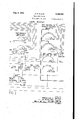
INDICATING SYSTEM Filed April 30, 1942 s ShetS -Sheet 1 SENDING STATION CONTROL MECHANISM lo: 102 I03 I04 :05 v
' CHECKING INDICATOR PANEL led l4 mmcmoak? 2 RESTORING a KEY I40 W PEN . RECORDR INDICATOR "E i PASS KEY I CALLING DEVICE I u4 +fi |24 133 I64 |25L I345. I462. LAMP 1 fl;
GAELL BACK I65 LAM$G1 F 1 INVENTOR.
BERNARD D. WlLLlS, DECEASED BY WM WALTER OWEN, EXEGUTOR INDICATING' SYSTEM Filed April 30; 1942 3 Sheets-Sheet 2 CONTROL MECHANISM DIGIT SEQUENCE 8! INDICATOR SELECTING SWITCH 250,
men SEQUENCE swncu 20o REG. 00m. CIR
p TEST REPEATING- R220 223 INVENTOR.
BERNARD D. WILLIS, DECEASED BY WM. WALTER OWEN, EXEgUTOR I av 9%, W
ATTORNEYS Aug. 8, 1944.
CONTROL MECHANISM B. D. WILLIS INDICATING SYSTEM Filed'April 30, .1942 3 Sheets-Sheet 3 RECEIVING STATION l (i (J I 11121211308U32 U235 4 m [7- E ri l INDICATOR GROUP 300 INDICATOR GROUP 350 INDICATOR com.
cmcun 31 0 7 I F 34! /342 INDICATOR RESTORING 5 KEY 340 am PULSEL GENERATOR 'CALL BACK n 5 INVENTOR. BERNARD D. WILLIS, DECEASED BY WM. WALTER 0 EN, EXECUTOR W-ZmkxrM BY e ATTORNFYQ Patented Aug. 8, 1944 INDICATING SYSTEM Bernard D. Willis, deceased, late of Oak Park, 111.,
by Wm. Walter Owen, executor, Elgin, 111., assignor to Automatic Electric Laboratories, Inc., a corporation of Delaware Application April 30, 1942, Serial No. 441,113
3 Claims.
The present invention relates to indicating systems and, more particularly, to, improvements in systems for transmitting information received at one point to a remote point for visual display thereat.
It is an object of the present invention to provide a system of the character described which is simple in arrangement, includes facilities for posting several different items of information, utilizes a minimum of equipment, and is positive and reliable in operation. 1
It is another object of the invention to pro vide in a system of the character described, a single automatically controlled switch which may be of any desired type and is controlled to operate as a digitsequence switch for directing the impulses of successive digits to different indicators and also to select'an idle group of indicators from a plurality of groups'of indicators associated therewith.
The improved indicating system, as described with particularity below, is of particular utility in transmitting information to the flight observation point of an airplane dispatching or observing organization. A large map may be provided at this point for indicating the location of planes flying within agiven area. Observers variously located throughout this area may, by using telephone or other communication facilities, transmit to a central operator descriptions of planes observed within the area and the directions of flight of the observed planes. The operator, upon receiving this information, may utilize the improved system as herein disclosed to transmit the received information to the flight observation point.
The invention, both as to its organization and method of operation, together with further objects and advantages thereof, will best be understood by reference to the specification taken in connection with the accompanying drawings in which Figs. 1, 2 and 3, when placed side by side in the order named, illustrate a system characterized by the features of the present invention.
Referring now more particularly to the drawings, the systemthere illustrated comprises a display board which is provided with a plurality of groups of indicators 300,350, etc. This display board is provided at a receiving station or observation point in the view of an attendant who, upon receiving the information set up in any group of indicators, may record the received information upon a map, or chart, and. then release the particular indicator group displaying the-information. Fiveindicators are pro vided in each of the several indicator groups. For example, the indicator group 300 comprises the five indicators 30], 302, 3%, 304 and 385 which may respectively be operated by the received impulses of the ten thousands, thousands, hundreds, tens and units digits of a five digit code number utilized to set these indicators so that theydisplay a desired indication. Each of these indicators is of the Well-known electro-mechanical type and is provided with a display board drum which may be rotated from a normal or blank position to any one of ten cit-normal positions wherein the numerals 1 to 9 and 0 are respectively displayed thereby. The indicating drum of each indicator is mounted on a drive shaft to which rotary movement is imparted in one direction only by a pulse-controlled operating magnet and an associated ratchet and pawl or' Geneva gear mechanism. The drive shaft of each register also carries a cam which is arranged to control an associated set of commutating contacts in the manner-more fully explained hereinafter. If desired, the various indicators may be of the construction disclosed in Fig. 22 of Patent No. 2,234,684, granted March 11, 1941, Martin L. Nelson and Harold C. Robinson.
Each group'of indicators has associated therewith an indicator control circuit which is utilized primarily to effect the release of the indicators in the associated group. For example, the indicator group 309 has associated therewith a control circuit 310' which is illustrated as comprising a connect relay R310, a start restoring relay R 38U,=and an off-normal relay R390. Thesejthree relays are arranged to be controlled by an indicator restoringkey 346 which is also individual to the indicator group 35!!) and is provided at the receiving station. Itwill be under-stood that similar control circuits and restoring keys individual to the other indicator groups provided at the receiving station are also included in the system. A call back key 365 islalso provided at the receiving station for en- .abling the attendant at this station to signal the operator at the distant sending station that verification of a received item of information is required. p Y
The selective control of the indicators in the variousgroups is effected from a remote point at which the information to be posted on the dis- .play boardis received. This remote point is illustrated as. comprising a sending station at which is. provided the equipmentrshown to the left of the vertical dash-line appearing in 1 ceiving station, a pen recorder I'I-I may also be provided at the sending station. 'Ihe checking indicator panel I80 includes five electro-mechani cal indicators IIII, I02, I03, I04 andI'05 which are identical in construction and arrangement with those provided on the display board located at the receiving station. It is provided for the purpose of permitting the operator at the sending station to verify any given piece of information transmitted to the receiving station by observing the transmitted code number designating the item of information as this code number is set up in the checking panel;
As indicated above; the transmission of information from the sending station to the receiving station is effected by using definitely coded sets of impulses in digit form to control the indicators of a selected group asprovided on the display board at the receiving station. The automatic switching equipment illustrated in Figs. 1 and 2 of the drawings is arranged to be controlled by the calling device I60 to select the different groups of indicators which are to receive thecode numbers designating the different items of information, and to direct the, coded digits ofany particular code number to the appropriate indicators of the selected group.. This equipment comprises a digit sequence and indicator selecting switch 250 of the well-knownrotary type, and a groupof control relays. More specifically considered, the rotary switch 250 comprises four sets of contacts of twenty-five points each, wipers ZEI, 25I, 253 and 254 individually associated with the four contact sets, and, an operating magnet 255 which, in combination. with an associated ratchet and pawl mechanism, is arranged to drive the enumerated Wipers over the contacts of their associated contact sets. In brief, the relay. equipment includes a fast-acting pulsing relay RI II], three slow-to-release digit relays RIZI], RI3IJ and RI45, a pulse repeating relay RZllll, a test relay R220, and a stepping relay R230. The enumerated relays are also arranged to control the indicators .Of the checking panel I during the transmission of the digits of each code number. Inorder to direct the different digitsof a transmitted code number successively to the different indicators of the checking panel I60, a digit sequence switch 200 is provided. This switch is of the well-known minor type, comprising, two sets of contacts of, eleven points each, Wipers 20I and 202 individual to the two contact sets, an operatingmagnet 204 for driving the two wipers over the contacts of their associated contact sets, and a release magnet 203 which,
storing relays RIIll and RIBO are provided.
These two relays, like the release magnet 2 03 of the sequence switch 200, are arranged to be controlled by the indicator restoring key. I40. For
the purpose of restoring to normal the indicators provided in the checking panel I00 and on the display board located at the receiving station, a pulse generator 3I I common to all of the indicators is provided. This generator, which is only schematically shown, may be of any desired commercial structure although preferably is of the motor-driven commutator type;
Current for energizing the indicator operating magnets, the control relays, the signal lamps, and the operating magnets of the rotary and minor switches, is supplied from a common direct current source, the positive terminal of which is connected to a common bus conductor and to ground. The negative terminal of the source is connected to a common negative bus conductor which terminates the various relay, magnet and lamp terminals identified in the drawings by the negative polarity sign. For convenience in describing the circuits involved, this source of current, which may conventionally comprise a storage battery floated across the terminals of a charging rectifier, has not been shown.
. In considering the operation of the system, it may be assumed that the operator at the sending station receives an item of information which is to be transmitted to the receiving station at a time when all of the equipment provided in the system is at normal. It may be assumed further that the wipers of the digit sequence and indicator selecting switch 25!) occupy the positions i1- lustrated in the drawings. In such case, a circuit is completed through the wiper 254 and the contacts 224 and I35 for energizing the go signal lamp I64. Theillumination of this lamp serves to advise the operator at the sending station that the automatic switching equipment is at normal and that one of the groups of indicators of the display board located at the receiving station has been selected to receive the digits of the code number designating the particular item of information to be transmitted. More specifically, with the wipers of the switch 250 engaging their respective associated first contacts, the illustrated indicators of the group 300 are preselected to receive the digits of the code number. For explanatory purposes, it may be assumed that the code number assigned to the particular received item of information is the number In order to post the code number identifying the particular item'of received information on the display board at the receiving station, the operator at the sending station repeatedly actuates the calling device I69 to dial the different digits of this number. When the dial of this device is first moved off normal, the off-normal springs. I62 and I 63 are closed to complete a circuit through the pulsing contacts IBI for'ene'rgizing the two windings of the pulsing relay RLI I0 in series. In operating, the relay RI I0 closes its contacts II3 to complete an obvious circuitlfo'r energizing the slow-to-release' digit reIay RQIZD. At its contacts II2, the relay RI Ill opens a point in the operating circuit for the digit relay RI30. At its contacts In and ml, the rela aria pie, pares a circuit for energizing thepulserepeating relay Rzillinseries with the operating-magnet 3660f the indicator Bill -in the selecteddhdicator group 339. The digit-relay RI 20, upon operating, closes its contacts I23 to prepare the-operating circuit for the digit relay RUB.- At itscontacts .IZI, the relayRI2il opens a, point-inthecircuit for energizingthe operating -rnagnet zlltl of the d it equ nc switch .20."- ji cont in I?! the relay RI20 opens a point in the circuit for energizing the operating magnet 255 of the rotary switch 250. At its contacts l24, the relay RI29 further prepares the above-mentioned circuit for energizing the pulse repeating relay R2 I in series with the operating magnet 306 of the indicator 30I. At its contacts I25, the relay RI20 opens a point in the operating circuit for the test relay R220. During the dial return movement of the calling device I60, the pulsing contacts I-6I are opened and closed four times to transmit four impulses to the pulsing relay RI III. This relay, in releasing at the beginning of the open-circuit period of the first impulse, opens its contacts I I3 to interrupt the operating circuit for the digit relay RI20, and closes its contactsl I2 to complete the prepared operating circuit for the digit relay RI30. At its contacts III and II i,'the relay RI it opens the prepared circuit for energizing the pulse repeating relay R2 I 0 in series with the operating magnet 306 of the indicator 30 I. The digit relay RI30, upon operating, closes its contacts I3I to prepare the circuit for energizing the operating magnet 234. At its contacts I32, the relay Rl30 similarly prepares a circuit for energizing the operating magnet 255. At its contacts I33, the relay R530 further prepares the circuit for energizing the pulse repeating relay R2 I 0 in series with the operating magnet 306 oi the indicator 30i. At its contacts I34, the relay RI30 opens a point in the operating circuit for the test relay R220. At its contacts I35, the relay RI30 opens the circuit for energizing the go signal lamp I60. When deenergized, this lamp indicates that the associated automatic switching equipment is busy. At its contacts I36, the relay RI30 completes an obvious circuit for energizingiherelay RME. In operating, the relay RME opens its contacts I46 further to interrupt the operating circuit for the relay R220. 7
When the pulsing relay RI I0 reoperates at the end of the open-circuit period of the first impulse, it closes its contacts M3 to recornplete the oper-.
ating circuit for the digit relay RI20, and opens its contacts I I2 to interrupt the operating circuit for the digit relay RI30. At its contacts I I I and I I0, the relay RI l0 completes the prepared circuit for energizing the pulse repeating relay R2I0 in series with the operating magnet 306 of the indicator 30L way of the contacts III, the Wiper 25I and its engaged first contact, the contact springs 301, the winding of the magnet 306, the wiper 252 and its engaged first contact, the winding of R2I0, the
contacts I33, I24 and H4, and the resistor I25 to the negative terminal of the current source.
When thus energized themagnet-306 operates to. rotate the associated display drum from its normal position to a position'when thenumeral ll is displayed through the window of the indicator 30!. Incident to the off-normal movement of this display drum,'the contact springs 308'are moved into engagement to complete an alternative circuit for energizing the pulse repeating relay Rfllfl and the magnet 306 in series with the operating winding of the off-normal relay R390. This circuit extends from ground by way of the operating winding of the relay R390, the contact springs 308, the winding'of themagnet 306, the wiper 252 and its engaged first contact, the wind-.- ing of RZIEI, the contacts I33, I24 and "H4, and the resistor I20 to the negativeterminal of the current'sourcej. After thiscircuit is"completed, the contact Springs 301 are disengag'd toopen the This circuit extends from groundby initially completed circuit energizing the relay R2I0 and the magnet 306 in series. When energized in the above-traced circuit, the relay R390 locks up in a circuit which includes its holding winding and the contacts 39I and 38L At its contacts 333, the relay R390 disconnects the marking lead 390, which is individual to the indicator group 300, from ground. At its contacts 302, the relay R390 completes a path including the resistor 395 for impressing the negative potential of the current source upon the marking lead 304. I. The change in potential on the marking lead 394 serves to mark the indicator group 300 as busy in the contact set of the rotary switch 250 over which the test relay R220 is controlled in the manner explained below.
The pulse repeating relay R21 0, upon operating in response to the reoperation of the pulsing relay RI I0, closes its contacts 2I3 to transmit a ground pulse to the pen recorder III, whereby the impulse as transmitted to the indicator 30I is recorded.- At its contacts 2H and 2I2, the relay R2I0 completes a circuit for energizing the operating magnet I06 of the ten thousands indicator IOI provided in the checking panel I00. This circuit extends from ground by way of the contacts 2I I, the wiper 20I and its engaged first contact, the contact springs I01, the winding of the magnet I06, the wiper 202 and its engaged first contact, the contacts 2I2 and the resistor 2I4 to the negative terminal of the current source. When thus energized the magnet I06'actuates the associated display drum one step from the normal position thereof so'that the numeral 1 is displayed through the Window of the indi-' cator IOI. Incident to the off-normal movement of this drum, the contact'springs I08 are closed to complete an'alternative circuit for energizing the magnet I06, after which the contact springs I01 are opened to interrupt the initially completed circuit for energizing this magnet. The indicated alternative circuit is more direct and extends from ground by way of the contact springs I08, the winding of the magnet I06, the wiper 202 and its engaged first contact, the contacts 2I2, and the resistor 2| 4 to the negative terminal of the current source.
Whenthe pulsing relay RIIO again releases during the open-circuitperiod of the second impulse, it opens the operating circuit for the digit relay RI20, recloses the operating circuit for the digit relay RI30 and, at its contacts H4, deene'rgizes the series-connected windings of the pulse repeating relay R2 I 0 and the magnet 306. In releasing, the relay R2I0 opens its contacts2I3 'to deenergize the operating magnet of the pen recorder IT! and, at its contacts2l2, deenergizes' the magnet I06 of the first indicator IOI." The manner in which the second, third andfourth impulses are repeated by the pulsing relay'RI I0 and the pulse repeating relay R2I0 to the operating magnets 306 and I06 of the indicators 30I and IOI, and by the relay R2I0 tothe pen recorder III, will be readily apparent in view of the above explanation. At th end of the digit'the display drums of the two indicators IOI and 30I are each operated to a position wherein the numeral 4 is displayed'thereby. In this regard it will be noted that during the impulse repeating operation the operating circuits for the two digit relays RI 30 and RI 20 are alternately opened and closed at the contacts I I2 and I I3 by the pulsing, relay RI I0. Due to the slow-to-release charac teristics thereof, the two relaysRI20 and RI30 remain operated during each digit dialed at the sending station. 7 I
Shortly following the end of the first digit, the relays RIIO and RI 20 sequentially restore. In releasing, the relay RI20 opens its contacts I24 to interrupt the. circuit, for energizing the pulse repeating relay R2I0 in series with the magnets of the indicators in the selected group, and closes its contacts I25 to prepare the operating circuit for thetest relay R220. At its contacts, I23, the relay RI20 deenergizes the digit relay RI30. At its contacts I2I, the relay RII20 completes a circuit through the contacts I3I for energizing the operating magnet 204 of the digit sequence switch 200. At its contacts I22, the relay RI20 completes a circuit through the contacts I32. for energizing the operating magnet 255 of the digit sequence switch 250. When thus energized, the magnet 204 operates to advance the wipers 20I and 202 out of engagement with their associated first contacts and into engagement with their associated second contacts, whereby the circuit for transmitting current pulses to the magnet I06 of the first indicator Ilfll is broken and the circuit for energizing the operating magnet of the second indicator I02 is prepared. Shortly following the release of the relay RI20, the digit relay RI30 restores and opens its contacts I3I to deenergize the magnet 204.. At its contacts I32, the relay RI30 deenergize the magnet 255. At its contacts I36, the relay RI30 deenergizes the relay RI45. At its contacts I34, the relay RI30 further prepares the operating circuitfor the test relay R220.' At its contacts I35, the relay RI30 prepares the circuit for energizing the go signallamp I64.
- The magnet 255, upon releasing, advances the wipers 25I, 252,253 and 254 out of engagement with their associated first contacts and into engagement with their associated second contacts, whereby the operating circuit for the magnet 306 of the first indicator 30I is opened and a circuit is prepared for transmitting current pulses to the Operating magnet of the second indicator 302. Shortly after the wipers of the switch 250 are stepped to engage their associated second contacts, the relay RI45 releases and closes its contacts I40 further'to prepare the operating ciredit for the test relay R220.
The manner in which the five impulses of the second digit are repeated to the operating magnets of the two indicators 202 and 302 and to the pen recorder'II'I, will be clearly apparent from the above explanation. It will be understood from this explanation that the three relays R5120, RI30 and RI45 are reoperated at the'b'eginning oithe second digit and remain operated until the digit is ended. It will also be understood that at the end of the digit the indicating drums of the two'indicators I 02 and 302 are operated to offnormal positions wherein'the numeral is displayed thereby. At the end ofthe' digit, the relays EHO, RI20, RI3iI and RI45' are sequentially released in thatorder, whereby the wipers 'of the two sequence switches ZIid and 250 are stepped a second step. Incident to this stepping operation,ithe pulsing" circuit controlledby the pulse repeating jrelay R2! is transferred to include the operating magnet of the indicator I03,
and thepulsing circuit controlled by the pulsing indicators )3, I04-and I05 oi the checking panel I00 and to the indicators 303, 304 and 305 of the indicator group 300 in a manner which will be clearly apparent from the preceding explanation. In this regard it will be understood that at the end of the dialing operation the code number 45678 is posted in the checking indicator panel I00 and in the indicator group 300. This number as interpreted by the attendant at the receiving station indicates the specific item of information received by the operator at the sending station. The code number as posted in the checking panel I00 permits the operator at the sending station to verify the code number as it istransmitted to the receiving station. In this regard it is pointed out that if the attendant at the receiving station is in doubt as to the authenticity of the received information, she may ask the operator at the sending station to repeat the transmission of the code number. To this end, the call back key 365 is operated to complete an obvious circuit for energizing the call back signal lamp I05. When this lamp is energized at the sending station, the operator is informed that verification of the transmitted code number is requested.
Incident to the transmission of the last digit of the code number, the dig t sequence and indicator selecting switch 250 is automatically operated to select another group of indicators at the receiveing station in which no code number is posted. In this regard it will be recalled from the preceding explanation that when the display drum of the first. indicator I in the indicator group 300 is operated to an off-normal position, the oilnormal relay R390 associated with this indicator group is locked energized. With this relay operated, the'negative terminal of the current source isconnected to the marking lead 394 to indicate that the indicator group 300 has a code number posted therein. On the other hand, when no code number is posted in the indicator group 300, the off-normal relay R390 is deenergized such that the marking lead 394 is connected to ground through the contacts 393. In a similar manner, the four other marking leads 200, 26L 252 and 263, individual to the four other indicator groups,
indicator group, i. e., that individually associated above, the wipers of the switch 250 are operated to engage their respective associated sixth contacts, and the four relays RIH), RI20, RI30 and RI are sequentially released. With the wiper 253 in this position, the operating circuit for the testrelay R220 is further prepared. This circuit is completed at the contacts I46 in response to the release of the relay RI45, and may be traced as extending from ground by way of the contacts I25, I34 and I46, the winding of R220, the wiper 253 and its engaged sixth contact, and the marking lead 200 to the negative terminal of the ,current source. It will be noted that if the Wiper 253 finds the marking .lead 260 connected to ground, indicating that the associated indicator group is idle, the winding of the test relay R220 is short-circuited over the circuit just traced and does not operate. If energized in this circuit, the relay R220 locks up in a circuit WhlOh mcludes'the contacts HI and 223, and
the resistor 226.
energizing the magnet 255. I This magnet, in 010- crating, opens its contacts 256 to deenergize'the stepping relay R233. In restoring, the relay R230 opens its contacts 23I 'to deenergize the magnet 255; When the magnet 255 is deenergized the wipers of the switch 253 are stepped out of engagement with their associated sixth contacts and into engagement with their associated seventh contacts. Thus the above-traced operating' circuit for the test relay R220 is broken at the wiper 253. The magnet 255, in releasing, also closes its contacts 256 to again energize'the stepping relay R239. This relay, in reoperating,
closes its contacts 23I to again energize the magnet 255. The interrelated operation of the stepping relay R239 and the magnet 255 continues until the wipers of'the switch 253 are advanced to engage their associated eleventh contacts, wherein the marking lead 26!, corresponding to the third group of indicators, is connected to the wiper 253 to complete a test circuit which includes the Winding of the test relay R229. I1 this marking lead is also connected to the negative terminal of the current source, the Winding of the test relay R220 is not deenergized and the stepping operation of the switch 253 continues. On the other hand,,if the third group of indicators is at normal, such that the marking lead 26! is connected to ground, the winding of the test relay R225! is short-circuited. When thus deenergized, the relay R22?! releases and open its contact-$222 to interrupt the operating circuit for the stepping relay R230 and thus prevent the lat-' .ter relay from reoperating to again energize the cult. At-its contacts 224, the relay R220 recom- I pletes the circuit for energizing the go signal lamp I 64, this circuit now extending from ground by way of the wiper 254 and its associated-eleventh contact, the contacts 224 and I 35, and the filament of the lamp I34 to the negative terminal of the current source. Following the release of the test relay R220, the third group of indicators is selected through the wipers of the switch 253 for use in posting the digits of the code number next dialed by the operator at the sending station.
From theiabove explanation it will be understood that shortly follcwing the transmission of a code number to a selected group of indicators at the receiving station, operation of the switch 250 is initiated to search for another group of indicators in which no code number is posted. It will also be apparent that the searching operation continues until an indicator group in whi ch no code number is posted is found. Under oer:
tain'circumstancesthis may entail the opera tion of theiswitch 250 to test several groupsof indicators before an idle group "is found. During started.
If ,for any reason the operator at the sending ingthe restoring relay RIIil.
7 six indicators in the checking panel Ice.
station desires to pass the last portion of the indicators of a selected indicator group after the first indicators of the group have been set to dis-- play a code number, the indicator pass key Idii is momentarily actuated to its off-normal position. When this key is operated'to its oil"-normal position the contact springs I55 are closed to complete a circuit, including the resistor i5 3 and the contacts I25, I 34 and M5, for energizing .the test relay R223. The test relay, upon operating, locks up ina circuit including the contacts 22I and 223 and closes its contacts 222 to initiate the interrelated operation of the stepping relay R230 and the operating magnet 255 in the manner explainedabove. As these two circuit elements interact, the wipers of r the switch 2553 are advanced step by step through the positions corresponding to the unoperated indicators of the selected group and into the position corresponding to the first indicator of the next indicator group. If this next indicator group is busy the searching operation of the switch 255 continues. It is only terminated when the wipers are advanced to the position corresponding to the first indicator of the first available indicator group in which no code number is posted. V
As indicated by the preceding explanation, the checking indicator panel Illil is provided for the purpose of enabling the operator'at the sending station to verify each code number transmitted to the receiving station. It will be understood, therefore, thatthe'indicators of this panel are to be isstored to normal at the end ofeach dialing oper ation. To this 'end, the restoring key Mil is momentarily actuated to its off-normal position immediately after a dialing operation is completed and the'posted code number is checked; Incident to this operation, the contact springs I43 are closed to complete an obvious circuit for energizing the release magnet 29,3. This magnet, inoperating, attracts its associated holding pawl, permitting the spring biased' wipers 2EII and 202 to be'returned'to normal. At the contact springs I, an obvious circuit is completed for energiz This relay, inoperating, closes its contacts III to prepare a looking circuit for itself; At its contacts I72 to H3, inclusive, the relay'RI'Itl prepares a circuit for transmitting restoring pulsesto the operating magnets of each of the five indicators in the checking panel mil. At the contact springs I52 ofthe key I40, a circuit is prepared or completed for energizing the winding of the restoring relay RI8I] 'in series with the operating magnets of the This circuit,- when completed by the pulse generator 3I I, extends from the negative terminal of the current source :by way of the commutating con tacts of the pulse generator 3| I, the winding of RI 80, the contact springs I 32, the contacts Ill. to I16, inclusive, and the parallel-connected windings of the six indicator operating magnets to ground. VVhen' energized in this circuit, the relay RI closes its'contacts IBI to complete the pre} pared locking circuit for the restoring relayRI Iii. At its contacts I82, the relay Rite closes an ob vious'shunt path across the contact springs I 42, thereby to prevent the restoring pulse circuit from being interrupted in response to the release of the key' l lii. With the two relays RI'IQ and RI80 operated, restoring pulses are transmitted from the'pulse generator 3II to the operating magnets of the five indicators 'Ii lI, I52, 33, I
and I05-until'al1'of the display drums of these 'indicatorsihave been driven to their respective normal positions. These pulses are obviously transmitted through the winding of the relay RI80, which relay being of the slow-tb-releas'e type remains operated until the pulsing circuit is broken. In thisregard it is pointed out that when the-indicating drum of each indicatoriis returned to its normal or blank position, the associated cam is operated to break the restoring pulse circuit through the Winding of the associated magnet. Thus when the display drum of the indicator ml is moved to its-normal or blank position, the contact springs 100 are disengaged to interrupt therestoring pulse circuit through the associated magnet I06. Also, the contact springs I01 are moved into engagement to reprepare the circuit, controlled by the pulse repeating relay R2l0, for energizing the magnet I06. It will be understood, therefore, that after the display drums of the five indicators l fill, E02, I03, I04 and I05 have been restored to their normal or blank positions, no further current pulses are transmitted through the winding of the relay RI80. Accordingly, this relay restores. In releasing, the relay R480 opens its contacts I18! to The latter the digits of another code number.
The attendant at the receiving station, in order to restore to normal any particular'groiupof indicators, actuates the associated indicator restoring key. Thus in order to clear the indicator group 300 of the code number set up therein in the manner explained above, the restoring key 340 is momentarily actuated to its off-normal position, wherein the contact springs 34l and 342 are respectively operated into engagement.
At the contact springs 3 an obvious circuit is completed for energizing the connect relay R310. At the contact springs 342, a circuit is prepared for transmitting current pulses through the winding of the restoring relay R380 and the parallel-connected windings of the operating magnets of the indicators in the indicator group 300. The relay R310, upon operating, closes its contacts 31] to prepare a locking circuit for itself. At its contacts 312 to 316, inclusive, the relay R310 completes the circuit for transmitting restoring pulses to the operating magnets of the'indicators in the indicator group 300. These current pulses are transmitted over a circuit which extends from the negative terminal of the current source by way of the commutating contacts of the pulse gener; ator 3| I, the winding of R380, the contactsprings 342, the contacts 31.2 to 316,inclusive, the parallel-connected magnet windings of the indicators in the group 300, and the operating winding of the relay R390 to ground. Whenenergized by the first current pulse transmitted over this circuit, the relay R380 closes its contacts 383 to complete an obvious path in shunt with the contact springs 342 and thus prevent the restoring pulse circuit from being opened until all of the indicators of the group 300 have been restored to normal. At its contacts 38!, the relay R380 opens the locking circuit for the off-normal relay R390. At its contacts 382, the relay R380 completes the prepared locking circuit for the connect relay R310; Each time a restoring pulse is transmitted to the operating magnet of any one of the fivev indicators in the indicator group 300, the magnet operates to advance the associated display drum one step. Accordingly, after a given number of pulses have been transmitted to the magnets of the indicators in this group, the display drums of these indicators are restored to normal. In this regard it is again pointed out that when the display drum of any indicator is moved to its normal or blank position, the associated commutator controlled contact springs are operated to interrupt the restoring pulse circuit. For example, when the display drum of the indicator 30| is returned to normal the contact springs 398 are disengaged to prevent further energization of the magnet 306. Also, the contact springs 301 are moved into engagement to prepare a pulsing circuit over which impulses may be transmitted to this magnet under the control of the pulsing relay RI l0. After all of the indicators in the group 300 are restored to normal, no further circuit is available for energizing the operating winding of the oil-normal relay R390 or the winding of the restoring relay R380. Accordingly, these two relays release in the order named, The relay R380, upon restoring, opens its contacts 382 to deenergize the connect relay R310. Following the restoration of the latter relaythe indicator control circuit 3l0 individual to the indicator group 300 is fully restored to normal. 7
While one embodiment of the invention has been disclosed, it will be understood that various modifications may be made therein which are Within the true spirit and scope of the invention.
What is claimed is:
'1. An indicating system comprising a plurality of groups of individual multi-positioned character'indicating means, means whereby each indicating means is moved to its different positions indicating its characters by a series of successive impulses, the number of which corresponds to the character to be indicated, impulsing means :'for transmitting series of impulses, the number in each series being indicative of the character represented by said series, a multi-position sequence switch having a position for each indicating means through which the impulses for operating it are routed, means for advancing the sequence switch from position to position, means operated at the termination of each series of impulses for operating the advancing means to advance the sequence switch to the next position, and means operated When the sequence switch encounters a group of indicators in which an indication is setup for operating the advancing means to move the sequence switch from position to position for said group until it moves to a position corresponding to the first indicating means of the next group.
2; An indicating system comprising a plurality of groups of individual multi-position character indicating means, means'whereby each indicating means is moved to its diiTerent positions indicating its characters by a series of successive impulses, the number of which corresponds to the character to be indicated, impulsing means for transmitting series of impulses, the number in each series being indicative of the character represented by said series, a multi-position sequence switch having a position for each indicating means through which the impulses for operating it are routed, means for advancing the sequence switch from position to position, means operated at the termination of each series of impulses for operating the advancing means to advance the sequence switch to the next position and means operated when the sequence switch encounters a group of indicators in which an indication is set up for operating the advancing means to move the sequence switch from position to position for said group until it moves to a position corresponding to the first indicating means of the next group, said last means including a test device controlled by said switch and operative to determine whether or not an indication is posted in a group of indicators when said switch is operated to the setting corresponding to the first indicator of the group.
3. An indicating system comprising a plurality of groups of individual multi-position character indicating means, means whereby each indicating means is moved to its diiferent positions indicating its characters by a series of successive impulses, the number of which corresponds to the character to be indicated, impulsing means for transmitting series of impulses, the number in each series being indicative of the character represented by said series, a multi-position sequence switch having a position for each indicating means through which the impulses for operating it are routed, means for advancing the sequence switch from position to position, means operated at the termination of each series of impulses for operating the advancing means to advance tion to position for said group until it moves to a position corresponding to the first indicating 'means of the next group, said last means including a test device controlled by said switch and operative to determine whether or not an indication is posted in a group of indicators when said switch is operated to the setting corresponding to the first indicator of the group and means controlled by said test device for automatically advancing said switch through the settings corresponding to the indicators of a group in which an indication is posted.
WM. WALTER OWEN, Executor of the Estate of Bernard D. Willis, De-
ceased.
Priority Applications (1)
| Application Number | Priority Date | Filing Date | Title |
|---|---|---|---|
| US441118A US2355352A (en) | 1942-04-30 | 1942-04-30 | Indicating system |
Applications Claiming Priority (1)
| Application Number | Priority Date | Filing Date | Title |
|---|---|---|---|
| US441118A US2355352A (en) | 1942-04-30 | 1942-04-30 | Indicating system |
Publications (1)
| Publication Number | Publication Date |
|---|---|
| US2355352A true US2355352A (en) | 1944-08-08 |
Family
ID=23751593
Family Applications (1)
| Application Number | Title | Priority Date | Filing Date |
|---|---|---|---|
| US441118A Expired - Lifetime US2355352A (en) | 1942-04-30 | 1942-04-30 | Indicating system |
Country Status (1)
| Country | Link |
|---|---|
| US (1) | US2355352A (en) |
Cited By (3)
| Publication number | Priority date | Publication date | Assignee | Title |
|---|---|---|---|---|
| US2444078A (en) * | 1942-06-10 | 1948-06-29 | Bell Telephone Labor Inc | Trouble alarm system |
| US2482271A (en) * | 1947-09-20 | 1949-09-20 | Teletype Corp | Printing arrangement for merchandising control systems |
| US3051937A (en) * | 1957-04-12 | 1962-08-28 | Arthur James | Message register reader |
-
1942
- 1942-04-30 US US441118A patent/US2355352A/en not_active Expired - Lifetime
Cited By (3)
| Publication number | Priority date | Publication date | Assignee | Title |
|---|---|---|---|---|
| US2444078A (en) * | 1942-06-10 | 1948-06-29 | Bell Telephone Labor Inc | Trouble alarm system |
| US2482271A (en) * | 1947-09-20 | 1949-09-20 | Teletype Corp | Printing arrangement for merchandising control systems |
| US3051937A (en) * | 1957-04-12 | 1962-08-28 | Arthur James | Message register reader |
Similar Documents
| Publication | Publication Date | Title |
|---|---|---|
| US2139079A (en) | Code translator | |
| US2335524A (en) | Signaling system | |
| US2248820A (en) | Electrical indicating means | |
| US2355352A (en) | Indicating system | |
| US1709031A (en) | Supervisory control system | |
| US2074423A (en) | Selecting system | |
| US2071184A (en) | Indicating system | |
| US1676742A (en) | Traffic-recording equipment for telephone systems | |
| US2053749A (en) | Transmitter for stock quotation boards | |
| US1852994A (en) | Signaling apparatus and method | |
| US1945470A (en) | Signal transmitting apparatus | |
| US1986972A (en) | Selecting system | |
| US2474438A (en) | Communication and posting system | |
| US2330355A (en) | Indicating system | |
| US2934745A (en) | Remote frequency selection system | |
| US1798128A (en) | Power-dispatching system | |
| US2136672A (en) | Electrical transmitting mechanism and circuit | |
| US1960779A (en) | Selective signaling system | |
| US2330357A (en) | Signaling system | |
| US2052539A (en) | Electrical indicating apparatus | |
| US1890878A (en) | Electrical indicating system | |
| US1980190A (en) | Impulse transmitter | |
| US2330358A (en) | Indicating system | |
| US2135794A (en) | Remote control system | |
| US1880722A (en) | Call distributing system for concentration circuits |