US2288332A - Dispensing cabinet and method of servicing - Google Patents
Dispensing cabinet and method of servicing Download PDFInfo
- Publication number
- US2288332A US2288332A US32290040A US2288332A US 2288332 A US2288332 A US 2288332A US 32290040 A US32290040 A US 32290040A US 2288332 A US2288332 A US 2288332A
- Authority
- US
- United States
- Prior art keywords
- roll
- cabinet
- paper
- servicing
- rolls
- Prior art date
- Legal status (The legal status is an assumption and is not a legal conclusion. Google has not performed a legal analysis and makes no representation as to the accuracy of the status listed.)
- Expired - Lifetime
Links
Images

Classifications
-
- A—HUMAN NECESSITIES
- A47—FURNITURE; DOMESTIC ARTICLES OR APPLIANCES; COFFEE MILLS; SPICE MILLS; SUCTION CLEANERS IN GENERAL
- A47K—SANITARY EQUIPMENT NOT OTHERWISE PROVIDED FOR; TOILET ACCESSORIES
- A47K10/00—Body-drying implements; Toilet paper; Holders therefor
- A47K10/16—Paper towels; Toilet paper; Holders therefor
- A47K10/18—Holders; Receptacles
- A47K10/22—Holders; Receptacles for rolled-up webs
-
- A—HUMAN NECESSITIES
- A47—FURNITURE; DOMESTIC ARTICLES OR APPLIANCES; COFFEE MILLS; SPICE MILLS; SUCTION CLEANERS IN GENERAL
- A47K—SANITARY EQUIPMENT NOT OTHERWISE PROVIDED FOR; TOILET ACCESSORIES
- A47K10/00—Body-drying implements; Toilet paper; Holders therefor
- A47K10/24—Towel dispensers, e.g. for piled-up or folded textile towels; Toilet-paper dispensers; Dispensers for piled-up or folded textile towels provided or not with devices for taking-up soiled towels as far as not mechanically driven
- A47K10/32—Dispensers for paper towels or toilet-paper
- A47K10/34—Dispensers for paper towels or toilet-paper dispensing from a web, e.g. with mechanical dispensing means
- A47K10/36—Dispensers for paper towels or toilet-paper dispensing from a web, e.g. with mechanical dispensing means with mechanical dispensing, roll switching or cutting devices
- A47K10/3631—The cutting devices being driven manually
- A47K10/3643—The cutting devices being driven manually by pulling the paper
-
- A—HUMAN NECESSITIES
- A47—FURNITURE; DOMESTIC ARTICLES OR APPLIANCES; COFFEE MILLS; SPICE MILLS; SUCTION CLEANERS IN GENERAL
- A47K—SANITARY EQUIPMENT NOT OTHERWISE PROVIDED FOR; TOILET ACCESSORIES
- A47K10/00—Body-drying implements; Toilet paper; Holders therefor
- A47K10/24—Towel dispensers, e.g. for piled-up or folded textile towels; Toilet-paper dispensers; Dispensers for piled-up or folded textile towels provided or not with devices for taking-up soiled towels as far as not mechanically driven
- A47K10/32—Dispensers for paper towels or toilet-paper
- A47K2010/3246—Locking mechanisms for the housing
-
- A—HUMAN NECESSITIES
- A47—FURNITURE; DOMESTIC ARTICLES OR APPLIANCES; COFFEE MILLS; SPICE MILLS; SUCTION CLEANERS IN GENERAL
- A47K—SANITARY EQUIPMENT NOT OTHERWISE PROVIDED FOR; TOILET ACCESSORIES
- A47K10/00—Body-drying implements; Toilet paper; Holders therefor
- A47K10/24—Towel dispensers, e.g. for piled-up or folded textile towels; Toilet-paper dispensers; Dispensers for piled-up or folded textile towels provided or not with devices for taking-up soiled towels as far as not mechanically driven
- A47K10/32—Dispensers for paper towels or toilet-paper
- A47K10/34—Dispensers for paper towels or toilet-paper dispensing from a web, e.g. with mechanical dispensing means
- A47K10/36—Dispensers for paper towels or toilet-paper dispensing from a web, e.g. with mechanical dispensing means with mechanical dispensing, roll switching or cutting devices
- A47K2010/3681—Dispensers for paper towels or toilet-paper dispensing from a web, e.g. with mechanical dispensing means with mechanical dispensing, roll switching or cutting devices characterised by the way a new paper roll is loaded in the dispenser
-
- Y—GENERAL TAGGING OF NEW TECHNOLOGICAL DEVELOPMENTS; GENERAL TAGGING OF CROSS-SECTIONAL TECHNOLOGIES SPANNING OVER SEVERAL SECTIONS OF THE IPC; TECHNICAL SUBJECTS COVERED BY FORMER USPC CROSS-REFERENCE ART COLLECTIONS [XRACs] AND DIGESTS
- Y10—TECHNICAL SUBJECTS COVERED BY FORMER USPC
- Y10T—TECHNICAL SUBJECTS COVERED BY FORMER US CLASSIFICATION
- Y10T225/00—Severing by tearing or breaking
- Y10T225/20—Severing by manually forcing against fixed edge
- Y10T225/202—With timer-released means for preventing work feed-out
-
- Y—GENERAL TAGGING OF NEW TECHNOLOGICAL DEVELOPMENTS; GENERAL TAGGING OF CROSS-SECTIONAL TECHNOLOGIES SPANNING OVER SEVERAL SECTIONS OF THE IPC; TECHNICAL SUBJECTS COVERED BY FORMER USPC CROSS-REFERENCE ART COLLECTIONS [XRACs] AND DIGESTS
- Y10—TECHNICAL SUBJECTS COVERED BY FORMER USPC
- Y10T—TECHNICAL SUBJECTS COVERED BY FORMER US CLASSIFICATION
- Y10T225/00—Severing by tearing or breaking
- Y10T225/20—Severing by manually forcing against fixed edge
- Y10T225/205—With feed-out of predetermined length from work supply
- Y10T225/207—Including feed-out stop for manually pulled work
- Y10T225/209—With feed-out of lead-end to aid initial grasping
-
- Y—GENERAL TAGGING OF NEW TECHNOLOGICAL DEVELOPMENTS; GENERAL TAGGING OF CROSS-SECTIONAL TECHNOLOGIES SPANNING OVER SEVERAL SECTIONS OF THE IPC; TECHNICAL SUBJECTS COVERED BY FORMER USPC CROSS-REFERENCE ART COLLECTIONS [XRACs] AND DIGESTS
- Y10—TECHNICAL SUBJECTS COVERED BY FORMER USPC
- Y10T—TECHNICAL SUBJECTS COVERED BY FORMER US CLASSIFICATION
- Y10T225/00—Severing by tearing or breaking
- Y10T225/20—Severing by manually forcing against fixed edge
- Y10T225/238—With housing for work supply
- Y10T225/246—Including special support for wound supply package
Definitions
- An object is to provide a method :and means by which to facilitate the servicing of a cabinet in a specific manner.
- the method feature relates to the placement of the supply roll upon a support outside of the cabinet in a particular position preparatory to servicing.
- the support may be, and preferably is, a door or closure element for the cabinet, and placement is so made that the paper can be upwardly led over the supply roll from that side of said roll which is nearest the operator and then laid upon a yieldable presser roll, whereafter by the grasping aotion of a single hand the paper is pressed between the rolls in a forward and outward direction, the grasping action including the wedging action of the fingers between the presser roll to raise it so that the paper is simultaneously introduced, and thereafter, while the paper is held by the rolls, the supply roll is swung rearwardly over the presser roll to a nal position rearwardly of the rolls, or feeding means.
- a method for servicing the cabinet in a specific manner includes: a cabinet composed of two sections, one a door cover section movable on the other to such a position that it serves for support for the supply roll when servicing the cabinet; the use of a tear-off knife as a stop to limit the cover section at a shelf-forming position; the particular placement of the supply roll for servicing; the specific construction of the delivery throat or opening as formed by parts of the two relatively movable sections of the cabinet, wherein one element of the inner section is bent upwardly and the lower portion of the outer section is bent outwardly and downwardly to form a tear-off knife; the arrangement of a presser roll so that the paper can be laid against it in a predetermined manner preparatory to servicing; the reduction of the diameter of the presser roll at one point to facilitate introduction of the paper by the fingers between the presser roll and the measuring roll.
- FIG. 1 is a front view of the cabinet with the parts broken away to illustrate constructions of the interior
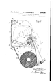
- Figure 2 is a vertical transverse section on line 2 2 of Figure 1 illustrating the method of servicing the cabinet when open;
- Figure 3 is a view similar to Figure 2 showing the cabinet closed, and showing how a delivery throat is formed between the cover and the feed rolls when the cover is closed.
- the numeral I indicates the back of the cabinet, and numeral 2 the bottom thereof.
- the bottom and back are formed in one piece, or section, as shown in Figure 2.
- the bottom is pressed outwardly and downwardly to form a depression 3 having a slot 4.
- the slots are so positioned that dust or dirt rolls downwardly and outwardly through the slots.
- the depressed portion 3 is elongated, in a direction transverse of the cabinet or parallel with the axis of rotation of the feed rolls and the supply roll.
- a forward portion of the bottom 2 is bent upwardly -as at 6, so that its upper edge is arranged close to a feed roll I suitably journaled on an axis or shaft or trunnions 8 in a manner to be hereinafter described.
- This feed roll is grooved as at 9, and the upwardly, outwardly slanted portion 6 has attached thereunto suitable fingers Il] which cooperate with the groove to direct the paper downwardly and outwardly.
- the upper edge of the back has an inturned or forwardly directed horizontal fiange I5, which in turn has at its forward edge downwardly turned flanges I6 spaced apart to provide an opening II.
- a lock generally indicated at I9 has an arm I8 having a hook-end (not shown) which engages the keeper to secure the cover in closed position.
- the locking mechanism is not described because it is of well known construction, but it will be understood when the key is inserted in the lock and the lock is rotated, the arm I8 is swung from the position shown in Figure 3, for example, to a release position which allows the front cover to be swung forwardly and downwardly below the bottom 2 to act as a shelf (see Figure 2).
- the front cover is substantially formed of three which has been shown (see Figure l), arranged-V one at each side of a pair of upright journalingplates later to be described, said brackets being indicated by numerals 25.
- Each bracket rests on the top of a 'flange of aV corresponding feed roll journaling plate and each hasan upturned outer portion through which passes a' pivoting pin 25, one pin being attached to the side 23 and the other to the side 24.
- a split key 21 secures the pin 26 againstl outward movement.
- the pins are introduced into openings of the brackets from opposite sides by movement toward one another after the sides of the device have'breen preliminarily sprung outwardly. The straightening of the previously sprung sides 23, 24 tends to hold the pins inposition.
- This assembly scheme is a feature.
- the strains are transmitted to a region of the bottom which is stiffened by the flange 5I.' It can be seen that the strains on the fulcruming pivots, and in turn on thg rear and bottom walls Iof the inner section, are considerable, particularly when the outer section is loaded with thesupply 35, and particularly when this supply is thrown bythe service man into th'eposition shown.
- FIG. l and 2 Another and important feature of the invention, which is best shown in Figures l and 2, is the arrangement of a tear-off knife to form a downwardly, forwardly extending part of the bottom of the front wall 22 of the cover. This extension is indicated at 3, and it has papersighting openings 29 therein.
- the front 22 of the cover or outer section and the upturned part 6 of the bottom of the case form a throat 3
- the front 22 is bent to provide a bead 32 around which the paperV passes to a point beneath the knife.
- the bead 32 constitutes means for holding the projecting end of the paper, remaining after tear-off, away from the knife so that the ngersor thumb can be introduced between the inner side of the knife and the paper, for grasping the paper to pull out more of it.
- the terminal extension 39 of the bottom of the front wall of the cover or outer casing is so arranged inA relation to the pivots 26 and to the bottom 2 of the cabinet as to form a stop for the cover to limit it as shown in Figure 2 in the proper position to form a, shelf for receiving the paper supply 35 during servicing.
- the extension 33 slants outwardly and downwardly and the front of the cover forms with the elements t and Iii a throat downwardly through which the paper is projected from the feeding means to be engaged by the bead 32 and held in spaced relation to the rear face of the extension 3d to facilitate introduction of the ngers back of said extension for grasping the paper.
- the paper is, after tear-olf, made inaccessible to the user. It is a particular feature of this invention to so arrange the paper with reference to the knife and with reference to the delivery opening that after the paper has been torn off, the paper is still accessible for grasping, although it may be invisible. Another feature is that the knife projects forwardly in plain'viewV so that all one has to dois to reach under it, for example, by introducing the thumb'of one hand between the rear surface of the knife and the paper, so that the remaining iingers'of that hand lie rearwardly of the paper, whereafter the paper can'be grasped and pulled.
- the supply roll 35 is so supported that it simultaneously rests upon the feed roll 1 and upon supporting means, specifically upon a pair of supports, each indicatedby the numeral 36.
- the cross sectionally L-shaped supports are held by a single fastening device indicated at 3?. Due to the inclination of the ledges or movable supports 36, the paper tends to roll constantly toward the feed roll l, no matter how small the roll becomes.
- This construction includes two upright plates respectively indicated at 39, 42': It is to the inner sides of these plates that the inclined supports 36 vare attached and it is between these plates that the supply and feed rolls are disposed.
- Each plate (see Figure l) has at each of threev margins an outwardly directed flangethe fianges pointing toward the sides 23 and 24' of the' cabinet.
- the top flangesfor the0 plates are respectively indicated at 44, 45 and these flanges are cross-connected by a bar 46 held by suitable screws 41.
- the rear flanges are indicated at 50 and the bottom flanges are indicated at The bottom flanges 5
- Key-hole slots 52 are provided in the rear wall so that the cabinet can be hung on suitable fastening devices (see Figure 1).
- This flanged and welded structure braces the perpendicularly related vertical and horizontal parts of the inner section and provides an unusually strong cabinet, by the use of a minimum amount of material.
- the feed roll is suitably journaled by means of a shaft 8, and the plates 39, 40 form part of the journaling means, the said shaft or equivalent trunnions passing through bearing collars punched out of the plates 39, 40.
- These plates also have slots 55 in which are journaled a presser roll 56 pressed into engagement with the paper 5l, as best shown in Figure 2.
- Springs 5S suitably secured yieldably hold the roll in the position shown.
- Figure 2 shows the position of the parts when servicing the cabinet.
- the service man leads the paper from the side which is nearest him, upwardly from and over the supply roll, then over and against and around the presser roll. He then passes the forward edge of the paper between the rolls in a forward, outward direction, and then while the paper is clamped by the presser roll against the measuring roll, that is, while the paper is held by the feeding means, he swings the supply roll upwardly and rearwardly over the feed rolls as indicated by dotand-clash lines at U in Figure 2, to a point rearwardly thereof, and in this case onto the inclined supports 36, so that thereafter the paper leads forwardly from the bottom of the supply roll, over the measuring roll and between the feeding rolls.
- This method of servicing is particularly applicable to a type of cabinet shown.
- the feeding means is arranged at the bottom of the cabinet, in fact, very near the bottom of the cabinet, and at the outer or forward side so as to be easily accessible, and in this case so that the supply roll can occupy a large cubical area of the cabinet rearwardly of and partly above the rolls.
- the full supply roll may, and preferably does, extend substantially from the back wall of the cabinet to the front wall of the cabinet, which front wall in this instance is formed by the outer casing section or cover.
- the presser roll may be more forwardly located so that a larger supply can be placed as shown in Figure 3 without any contact between the supply and the presser roll.
- the supports 36 or their equivalent are provided to cause the supply roll to be gravity-urged against the measuring roll if desired, in varying degrees ⁇ It is noted that the paper comes off the bottom of the supply roll and then leads over and around the measuring roll and between that roll and the presser roll, thence downwardly and out at the bottom of the cabinet.
- the presser roll is cut out or reduced in diameter at 65, and this cut-out in the roll for this purpose is claimed in the combination with the rolls placed as they are so that the paper and the hand can be laid on top of the presser roll, and so that the fingers can curve around it and act as wedges to raise the roll and at the same time push the paper between the rolls.
- Another feature of the invention relates to the reduction in diameter of the middle part of the presser roll 56.
- This cut-out portion is indicated at 65.
- Two or three human fingers can be introduced into this reduced portion of the presser roll, the tips of the fingers at this point pressing the paper inwardly toward the meeting point of the roll.
- This is related to the method of servicing. This can be accomplished whether the supply roll is pocketed in the outer casing or cover when open, or after the supply roll has been placed within the cabinet. In either instance and in the method the paper can be preliminarily laid on top of the presser roll and then the fingers can be curved and the paper pressed into the reduced portion with the fingers curved, their tips turn or move the roll to move the paper toward and into the bite or meeting line of the rolls.
- a feed roll operating disk 'l0 Attached at one end of the roll 'i between the plate 40 and the side 24 is a feed roll operating disk 'l0 which projects through slots 1I respectively in the front 22 of the cover, and in a finishing plate 73.
- the plate is suitably secured by fastening devices and it has an outwardly, downwardly bent portion 14 which overlies the tear-off knife 30. It will be understood that this disk is used for starting the paper after tear-off, the paper after tear-off lying against the under side of the knife and being visible only through the sighting openings 29.
- a dispensing cabinet having a measuring roll, a presser roll above and yieldably cooperating with the measuring roll for feeding the paper, means for supporting a supply roll of sheet material in feeding relation with the measuring roll, said presser roll having a central portion of reduced diameter and of sufficient axial extent to receive a plurality of lingers of the human hand, a closure for the cabinet having means adapted when the closure is open to form a support for a supply roll during servicing, the
- relation of said means with said presser roll and its central portion of reduced diameter being such that the material can be brought fromk that side' of the supply roll nearest the user, laid on top of the presser roll and introduced in forward direction between thegmeasuring and presser rolls by grasping action of the hand about the ⁇ central reduced diameter portion of the presser roll.
- a dispensing cabinet comprising, an inner i base section, an outer cover section forming the top and the front of the cabinet, means pivoting the outer section to the inner section, the front Wall of said outer section having terminally' thereof and projecting below the bottom of the cabinet an elongated downwardly, forwardly slanting extension, the pivoting means for the outer section and said extension being so related that the outer section can be swung from closed position downwardly below the cabinet to have its top form a shelf for supporting a supply roll of sheet material, said extension acting as a stop for limiting such swinging movement at such position, and said cabinet having a measuring roll and a yieldable presser roll thereabove, so that when a supply roll is on said shelf material can be brought from that side of the supply roll nearest the user, pulled upwardly and laid on top of the presser roll and then introduced in a forward direction between the measuring and presser rolls by grasping action of the hand about the presser roll, and means for supporting a supply roll of sheet material in feeding relation with the measuring roll.
- a dispensing cabinet of the hang-on-the- Wall type having inner and outer sections of relatively thin sheet metal, the inner section providing rear and bottom Walls and the outer section providing top, side and front walls, a pair f spaced plates Within the inner section, means rigidly securing marginal portions of the plates to the back and bottom of the inner section to strongly reinforce the thin metal of said back and bottom walls against deformation, a dispensing mechanism mounted on and between the plates, means hinging the outer to the inner section and permitting the former to swing from cabinet-closing position to a level below the in ner section to form a shelf, including parts, one rigidly attached to each plate, each sidewall of the outer section having means hingedly en- ⁇ gaged with a corresponding part, said outer section having a portion which engages the bottom wall to limit said section at shelf-forming position, said parts thereby acting to transmit fulcrumming strains to said plates rather than to the bottom wall when said outer section is in shelf-forming position to receive a supply roll of sheet material to be dispense
- a dispensing cabinet of the hang-on-thewall type having inner and outer sections of relatively thin sheet metal, the inner section providing rear and bottom walls and the outer section providing top, side and front Walls, a pair of spaced plates within the inner section each having flanges rigidly secured by their faces respectively to the faces of the rear and bottom Walls to strongly reinforce the thin metal of said back and bottom walls against deformation, a dispensing mechanism mounted on and between the plates, means hinging the outer to the inner section and permitting the former to swing from cabinet-closing position to a level below the inner section to form a shelf, said means including brackets, one rigidly secured to each of the flanges of said plates which are secured to the bottom Wall of the inner section, said outer section having a portion which engages the bottom wall to limit said section at shelf-forming position, said brackets thereby acting to transmit fulcruming strains to said plates rather than to said bottom wall when said outer section is in shelf-forming position to receive a supply roll of sheet material during servicing.
Description
u -UH 2 Sheets-Sheet 1 STEINER ET AL Original Filed lay 24, 1939 DISPENSING CABINETAND METHOD QF SERVIGING June 30, 1942.l
June 30, 1942- F. G. STEINER Erm. 2,283,332
DISPENSING CABINET'AND METHOD OF SERVICING Original Filed May 24, 1939 2 Sheets-Sheet 2 Patented June 30, 1942 DISPENSING CABINET AND METHOU OF SERVICING Frank G. Steiner, Miami Beach, Fla., and Rudolph G. Birr, Lombard, Ill.,
assignors to Steiner Sales Company, Salt Lake City, Utah, a
corporation of Utah Original application May 24, 1939, Serial No. 275,450. Divided and this application March 8, 1940, Serial No. 322,900
4 Claims.
is rugged, and which has a maximum supply capacity with a minimum of cabinet size.
This application is a division of our application Serial No. 275,450 for Dispensing cabinet, filed May 24, 1939, which has matured into Patent Number 2,243,686, issued May 27, 1941.
An object is to provide a method :and means by which to facilitate the servicing of a cabinet in a specific manner. The method feature relates to the placement of the supply roll upon a support outside of the cabinet in a particular position preparatory to servicing. The support may be, and preferably is, a door or closure element for the cabinet, and placement is so made that the paper can be upwardly led over the supply roll from that side of said roll which is nearest the operator and then laid upon a yieldable presser roll, whereafter by the grasping aotion of a single hand the paper is pressed between the rolls in a forward and outward direction, the grasping action including the wedging action of the fingers between the presser roll to raise it so that the paper is simultaneously introduced, and thereafter, while the paper is held by the rolls, the supply roll is swung rearwardly over the presser roll to a nal position rearwardly of the rolls, or feeding means.
Features of the invention includes: A method for servicing the cabinet in a specific manner; a cabinet composed of two sections, one a door cover section movable on the other to such a position that it serves for support for the supply roll when servicing the cabinet; the use of a tear-off knife as a stop to limit the cover section at a shelf-forming position; the particular placement of the supply roll for servicing; the specific construction of the delivery throat or opening as formed by parts of the two relatively movable sections of the cabinet, wherein one element of the inner section is bent upwardly and the lower portion of the outer section is bent outwardly and downwardly to form a tear-off knife; the arrangement of a presser roll so that the paper can be laid against it in a predetermined manner preparatory to servicing; the reduction of the diameter of the presser roll at one point to facilitate introduction of the paper by the fingers between the presser roll and the measuring roll.
Objects, features and advantages of the invention will be pointed out in the description of the drawings forming a part of this invention; and
In the drawings- Figure 1 is a front view of the cabinet with the parts broken away to illustrate constructions of the interior;
Figure 2 is a vertical transverse section on line 2 2 of Figure 1 illustrating the method of servicing the cabinet when open; and
Figure 3 is a view similar to Figure 2 showing the cabinet closed, and showing how a delivery throat is formed between the cover and the feed rolls when the cover is closed.
One of the features of the invention relates to the manner in which the sections of the cabinet are put together and the manner in which they are constructed, In the drawings, the numeral I indicates the back of the cabinet, and numeral 2 the bottom thereof. The bottom and back are formed in one piece, or section, as shown in Figure 2. The bottom is pressed outwardly and downwardly to form a depression 3 having a slot 4. The slots are so positioned that dust or dirt rolls downwardly and outwardly through the slots. The depressed portion 3 is elongated, in a direction transverse of the cabinet or parallel with the axis of rotation of the feed rolls and the supply roll.
A forward portion of the bottom 2 is bent upwardly -as at 6, so that its upper edge is arranged close to a feed roll I suitably journaled on an axis or shaft or trunnions 8 in a manner to be hereinafter described. This feed roll is grooved as at 9, and the upwardly, outwardly slanted portion 6 has attached thereunto suitable fingers Il] which cooperate with the groove to direct the paper downwardly and outwardly.
The upper edge of the back has an inturned or forwardly directed horizontal fiange I5, which in turn has at its forward edge downwardly turned flanges I6 spaced apart to provide an opening II. Below this cut out portion I1 and below the flange I5 is arranged a, keeper I9. A lock generally indicated at I9 has an arm I8 having a hook-end (not shown) which engages the keeper to secure the cover in closed position. The locking mechanism is not described because it is of well known construction, but it will be understood when the key is inserted in the lock and the lock is rotated, the arm I8 is swung from the position shown in Figure 3, for example, to a release position which allows the front cover to be swung forwardly and downwardly below the bottom 2 to act as a shelf (see Figure 2).
The front cover is substantially formed of three which has been shown (see Figure l), arranged-V one at each side of a pair of upright journalingplates later to be described, said brackets being indicated by numerals 25. Each bracket rests on the top of a 'flange of aV corresponding feed roll journaling plate and each hasan upturned outer portion through which passes a' pivoting pin 25, one pin being attached to the side 23 and the other to the side 24. A split key 21 secures the pin 26 againstl outward movement. The pins are introduced into openings of the brackets from opposite sides by movement toward one another after the sides of the device have'breen preliminarily sprung outwardly. The straightening of the previously sprung sides 23, 24 tends to hold the pins inposition. This assembly scheme is a feature.
The placementv of these pins in-relation to the inner and outer sections is such that when the cover is swung outwardly and downwardly to its lowermostposition (while the inner section hangs on a wall), the outer edge of the knife portion, later to be described, engages the bottom wall of the cabinet as a stop to limit rearward swing. In such a position the cover forms a receptacle for a temporary placement of the supply roll during servicing. From this'position the end of the paper can be started or threaded through the rolls, and then the supply can be lifted and placed in position within the cabinet. The servicing method is a feature.
In the type of cabinet herein which is hung on the wall by means in the wall (not shown) engaged by slots 52l (see Fig. l), there is considerable strain on the back and bottom walls of the inner section andthe use of the plates with the flanges and 5| reinforces the back and bottom walls against deformation as a result of operationV of the dispensing mechanism which is carried by the plates. Moreover, when the door of the cabinet isbrought to the position of Figure 2 to act as a shelf, there is an unusual additional strain on ,the back and bottom walls of the cabinet. Service men are prone'to slam down the outer section or door to the position of Figure 2, and then slam a full roll of sheet material into the shelf, and this results in fulcruming strains on the pivots 25 which ordinarily are transferred to the bottom wall. In this case the strains arev transferred to the plates, which plates are rigidly connected as by Spot Welding to the bottom and back walls, This is particularly advantageous in regard to the flange 5i or its equivalent by which the plates are attached to reenforce the bottom wall. By the present construction the ful'cruming strains transmitted through the pivots are transmitted through the brackets 25, thence to the flanges 5I, rather than directly to the bottom. Moreover, in this embodiment the strains are transmitted to a region of the bottom which is stiffened by the flange 5I.' It can be seen that the strains on the fulcruming pivots, and in turn on thg rear and bottom walls Iof the inner section, are considerable, particularly when the outer section is loaded with thesupply 35, and particularly when this supply is thrown bythe service man into th'eposition shown.
Another and important feature of the invention, which is best shown in Figures l and 2, is the arrangement of a tear-off knife to form a downwardly, forwardly extending part of the bottom of the front wall 22 of the cover. This extension is indicated at 3, and it has papersighting openings 29 therein.
Referring to Figure 2, it will be noted that the front 22 of the cover or outer section and the upturned part 6 of the bottom of the case form a throat 3| downwardly through which the paper is projected from the feed roll The front 22 is bent to provide a bead 32 around which the paperV passes to a point beneath the knife. The bead 32 constitutes means for holding the projecting end of the paper, remaining after tear-off, away from the knife so that the ngersor thumb can be introduced between the inner side of the knife and the paper, for grasping the paper to pull out more of it.
The terminal extension 39 of the bottom of the front wall of the cover or outer casing is so arranged inA relation to the pivots 26 and to the bottom 2 of the cabinet as to form a stop for the cover to limit it as shown in Figure 2 in the proper position to form a, shelf for receiving the paper supply 35 during servicing. Thus, when the cover is closed as shown in dotted lines in Figure 2 the extension 33 slants outwardly and downwardly and the front of the cover forms with the elements t and Iii a throat downwardly through which the paper is projected from the feeding means to be engaged by the bead 32 and held in spaced relation to the rear face of the extension 3d to facilitate introduction of the ngers back of said extension for grasping the paper.
In all cabinets known to us the paper is, after tear-olf, made inaccessible to the user. It is a particular feature of this invention to so arrange the paper with reference to the knife and with reference to the delivery opening that after the paper has been torn off, the paper is still accessible for grasping, although it may be invisible. Another feature is that the knife projects forwardly in plain'viewV so that all one has to dois to reach under it, for example, by introducing the thumb'of one hand between the rear surface of the knife and the paper, so that the remaining iingers'of that hand lie rearwardly of the paper, whereafter the paper can'be grasped and pulled.
As shown in Figure 3, the supply roll 35 is so supported that it simultaneously rests upon the feed roll 1 and upon supporting means, specifically upon a pair of supports, each indicatedby the numeral 36. The cross sectionally L-shaped supports are held by a single fastening device indicated at 3?. Due to the inclination of the ledges or movable supports 36, the paper tends to roll constantly toward the feed roll l, no matter how small the roll becomes.
Another feature' of this-invention is the formation of the journaling support for the rolls and for the mounting Yof the stopmechanism. This construction includes two upright plates respectively indicated at 39, 42': It is to the inner sides of these plates that the inclined supports 36 vare attached and it is between these plates that the supply and feed rolls are disposed. Each plate (see Figure l) has at each of threev margins an outwardly directed flangethe fianges pointing toward the sides 23 and 24' of the' cabinet. These elements 39, dare spaced to provideVV lateral chambers respectively indicated at 42',- 4'3., The top flangesfor the0 plates are respectively indicated at 44, 45 and these flanges are cross-connected by a bar 46 held by suitable screws 41. The rear flanges are indicated at 50 and the bottom flanges are indicated at The bottom flanges 5| are spot welded to the`bottom 2, as are the flanges 50 spot welded to the rear wall l of the cabinet. Key-hole slots 52 are provided in the rear wall so that the cabinet can be hung on suitable fastening devices (see Figure 1). This flanged and welded structure braces the perpendicularly related vertical and horizontal parts of the inner section and provides an unusually strong cabinet, by the use of a minimum amount of material.
As before stated, the feed roll is suitably journaled by means of a shaft 8, and the plates 39, 40 form part of the journaling means, the said shaft or equivalent trunnions passing through bearing collars punched out of the plates 39, 40. These plates also have slots 55 in which are journaled a presser roll 56 pressed into engagement with the paper 5l, as best shown in Figure 2. Springs 5S suitably secured yieldably hold the roll in the position shown.
Figure 2 shows the position of the parts when servicing the cabinet.
After proper placing of the paper in the specie manner shown, the service man leads the paper from the side which is nearest him, upwardly from and over the supply roll, then over and against and around the presser roll. He then passes the forward edge of the paper between the rolls in a forward, outward direction, and then while the paper is clamped by the presser roll against the measuring roll, that is, while the paper is held by the feeding means, he swings the supply roll upwardly and rearwardly over the feed rolls as indicated by dotand-clash lines at U in Figure 2, to a point rearwardly thereof, and in this case onto the inclined supports 36, so that thereafter the paper leads forwardly from the bottom of the supply roll, over the measuring roll and between the feeding rolls.
In servicing the operator simply lays his hand on the paper on the roll, presses the paper against and around the presser roll and causes the tips of the fingers to wedgingly engage between the rolls and raise the presser roll and at the same time causes the tips of the fingers to move the paper between the rolls in a forward, outward direction.
This method of servicing is particularly applicable to a type of cabinet shown. In this cabinet the feeding means is arranged at the bottom of the cabinet, in fact, very near the bottom of the cabinet, and at the outer or forward side so as to be easily accessible, and in this case so that the supply roll can occupy a large cubical area of the cabinet rearwardly of and partly above the rolls. The full supply roll may, and preferably does, extend substantially from the back wall of the cabinet to the front wall of the cabinet, which front wall in this instance is formed by the outer casing section or cover.
It will be noted that the presser roll may be more forwardly located so that a larger supply can be placed as shown in Figure 3 without any contact between the supply and the presser roll. In this instance, the supports 36 or their equivalent are provided to cause the supply roll to be gravity-urged against the measuring roll if desired, in varying degrees` It is noted that the paper comes off the bottom of the supply roll and then leads over and around the measuring roll and between that roll and the presser roll, thence downwardly and out at the bottom of the cabinet.
It will be seen that the laying of the paper over the presser roll and then the act of grasping to separate the rolls and push the paper therebetween is a one-handed operation which is extremely advantageous in facilitating the servicing of a cabinet of this kind. To further facilitate the threading through and raising of the roll by the tips of the fingers, the presser roll is cut out or reduced in diameter at 65, and this cut-out in the roll for this purpose is claimed in the combination with the rolls placed as they are so that the paper and the hand can be laid on top of the presser roll, and so that the fingers can curve around it and act as wedges to raise the roll and at the same time push the paper between the rolls.
Another feature of the invention relates to the reduction in diameter of the middle part of the presser roll 56. This cut-out portion is indicated at 65. Two or three human fingers can be introduced into this reduced portion of the presser roll, the tips of the fingers at this point pressing the paper inwardly toward the meeting point of the roll. This is related to the method of servicing. This can be accomplished whether the supply roll is pocketed in the outer casing or cover when open, or after the supply roll has been placed within the cabinet. In either instance and in the method the paper can be preliminarily laid on top of the presser roll and then the fingers can be curved and the paper pressed into the reduced portion with the fingers curved, their tips turn or move the roll to move the paper toward and into the bite or meeting line of the rolls. After the paper is brought through the rolls its forward portion is pulled so that it lies in the receptacle or cover and then as the cover moves to its closed position the end of the paper falls below the end of the cabinet, in proper relation to the tear-olf blade. This is a feature of the invention.
Referring t0 Figures 1 and 3. Attached at one end of the roll 'i between the plate 40 and the side 24 is a feed roll operating disk 'l0 which projects through slots 1I respectively in the front 22 of the cover, and in a finishing plate 73. The plate is suitably secured by fastening devices and it has an outwardly, downwardly bent portion 14 which overlies the tear-off knife 30. It will be understood that this disk is used for starting the paper after tear-off, the paper after tear-off lying against the under side of the knife and being visible only through the sighting openings 29.
Parts of a stop mechanism have been shown at the left of Figure 1, but this structure forms no part of the present invention, and it is not described in detail. This stop mechanism is of the type using a vacuum timer, now well known in this art. l
We claim as our invention:
1. A dispensing cabinet having a measuring roll, a presser roll above and yieldably cooperating with the measuring roll for feeding the paper, means for supporting a supply roll of sheet material in feeding relation with the measuring roll, said presser roll having a central portion of reduced diameter and of sufficient axial extent to receive a plurality of lingers of the human hand, a closure for the cabinet having means adapted when the closure is open to form a support for a supply roll during servicing, the
relation of said means with said presser roll and its central portion of reduced diameter being such that the material can be brought fromk that side' of the supply roll nearest the user, laid on top of the presser roll and introduced in forward direction between thegmeasuring and presser rolls by grasping action of the hand about the `central reduced diameter portion of the presser roll.
2. A dispensing cabinet comprising, an inner i base section, an outer cover section forming the top and the front of the cabinet, means pivoting the outer section to the inner section, the front Wall of said outer section having terminally' thereof and projecting below the bottom of the cabinet an elongated downwardly, forwardly slanting extension, the pivoting means for the outer section and said extension being so related that the outer section can be swung from closed position downwardly below the cabinet to have its top form a shelf for supporting a supply roll of sheet material, said extension acting as a stop for limiting such swinging movement at such position, and said cabinet having a measuring roll and a yieldable presser roll thereabove, so that when a supply roll is on said shelf material can be brought from that side of the supply roll nearest the user, pulled upwardly and laid on top of the presser roll and then introduced in a forward direction between the measuring and presser rolls by grasping action of the hand about the presser roll, and means for supporting a supply roll of sheet material in feeding relation with the measuring roll.
3. A dispensing cabinet of the hang-on-the- Wall type having inner and outer sections of relatively thin sheet metal, the inner section providing rear and bottom Walls and the outer section providing top, side and front walls, a pair f spaced plates Within the inner section, means rigidly securing marginal portions of the plates to the back and bottom of the inner section to strongly reinforce the thin metal of said back and bottom walls against deformation, a dispensing mechanism mounted on and between the plates, means hinging the outer to the inner section and permitting the former to swing from cabinet-closing position to a level below the in ner section to form a shelf, including parts, one rigidly attached to each plate, each sidewall of the outer section having means hingedly en-` gaged with a corresponding part, said outer section having a portion which engages the bottom wall to limit said section at shelf-forming position, said parts thereby acting to transmit fulcrumming strains to said plates rather than to the bottom wall when said outer section is in shelf-forming position to receive a supply roll of sheet material to be dispensed.
4. A dispensing cabinet of the hang-on-thewall type having inner and outer sections of relatively thin sheet metal, the inner section providing rear and bottom walls and the outer section providing top, side and front Walls, a pair of spaced plates within the inner section each having flanges rigidly secured by their faces respectively to the faces of the rear and bottom Walls to strongly reinforce the thin metal of said back and bottom walls against deformation, a dispensing mechanism mounted on and between the plates, means hinging the outer to the inner section and permitting the former to swing from cabinet-closing position to a level below the inner section to form a shelf, said means including brackets, one rigidly secured to each of the flanges of said plates which are secured to the bottom Wall of the inner section, said outer section having a portion which engages the bottom wall to limit said section at shelf-forming position, said brackets thereby acting to transmit fulcruming strains to said plates rather than to said bottom wall when said outer section is in shelf-forming position to receive a supply roll of sheet material during servicing.
FRANK G. STEINER. RUDOLPH G. BIRR.
Priority Applications (1)
| Application Number | Priority Date | Filing Date | Title |
|---|---|---|---|
| US32290040 US2288332A (en) | 1939-05-24 | 1940-03-08 | Dispensing cabinet and method of servicing |
Applications Claiming Priority (2)
| Application Number | Priority Date | Filing Date | Title |
|---|---|---|---|
| US275450A US2243686A (en) | 1939-05-24 | 1939-05-24 | Dispensing cabinet |
| US32290040 US2288332A (en) | 1939-05-24 | 1940-03-08 | Dispensing cabinet and method of servicing |
Publications (1)
| Publication Number | Publication Date |
|---|---|
| US2288332A true US2288332A (en) | 1942-06-30 |
Family
ID=26957425
Family Applications (1)
| Application Number | Title | Priority Date | Filing Date |
|---|---|---|---|
| US32290040 Expired - Lifetime US2288332A (en) | 1939-05-24 | 1940-03-08 | Dispensing cabinet and method of servicing |
Country Status (1)
| Country | Link |
|---|---|
| US (1) | US2288332A (en) |
Cited By (14)
| Publication number | Priority date | Publication date | Assignee | Title |
|---|---|---|---|---|
| US2425915A (en) * | 1945-06-20 | 1947-08-19 | Steiner Sales Co | Dispensing cabinet structure |
| US2553389A (en) * | 1946-01-21 | 1951-05-15 | American Linen Supply Co | Holder for dispensing material in roll form |
| US2693988A (en) * | 1951-08-17 | 1954-11-09 | Harry P Switzer | Dispenser for toilet seat covers |
| US2839345A (en) * | 1952-01-23 | 1958-06-17 | Bay West Paper Company | Cabinet mechanism for dispensing prededtermined lengths of a web such as towelling |
| US2957738A (en) * | 1957-10-14 | 1960-10-25 | West Chemical Products Inc | Dispensing device for roll material |
| US3217953A (en) * | 1963-04-25 | 1965-11-16 | Georgia Pacific Corp | Sheet material dispenser |
| US3249273A (en) * | 1964-06-30 | 1966-05-03 | Robinson Sirman | Dispenser for rolled pliable material |
| US3459343A (en) * | 1967-08-24 | 1969-08-05 | Holger Rasmussen | Soap dispenser |
| US3510033A (en) * | 1967-12-28 | 1970-05-05 | Speed Equipment Inc | Dispenser for rolls of perforated foil |
| US4079874A (en) * | 1977-02-09 | 1978-03-21 | Swish Products Limited | Roll dispenser |
| US4804149A (en) * | 1987-08-13 | 1989-02-14 | James Murphy | Toilet paper dispenser |
| US6267323B1 (en) * | 2000-03-30 | 2001-07-31 | Kimberly-Clark Worldwide, Inc. | Dispenser apparatus and method |
| US6443043B1 (en) * | 1993-02-01 | 2002-09-03 | Maurice Granger | Automatic dispensing apparatus for paper towels and toilet paper |
| US11337567B2 (en) * | 2020-04-21 | 2022-05-24 | Kimberly-Clark Worldwide, Inc. | Dispenser with mechanical transfer and method |
-
1940
- 1940-03-08 US US32290040 patent/US2288332A/en not_active Expired - Lifetime
Cited By (16)
| Publication number | Priority date | Publication date | Assignee | Title |
|---|---|---|---|---|
| US2425915A (en) * | 1945-06-20 | 1947-08-19 | Steiner Sales Co | Dispensing cabinet structure |
| US2553389A (en) * | 1946-01-21 | 1951-05-15 | American Linen Supply Co | Holder for dispensing material in roll form |
| US2693988A (en) * | 1951-08-17 | 1954-11-09 | Harry P Switzer | Dispenser for toilet seat covers |
| US2839345A (en) * | 1952-01-23 | 1958-06-17 | Bay West Paper Company | Cabinet mechanism for dispensing prededtermined lengths of a web such as towelling |
| US2957738A (en) * | 1957-10-14 | 1960-10-25 | West Chemical Products Inc | Dispensing device for roll material |
| US3217953A (en) * | 1963-04-25 | 1965-11-16 | Georgia Pacific Corp | Sheet material dispenser |
| US3249273A (en) * | 1964-06-30 | 1966-05-03 | Robinson Sirman | Dispenser for rolled pliable material |
| US3459343A (en) * | 1967-08-24 | 1969-08-05 | Holger Rasmussen | Soap dispenser |
| US3510033A (en) * | 1967-12-28 | 1970-05-05 | Speed Equipment Inc | Dispenser for rolls of perforated foil |
| US4079874A (en) * | 1977-02-09 | 1978-03-21 | Swish Products Limited | Roll dispenser |
| US4804149A (en) * | 1987-08-13 | 1989-02-14 | James Murphy | Toilet paper dispenser |
| US6443043B1 (en) * | 1993-02-01 | 2002-09-03 | Maurice Granger | Automatic dispensing apparatus for paper towels and toilet paper |
| US6609449B2 (en) | 1993-02-01 | 2003-08-26 | Maurice Granger | Automatic dispensing apparatus for paper towels and toilet paper |
| US6609450B2 (en) | 1993-02-01 | 2003-08-26 | Maurice Granger | Automatic dispensing apparatus for paper towels and toilet paper |
| US6267323B1 (en) * | 2000-03-30 | 2001-07-31 | Kimberly-Clark Worldwide, Inc. | Dispenser apparatus and method |
| US11337567B2 (en) * | 2020-04-21 | 2022-05-24 | Kimberly-Clark Worldwide, Inc. | Dispenser with mechanical transfer and method |
Similar Documents
| Publication | Publication Date | Title |
|---|---|---|
| US2288332A (en) | Dispensing cabinet and method of servicing | |
| US2930664A (en) | Towel dispensing apparatus and method | |
| US2482714A (en) | Paper dispenser | |
| US2501434A (en) | Newspaper vending machine | |
| US2926814A (en) | Newspaper vending machines | |
| US2243686A (en) | Dispensing cabinet | |
| US2381229A (en) | Roll paper dispenser | |
| NO842147L (en) | CONTAINER FOR PAPER | |
| US2153278A (en) | Towel dispensing holder | |
| US2081564A (en) | Dispenser for folded sheets | |
| US2369955A (en) | Currency dispenser | |
| US1689571A (en) | Dispensing cabinet | |
| US2117396A (en) | Towel dispensing apparatus | |
| US2322456A (en) | Dispensing cabinet for rolled webs of paper and the like | |
| US3128024A (en) | Roll towel dispensers | |
| US2255538A (en) | Vending machine | |
| US2869951A (en) | Dispensing devices for fan-fold sheet material | |
| US2080691A (en) | Napkin dispenser | |
| US2206978A (en) | Paper unit dispensing device | |
| US2274866A (en) | Dispensing device | |
| US2255627A (en) | Cabinet for dispensing sheet material | |
| US1541505A (en) | Paper-roll-holder attachment | |
| US1729349A (en) | Napkin-dispensing cabinet | |
| US1922845A (en) | Towel cabinet | |
| US1746293A (en) | Towel cabinet |