US2279165A - Cover for meter enclosures - Google Patents
Cover for meter enclosures Download PDFInfo
- Publication number
- US2279165A US2279165A US210929A US21092938A US2279165A US 2279165 A US2279165 A US 2279165A US 210929 A US210929 A US 210929A US 21092938 A US21092938 A US 21092938A US 2279165 A US2279165 A US 2279165A
- Authority
- US
- United States
- Prior art keywords
- cover
- meter
- demand
- opening
- glass
- Prior art date
- Legal status (The legal status is an assumption and is not a legal conclusion. Google has not performed a legal analysis and makes no representation as to the accuracy of the status listed.)
- Expired - Lifetime
Links
Images

Classifications
-
- G—PHYSICS
- G01—MEASURING; TESTING
- G01R—MEASURING ELECTRIC VARIABLES; MEASURING MAGNETIC VARIABLES
- G01R11/00—Electromechanical arrangements for measuring time integral of electric power or current, e.g. of consumption
- G01R11/02—Constructional details
- G01R11/04—Housings; Supporting racks; Arrangements of terminals
-
- Y—GENERAL TAGGING OF NEW TECHNOLOGICAL DEVELOPMENTS; GENERAL TAGGING OF CROSS-SECTIONAL TECHNOLOGIES SPANNING OVER SEVERAL SECTIONS OF THE IPC; TECHNICAL SUBJECTS COVERED BY FORMER USPC CROSS-REFERENCE ART COLLECTIONS [XRACs] AND DIGESTS
- Y10—TECHNICAL SUBJECTS COVERED BY FORMER USPC
- Y10T—TECHNICAL SUBJECTS COVERED BY FORMER US CLASSIFICATION
- Y10T292/00—Closure fasteners
- Y10T292/08—Bolts
- Y10T292/0894—Spring arm
- Y10T292/0895—Operating means
- Y10T292/0902—Rigid
Definitions
- the invention relates to covers for electric meter enclosures and more particularly to a cover adapted to accommodate a demand meter.
- a common form of electric meter enclosure now in general use is provided with an opening in its front surface of suitable size and location to display the dials of the ordinary electric meter housed. therein, this opening being covered with glass to protect the meter and other devices enclosed within the box.
- the present invention concerns a cover for such demand meter which is adapted to be located over the usual opening above referred to, taking the place of the usual meter reading glass and arranged so that this cover may be opened to operate the manual demand reset attachment may be of the usual sheet metal construction provided with the removable front wall or cover II which may have therein a plurality of openings 12 corresponding to the number of meters to be enclosed.
- An object of the improvement is to provide I a cover for a demand meter so arranged and constructed that it may be installed in the place of the usual meter reading glass.
- Another object is to provide a cover of this character which may be independently opened in order to operate the manual demand reset attachment of the meter.
- a further object is to provide a novel and simple means for quickly and easily installing the demand reset cover.
- a still further object is to provide means for holding the cover in open'position while operating the demand reset attachment.
- Another object of the improvement is the provision of a novel spring device for holding either the meter reading glass or the demand reset cover in place.
- Figure 1 is a perspective view of a meter enclosure showing the invention applied thereto;
- Fig. 2 a fragmentary elevation of the inside surface of the front wall or cover for the meter enclosure showing the improved demand reset cover installed in the place of the usual meter reading glass;
- Fig. 3 a detached perspective view of one of the improved spring clips for attaching the meter reading glass or the demand reset cover;
- a meter reading glass [4 is located over the corresponding opening 12, the dials of the meter i3 being displayed therethrough.
- the meter reading glass M may be held in place to cover the opening l2 by a simple and easily operated device including the channel shaped brackets I5 spotwelded or otherwise attached to the inner surface of the front wall or cover ll of the meter box,and located around and spaced from the four sides of the opening l2.
- each of these channel brackets is provided with an aperture I! through which a spring locking clip indicated generally at 58 is adapted to be inserted.
- Each of these spring clips has a U-shaped rear portion I9 adapted to be received between the ears of the channel bracket, the lower leg 20 of the U being considerably shorter than the upper leg 2! which is adapted to be inserted through the aperture I! in the inner ear it of the bracket and which is inclined downward so as to bear upon the glass It.
- a transverse corrugation 22 is formed in the longer leg 2
- corrugation 22 will prevent movement of the clip in one direction while the end of the lower leg 20 substantially contacting with the ear l6 of the bracket prevents movement of the clip in the opposite direction.
- the meter I3 as above stated being the ordinary type of electric meter while two demand meters may be also located within the box the demand reset covers indicated generally at 23 and 24 being installed in the openings l2 in place of the usual meter reading glass.
- the demand reset cover 24 differs from the cover 23 only that it is provided with a glass insert 25 to permit reading the meter without opening the cover 24.
- 23 and 24 may be identically the-samein construction and operation. For the above reason it is thought necessary to illustrate in detail only the cover 24.
- a rectangular frame 26 is provided having an angular flange portion 21 of suitable dimensions to fit within the usual opening l2 of the front.
- the springz clips l8 may thenbe used to-detachably connect this frame within the opening l2 in the same manner as above described with reference to the meter reading glass. l 4.
- the cover 24 has an angular flange 29 around its-edges adapted to fit over the angular flange 21 of. the frame 26 and hingedly connected to the upper endof said frame as at 3B.
- a hasp 33 may be connected to the lower portion of the flange 21 and adapted to extend througha suitable opening 34 in the front wall of the cover being provided with an aperture 35 arranged toregister with an aperture 36 in thehasp 31 carried by the front wall of the cover, whereby a lock or sealing wire may be located through the apertures 35 and 36.
- T-hev glass panel 25 maybe mounted over the meter reading opening 38 in the front wall of the cover 24 and may be connected thereto as by putty or the like and in order to further assist in-preventingdisplacement of theglass panel a metal strip 39 may be spot welded or otherwise connected to each side flange 29 of the cover, the free ends thereof being bent over the edges of the glassas shown at 40.
- the improved demand reset cover may be quickly and easily installed in place of the usual meter reading glass of the ordinary meter enclosure or box.
- which attach the hinge 30 to the flange 21 of the frame 28 are removed so that the cover may be removed from the frame.
- the frame may then be inserted through the opening l2 from the inside of the cover or front wall ll of the meter box and the spring clips may then be inserted in place to hold the frame attached to the cover II.
- the cover 23 or 24 as the case may be is then placed in position over the flange 21 and the hinge 30 attached to said flange by the screws 4
- a meter enclosure having a front wall provided.
- a closure member for the open- 7 clips located through said perforate ears and engaging over said closuremember, each spring.
Landscapes
- Physics & Mathematics (AREA)
- General Physics & Mathematics (AREA)
- Measuring Volume Flow (AREA)
Description
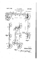
April 7, 1942. R. w. GRACE COVER FOR METER ENCLOSURES Filed May 31, 1938 2 Sheets-Sheet 1 N 'W W April 7, 1942. w, GRACE 2,279,165
COVER FOR METER ENCLOSURES v I Filed May 51,1938 2 Sheets-Sheet2 I 6- r 24 50 2 E 15 a I a 20 1 4 4f 5/ 16' is" I6 I] E F ii I.
Patented Apr. 7, 1942 COVER FOR METER ENCLOSURES a I Richard W. Grace, Canton, Ohio, assignor to The Superior Switchboard & Devices Company, Canton, Ohio, a. corporation of Ohio Application May 31, 1938, Serial No. 210,929
1 Claim.
The invention relates to covers for electric meter enclosures and more particularly to a cover adapted to accommodate a demand meter.
A common form of electric meter enclosure now in general use is provided with an opening in its front surface of suitable size and location to display the dials of the ordinary electric meter housed. therein, this opening being covered with glass to protect the meter and other devices enclosed within the box.
It frequently happens that it is desirable to places, demand meter within such an enclosure and the present invention concerns a cover for such demand meter which is adapted to be located over the usual opening above referred to, taking the place of the usual meter reading glass and arranged so that this cover may be opened to operate the manual demand reset attachment may be of the usual sheet metal construction provided with the removable front wall or cover II which may have therein a plurality of openings 12 corresponding to the number of meters to be enclosed.
of the meter without the necessity of opening the entire meter enclosure.
An object of the improvement is to provide I a cover for a demand meter so arranged and constructed that it may be installed in the place of the usual meter reading glass.
Another object is to provide a cover of this character which may be independently opened in order to operate the manual demand reset attachment of the meter.
A further object is to provide a novel and simple means for quickly and easily installing the demand reset cover.
A still further object is to provide means for holding the cover in open'position while operating the demand reset attachment.
Another object of the improvement is the provision of a novel spring device for holding either the meter reading glass or the demand reset cover in place.
The above objects together with others which will be apparent from the drawings or which may be later referred to may be attained by constructing the improved cover and associated parts in the manner illustrated in the accompanying drawings in which:
Figure 1 is a perspective view of a meter enclosure showing the invention applied thereto;
Fig. 2, a fragmentary elevation of the inside surface of the front wall or cover for the meter enclosure showing the improved demand reset cover installed in the place of the usual meter reading glass;
Fig. 3, a detached perspective view of one of the improved spring clips for attaching the meter reading glass or the demand reset cover;
Where the ordinary electric meter is housed, as indicated at It, a meter reading glass [4 is located over the corresponding opening 12, the dials of the meter i3 being displayed therethrough.
As shown in Fig. 7 the meter reading glass M may be held in place to cover the opening l2 by a simple and easily operated device including the channel shaped brackets I5 spotwelded or otherwise attached to the inner surface of the front wall or cover ll of the meter box,and located around and spaced from the four sides of the opening l2.
The innermost ear it of each of these channel brackets is provided with an aperture I! through which a spring locking clip indicated generally at 58 is adapted to be inserted.
Each of these spring clips has a U-shaped rear portion I9 adapted to be received between the ears of the channel bracket, the lower leg 20 of the U being considerably shorter than the upper leg 2! which is adapted to be inserted through the aperture I! in the inner ear it of the bracket and which is inclined downward so as to bear upon the glass It.
A transverse corrugation 22 is formed in the longer leg 2| of the clip and adapted to pass through the aperture ll when the clip is inserted and to form a stop to prevent accidental displacement of the clip.
It will be seen that the corrugation 22 will prevent movement of the clip in one direction while the end of the lower leg 20 substantially contacting with the ear l6 of the bracket prevents movement of the clip in the opposite direction.
In the meter enclosure shown in Figure 1 is illustrated a case in which three meters may be Fig. 4, a section taken as on the line -l4,
enclosed within the box, the meter I3 as above stated being the ordinary type of electric meter while two demand meters may be also located within the box the demand reset covers indicated generally at 23 and 24 being installed in the openings l2 in place of the usual meter reading glass.
The demand reset cover 24 differs from the cover 23 only that it is provided with a glass insert 25 to permit reading the meter without opening the cover 24. 23 and 24 may be identically the-samein construction and operation. For the above reason it is thought necessary to illustrate in detail only the cover 24.
A rectangular frame 26 is provided having an angular flange portion 21 of suitable dimensions to fit within the usual opening l2 of the front.
Otherwise the covers wall or cover II of the box. As the sheet metal from which this frame is formed is of considerably less thickness than the meter reading glass I4, which it replaces, it may be built up vtothe same thickness of the glass by spot-welding or otherwise connecting strips 28 of metal to its inner face.
The springz clips l8 may thenbe used to-detachably connect this frame within the opening l2 in the same manner as above described with reference to the meter reading glass. l 4.
The cover 24 has an angular flange 29 around its-edges adapted to fit over the angular flange 21 of. the frame 26 and hingedly connected to the upper endof said frame as at 3B.
For the purpose of holding the cover in open position, as shown in-E'ig. 5, when it is necessary to operate the demand reset attachment of the meter, afinger 3| pivoted as at 32 upon the flange of the cover may be swung down into the position shown-in Figs. 5 and 6 the free end thereof engaging over theflangeZ'l of the frame 26.
For the purpose of locking the cover 24 in closed position a hasp 33 may be connected to the lower portion of the flange 21 and adapted to extend througha suitable opening 34 in the front wall of the cover being provided with an aperture 35 arranged toregister with an aperture 36 in thehasp 31 carried by the front wall of the cover, whereby a lock or sealing wire may be located through the apertures 35 and 36.
T-hev glass panel 25 maybe mounted over the meter reading opening 38 in the front wall of the cover 24 and may be connected thereto as by putty or the like and in order to further assist in-preventingdisplacement of theglass panel a metal strip 39 may be spot welded or otherwise connected to each side flange 29 of the cover, the free ends thereof being bent over the edges of the glassas shown at 40.
From the above it will be seen that whenever it is necessary to operate the manual demand reset attachment of either one of the demand meters it is not necessary to open the entire front wall or cover of the meter box butonly necessary to raise the cover 23 or '24 of the particular demand meter which it is desired to reset.
It will also be seen that the improved demand reset cover may be quickly and easily installed in place of the usual meter reading glass of the ordinary meter enclosure or box.
In removing the meter reading glass and installing the demand reset cover in place thereof the screws 4| which attach the hinge 30 to the flange 21 of the frame 28, are removed so that the cover may be removed from the frame. The frame may then be inserted through the opening l2 from the inside of the cover or front wall ll of the meter box and the spring clips may then be inserted in place to hold the frame attached to the cover II.
The cover 23 or 24 as the case may be is then placed in position over the flange 21 and the hinge 30 attached to said flange by the screws 4|, the demand reset cover being then in position for use.
I claim:
A meter enclosure having a front wall provided.
with an opening, a closure member for the open- 7 clips located through said perforate ears and engaging over said closuremember, each spring.
clip being of U-shape with a short leg adapted to substantially contact the side of said perforated ear opposite said opening, and a long legextending through said perforated ear and in clamping.
engagement with said closure member and having, a transverse corrugation intermediate its ends anchoring said clip in said'ear.
RICHARD W. GRACE;
Priority Applications (1)
| Application Number | Priority Date | Filing Date | Title |
|---|---|---|---|
| US210929A US2279165A (en) | 1938-05-31 | 1938-05-31 | Cover for meter enclosures |
Applications Claiming Priority (1)
| Application Number | Priority Date | Filing Date | Title |
|---|---|---|---|
| US210929A US2279165A (en) | 1938-05-31 | 1938-05-31 | Cover for meter enclosures |
Publications (1)
| Publication Number | Publication Date |
|---|---|
| US2279165A true US2279165A (en) | 1942-04-07 |
Family
ID=22784901
Family Applications (1)
| Application Number | Title | Priority Date | Filing Date |
|---|---|---|---|
| US210929A Expired - Lifetime US2279165A (en) | 1938-05-31 | 1938-05-31 | Cover for meter enclosures |
Country Status (1)
| Country | Link |
|---|---|
| US (1) | US2279165A (en) |
Cited By (4)
| Publication number | Priority date | Publication date | Assignee | Title |
|---|---|---|---|---|
| US2441215A (en) * | 1945-09-28 | 1948-05-11 | Croname Inc | Mounting for glass scales |
| US3071218A (en) * | 1959-12-28 | 1963-01-01 | Mc Graw Edison Co | Evaporative cooler and pad frame latch means therefor |
| US20070175897A1 (en) * | 2006-01-24 | 2007-08-02 | Labcyte Inc. | Multimember closures whose members change relative position |
| FR2956742A1 (en) * | 2010-02-24 | 2011-08-26 | Sagem Comm | ELECTRICAL COUNTER EQUIPPED WITH A POSITIVE POSITIONABLE COVER IN TWO POSITIONS |
-
1938
- 1938-05-31 US US210929A patent/US2279165A/en not_active Expired - Lifetime
Cited By (8)
| Publication number | Priority date | Publication date | Assignee | Title |
|---|---|---|---|---|
| US2441215A (en) * | 1945-09-28 | 1948-05-11 | Croname Inc | Mounting for glass scales |
| US3071218A (en) * | 1959-12-28 | 1963-01-01 | Mc Graw Edison Co | Evaporative cooler and pad frame latch means therefor |
| US20070175897A1 (en) * | 2006-01-24 | 2007-08-02 | Labcyte Inc. | Multimember closures whose members change relative position |
| US8361418B2 (en) | 2006-01-24 | 2013-01-29 | Labcyte Inc. | Method for storing fluid with closure including members with changeable relative positions and device thereof |
| FR2956742A1 (en) * | 2010-02-24 | 2011-08-26 | Sagem Comm | ELECTRICAL COUNTER EQUIPPED WITH A POSITIVE POSITIONABLE COVER IN TWO POSITIONS |
| WO2011103991A1 (en) * | 2010-02-24 | 2011-09-01 | Sagemcom Energy & Telecom Sas | Electric meter equipped with a removable cover that can be positioned in two positions |
| CN102906576A (en) * | 2010-02-24 | 2013-01-30 | 萨基姆通讯能源及电信联合股份公司 | Electric meter equipped with a removable cover that can be positioned in two positions |
| US8823363B2 (en) | 2010-02-24 | 2014-09-02 | Sagemcom Energy & Telecom Sas | Electric meter equipped with a removable cover that can be positioned in two positions |
Similar Documents
| Publication | Publication Date | Title |
|---|---|---|
| US2757818A (en) | Panel and box construction | |
| US2330975A (en) | Enclosure for electrical devices | |
| US2279165A (en) | Cover for meter enclosures | |
| US2106003A (en) | Terminal box | |
| GB1136244A (en) | Improvements relating to information display equipment | |
| US3202881A (en) | Electrical panelboard enclosure | |
| US1200477A (en) | Hinge. | |
| US4383519A (en) | Door frame and handle combination | |
| US3956977A (en) | Fume hood with removable enclosure panels | |
| US1486415A (en) | Meter box | |
| US1662275A (en) | Switch box | |
| US2822417A (en) | Cover with slidable insert for socket meter enclosures | |
| US1716038A (en) | Access door | |
| US2680533A (en) | Enclosure mounting device | |
| US2295304A (en) | Cabinet structure | |
| US2324738A (en) | Hinged cover for electrical apparatus | |
| US2426712A (en) | Instrument housing comprising inner and outer housings and a flexible closure therebetween | |
| US3027211A (en) | Dispenser frame and housing construction | |
| US3087097A (en) | Auxiliary cover for meter socket | |
| US2200304A (en) | Heater | |
| US2587527A (en) | Oven door construction | |
| US2662109A (en) | Sectional housing for electrical control and ignition apparatus of fluid fuel burners | |
| US2651008A (en) | Meter box and cover | |
| US3418420A (en) | Junction box extension device | |
| US2782455A (en) | Hinge construction for cable terminal |