US2125308A - Means for and method of applying a patch to a satchel bottom bag - Google Patents
Means for and method of applying a patch to a satchel bottom bag Download PDFInfo
- Publication number
- US2125308A US2125308A US738095A US73809534A US2125308A US 2125308 A US2125308 A US 2125308A US 738095 A US738095 A US 738095A US 73809534 A US73809534 A US 73809534A US 2125308 A US2125308 A US 2125308A
- Authority
- US
- United States
- Prior art keywords
- patch
- blank
- flaps
- bag
- folding
- Prior art date
- Legal status (The legal status is an assumption and is not a legal conclusion. Google has not performed a legal analysis and makes no representation as to the accuracy of the status listed.)
- Expired - Lifetime
Links
Images


Classifications
-
- B—PERFORMING OPERATIONS; TRANSPORTING
- B31—MAKING ARTICLES OF PAPER, CARDBOARD OR MATERIAL WORKED IN A MANNER ANALOGOUS TO PAPER; WORKING PAPER, CARDBOARD OR MATERIAL WORKED IN A MANNER ANALOGOUS TO PAPER
- B31B—MAKING CONTAINERS OF PAPER, CARDBOARD OR MATERIAL WORKED IN A MANNER ANALOGOUS TO PAPER
- B31B70/00—Making flexible containers, e.g. envelopes or bags
- B31B70/60—Uniting opposed surfaces or edges; Taping
- B31B70/62—Uniting opposed surfaces or edges; Taping by adhesives
-
- B—PERFORMING OPERATIONS; TRANSPORTING
- B31—MAKING ARTICLES OF PAPER, CARDBOARD OR MATERIAL WORKED IN A MANNER ANALOGOUS TO PAPER; WORKING PAPER, CARDBOARD OR MATERIAL WORKED IN A MANNER ANALOGOUS TO PAPER
- B31B—MAKING CONTAINERS OF PAPER, CARDBOARD OR MATERIAL WORKED IN A MANNER ANALOGOUS TO PAPER
- B31B2150/00—Flexible containers made from sheets or blanks, e.g. from flattened tubes
- B31B2150/001—Flexible containers made from sheets or blanks, e.g. from flattened tubes with square or cross bottom
- B31B2150/0012—Flexible containers made from sheets or blanks, e.g. from flattened tubes with square or cross bottom having their openings facing in the direction of movement
-
- B—PERFORMING OPERATIONS; TRANSPORTING
- B31—MAKING ARTICLES OF PAPER, CARDBOARD OR MATERIAL WORKED IN A MANNER ANALOGOUS TO PAPER; WORKING PAPER, CARDBOARD OR MATERIAL WORKED IN A MANNER ANALOGOUS TO PAPER
- B31B—MAKING CONTAINERS OF PAPER, CARDBOARD OR MATERIAL WORKED IN A MANNER ANALOGOUS TO PAPER
- B31B2150/00—Flexible containers made from sheets or blanks, e.g. from flattened tubes
- B31B2150/003—Flexible containers made from sheets or blanks, e.g. from flattened tubes made from tubular sheets
-
- B—PERFORMING OPERATIONS; TRANSPORTING
- B31—MAKING ARTICLES OF PAPER, CARDBOARD OR MATERIAL WORKED IN A MANNER ANALOGOUS TO PAPER; WORKING PAPER, CARDBOARD OR MATERIAL WORKED IN A MANNER ANALOGOUS TO PAPER
- B31B—MAKING CONTAINERS OF PAPER, CARDBOARD OR MATERIAL WORKED IN A MANNER ANALOGOUS TO PAPER
- B31B2160/00—Shape of flexible containers
- B31B2160/10—Shape of flexible containers rectangular and flat, i.e. without structural provision for thickness of contents
- B31B2160/106—Shape of flexible containers rectangular and flat, i.e. without structural provision for thickness of contents obtained from sheets cut from larger sheets or webs before finishing the bag forming operations
-
- B—PERFORMING OPERATIONS; TRANSPORTING
- B31—MAKING ARTICLES OF PAPER, CARDBOARD OR MATERIAL WORKED IN A MANNER ANALOGOUS TO PAPER; WORKING PAPER, CARDBOARD OR MATERIAL WORKED IN A MANNER ANALOGOUS TO PAPER
- B31B—MAKING CONTAINERS OF PAPER, CARDBOARD OR MATERIAL WORKED IN A MANNER ANALOGOUS TO PAPER
- B31B2160/00—Shape of flexible containers
- B31B2160/20—Shape of flexible containers with structural provision for thickness of contents
Definitions
- One feature of the invention consists in the provision of means for and methods of opening out a flap of such a bag.
- Another" feature consists in the provision of means for and methods of applying a patch to said flaps and of so folding the flaps that the folding line will pass transversely through the patch.
- a further feature consists in the provision of means for and methods of adhering each flap to the other flap and to the patch, and of adhering ends of the patch to other portions thereof.
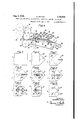
- Fig. 1 is a fragmentary plan view illustrating mechanisms for folding a web into tubular form.
- Fig. 2 is a fragmentary plan view illustrating a portion of flap-forming mechanisms, the showing at the left-hand extremity of this figure slightly overlapping the showing at the right-hand -extremity of Fig. 1.
- Fig. 3 is a fragmentary side elevational view illustrating tube-cutting and blank-feeding mech anisms, and flap-gumming, patch-applying and flap -folding mechanisms, the showing at the lefthand portion of this figure corresponding with the showing of Fig. 2.
- Fig. 4 is a fragmentary side elevational view illustrating bag-conveying and flap-folding mechanisms, the showing at the left-hand extremity of this figure slightly overlapping the, showing at the right-hand extremity of Fig. 3.
- Fig. 5 is a fragmentary plan view of one end of a tube from which a bag is to be formed.
- Fig. 6 is a fragmentary plan view similar to Fig. 5, but with the bag corners tucked in and folded down.
- Fig. '7 is a plan view similar to Fig. 6, but with the upper flap of the bag bottom folded back upon the bag body.
- Fig. 8 is a plan view similar to Fig. '7, but with areas of gum applied to the flaps.
- Fig. 9 is a plan view similar to Fig. 8, but with a patch applied to the gummed areas of the flaps.
- Fig. 10 is a plan view similar to Fig. 9, but with the rear flap scored to provide a folding line.
- Fig. 11 is a plan view similar to Fig. 10, but with areas of gum applied to the flaps and to the patch.
- Fig. 12 is a plan view similar to Fig. 11, but with the forward flap folded down upon one of the gummed areas and into adhesive contact with the patch and the bag bottom.
- Fig. 13 is a plan view illustrating the completed bag bottom,'the rear flap having been folded down upon and adhered to the forward flap and the patch.
- a work web I (Fig. 1), which may be of Cellophane, paper, or any other suitable bag material, is supplied from a reel (not shown).
- the web is drawn forward intermittently by a feeder 2 (Figs. 1, 2 and 3). It is preferable not to require the feeder 2 to draw the web directly from the reel, since such operation would necessitate that the inertiaof the reel be overcome at the beginning of each feeding operation.
- the inertia of the reel acting in direct opposition to the feeder 2 it would be apt to cause slipping of the web relative to the feeder, with a consequent production of bags which would be defective because of being of less than desired length.
- Feeder 2 draws the web between guides 3 and folding plates 4 to form it into a tube 5 (Figs. 1 and 5), mechanisms (not shown) being provided for gumming one margin of the tube and adhering it to the opposite margin.
- the leading end of the tube is acted upon by two oscillating tucker blades 6 .(Fig. 2), which co-operate with a bifurcated plate I (Fig. 3) to inwardly tuck oppositely-disposed sides of the tube, as shown in Fig. 6, in order to form an upper tab 5a and a lower tab 5b.
- the feeder 2 acts to advance the web the length of one blank.
- the leading end of tube 5 is carried between a suction roller 8 (Figs. 2 and 3) and a roller 9, co-operative therewith.
- the suction roller is so constructed and arranged that it operates to raise the upper tab 511 of the leading end of the tube, while leaving the lower tab 5b free to continue along the normal path of blank movement.
- the leading end of the tube passes next through a pair of rollers to (Fig. 2), which rollers complete the folding back upon the body (Fig. '1) of the tube of the upper tab 5a which has been raised by suction roller 8.
- This web is drawn from the reel by continuously-operating feed ro1lers'35 and 35 and over idler roller 31.
- the patch material is fed onto atable 38, the forward edge of which is providedwith a shearing block 39, forming one element of a patch-severing device.
- a blade 40 is adapted to coact with the block 39, being carried by a rocking frame 4! which is normally held up by a spring 42, connected to an ear 43 of the rocking frame and to a fixed frame member (not shown).
- the rocking frame is provided with a roller 44 which serves as a cam follower for engaging the cause a patch to be severed.
- the roller 35 is journalled in afurther rockingframe '41, car'- ried by a rock-shaft 48.
- One member of the rocking frame 41 is provided with a tail portion 49, which engages a disk 50.
- This disk 50 is rotatably mounted upon a shaft 5
- the disk 50 may be turned by means of a handle 53 to raise the tail portion 43, in order to lift feed roller 35 out of engagement with feed roller 35, thereby facilitating the threading of a new web between the feed rollers.
- a spring 54 connected to an arm 55 of the rocking frame 4'! and to a fixed part of the machine frame, acts to urge the rocking frame 41 clockwise and hence to urge feed roller 35 toward feed roller 35.
- the leading end of the web 34 which protrudes beyond the cutting block 39 extends into the path of a patch transferring and applying segment 55, which travels about a hollow shaft 51 and co-operates with a bed cylinder 58.
- the segment 55 travels into supporting relation to the web end, lifting it to a position where the patch web 34 is sucked against it while it is slack.
- segment 55 then travels further in a counter- K of the hollow shaft 51.
- -'Segment 55 is carried by a rocker arm 59, which is mounted upon a stud 50, on a crank 5
- the tendency of the spring 52 is to project the segment 55 outward, i. e., away from the axis of the hollow shaft 51.
- the outward limit of movement of the segment is controlled by an adjusting screw 55, which is threaded through the tail portion 52 and which engages a hub 55 of the'crank 5!.
- a look nut 51 is provided for maintaining the screw 55 in adjusted position.
- the suction is applied through ducts (not shown), formed in the segment 55 and in the rockerv arm 59. These ducts communicate through a nipple with a flexible tube 68.
- the tube in turn communicates through a nipple with a radial passage (not shown), formed in the wall of the hollow shaft 51.
- the radial passage communicates through axial passage 69 of the hollow shaft 51 with a suitable source of suction (not shown).
- the flexible tube 58 turns with the hollow shaft 51, and is adapted toyield to accommodate such movements of the segment 55 relative to the hollow shaft 51 as occur in the the screw 55.
- the blank After the patch 55a is applied to a blank, the blank presents the appearance indicated in Fig. 9. It is then delivered by conveyor l5 to scoring rolls 10 and H, which score the trailing tab of the blank in the manner indicated at I la in Fig. 10. Upon passing between the said scoring rollers, the blank enters the bight of rollers 12 and 13. Segments of roller 12 are charged with gum by'a contacting gum pick-up roller 14 (Fig. 4), which rotates in a body of gum contained in a gum pot 15. These gum segments apply two patches, 15a and 15b, of gum to the patch 29a. and to the tabs 5a and 5b, as indicated in Fig. l
- Roller 12 is .also provided with a tucker blade 15, co-operative with a clamping blade (not shown), which is carried by a rock-shaft 11,
- Conveyor belts I5 run over end rollers 85 and 88, over belt-tightening rollers 81, 88 and 89, and over roller tables 99 of arcuate form.
- the blank is thus caused to travel in a curved path and is held in a curved position.
- the convexity of the conveyor causes the gummed portion of the unfolded tab to stand out tangent to the conveyor, and away from the body of the blank, so that the insertion is facilitated of a folding device 99.
- is swung down to lie momentarily in close proximity to the traveling blank.
- is secured to a rock-shaft 92, which shaft is connected through a crank 93 to a thrust rod 94, in turn connected to actuating means (not shown).
- Folding device 99 is operated along the path of the conveyor belts I8 and 89, to co-operate with the tucker blade 9
- the folding device comprises a folding plate 95 which is fixed upon an arm 98, secured to a rock-shaft 91.
- the rock-shaft is pivoted upon two oscillating arms 98, one being at each end thereof.
- a spring 99 is connected between one of the arms 98 and an arm 96a at one side of shaft 91, and pulls downward upon said arm.
- the arm 96a carries a roller I99 at the outer end thereof, which roller rides upon a cam plate IIII, located adjacent the conveyor belts.
- the roller I 99 is gradually raised in its approach to a protuberance I98 01' the cam plate IIlI, causing the plate 95 to lift the rear end of the unfolded tab and fold it'around the edge of tucker blade 9I.'
- the blade 9I desirably withdraws after the tab is partly folded to prevent the gummed portion I5 of the tab coming into contact with it.
- the roller I99 then descends into a depression I98 of cam plate I M, which causes the plate 95 to rock forward and downward as it advances, to complete the folding of the tab. At this time the plate 95 travels at about the same speed as that of the bag.
- Means for actuating and controlling the webfeeding and tube-forming apparatus of Fig. 1, the flap-tucking apparatus of Figs. 2 and 3, the blank-cutting and blank-feeding apparatus of Fig. 3, the gumming and tucking elements I2 and I3 of Figs. 3 and 4, and the flap-folding and bagconveying apparatus of Fig. 4, are illustrated, described, and claimed in my pending application, Serial No. 734,978 filed July 13, 1934.
- means for forming a tubular bag blank means for folding the bottom flaps of said bag blank, means foroppositely disposing the points of said flaps, means for continuously advancing the blank, means for applying a patch to said flaps while the blank is in motion, means for folding the flaps across'said patch, and means for adhering said flaps to said patch.
- means for forming a tubular bag blank means for folding and flattening the flaps of said bag blank, means for continuously advancing the blank, means for applying a patch bridging the gap between said flaps while the blank is in motion, means forfolding the ends of the flaps across the patch, and means for adhering said flap folds to the patch and to each other.
- apparatus of the character -descrlbed means for forming a tubular bag' blank, means for folding and flattening the flaps of said bag blank, means for continuously advancing the blank, means for applying a patch spanning the'gap between said flaps while the blank is in motion, mean for folding the flaps across the patch, means' or adhering one flap to the patch and to the bag bottom, and means for adhering the other flap to the patch, to said first flap, and to the bag bottom.
- means for forming a tubular bag blank means coordinated with said foregoing means, for supplying a patch, means for applying said patch to the bottom flaps of the bag blank while the blank is in motion, means for effecting folds across the flaps and transversely across said patch, and means for adhering said flaps to said patch and to each other.
- a bag-making machine the combination of means for feeding a web, means for forming a tube from said web, means for inwardly tucking oppositely-disposed sides of said tube to form parallel flaps, means for severing the thereby-formed blank from the tube, means for raising one of said flaps from the other flap and for pressing it back upon the body of the blank, means for applying adhesive to said flaps, means.
- a patched satchel-bottom bag which consists in forming a tube from a web, forming flaps in the sides of a tubular blank, continuously advancing the blank, and adhering a patch to said flaps, folding said flaps across said patch, and adhering said flaps to said patch and to each other and the ends of said patch to the portion thereof between the folding lines of the flaps and patch, all while the blank is in motion.
- the method of making a bag which consists in forming a tube from a web, forming triangular fiaps in the sides of the tube, severing the blankfrom the tube, adhering a patch to the flaps, adhering a triangular portion of each flapto the patch and to the other flap, and adhering end portions of the patch to other nortions thereof.
- the method of sealing a bag bottom which consistsin forming flaps in a tube, superposing one flap upon the body-of the tube, adhering a patch to the flaps, gumming portions of the flaps and of the patch, folding one flap to adhesively superpose a portion thereof upon the patch and a portion of the patch upon another portion thereof, and folding the other flap to adhesively superpose a portion thereof upon the first flap and upon the patch and'a portion of the patch upon another portion thereof.
Landscapes
- Making Paper Articles (AREA)
Description
A. NOVICK 2,125,308
MEANS FOR AND METHOD OF APPLYING A PATCH TO A SATCHELBOTTOM BAG I Aug. 2, 1938.
Original Filed Aug. 2, 1954 5 Sheets-Sheet l 7 1 W\ a W. l x a w 4/5. m H m M 1| J n. ww m T0 E NN N m m N m Z m. .P
Aug, 2, 1938. A. NOVICK MEANS FOR AND METHOD .OF' APPLYING A PATCH TO A SATCHELBOTTOM'BAG s Shets-Sheet 2 Original Filed Aug. 2, 1934 INVENTOR. Abra/7am Nor/ck.
A TTORNEYS.
Au 2, 1938. A WC 2,125,308
MEANS FOR AND METHOD OF APPLYING A PATCH TO A SATCHEL BOTTOM BAG Original Filed Aug. 2, 1934 3 Sheets-Sheet 3 INVEN TOR. Abraham Nov/ck.
BY QWM Q;
A TTORNEYS.
Patented Aug. 2, 1938 MEANS FOR AND METHOD or APPLYING A ra'rcn To A SATCHEL BOTTOM BAG Abraham Novick, Flushing, N. Y., assignor to F. L. Smithe Machine Co. Inc., New York, N. Y., a corporation of New York Application August 2, 1934, Serial No. 738,095 Renewed April 14, 1938 16 Claims. (Cl. 93-27) This invention relates to means for and methods of applying a patch to a satchel-bottom bag.
One feature of the invention consists in the provision of means for and methods of opening out a flap of such a bag.
Another" feature consists in the provision of means for and methods of applying a patch to said flaps and of so folding the flaps that the folding line will pass transversely through the patch.
A further feature consists in the provision of means for and methods of adhering each flap to the other flap and to the patch, and of adhering ends of the patch to other portions thereof.
Other features and advantages of the invention will hereinafter appear.
The bags contemplated to be made in accordance with the present invention are such as are illustrated and described in my pending application, Serial No. 715,604, filed March 15, 1934.
The invention will best be understood by reference to the accompanying drawings wherein is shown the present preferred embodiment thereof. and wherein Fig. 1 is a fragmentary plan view illustrating mechanisms for folding a web into tubular form.
Fig. 2 is a fragmentary plan view illustrating a portion of flap-forming mechanisms, the showing at the left-hand extremity of this figure slightly overlapping the showing at the right-hand -extremity of Fig. 1.
Fig. 3 is a fragmentary side elevational view illustrating tube-cutting and blank-feeding mech anisms, and flap-gumming, patch-applying and flap -folding mechanisms, the showing at the lefthand portion of this figure corresponding with the showing of Fig. 2.
Fig. 4 is a fragmentary side elevational view illustrating bag-conveying and flap-folding mechanisms, the showing at the left-hand extremity of this figure slightly overlapping the, showing at the right-hand extremity of Fig. 3.
Fig. 5 is a fragmentary plan view of one end of a tube from which a bag is to be formed.
Fig. 6 is a fragmentary plan view similar to Fig. 5, but with the bag corners tucked in and folded down.
Fig. '7 is a plan view similar to Fig. 6, but with the upper flap of the bag bottom folded back upon the bag body.
Fig. 8 is a plan view similar to Fig. '7, but with areas of gum applied to the flaps.
Fig. 9 is a plan view similar to Fig. 8, but with a patch applied to the gummed areas of the flaps.
Fig. 10 is a plan view similar to Fig. 9, but with the rear flap scored to provide a folding line.
Fig. 11 is a plan view similar to Fig. 10, but with areas of gum applied to the flaps and to the patch.
Fig. 12 is a plan view similar to Fig. 11, but with the forward flap folded down upon one of the gummed areas and into adhesive contact with the patch and the bag bottom.
Fig. 13 is a plan view illustrating the completed bag bottom,'the rear flap having been folded down upon and adhered to the forward flap and the patch. v
Like reference characters indicate like parts throughout the drawings.
Referring to the drawings: A work web I (Fig. 1), which may be of Cellophane, paper, or any other suitable bag material, is supplied from a reel (not shown). The web is drawn forward intermittently by a feeder 2 (Figs. 1, 2 and 3). It is preferable not to require the feeder 2 to draw the web directly from the reel, since such operation would necessitate that the inertiaof the reel be overcome at the beginning of each feeding operation. The inertia of the reel acting in direct opposition to the feeder 2, it would be apt to cause slipping of the web relative to the feeder, with a consequent production of bags which would be defective because of being of less than desired length.
Provision may accordingly be made of mechanism, hereinafter referred to, for producing slack in the web.
Feeder 2 draws the web between guides 3 and folding plates 4 to form it into a tube 5 (Figs. 1 and 5), mechanisms (not shown) being provided for gumming one margin of the tube and adhering it to the opposite margin. After passing through feeder 2, the leading end of the tube is acted upon by two oscillating tucker blades 6 .(Fig. 2), which co-operate with a bifurcated plate I (Fig. 3) to inwardly tuck oppositely-disposed sides of the tube, as shown in Fig. 6, in order to form an upper tab 5a and a lower tab 5b. As soon as the tucker blades are withdrawn from the path of web movement, the feeder 2 acts to advance the web the length of one blank.
Under the urge of feeder 2, the leading end of tube 5 is carried between a suction roller 8 (Figs. 2 and 3) and a roller 9, co-operative therewith. The suction roller is so constructed and arranged that it operates to raise the upper tab 511 of the leading end of the tube, while leaving the lower tab 5b free to continue along the normal path of blank movement. The leading end of the tube passes next through a pair of rollers to (Fig. 2), which rollers complete the folding back upon the body (Fig. '1) of the tube of the upper tab 5a which has been raised by suction roller 8. The
tube then again comes to rest, and the blank is Referring now to Fig. 3: The severed blank,
with ItsJeading end in the form shown in Fig. 7, now passes from rollers l4 into 'the bight of a conveyor l5, comprising two lower belts, i5 and two co-operative hold-down belts I! also shown in Fig. 2). Lower belts l5 run vover rollers l8, I9,
20, 2| and 22, the supporting shafts of which rollers are mounted in arcuate position, in order that the belts may better grip the blank. These lower belts also run over belt-tightening rollers 23 and 24. Hold-down belts l1 runover end rollers 25 and 25, and are provided with belt-tightening rollers 21 and 28. In the course of its movement by the conveyor IS, the folded forwardportion of the blank passes between bed cylinder [9a and a gum-applying segment '29, disposed between the two hold-down belts IT. This segment is periodically charged with adhesive from a gumtransfer roller 30, in peripheral contact with a gum pick-up roller 3|, rotating in a body of gum in a gum pot 32. The form of this gum deposit 29a is shown in Fig. 8.
Carried by a. reel 33 is a. patch web 314. This web is drawn from the reel by continuously-operating feed ro1lers'35 and 35 and over idler roller 31. The patch material is fed onto atable 38, the forward edge of which is providedwith a shearing block 39, forming one element of a patch-severing device. A blade 40 is adapted to coact with the block 39, being carried by a rocking frame 4! which is normally held up by a spring 42, connected to an ear 43 of the rocking frame and to a fixed frame member (not shown).
The rocking frame is provided with a roller 44 which serves as a cam follower for engaging the cause a patch to be severed. The roller 35 is journalled in afurther rockingframe '41, car'- ried by a rock-shaft 48.- One member of the rocking frame 41 is provided with a tail portion 49, which engages a disk 50. .This disk 50 is rotatably mounted upon a shaft 5|, and has a fiat 52 closeto whigh the tail portion 49 normally lies, thus permitting feed roller 35 normally to coact with feed roller 35. The disk 50 may be turned by means of a handle 53 to raise the tail portion 43, in order to lift feed roller 35 out of engagement with feed roller 35, thereby facilitating the threading of a new web between the feed rollers. A spring 54, connected to an arm 55 of the rocking frame 4'! and to a fixed part of the machine frame, acts to urge the rocking frame 41 clockwise and hence to urge feed roller 35 toward feed roller 35.
The leading end of the web 34 which protrudes beyond the cutting block 39 extends into the path of a patch transferring and applying segment 55, which travels about a hollow shaft 51 and co-operates with a bed cylinder 58. The segment 55 travels into supporting relation to the web end, lifting it to a position where the patch web 34 is sucked against it while it is slack. The
. segment 55 then travels further in a counter- K of the hollow shaft 51.
clockwise direction, dragging the web over its surface and into a positionwhere the web is' taut,
in which position the patch is severed from the web. fI'he leading end of the web and the patch severed therefrom are retained in position on the segment in a manner now to be described.
-'Segment 55 is carried by a rocker arm 59, which is mounted upon a stud 50, on a crank 5| A tail portion 62 of the rocker arm 59 is drawn toward the axis of the 1 hollow shaft 5] by a spring 53, connected to said 7 tail portion 62 and to a pin 54, which travels with the shaft.
The tendency of the spring 52 is to project the segment 55 outward, i. e., away from the axis of the hollow shaft 51. The outward limit of movement of the segment is controlled by an adjusting screw 55, which is threaded through the tail portion 52 and which engages a hub 55 of the'crank 5!. A look nut 51 is provided for maintaining the screw 55 in adjusted position. With this arrangement the segment 55 is adapted to yield when it engages the bag blank, and hence to apply the patch with light but firm and substantially uniform pressure to the blank. The arrangement disclosed does not ordinarily require resetting for operating upon blanks of different thicknesses, nor is it affected by any reasonable amount of wear.
The suction is applied through ducts (not shown), formed in the segment 55 and in the rockerv arm 59. These ducts communicate through a nipple with a flexible tube 68. The tube in turn communicates through a nipple with a radial passage (not shown), formed in the wall of the hollow shaft 51. 'The radial passage communicates through axial passage 69 of the hollow shaft 51 with a suitable source of suction (not shown). The flexible tube 58 turns with the hollow shaft 51, and is adapted toyield to accommodate such movements of the segment 55 relative to the hollow shaft 51 as occur in the the screw 55.
After the patch 55a is applied to a blank, the blank presents the appearance indicated in Fig. 9. It is then delivered by conveyor l5 to scoring rolls 10 and H, which score the trailing tab of the blank in the manner indicated at I la in Fig. 10. Upon passing between the said scoring rollers, the blank enters the bight of rollers 12 and 13. Segments of roller 12 are charged with gum by'a contacting gum pick-up roller 14 (Fig. 4), which rotates in a body of gum contained in a gum pot 15. These gum segments apply two patches, 15a and 15b, of gum to the patch 29a. and to the tabs 5a and 5b, as indicated in Fig. l
mounted in the roller 13. These blades engage the leading tab 517 of the blank along a desired folding line thereof, and the blank is carried by said roller 13 into engagement with conveyor belts 18 (Fig. 4), which coact with said roller to fold the tab Shinto contact with the adjacent gummed area 15b on the patch and the bag body. The tab is thus caused to adhere in the position indicated in'Fig. 12. Strippers I9 deflect the blank away from roller 13 and guide it into the bight of hold-down conveyor belts l8 and conveyor belts 80. Hold-down conveyor belts I8 marginally engage the blank; and these belts run over end rollers 8i and 82 and over belttightening rollers 83 and 84. Conveyor belts I5 run over end rollers 85 and 88, over belt- tightening rollers 81, 88 and 89, and over roller tables 99 of arcuate form. The blank is thus caused to travel in a curved path and is held in a curved position. The convexity of the conveyor causes the gummed portion of the unfolded tab to stand out tangent to the conveyor, and away from the body of the blank, so that the insertion is facilitated of a folding device 99.
After the blank is advanced a sufficient distance along the conveyor belts I8 and 89, a tucker blade 9| is swung down to lie momentarily in close proximity to the traveling blank. This tucker blade 9| is secured to a rock-shaft 92, which shaft is connected through a crank 93 to a thrust rod 94, in turn connected to actuating means (not shown).
standing unfolded trailing tab to reach a position definitely in advance of the plate 95. The arms 98 then sweep forward at a speed considerably greater than that at which the blank is being moved by the conveyor. When the leading edge of the plate 95 is a short distance behind the trailing end of the unfolded tab, the roller I99 drops into a depression I92 of the cam plate I8I, causing the plate 95 to descend into a position almost in contact with the blank and with its forward edge substantially tangent to the conveyor. The arms 98 continue their rapid advance, inserting the plate 95 beneath the unfolded tab 5a. During this movement, the roller I 99 is gradually raised in its approach to a protuberance I98 01' the cam plate IIlI, causing the plate 95 to lift the rear end of the unfolded tab and fold it'around the edge of tucker blade 9I.' The blade 9I, however, desirably withdraws after the tab is partly folded to prevent the gummed portion I5 of the tab coming into contact with it. The roller I99 then descends into a depression I98 of cam plate I M, which causes the plate 95 to rock forward and downward as it advances, to complete the folding of the tab. At this time the plate 95 travels at about the same speed as that of the bag. This depression I84 is so deep that the full force of spring 99 is borne by the bag, so that a sharply-defined crease is produced in the tab. The arm 98 is then again" swung rapidly forward to draw the plate 95 over the folded tab and iron it. The roller, Ill
reaches a further depression I95 of cam plate IIlI before the forward edge of the newly-folded tab has come opposite the depression; and the roller is again permitted to descend to apply the full force of spring 99, through the plate 95, to the bag. The plate 95 is now caused to remain stationary in this position while the newly-folded tab of the blank is advanced beyond the depression I95. The bag, in its finished form as illustrated in Fig. 13, is then fed out by the conveyor belts I8 and 89, and the arms 98 are returned to restore the plate 95 to its original position, as illustrated in Fig. 4.
Means for actuating and controlling the webfeeding and tube-forming apparatus of Fig. 1, the flap-tucking apparatus of Figs. 2 and 3, the blank-cutting and blank-feeding apparatus of Fig. 3, the gumming and tucking elements I2 and I3 of Figs. 3 and 4, and the flap-folding and bagconveying apparatus of Fig. 4, are illustrated, described, and claimed in my pending application, Serial No. 734,978 filed July 13, 1934.
Means for actuating and controlling the blankconveying, fiap-gumming, and patch-applying apparatus of Fig. 4, are illustrated, described, and claimed in my pending application, Serial No. 734,977, filed July 13, 1934.
It is to be understood that the embodiment of the invention herein shown and described is merely illustrative, and that, without departing from its principle, it may be embodied in other forms and structures.
I claim: v
1. In a unitary apparatus of the character described, means for forming a tubular bag blank, means for folding the bottom flaps of said bag blank, means foroppositely disposing the points of said flaps, means for continuously advancing the blank, means for applying a patch to said flaps while the blank is in motion, means for folding the flaps across'said patch, and means for adhering said flaps to said patch.
2. In a unitary apparatus of the character described, means for forming a tubular bag blank, means for folding and flattening the flaps of said bag blank, means for continuously advancing the blank, means for applying a patch bridging the gap between said flaps while the blank is in motion, means forfolding the ends of the flaps across the patch, and means for adhering said flap folds to the patch and to each other.
3. In a unitary. apparatus of the character -descrlbed means for forming a tubular bag' blank, means for folding and flattening the flaps of said bag blank, means for continuously advancing the blank, means for applying a patch spanning the'gap between said flaps while the blank is in motion, mean for folding the flaps across the patch, means' or adhering one flap to the patch and to the bag bottom, and means for adhering the other flap to the patch, to said first flap, and to the bag bottom.
4.111 a. unitary apparatus of the character described,'means for forming a tubular bag blank,'means for continuously advancing said blank, means coordinated with said foregoing means for supplying a patch, means for applying said patch to the bottom flaps of the bag blank, while the blank is in motion, means for eflecting folds through said patch and said flaps,
and means for adhering said flaps to said patch. 5. In a unitary apparatus of the character described, means for forming a tubular bag blank, means coordinated with said foregoing means, for supplying a patch, means for applying said patch to the bottom flaps of the bag blank while the blank is in motion, means for effecting folds across the flaps and transversely across said patch, and means for adhering said flaps to said patch and to each other.
6.In apparatus of the character described,
means for forming flaps in a bag blank bottom, means for raising and flattening one of said flaps,
and means for continuously advancing the blank, and flap-gumming, patch-applying and flap-folding devices, all acting on the traveling blank while the same is in motion.
7. In a bag-making machine, the combination of means for feeding a web, means for forming a tube from said web, means for inwardly tucking oppositely-disposed sides of said tube to form parallel flaps, means for severing the thereby-formed blank from the tube, means for raising one of said flaps from the other flap and for pressing it back upon the body of the blank, means for applying adhesive to said flaps, means.
for feeding a web of patch material, means for cutting a patch from said web, means for applyingsaid patch to the gummed areas of said flaps, means for scoring a folding line across one of said flaps and said patch, means for applying adhesive to said flaps and said patch, .means for folding the unscored flap across said patch and into adhesive contact with said patch, means for folding the other flap along said scored line and into adhesive contact with the folded flap and the patch, and means for pressing said flaps and for delivering the thereby-formed bag.
8. The method of applying a patch to a satchel-bottom bag which consists in forming two triangular flaps in the sides of a tube, folding one of said flaps back upon the body of the tube, severing a. bag blank from the tube, continuously advancing the blank, adhering a patch to said flaps, while the blank is in motion to cover a portion of the gap between said flaps, folding the flaps and the patch, and adhering the flaps to the patch and to each other.
9. The method of applying patches to satchelbottom bags which consists in forming two flaps parallel to the sides of the tag blank, folding one of said flaps back upon the blank, continuously advancing the blank, and gumming areas. of said flaps, applying a patch to said gummed areas, folding said flaps across said patch, and pressing them ,into adhesive contact with said patch and with each other, all .while the blank is in motion.
10. The method of making a patched satchelbottom bag which consists forming a tube from a web, inwardly tucking oppositely disposed portions of the tube to form parallel flaps, severing the blank from the tube, raising one of the flaps and foiding it back upon the blank, gumming the flaps, applying a patch to the gumrned areas of the flaps, gumming said flaps and said patch, folding said flaps across the patch, and pressing said flaps and patch into adhesive con= tact with each other.
11. The continuous method of making a patched satchel-bottom bag which consists in forming a tube from a web, forming flaps in the sides of a tubular blank, continuously advancing the blank, and adhering a patch to said flaps, folding said flaps across said patch, and adhering said flaps to said patch and to each other and the ends of said patch to the portion thereof between the folding lines of the flaps and patch, all while the blank is in motion.
12. The continuous method of sealing the bottom of a. bag which consists in forming a tubular bag blank, and in forming in said bag blank twoflaps one of which extends beyond the body of the blank and the other of which is folded back upon said body, continuously advancing the blank, adhering a patch to adjacent portions of said fiaps while the blank is in motion, gumming portions of said flaps and patch, and so folding said flaps and patch that each flap is adhered to its ownflap area, to the other flap, and to the patch, and the ends of the patch outside the fold lines are adhered to the portion of the patch within the fold lines.
13. The method of sealing the bottom of a bag blank which consists in continuously advancing the blank, forming a patch in proximity to the blank, adhering said patch to the blank bottom while the blank is in motion, and adhering portions of the bag to the patch and portions of the patch to other portions of the patch.
14. The method of making a bag which consists in forming a tube from a web, forming triangular fiaps in the sides of the tube, severing the blankfrom the tube, adhering a patch to the flaps, adhering a triangular portion of each flapto the patch and to the other flap, and adhering end portions of the patch to other nortions thereof.
15. The method of sealing a bag bottom which consistsin forming flaps in a tube, superposing one flap upon the body-of the tube, adhering a patch to the flaps, gumming portions of the flaps and of the patch, folding one flap to adhesively superpose a portion thereof upon the patch and a portion of the patch upon another portion thereof, and folding the other flap to adhesively superpose a portion thereof upon the first flap and upon the patch and'a portion of the patch upon another portion thereof.
16. The method of sealing the bottom of each bag in a series of bags which comprises the steps and for sealing the bottoms of the several bags v carried into effect continuously.
ABRAHAM NOVICK.
Priority Applications (1)
| Application Number | Priority Date | Filing Date | Title |
|---|---|---|---|
| US738095A US2125308A (en) | 1934-08-02 | 1934-08-02 | Means for and method of applying a patch to a satchel bottom bag |
Applications Claiming Priority (1)
| Application Number | Priority Date | Filing Date | Title |
|---|---|---|---|
| US738095A US2125308A (en) | 1934-08-02 | 1934-08-02 | Means for and method of applying a patch to a satchel bottom bag |
Publications (1)
| Publication Number | Publication Date |
|---|---|
| US2125308A true US2125308A (en) | 1938-08-02 |
Family
ID=24966550
Family Applications (1)
| Application Number | Title | Priority Date | Filing Date |
|---|---|---|---|
| US738095A Expired - Lifetime US2125308A (en) | 1934-08-02 | 1934-08-02 | Means for and method of applying a patch to a satchel bottom bag |
Country Status (1)
| Country | Link |
|---|---|
| US (1) | US2125308A (en) |
Cited By (5)
| Publication number | Priority date | Publication date | Assignee | Title |
|---|---|---|---|---|
| US2527295A (en) * | 1947-06-25 | 1950-10-24 | Bemis Bro Bag Co | Apparatus for manufacturing valve bags |
| US2635511A (en) * | 1948-04-27 | 1953-04-21 | Potdevin Machine Co | Apparatus for making sacks |
| US2722165A (en) * | 1950-06-10 | 1955-11-01 | Yount Stanley George | Apparatus for making two-piece paper bag |
| US2777368A (en) * | 1954-02-17 | 1957-01-15 | Messrs Fischer & Krecke | Device for applying a strengthening patch to a square-bottom-bag |
| DE969370C (en) * | 1954-01-15 | 1958-05-22 | Windmoeller & Hoelscher | Method and device for inserting a sealing sheet into the open bottom of a cross-bottom bag |
-
1934
- 1934-08-02 US US738095A patent/US2125308A/en not_active Expired - Lifetime
Cited By (5)
| Publication number | Priority date | Publication date | Assignee | Title |
|---|---|---|---|---|
| US2527295A (en) * | 1947-06-25 | 1950-10-24 | Bemis Bro Bag Co | Apparatus for manufacturing valve bags |
| US2635511A (en) * | 1948-04-27 | 1953-04-21 | Potdevin Machine Co | Apparatus for making sacks |
| US2722165A (en) * | 1950-06-10 | 1955-11-01 | Yount Stanley George | Apparatus for making two-piece paper bag |
| DE969370C (en) * | 1954-01-15 | 1958-05-22 | Windmoeller & Hoelscher | Method and device for inserting a sealing sheet into the open bottom of a cross-bottom bag |
| US2777368A (en) * | 1954-02-17 | 1957-01-15 | Messrs Fischer & Krecke | Device for applying a strengthening patch to a square-bottom-bag |
Similar Documents
| Publication | Publication Date | Title |
|---|---|---|
| US3069982A (en) | Manufacture of quick-opening envelopes or bags | |
| US2125308A (en) | Means for and method of applying a patch to a satchel bottom bag | |
| US2100739A (en) | Container machine | |
| US2953071A (en) | Manufacture of window envelopes | |
| US2116362A (en) | Method and apparatus for making cartons | |
| US1938654A (en) | Sealing machine | |
| US2125306A (en) | Manufacture of satchel bottom bags | |
| US2325042A (en) | Method and apparatus for bottoming bags | |
| US2296146A (en) | Apparatus for applying supplemental members to bag ends | |
| US2179464A (en) | Bag manufacture | |
| US1953432A (en) | Bag making machine | |
| US2097772A (en) | Envelope or bag making machinery | |
| US3572222A (en) | Attachment for a conventional non-window envelope machine | |
| US3172342A (en) | Bag-making machines | |
| US692695A (en) | Bag-making machine. | |
| US537566A (en) | Machine foe making envelopes | |
| US1628120A (en) | Packaging machine | |
| US1584964A (en) | Receptacle-making machine | |
| US2903946A (en) | Bag-producing machine | |
| US2809569A (en) | Bag valving and sleeving machine | |
| US1649760A (en) | Envelope machine | |
| US2024820A (en) | Method of and machine for manufacturing bags or envelopes | |
| US1268674A (en) | Envelop-machine. | |
| US1912565A (en) | Box making machine | |
| US1201777A (en) | Machine for making window-envelops. |