US20200301904A1 - Data management system - Google Patents
Data management system Download PDFInfo
- Publication number
- US20200301904A1 US20200301904A1 US16/533,726 US201916533726A US2020301904A1 US 20200301904 A1 US20200301904 A1 US 20200301904A1 US 201916533726 A US201916533726 A US 201916533726A US 2020301904 A1 US2020301904 A1 US 2020301904A1
- Authority
- US
- United States
- Prior art keywords
- data
- processing unit
- database
- history
- item
- Prior art date
- Legal status (The legal status is an assumption and is not a legal conclusion. Google has not performed a legal analysis and makes no representation as to the accuracy of the status listed.)
- Granted
Links
Images


Classifications
-
- H—ELECTRICITY
- H03—ELECTRONIC CIRCUITRY
- H03M—CODING; DECODING; CODE CONVERSION IN GENERAL
- H03M7/00—Conversion of a code where information is represented by a given sequence or number of digits to a code where the same, similar or subset of information is represented by a different sequence or number of digits
- H03M7/30—Compression; Expansion; Suppression of unnecessary data, e.g. redundancy reduction
-
- G—PHYSICS
- G06—COMPUTING; CALCULATING OR COUNTING
- G06F—ELECTRIC DIGITAL DATA PROCESSING
- G06F16/00—Information retrieval; Database structures therefor; File system structures therefor
- G06F16/20—Information retrieval; Database structures therefor; File system structures therefor of structured data, e.g. relational data
- G06F16/21—Design, administration or maintenance of databases
- G06F16/219—Managing data history or versioning
-
- G—PHYSICS
- G06—COMPUTING; CALCULATING OR COUNTING
- G06F—ELECTRIC DIGITAL DATA PROCESSING
- G06F16/00—Information retrieval; Database structures therefor; File system structures therefor
- G06F16/20—Information retrieval; Database structures therefor; File system structures therefor of structured data, e.g. relational data
- G06F16/22—Indexing; Data structures therefor; Storage structures
- G06F16/2282—Tablespace storage structures; Management thereof
-
- G—PHYSICS
- G06—COMPUTING; CALCULATING OR COUNTING
- G06F—ELECTRIC DIGITAL DATA PROCESSING
- G06F16/00—Information retrieval; Database structures therefor; File system structures therefor
- G06F16/20—Information retrieval; Database structures therefor; File system structures therefor of structured data, e.g. relational data
- G06F16/23—Updating
- G06F16/2365—Ensuring data consistency and integrity
-
- H—ELECTRICITY
- H03—ELECTRONIC CIRCUITRY
- H03M—CODING; DECODING; CODE CONVERSION IN GENERAL
- H03M7/00—Conversion of a code where information is represented by a given sequence or number of digits to a code where the same, similar or subset of information is represented by a different sequence or number of digits
- H03M7/30—Compression; Expansion; Suppression of unnecessary data, e.g. redundancy reduction
- H03M7/3068—Precoding preceding compression, e.g. Burrows-Wheeler transformation
- H03M7/3071—Prediction
- H03M7/3073—Time
-
- Y—GENERAL TAGGING OF NEW TECHNOLOGICAL DEVELOPMENTS; GENERAL TAGGING OF CROSS-SECTIONAL TECHNOLOGIES SPANNING OVER SEVERAL SECTIONS OF THE IPC; TECHNICAL SUBJECTS COVERED BY FORMER USPC CROSS-REFERENCE ART COLLECTIONS [XRACs] AND DIGESTS
- Y02—TECHNOLOGIES OR APPLICATIONS FOR MITIGATION OR ADAPTATION AGAINST CLIMATE CHANGE
- Y02P—CLIMATE CHANGE MITIGATION TECHNOLOGIES IN THE PRODUCTION OR PROCESSING OF GOODS
- Y02P90/00—Enabling technologies with a potential contribution to greenhouse gas [GHG] emissions mitigation
- Y02P90/30—Computing systems specially adapted for manufacturing
Landscapes
- Engineering & Computer Science (AREA)
- Theoretical Computer Science (AREA)
- Databases & Information Systems (AREA)
- Data Mining & Analysis (AREA)
- Physics & Mathematics (AREA)
- General Engineering & Computer Science (AREA)
- General Physics & Mathematics (AREA)
- Software Systems (AREA)
- Computer Security & Cryptography (AREA)
- Information Retrieval, Db Structures And Fs Structures Therefor (AREA)
- Management, Administration, Business Operations System, And Electronic Commerce (AREA)
Abstract
Description
- This application is based on and claims priority under 35 USC 119 from Japanese Patent Application No. 2019-051941 filed Mar. 19, 2019.
- The present invention relates to a data management system.
- JP2007-257209A discloses a log data compression program for compressing log data, the log data compression program causing a computer function as an update log file storing a log record; a reflection time database in which a data reflection time for each log type is stored; a decompression time database in which a data decompression time per unit data amount is stored; a reflection time calculation unit that obtains a sum total of reflection time required for each log in order from leading log data of a compression target log file; a decompression time calculation unit that obtains a sum total of decompression time required for each log in reverse order from a tailing log record of the compression target log file; a time comparison unit that compares the sum total of reflection time with the sum total of decompression time; a unit that acquires data of the next log record with respect to the time of the sum total is smaller; and a compression unit that performs a compression process on log data included in the sum total of decompression time when a log record number which is a calculation target of the reflection time is equal to or more than a log record number which is a calculation target of the decompression time.
- Aspects of non-limiting embodiments of the present disclosure relate to a data management system enabling data to be referred to faster than in a case where compressed data is decompressed for reference after a process of referring to data is started.
- Aspects of certain non-limiting embodiments of the present disclosure address the above advantages and/or other advantages not described above. However, aspects of the non-limiting embodiments are not required to address the advantages described above, and aspects of the non-limiting embodiments of the present disclosure may not address advantages described above.
- According to an aspect of the present disclosure, there is provided a data management system including a process reception processing unit that receives input of data in each of processes in a plurality of stages of an item; a compression processing unit that compresses the received data and stores the compressed data into a compressed data database, in a case where the process reception processing unit receives the data; and a decompression processing unit that decompresses the compressed data stored in the compressed database and stores the decompressed data into a decompressed database, at the predefined date and time before an acquisition process of acquiring data in another process, stored in the compressed database is started, the acquisition process being included in the processes in the plurality of stages.
- Exemplary embodiment(s) of the present invention will be described in detail based on the following figures, wherein:
-
FIG. 1 is a schematic configuration diagram illustrating a data management system according to an exemplary embodiment of the present invention; -
FIG. 2 is a schematic block diagram illustrating a client according to the exemplary embodiment of the present invention; -
FIG. 3 is a schematic block diagram illustrating a server apparatus according to the exemplary embodiment of the present invention; -
FIG. 4 is a block diagram illustrating an example of a functional configuration of a ROM or a storage of the server apparatus according to the exemplary embodiment of the present invention; -
FIGS. 5A and 5B are diagrams illustrating examples of processes in a plurality of stages of an item according to the exemplary embodiment of the present invention; -
FIGS. 6A and 6B are diagrams illustrating examples of progress statuses of processes stored in a database according to the exemplary embodiment of the present invention; -
FIG. 7 a diagram illustrating an example of history data stored in the database according to the exemplary embodiment of the present invention; -
FIGS. 8A and 8B are diagrams illustrating an example of data stored in a past item database according to the exemplary embodiment of the present invention; -
FIG. 9 is a block diagram illustrating an example of a functional configuration of the server apparatus according to the exemplary embodiment of the present invention; -
FIG. 10 is a flowchart illustrating an example of a flow of progress expectation processing according to the exemplary embodiment of the present invention; and -
FIG. 11 is a flowchart illustrating an example of a flow of decompression processing according to the exemplary embodiment of the present invention. - Hereinafter, an example of an exemplary embodiment of the present disclosure will be described with reference to the accompanying drawings. An identical reference numeral is given to like or equivalent constituent elements and portions throughout the drawings. A dimension ratio in the drawings is exaggerated for convenience of description and may thus be different from an actual ratio.
-
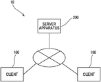
FIG. 1 is a diagram illustrating a schematic configuration of adata management system 10 according to the present exemplary embodiment. - As illustrated in
FIG. 1 , thedata management system 10 is configured to includeclients 100 and aserver apparatus 200 that are connected to each other via communication means such as a network. As the communication means, as will be described later, various networks such as the Internet or Ethernet (registered trademark) may be used. InFIG. 1 , twoclients 100 and asingle server apparatus 200 are illustrated, but the number thereof is not limited thereto. -
FIG. 2 is a block diagram illustrating a hardware configuration of theclient 100. - As illustrated in
FIG. 2 , theclient 100 includes a central processing unit (CPU) 101, a read only memory (ROM) 102, a random access memory (RAM) 103, astorage 104, acommunication interface 105, aninput unit 106, and adisplay unit 107. The respective constituent elements are communicably connected to each other via abus 108. - The
CPU 101 is a central operation processing unit, and executes various programs or controls each unit. In other words, theCPU 101 reads a program from theROM 102 or thestorage 104, and executes the program with theRAM 103 as a work region. TheCPU 101 performs control of each constituent element and various operation processes according to the program recorded on theROM 102 or thestorage 104. In the present exemplary embodiment, programs are stored in theROM 102 or thestorage 104. - The
ROM 102 stores various programs and various pieces of data. TheRAM 103 is a work region and temporarily stores programs or data. Thestorage 104 is configured with a hard disk drive (HDD) or a solid state drive (SSD), and stores various programs including an operating system, and various pieces of data. - The
communication interface 105 is an interface used to perform communication with other apparatuses such as theserver apparatus 200, and employs a standard such as the Internet, Ethernet (registered trademark), FDDI, or Wi-Fi (registered trademark). - The
input unit 106 includes a pointing device such as a mouse, and a keyboard, and is used to perform various inputs. - The
display unit 107 is, for example, a liquid crystal display, and displays various pieces of information. Thedisplay unit 107 may function as theinput unit 106 by using a touch panel type. -
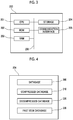
FIG. 3 is a block diagram illustrating a hardware configuration of theserver apparatus 200. - As illustrated in
FIG. 3 , theserver apparatus 200 includes aCPU 201, aROM 202, aRAM 203, astorage 204, and acommunication interface 205. The respective constituent elements are communicably connected to each other via abus 206. - The
CPU 201 is a central operation processing unit, and executes various programs or controls each unit. In other words, theCPU 201 reads a program from theROM 202 or thestorage 204, and executes the program with theRAM 203 as a work region. TheCPU 201 performs control of each constituent element and various operation processes according to the program recorded on theROM 202 or thestorage 204. In the present exemplary embodiment, programs and various databases are stored in theROM 202 or thestorage 204. - The
ROM 202 stores various programs and various pieces of data. TheRAM 203 is a work region and temporarily stores programs or data. Thestorage 204 is configured with an HDD or an SSD, and stores various programs including an operating system, and various pieces of data. - The
communication interface 205 is an interface used to perform communication with other apparatuses such as theclient 100, and employs a standard such as Ethernet (registered trademark), FDDI, or Wi-Fi (registered trademark). - The
server apparatus 200 may be provided with an input unit that includes a pointing device such as a mouse, and a keyboard, and is used to perform various inputs, or a display unit such as a liquid crystal display that displays various pieces of information. - The
storage 204 of theserver apparatus 200 has, as illustrated inFIG. 4 , storage regions as adatabase 300, acompressed database 310, adecompressed database 320, and apast item database 330, and stores various pieces of data. - The
database 300 stores data received by a process reception processing unit 210 (refer toFIG. 9 ) which will be described later, or the types of data stored in processes in a plurality of stages of an item illustrated inFIGS. 5A and 5B and a progress status of each process. - The data stored in the
database 300 is compressed at a predefined timing by a compression processing unit 220 (refer toFIG. 9 ) which will be described later, and is stored in the compresseddatabase 310. - Here, with reference to
FIGS. 5A and 5B , a description will be made of processes in a plurality of stages of an item stored in thedatabase 300. -
FIGS. 5A and 5B are diagrams for describing examples of items. As an item,FIG. 5A illustrates an item example of “purchase”, and illustrates processes in a plurality of stages of the item of “purchase” and data (document) stored in each process. Hereinafter, the item of “purchase” will be simply referred to as a “purchase” item. - This item is configured with a first process “estimate”, a second process “request for approval”, a third process “contract”, a fourth process “delivery”, a fifth process “billing”, and a sixth process “money reception management”, and indicates that work is performed in this order.
- A proposal/introduction document and a written estimate are stored in the first process “estimate”; an approval document is stored in the second process “request for approval”; an order form, Confirmation of order, an application form, a non-disclosure agreement, a basic agreement, and a memorandum are stored in the third process “contract”; a statement of delivery and an inspection document are stored in the fourth process “delivery”; a bill is stored in the fifth process “billing”; and a receipt is stored in the sixth process “money reception management”.
- Data stored in each process is not limited to the above-described data, and other data may be stored.
- “K01” as a management number is assigned to the “purchase” item of the present example. An identical management number is assigned to a “purchase” item having an identical configuration of processes in a plurality of stages among a plurality of different “purchase” items.
- In other words, an identical management number is assigned to a “purchase” item having the same processes and data stored in each process as those of the “purchase” item of the present example. On the other hand, even in a case of a “purchase” item, a separate is assigned to a “purchase” item that is different from the “purchase” item of the present example in terms of different processes and data stored in each process.
- Thus, in a case where a new item is to be registered in the data management system, an operator of the
client 100 selects a corresponding management number from a screen displayed on thedisplay unit 107 via theinput unit 106. In a case where the management number is selected, processes in a plurality of stages and data stored in each process are collectively selected. - The processes in a plurality of stages include an acquisition process of acquiring data in other processes, stored in the compressed database.
- In the present example, for example, the third process “contract” is set to the acquisition process, and the data in the first process “estimate” is set to be acquired in the process.
- As an item,
FIG. 5B illustrates an item example of “audit”, and illustrates processes in a plurality of stages of the item of “audit” and data (document) stored in each process. Hereinafter, the item of “audit” will be simply referred to as an “audit” item. - This item is configured with a first process “document α creation”, a second process “document β creation”, a third process “operation history acquisition”, and a fourth process “submission”, and indicates that work is performed in this order. A document α is stored in the first process “document α creation”; a document β is stored in the second process “document β creation”; a document γ is stored in the third process “operation history acquisition”; and a submitted document is stored in the fourth process “submission”. Data stored in each process is not limited to the above-described data, and other data may be stored.
- “K10” as a management number is assigned to the “audit” item of the present example. An identical management number is assigned to an “audit” item having an identical configuration of processes in a plurality of stages among a plurality of different “audit” item.
- In other words, an identical management number is assigned to an “audit” item having the same processes and data stored in each process as those of the “audit” item of the present example. On the other hand, even in a case of an “audit” item, a separate is assigned to an “audit” item that is different from the “audit” item of the present example in terms of different processes and data stored in each process.
- The processes in a plurality of stages include an acquisition process of acquiring data in other processes, stored in the compressed database.
- In the present example, for example, the third process “operation history acquisition” is set to the acquisition process, and an operation history for a target item corresponding to the “audit” item is set to be acquired.
- With reference to
FIG. 6 , progress statuses of processes stored in thedatabase 300 will be described. -
FIG. 6A illustrates one of the “purchase” items inFIG. 5A , stored in thedatabase 300, and illustrates an example of a progress status of the “purchase” item assigned with “purchase P003” as an item ID. - Specifically,
FIG. 6A illustrates that first creation of the item is performed on Oct. 11, 2018 (category of summary), the first process is started on Oct. 11, 2018 and is finished on Oct. 31, 2018 (category of the first process), and the second process is started on Oct. 31, 2018 (category of the second process). - The start date and time or the end date and time of each process is input by an operator of the
client 100, but is not limited thereto. The start date and time of each process may be set to the next date of the end date of the previous process, and the end date and time of each process may be set to the date on which all data to be stored in the process is stored. - Similarly,
FIG. 6B illustrates one of the “audit” items inFIG. 5B , stored in thedatabase 300, and illustrates an example of a progress status of the “audit” item assigned with “audit P003” as an item ID. - Specifically,
FIG. 6A illustrates that first creation of the item is performed on Oct. 6, 2018 (category of summary), the first process is started on Oct. 6, 2018 and is finished on Oct. 23, 2018 (category of the first process), and the second process is started on Oct. 23, 2018 (category of the second process). - Data received by the process
reception processing unit 210 which will be described later includes an operation history including storage, editing, or reading of the data in thedatabase 300 as illustrated inFIG. 7 . - Thus, the operation history is also compressed at a predefined timing by the
compression processing unit 220, and is stored in the compressed database. - Here, a description will be made of an operation history with reference to
FIG. 7 . - The operation history is divided into categories such as a history ID and an item ID numbered consecutively, the operation date and time, an operator, an operation target, and an operation content, and stores that, for example, in the history ID “H0001”, with respect to the item ID “purchase P001”, Hanako FUJI stored the document “proposal/introduction document.pptx” at 10:07:50 on Jun. 21, 2018.
- It is stored that, in the history ID “H0007”, with respect to the item ID “purchase P002”, taro FUJI edited the document “written estimate.docx” at 15:17:56 on Jul. 31, 2018.
- The operation history is not limited to such categories, and may store other categories.
- The operation history illustrated in
FIG. 7 is compressed for each history and is stored in thecompressed database 310, but is not limited thereto, an operation history may be separately compressed for each item, all operation histories may be compressed for items having an identical management number, that is, operation histories for the identical management number “K01” may be compressed, and all operation histories may be compressed regardless of an item ID. - The
compressed database 310 stores data that is received by the processreception processing unit 210 and is compressed by thecompression processing unit 220. - The decompressed
database 320 stores data decompressed by thedecompression processing unit 230. - The decompressed
database 320 is not limited to a case of being provided in thesame server apparatus 200 as that of thecompressed database 310, and may be provided in theserver apparatus 200 that is different from that of thecompressed database 310. - In other words, the decompressed
database 320 may acquire compressed data stored in thecompressed database 310, and may store the compressed data into the decompresseddatabase 320 provided in theserver apparatus 200 that is different from that of thecompressed database 310, so as to decompress the compressed data. Alternatively, the compressed data may be decompressed in thecompressed database 310, and may then be stored into the decompresseddatabase 320 provided in theserver apparatus 200 that is different from that of thecompressed database 310. Alternatively, the compressed data may be acquired from thecompressed database 310 by anotherserver apparatus 200, so as to be decompressed, and may be stored in the decompresseddatabase 320 provided in a separate server aspect. - As the
server apparatus 200, there may be theserver apparatus 200 with a charge system that charges for acquisition (download) of data and theserver apparatus 200 with a charge system that charges for storage (upload) of data. Theserver apparatus 200 that charges for acquisition of data may be combined with a plurality ofserver apparatuses 200 such that compressed data is acquired without being decompressed, and thus thedata management system 10 that does not make a charge may be built. - The
past item database 330 stores information regarding a past item. - The information regarding a past item includes a progress status of each process of the past item as illustrated in
FIGS. 8A and 8B . - Here, with reference to
FIGS. 8A and 8B , a description will be made of a progress status of a process of a past item stored in thepast item database 330. -
FIG. 8A illustrates examples of progress statuses of item IDs “purchase P001” and “purchase P002” as the “purchase” items inFIG. 5A , stored in thepast item database 330. - Specifically, it is illustrated that first creation of the item with “purchase P001” is performed on Jun. 12, 2018 (category of summary), the first process is started on Jun. 12, 2018 and is finished on Jul. 3, 2018 (category of the first process), the second process is started on Jul. 3, 2018 and is finished on Aug. 6, 2018 (category of the second process), the third process is started on Aug. 6, 2018 and is finished on Sep. 13, 2018 (category of the third process), and the item with “purchase P001” is finished on Oct. 18, 2018 (category of summary).
- Similarly, it is illustrated that first creation of the item with “purchase P002” is performed on Jul. 2, 2018 (category of summary), the first process is started on Jul. 3, 2018 and is finished on Aug. 1, 2018 (category of the first process), the second process is started on Aug. 2, 2018 and is finished on Sep. 3, 2018 (category of the second process), the third process is started on Sep. 3, 2018 and is finished on Oct. 3, 2018 (category of the third process), and the item with “purchase P002” is finished on Nov. 11, 2018 (category of summary).
- Similarly,
FIG. 8B illustrates examples of progress statuses of item IDs “audit P001” and “audit P002” as the “audit” items inFIG. 5B , stored in thepast item database 330. - Specifically, it is illustrated that first creation of the item with “audit P001” is performed on Oct. 5, 2016 (category of summary), the first process is started on Oct. 5, 2016 and is finished on Oct. 20, 2016 (category of the first process), the second process is started on Oct. 20, 2016 and is finished on Nov. 5, 2016 (category of the second process), the third process is started on Nov. 5, 2016 and is finished on Dec. 19, 2016 (category of the third process), and the item with “audit P001” is finished on Jan. 18, 2017 (category of summary).
- Similarly, it is illustrated that first creation of the item with “audit P002” is performed on Oct. 2, 2017 (category of summary), the first process is started on Oct. 2, 2017 and is finished on Oct. 15, 2017 (category of the first process), the second process is started on Oct. 15, 2017 and is finished on Oct. 29, 2017 (category of the second process), the third process is started on Oct. 29, 2017 and is finished on Dec. 18, 2017 (category of the third process), and the item with “audit P002” is finished on Jan. 11, 2018 (category of summary).
- The
server apparatus 200 realizes various functions by using the hardware resources. Functional configurations realized by theserver apparatus 200 will be described. -
FIG. 9 is a block diagram illustrating an example of a functional configuration of theserver apparatus 200. - As illustrated in
FIG. 9 , theserver apparatus 200 includes, as functional configurations, the processreception processing unit 210, thecompression processing unit 220, adecompression processing unit 230, and a progressexpectation processing unit 240. Each functional configuration is realized by theCPU 201 reading a program stored in theROM 202 or thestorage 204 and executing the program. - The process
reception processing unit 210 receives input of data for defining processes in a plurality of stages of an item, that is, information for determining a process needed for each item, input of information for determining data such as a document needed in each process, or input of data in each of processes in a plurality of stages of an item. - In a case where data is received by the process
reception processing unit 210, thecompression processing unit 220 compresses the received data, and stores the data into thecompressed database 310. - A timing at which the
compression processing unit 220 compresses data may be the same time as a timing at which the processreception processing unit 210 receives the data, but is not limited thereto, and may be a timing after a predefined time elapses from reception of data, for example, after a process of receiving the data is completed. - The
decompression processing unit 230 decompresses compressed data stored in thecompressed database 310 at the predefined date and time before an acquisition process is started, and stores the data into the decompresseddatabase 320. As described above, the processes in a plurality of stages include the acquisition process of acquiring data in another process, stored in thecompressed database 310. - Here, the predefined date and time before the acquisition process is started is the date and time expected by the progress
expectation processing unit 240 as will be described later in the present exemplary embodiment. However, the present exemplary embodiment is not limited thereto, and the predefined date and time before the acquisition process is started may be set by an operator of theclient 100 based on the past experience in a case where an item is first created. Alternatively, regarding the predefined date and time before the acquisition process is started, the predefined date and time from the start date and time may be set as a default. - Among past items stored in the
past item database 330, the progressexpectation processing unit 240 expects the predefined date and time by using an average processing time for a common process of a past item that is common to an item in which data is to be acquired through the acquisition process in terms of a process before the acquisition process. - A description will be made of an example of progress expectation with reference to
FIGS. 6A, 6B, 8A, and 8B . -
FIG. 6A illustrates an example of a case where data is acquired. - In the category of the third process in
FIG. 6A , a range of a past item of which an average processing time is obtained among past items is set to “retrieval setting of acquisition scheduled history”. In the present example, an item with the management number “K01” started from January, 2018 to December, 2018 is set as a past item of which an average processing time is obtained. Among the processes in a plurality of stages, a process in which data is stored to be acquired is set as a “data acquisition target”. In the present example, data stored in the first process is set to be acquired. As “data pre-acquisition status”, it is stored that data starts to be acquired on Dec. 1, 2018, that is, starts to be decompressed by thedecompression processing unit 230, and is currently acquired. The date and time of the progress expected by the progressexpectation processing unit 240 is stored in “progress expectation executed date and time”. In a case where the “data pre-acquisition status” does not reach the date and time expected by the progressexpectation processing unit 240, data is not acquired. - Here, in the present example, data stored in the first process of the identical item ID “purchase P003” is acquired in the third process.
- This is because data is created in the subsequent third process by referring to the data stored in the previous first process. The time for which data not compressed is stored in the
server apparatus 200 is reduced as much as possible compared with a case where data stored in the first process is preserved without being compressed, and thus a data usage amount in theserver apparatus 200 is reduced. In a case where the data usage amount is reduced, this can contribute to a reduction of a charge. - The progress
expectation processing unit 240 expects the date and time at which the third process is started based on the “retrieval setting of acquisition scheduled history” and the “data acquisition target”. - Specifically, first, a past item corresponding to the “retrieval setting of acquisition scheduled history” is determined from the
past item database 330. In the present example, a description will be made assuming that the item IDs “purchase P001” and “purchase P002” inFIG. 8A correspond thereto. - The date and time at which the third process of the determined past item is started is calculated. In the present example, in the item ID “purchase P001”, a processing time is 53 days from Jun. 12, 2018 on which the first process is started to Aug. 6, 2018 on which the second process is finished. In the item ID “purchase P002”, a processing time is 63 days from Jun. 3, 2018 on which the first process is started to Sep. 3, 2018 on which the second process is finished. Thus, an average processing time is 58 days.
- The start date and time of the first process of the item ID “purchase P003” is Oct. 11, 2018, and thus the end of the second process, that is, the expected start date and time of the third process is Dec. 8, 2018 after 63 days.
- Thus, the
decompression processing unit 230 decompresses the data stored in the “first process” stored in thecompressed database 310 up to the expected start date and time. - In the present example, the data is decompressed a predefined time before the expected start date and time, for example, a week before, but is not limited thereto, and the time required for decompression may be calculated based on a capacity of compressed data stored in the
compressed database 310, and decompression may be started the calculated required time before. - With this configuration, the time required for decompression can be accurately calculated compared with decompression is started a predefined time before, and thus it is possible to reduce the time required to store decompressed data into the decompressed
database 320. - In the present example, the expected start date and time is determined based on an average processing time, but is not limited thereto, and the expected start date and time may be determined based on a past item in which a processing time is shorted, that is, 53 days in “purchase P001”.
- With this configuration, even in an item in which a processing time is shorter than an average processing time, decompression processing is finished at the time of starting of a process, and thus the process can be started without wait for the decompression processing.
- As a time for which decompressed data stored in the decompressed
database 320 becomes longer, a charge for using theserver apparatus 200 is frequently increased, and thus it is preferable to reduce a time for which the decompressed data is stored in the decompresseddatabase 320. Thus, in a case where an average processing time is determined, a more accurate average processing time may be determined except for a past item in which a processing time is shorted and a past item in which a processing time is longest. - In a case where an average processing time cannot be calculated, for example, in a case where there is only a single past item corresponding to an “aspect time period”, a progress status of the past item may be set as the expected start date and time, and may be set by an operator of the
client 100. -
FIG. 6B illustrates an example of a case where history data regarding an operation history is acquired. In the category of the third process inFIG. 6B , a range of a past item of which an average processing time is obtained among past items is set to “retrieval setting of acquisition scheduled history”. In the present example, an item with the management number “K10” started from January, 2016 to December, 2018 is set as a past item of which an average processing time is obtained. History data to be acquired is set as a “history acquisition target”. In the present example, history data stored in the management number “K01” finished in June, 2018 starting from January, 2018 is set to be acquired. As a “history pre-acquisition status”, it is stored that history is not acquired, that is, decompression is not started by thedecompression processing unit 230. The date and time of the progress expected by the progressexpectation processing unit 240 is stored in “progress expectation executed date and time”. - Here, in the item ID “audit P003”, unlike in
FIG. 6A , history data stored in the management number “K01” that is another item is acquired. - This is because the present item is a process of auditing other items, and thus history data of another audit target item is acquired.
- The progress
expectation processing unit 240 expects the date and time at which the third process is started based on the “retrieval setting of acquisition scheduled history” and the “history acquisition target”. - Specifically, first, a past item corresponding to the “retrieval setting of acquisition scheduled history” is determined from the
past item database 330. In the present example, a description will be made assuming that the item IDs “audit P001” and “audit P002” inFIG. 8B correspond thereto. - The date and time at which the third process of the determined past item is started is calculated. In the present example, in the item ID “audit P001”, a processing time is 31 days from Oct. 5, 2016 on which the first process is started to Nov. 5, 2016 on which the second process is finished. In the item ID “audit P002”, a processing time is 27 days from Oct. 2, 2017 on which the first process is started to Oct. 29, 2017 on which the second process is finished. Thus, an average processing time is 29 days.
- The start date and time of the first process of the item ID “audit P003” is Oct. 6, 2018, and thus the end of the second process, that is, the expected start date and time of the third process is Nov. 4, 2018 after 29 days.
- Thus, the
decompression processing unit 230 decompresses the data stored in the management number “K01” stored in thecompressed database 310 up to the expected start date and time. - Next, a description will be made of an operation of the
data management system 10. -
FIG. 10 is a flowchart illustrating a flow of progress expectation processing performed by thedata management system 10. TheCPU 201 reads a program from theROM 202 or thestorage 204, develops the program into theRAM 203, and executes the program, and thus the progress expectation processing is performed. - First, in step S100, the CPU 201 (progress expectation processing unit 240) determines whether or not the progress expectation executed date and time is unset. In other words, it is determined whether or not the progress expectation processing is not performed yet, and the field of the progress expectation executed date and time of the past item database illustrated in
FIG. 6 is “unset” (not illustrated). In a case where it is determined that the progress expectation executed date and time is not unset (step S100: NO), that is, in a case where the progress expectation executed date and time is set, the flow proceeds to the subsequent step S101. In a case where it is determined that the progress expectation executed date and time is unset (step S100: YES), the flow proceeds to the subsequent step S102. - The determination process in step S100 is performed every predefined time.
- In step S101, the
CPU 201 determines whether or not the progress expectation executed date and time determined in step S100 is progress expectation at the time corresponding to Y hours or more before. In other words, it is determined whether or not the progress expectation executed date and time is old information. In a case where it is determined that the progress expectation executed date and time determined is not progress expectation at the time corresponding to Y hours or more before (step S101: NO), the processing is finished. On the other hand, in a case where it is determined that the progress expectation executed date and time determined is progress expectation at the time corresponding to Y hours or more before (step S101: YES), the flow proceeds to the subsequent step S102. - In step S102, the
CPU 201 acquires information regarding a management number of a past item matching a management number of an item in which progress expectation is executed, from the past item database. Here, the acquired information of the past item includes information regarding the start date and time and the end date and time of each process of the past item. The flow proceeds to the subsequent step S103. - In step S103, the
CPU 201 calculates a difference between the start date and time of the past item and the end date and time of a process before the acquisition process. The flow proceeds to the subsequent step S104. - In step S104, the
CPU 201 calculates an average value (average processing time) of the difference calculated in step S103. The flow proceeds to the subsequent step S105. - In step S105, the
CPU 201 calculates the start date and time of the acquisition process based on the average value (average processing time) calculated in step S104. The flow proceeds to the subsequent step S106. - In step S106, the
CPU 201 sets the start date and time of the acquisition process, and sets the current date and time (the date and time at which progress is expected) to the progress expectation executed date and time (refer toFIGS. 6A and 6B ). The processing is finished. -
FIG. 11 is a flowchart illustrating an example of a flow of decompression processing performed by thedata management system 10. In the present example, a description will be made by using an example of history data decompression processing. TheCPU 201 reads a program from theROM 202 or thestorage 204, develops the program into theRAM 203, and executes the program, and thus the decompression processing is performed. - First, the CPU 201 (decompression processing unit 230) acquires items of which the expected start date and time set in step S106 in
FIG. 10 is within a week from the current date and time in step S200. The flow proceeds to the subsequent step S201. - In step S202, it is determined whether or not a history pre-acquisition status of the
database 300 is unacquired (refer toFIG. 6B ). In a case where the history pre-acquisition status is not unacquired, that is, is being acquired or has been acquired, the processing is finished. In a case where the history pre-acquisition status is unacquired, the flow proceeds to the subsequent step S202. - In step S202, the
CPU 201 changes the history pre-acquisition status to “being acquired”. The flow proceeds to the subsequent step S203. - In step S203, the
CPU 201 acquires compressed history data from thecompressed database 310. The flow proceeds to the subsequent step S204. - In step S204, the
CPU 201 decompresses the compressed history data acquired in step S203. The flow proceeds to the subsequent step S205. - In step S205, the
CPU 201 stores the history data decompressed in step S204 into the decompresseddatabase 320. The flow proceeds to the subsequent step S206. - In step S206, the
CPU 201 changes the history pre-acquisition status of thedatabase 300 to “acquired”. The processing is finished. - In the exemplary embodiment, the progress expectation processing and the decompression processing executed by the
CPU 201 reading software (program) may be executed by various processors other than theCPU 201. Examples of the processors in this case may include a programmable logic device (PLD) such as a field-programmable gate array (FPGA) of which a circuit configuration is changeable after being manufactured, and a dedicated electric circuit that is a processor having a circuit configuration specially designed in order to execute specific processing, such as an application specific integrated circuit (ASIC). The progress expectation processing and the decompression processing may be executed by one of the various processors, and may be executed by a combination of identical types or different types of two or more processors (for example, a combination of a plurality of FPGAs or a combination of a CPU and an FPGA). A hardware structure of each of the various processors is, for example, an electric circuit in which circuit elements such as semiconductor elements are combined with each other. - In the exemplary embodiment, a description has been made of an aspect in which the programs for the progress expectation processing and the decompression processing are stored (installed) in the
ROM 202 or thestorage 204 in advance, but this is only an example. The program may be provided in a form of being recorded on recording media such as a compact disk read only memory (CD-ROM), a digital versatile disk read only memory (DVD-ROM), and a Universal Serial Bus (USB) memory. The program may be provided in a form of being downloaded from an external device via a network. - The present invention is not limited to the exemplary embodiment, and may be variously modified or altered within the scope without departing from the spirit of the invention.
- An access history to data in each process of a past item may be stored in the
past item database 330, and thedecompression processing unit 230 may extract data to be decompressed from compressed data stored in thecompressed database 310 based on the access history. - In other words, for example, even in a case where the “data acquisition target” (refer to
FIG. 6A ) is the “first process”, data accessed in a past item is decompressed instead of decompressing all data stored in the first process. - With this configuration, only necessary data can be decompressed instead of all data such that an amount of decompressed data can be reduced, and thus it is possible to reduce a decompression time or a storage region of the
server apparatus 200 preserving decompressed data. - An upper limit of an amount of data extracted in the monthly unit may be set, and decompressed data may be extracted from the decompressed
database 320 separately for each month. - With this configuration, even in a case where a charge for use of the
server apparatus 200 is made at a stage corresponding to an amount of data extracted in the monthly unit, it is possible to suppress an upper limit of a charge for use of theserver apparatus 200 by averaging an extraction amount. - The foregoing description of the exemplary embodiments of the present invention has been provided for the purposes of illustration and description. It is not intended to be exhaustive or to limit the invention to the precise forms disclosed. Obviously, many modifications and variations will be apparent to practitioners skilled in the art. The embodiments were chosen and described in order to best explain the principles of the invention and its practical applications, thereby enabling others skilled in the art to understand the invention for various embodiments and with the various modifications as are suited to the particular use contemplated. It is intended that the scope of the invention be defined by the following claims and their equivalents.
Claims (20)
Applications Claiming Priority (3)
| Application Number | Priority Date | Filing Date | Title |
|---|---|---|---|
| JP2019051941A JP7326794B2 (en) | 2019-03-19 | 2019-03-19 | data management system |
| JPJP2019-051941 | 2019-03-19 | ||
| JP2019-051941 | 2019-03-19 |
Publications (2)
| Publication Number | Publication Date |
|---|---|
| US20200301904A1 true US20200301904A1 (en) | 2020-09-24 |
| US11372835B2 US11372835B2 (en) | 2022-06-28 |
Family
ID=72514438
Family Applications (1)
| Application Number | Title | Priority Date | Filing Date |
|---|---|---|---|
| US16/533,726 Active 2040-04-22 US11372835B2 (en) | 2019-03-19 | 2019-08-06 | Data management system |
Country Status (2)
| Country | Link |
|---|---|
| US (1) | US11372835B2 (en) |
| JP (1) | JP7326794B2 (en) |
Cited By (1)
| Publication number | Priority date | Publication date | Assignee | Title |
|---|---|---|---|---|
| US10992766B2 (en) * | 2017-04-27 | 2021-04-27 | Chicago Mercantile Exchange Inc. | Adaptive compression of stored data |
Family Cites Families (16)
| Publication number | Priority date | Publication date | Assignee | Title |
|---|---|---|---|---|
| US5253275A (en) * | 1991-01-07 | 1993-10-12 | H. Lee Browne | Audio and video transmission and receiving system |
| US6813384B1 (en) * | 1999-11-10 | 2004-11-02 | Intel Corporation | Indexing wavelet compressed video for efficient data handling |
| JP2001299307A (en) | 2000-04-28 | 2001-10-30 | Matsushita Refrig Co Ltd | Freezing and thawing chamber detecting temperature of goods |
| JP2004013632A (en) | 2002-06-07 | 2004-01-15 | Canon Inc | Electronic conference system and computer-readable storage medium |
| JP2004133497A (en) * | 2002-10-08 | 2004-04-30 | Hitachi Ltd | Method for electronic commerce |
| JP4811076B2 (en) | 2006-03-22 | 2011-11-09 | 富士通株式会社 | Log data compression program and method |
| JP4758330B2 (en) | 2006-12-08 | 2011-08-24 | 三菱電機株式会社 | Power plant operating history data management device |
| JP2009122791A (en) | 2007-11-13 | 2009-06-04 | Hitachi Software Eng Co Ltd | End-of-work prediction system in work flow |
| JP5087724B2 (en) | 2008-08-06 | 2012-12-05 | 偉剛 許 | Image compression apparatus, image expansion apparatus, image compression program, and image expansion program |
| ITTV20090017A1 (en) * | 2009-02-17 | 2010-08-18 | B & B Holding S R L | METHOD AND SYSTEM FOR THE EXCHANGE OF DIGITAL DOCUMENTS. |
| US8509237B2 (en) * | 2009-06-26 | 2013-08-13 | Wisconsin Alumni Research Foundation | Architecture and system for coordinated network-wide redundancy elimination |
| JP5285683B2 (en) * | 2010-12-01 | 2013-09-11 | シャープ株式会社 | Image processing apparatus and image processing method |
| JP2013045208A (en) * | 2011-08-23 | 2013-03-04 | Fujitsu Ltd | Data generation method, device and program, retrieval processing method, and device and program |
| JP6306275B1 (en) * | 2016-10-20 | 2018-04-04 | 楽天株式会社 | Information processing apparatus, information processing method, program, and storage medium |
| US10943311B1 (en) * | 2017-09-29 | 2021-03-09 | Square, Inc. | Order fulfillment and tracking systems and methods |
| JP6972934B2 (en) * | 2017-11-02 | 2021-11-24 | コニカミノルタ株式会社 | Data receiver, control method of data receiver, program, data transmission / reception system and data transmission device |
-
2019
- 2019-03-19 JP JP2019051941A patent/JP7326794B2/en active Active
- 2019-08-06 US US16/533,726 patent/US11372835B2/en active Active
Cited By (6)
| Publication number | Priority date | Publication date | Assignee | Title |
|---|---|---|---|---|
| US10992766B2 (en) * | 2017-04-27 | 2021-04-27 | Chicago Mercantile Exchange Inc. | Adaptive compression of stored data |
| US11218560B2 (en) | 2017-04-27 | 2022-01-04 | Chicago Mercantile Exchange Inc. | Adaptive compression of stored data |
| US11399083B2 (en) | 2017-04-27 | 2022-07-26 | Chicago Mercantile Exchange Inc. | Adaptive compression of stored data |
| US11539811B2 (en) | 2017-04-27 | 2022-12-27 | Chicago Mercantile Exchange Inc. | Adaptive compression of stored data |
| US11700316B2 (en) | 2017-04-27 | 2023-07-11 | Chicago Mercantile Exchange Inc. | Adaptive compression of stored data |
| US11895211B2 (en) | 2017-04-27 | 2024-02-06 | Chicago Mercantile Exchange Inc. | Adaptive compression of stored data |
Also Published As
| Publication number | Publication date |
|---|---|
| US11372835B2 (en) | 2022-06-28 |
| JP2020154649A (en) | 2020-09-24 |
| JP7326794B2 (en) | 2023-08-16 |
Similar Documents
| Publication | Publication Date | Title |
|---|---|---|
| US10366053B1 (en) | Consistent randomized record-level splitting of machine learning data | |
| US10860337B2 (en) | Method, device and user terminal for loading application | |
| US9081838B2 (en) | Methods, apparatuses, and computer program products for database record recovery | |
| US11372835B2 (en) | Data management system | |
| US11030172B2 (en) | Database archiving method and device for creating index information and method and device of retrieving archived database including index information | |
| US10698608B2 (en) | Method, apparatus and computer storage medium for data input and output | |
| CN111258819A (en) | Data acquisition method, device and system for MySQL database backup file | |
| CN111625580A (en) | Data processing method, device and equipment | |
| CN112631676A (en) | Code dynamic loading method and device and computer readable storage medium | |
| US20060149725A1 (en) | Managing electronic documents | |
| CN110633304B (en) | Combined feature screening method, device, computer equipment and storage medium | |
| CN110096478B (en) | Document index generation method and device | |
| WO2020242656A1 (en) | Adaptive storage management policies for computing devices | |
| US11295124B2 (en) | Methods and systems for automatically detecting the source of the content of a scanned document | |
| US20220066983A1 (en) | System and method for the automated scheduling and retrieval of archived data | |
| WO2019019737A1 (en) | Product data processing system and method, server and storage medium | |
| US11593391B2 (en) | Determination of result data for small multiples based on subsets of a data set | |
| CN114218455A (en) | Method, device, equipment and medium for quickly reading files | |
| US11023226B2 (en) | Dynamic data ingestion | |
| WO2021072776A1 (en) | Data merging method and apparatus, electronic device, and storage medium | |
| US20200293496A1 (en) | Information processing apparatus and non-transitory computer readable medium | |
| CN112148721A (en) | Data checking method and device, electronic equipment and storage medium | |
| JP6927771B2 (en) | Sales management equipment, sales management methods, and sales management programs | |
| US9501534B1 (en) | Extreme value computation | |
| CN113360539B (en) | Market subscription-based subscription information pushing method, device, equipment and medium |
Legal Events
| Date | Code | Title | Description |
|---|---|---|---|
| AS | Assignment |
Owner name: FUJI XEROX CO., LTD., JAPAN Free format text: ASSIGNMENT OF ASSIGNORS INTEREST;ASSIGNOR:HIRATA, MOTOHARU;REEL/FRAME:049981/0437 Effective date: 20190606 |
|
| FEPP | Fee payment procedure |
Free format text: ENTITY STATUS SET TO UNDISCOUNTED (ORIGINAL EVENT CODE: BIG.); ENTITY STATUS OF PATENT OWNER: LARGE ENTITY |
|
| AS | Assignment |
Owner name: FUJIFILM BUSINESS INNOVATION CORP., JAPAN Free format text: CHANGE OF NAME;ASSIGNOR:FUJI XEROX CO., LTD.;REEL/FRAME:056237/0131 Effective date: 20210401 |
|
| STPP | Information on status: patent application and granting procedure in general |
Free format text: NON FINAL ACTION COUNTED, NOT YET MAILED |
|
| STPP | Information on status: patent application and granting procedure in general |
Free format text: NON FINAL ACTION MAILED |
|
| STPP | Information on status: patent application and granting procedure in general |
Free format text: RESPONSE TO NON-FINAL OFFICE ACTION ENTERED AND FORWARDED TO EXAMINER |
|
| STPP | Information on status: patent application and granting procedure in general |
Free format text: FINAL REJECTION MAILED |
|
| STPP | Information on status: patent application and granting procedure in general |
Free format text: NOTICE OF ALLOWANCE MAILED -- APPLICATION RECEIVED IN OFFICE OF PUBLICATIONS |
|
| STPP | Information on status: patent application and granting procedure in general |
Free format text: PUBLICATIONS -- ISSUE FEE PAYMENT VERIFIED |
|
| STCF | Information on status: patent grant |
Free format text: PATENTED CASE |