US20180098583A1 - Force grounding wristband for haptic glove - Google Patents
Force grounding wristband for haptic glove Download PDFInfo
- Publication number
- US20180098583A1 US20180098583A1 US15/291,944 US201615291944A US2018098583A1 US 20180098583 A1 US20180098583 A1 US 20180098583A1 US 201615291944 A US201615291944 A US 201615291944A US 2018098583 A1 US2018098583 A1 US 2018098583A1
- Authority
- US
- United States
- Prior art keywords
- force
- force distribution
- wristband
- wrist
- tendon
- Prior art date
- Legal status (The legal status is an assumption and is not a legal conclusion. Google has not performed a legal analysis and makes no representation as to the accuracy of the status listed.)
- Abandoned
Links
Images
Classifications
-
- G—PHYSICS
- G06—COMPUTING; CALCULATING OR COUNTING
- G06F—ELECTRIC DIGITAL DATA PROCESSING
- G06F3/00—Input arrangements for transferring data to be processed into a form capable of being handled by the computer; Output arrangements for transferring data from processing unit to output unit, e.g. interface arrangements
- G06F3/01—Input arrangements or combined input and output arrangements for interaction between user and computer
- G06F3/011—Arrangements for interaction with the human body, e.g. for user immersion in virtual reality
- G06F3/014—Hand-worn input/output arrangements, e.g. data gloves
-
- A—HUMAN NECESSITIES
- A41—WEARING APPAREL
- A41D—OUTERWEAR; PROTECTIVE GARMENTS; ACCESSORIES
- A41D19/00—Gloves
- A41D19/0024—Gloves with accessories
-
- G—PHYSICS
- G06—COMPUTING; CALCULATING OR COUNTING
- G06F—ELECTRIC DIGITAL DATA PROCESSING
- G06F3/00—Input arrangements for transferring data to be processed into a form capable of being handled by the computer; Output arrangements for transferring data from processing unit to output unit, e.g. interface arrangements
- G06F3/01—Input arrangements or combined input and output arrangements for interaction between user and computer
- G06F3/016—Input arrangements with force or tactile feedback as computer generated output to the user
-
- A—HUMAN NECESSITIES
- A41—WEARING APPAREL
- A41D—OUTERWEAR; PROTECTIVE GARMENTS; ACCESSORIES
- A41D19/00—Gloves
- A41D19/0034—Retaining means
-
- G—PHYSICS
- G06—COMPUTING; CALCULATING OR COUNTING
- G06F—ELECTRIC DIGITAL DATA PROCESSING
- G06F3/00—Input arrangements for transferring data to be processed into a form capable of being handled by the computer; Output arrangements for transferring data from processing unit to output unit, e.g. interface arrangements
- G06F3/14—Digital output to display device ; Cooperation and interconnection of the display device with other functional units
Definitions
- the present disclosure generally relates to virtual reality systems, and specifically relates to a wristband for grounding forces generated by a haptic glove.
- VR systems typically provide multiple forms of sensory output, such as a head-mounted display and headphones, which operate together to create the illusion that a user is immersed in a virtual world.
- a VR system can also include an input device such as a haptic glove that can be used to detect the position, acceleration, orientation, or some combination thereof of the user's hand and uses the information as input. The input can then be used to move a corresponding item in the virtual world (e.g., a hand or other appendage belonging to a character in the virtual world) when the VR system detects movement of the haptic glove in the real world.
- a haptic glove can also be used to facilitate interactions with other objects in the virtual world. For example, the VR system can allow the user to use the haptic glove to manipulate virtual objects by touching them, picking them up, and moving them.
- a haptic glove may be used in a mixed reality (MR) system.
- a MR system combines virtual elements with elements from physical world (e.g., a live video feed).
- a MR system may be an augmented reality (AR) system.
- AR augmented reality
- An example of an AR system is a display which overlays virtual objects on a live video feed. Virtual elements displayed in the AR may correspond to physical phenomena detected by the AR system (e.g., a virtual representation a magnetic field).
- the haptic glove may be used to interact with virtual objects or physical objects in an AR system.
- the force ground device is part of a haptic glove.
- the force ground device includes one or more finger sheaths, one or more tendons, and one or more actuators.
- the one or more finger sheaths are configured to enclose a finger of a user of the force grounding device.
- the one or more tendons connect to respective finger sheaths, and each tendon may have a first end and a second end where the first end couples to the respective finger sheath.
- the one or more actuators are coupled to the second end of respective tendons, and are configured to produce tension in the respective tendons.
- the force ground device may also include a wristband coupled to the one or more actuators.
- the wrist band is configured to ground forces from the one or more actuators to a wrist of the user.
- the wristband may include one or more force distribution segments, one or more adjustable strips, one or more tension adjustment mechanism, or some combination thereof.
- the wristband may include one or more force distribution segments that are inflexible in directions parallel to a surface of a wrist.
- the first force distribution band may distribute forces on the wristband from the one or more actuators to a side of the wrist.
- a first force distribution segment may be adjacent to an ulna bone of the wrist and a second force distribution segment may be adjacent to a radius bone of the wrist.
- the wristband may also include one or more adjustable strips.
- the adjustable strips may be coupled to the one or more force distribution segments.
- the one or more tension adjustment mechanisms may couple to the adjustable strips.
- Each tension adjustment mechanisms may be configured to adjust tension in and/or the length of adjustable strips to which it is coupled.
- a tension adjustment mechanism adjacent to the posterior of the user's wrist may couple to two adjustable strips which each couple to a respective force distribution segment.
- the wristband further comprises an anterior band, which may couple between two force distribution segments.
- the one or more adjustable strips may each include one or more wristband tendons.
- the wristband tendons may couple between one of the force distribution segments and one of the tension adjustment mechanisms.
- a tension adjustment mechanism may be configured to increase the tension in an adjustable strip by partially withdrawing the one or more tendons corresponding to the adjustable strip into itself. The tension adjustment mechanism allows a user to manually adjust the tension in the wristband by operating as a ratcheting mechanism.
- each of the one or more force distribution segments may include a plurality of interconnected rigid links.
- each of the one or more force distribution segments includes a mesh and an elastic strip.
- the elastic strip is positioned between the wrist and the mesh.
- the elastic strip may be composed of neoprene and the mesh may be a Milanese mesh.
- the one or more force distribution segments are flexible in a first direction perpendicular to the surface of the wrist.
- the one or more finger sheaths may include a thumb sheath that encloses the thumb of a user.
- the thumb sheath may couples to thumb tendon, which, in turn, couples to a thumb tendon.
- a thumb tension adjustment mechanism on the wristband may be configured to allow a user to adjust the default tension in the thumb tendon.
- FIG. 1 is a block diagram of a system environment, in accordance with an embodiment.
- FIG. 2 illustrates a plan view of a haptic glove, in accordance with an embodiment.
- FIG. 3 illustrates a plan view of a haptic glove with an alternate tendon configuration, in accordance with an embodiment.
- FIG. 4 illustrates a plan view of a wristband with wires for tension adjustment, in accordance with an embodiment.
- FIG. 5A illustrates a cross-section of a wristband with force distribution segments that are each continuous elements, according to an embodiment.
- FIG. 5B illustrates a cross-section of a wristband including series of links, according to an embodiment.
- FIG. 5C illustrates a cross-section of a wristband including meshes, according to an embodiment.
- FIG. 5D illustrates a cross-section of a wristband including hinged segments, according to an embodiment.
- a haptic glove may apply force to a user's hand to simulate a user's interaction with a virtual object.
- the system may detect that a user has reached out to grab a virtual object. This may be detected by sensors integrated into a haptic glove, sensors external to a haptic glove, or some combination thereof.
- the glove may generate an opposing force that resists the closing of the hand. In this way, the haptic glove simulates the experience of grasping the virtual object.
- the haptic glove may also produce force feedback corresponding to a real-world machine controlled by the user.
- the forces generated by the haptic glove may correspond to forces and/or torques applied by a motor or system of motors in, for example, heavy machinery (e.g., an excavator), a robotic surgery system, a telerobotic system, or some combination thereof.
- heavy machinery e.g., an excavator
- robotic surgery system e.g., a robotic surgery system
- telerobotic system e.g., a telerobotic system
- the haptic glove may apply forces to the user's hand via one or more tendons adjacent to the back of the user's hand (i.e., the posterior side of the hand).
- a tendon may connect to an anchor point and to the posterior side of a user's finger. By modulating tension in this tendon by an actuator, the tendon may produce a force resisting the closing of the user's hand, thereby simulating the normal forces of a virtual object grasped by the user.
- forces on the anchor point may cause the haptic glove to deform, shift its position on the user's hand, or produce uncomfortable, irritating forces on the user's hand.
- a tension in the tendon may produce an undesirable deformation of the fabric around the anchor point.
- Deformation of the haptic glove is undesirable because, as tension in a tendon is repeatedly applied and released, the glove may repeatedly deform and shift along the surface of the user's hand. Friction produced by this repeated movement may irritate the user's hand. Furthermore, if tension in the tendon causes the anchor point's position on the user's hand to shift significantly, in order to produce sufficient tension, the tendon may need to be shortened further than it would if the anchor point's position was invariant. Accordingly, it is advantageous for an anchor point of a tendon system to, as close as practicable, remain fixed to the user's hand and/or wrist. That is, the anchor point should not move relative to the user's hand or deform the haptic glove when a force is applied. Such an anchor point is referred to herein as a “grounded” anchor.
- a haptic glove that grounds the forces from tensioned tendons to a wristband may resolve the aforementioned problems.
- the wristband distributes the forces from the tendons to the ulnar and radial sides of the wrist (i.e., the bony portions on the side of the wrist).
- the interface between the sides of the wrist and wristband may provide lateral stiffness so that wristband remains fixed to the wrist.
- Tension in the wristband produces compressive force between the wristband and the sides of the user's wrist. This compressive force increases the lateral stiffness between the sides of the user's wrist and the wristband of the haptic glove.
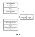
- FIG. 1 is a block diagram of a system environment 100 in which a haptic interface garment 140 operates.
- the system environment 100 may be, for example, a VR, MR, or AR system. In some embodiments, the system environment 100 is capable of alternating between operating as a VR, an MR, and an AR system, or some subset thereof.
- the system environment 100 shown in FIG. 1 comprises a head-mounted display (HMD) 110 and a haptic interface garment 140 that are both coupled to a console 170 . While FIG. 1 shows an example system environment 100 including one HMD 110 and one haptic interface garment 140 , in other embodiments any number of these components may be included in the system environment 100 .
- HMD head-mounted display
- the system environment 100 may include two haptic interface garments 140 (e.g., one haptic glove for each hand) that are worn by the same user.
- the system environment 100 may include multiple haptic interface garments 140 intended to be worn by multiple users, with each haptic interface garment 140 or each pair of haptic interface garments 140 associated with a different HMD 110 .
- different or additional components may be included in the system environment 100 .
- the HMD 110 is a head-mounted display that presents media to a user. Examples of media presented by the HMD 110 include images, video, audio, or some combination thereof.
- audio is presented via an external device (e.g., speakers or headphones) that receives audio information from the HMD 110 , the console 170 , or both, and presents audio data based on the audio information.
- the HMD 110 may also act as an AR and/or MR headset. In these embodiments, the HMD 110 augments views of a physical, real-world environment with computer-generated elements (e.g., images, video, sound, etc.).
- the HMD 110 includes an electronic display 112 , sensors 114 , and a communication interface 116 . Some embodiments of the HMD 110 have different components than those described here. Similarly, the functions can be distributed among the components in a different manner than is described here.
- the electronic display 112 displays images to the user in accordance with data received from the console 170 .
- the electronic display 112 may comprise a single electronic display 112 or multiple electronic displays 112 (e.g., one display for each eye of a user).
- the sensors 114 include one or more hardware devices that detect spatial and motion information about the HMD 110 .
- Spatial and motion information can include information about the position, orientation, velocity, rotation, and acceleration of the HMD 110 .
- the sensors 114 may include a gyroscope that detects rotation of the user's head while the user is wearing the HMD 110 . This rotation information can then be used (e.g., by the engine 174 ) to adjust the images displayed on the electronic display 112 .
- the communication interface 116 enables input and output to the console 170 .
- the communication interface 116 is a bus, such as High-Definition Multimedia Interface (HDMI), Universal Serial Bus (USB), Video Graphics Array (VGA), Digital Visual Interface (DVI), DisplayPortTM, or some combination thereof.
- the communication interface 116 includes several distinct communication buses operating together or independently.
- the communication interface 116 includes wireless connections for sending data collected by the sensors 114 from the HMD 110 to the console 170 but also includes a wired connection (e.g., an HDMI or DVI connection) that receives audio/visual data to be rendered on the electronic display 112 .
- a wired connection e.g., an HDMI or DVI connection
- the haptic interface garment 140 is a wearable device for receiving haptic input or producing haptic output.
- the haptic interface garment 140 may be configured to be worn on a portion of a user's body, such as the user's hand (e.g., a glove).
- the haptic interface garment 140 may collect information about the portion of the user's body that can be used as input for virtual reality applications 172 executing on the console 170 .
- the haptic interface garment 140 includes a haptic feedback mechanism 142 , sensors 144 , and a communication interface 146 .
- Some embodiments of the haptic interface garment 140 have different components than those described here, e.g., the haptic interface garment 140 may include additional components that are not shown in FIG. 1 , such as a power source (e.g., an integrated battery, a connection to an external power source, a container containing compressed air, or some combination thereof).
- a power source e.g., an integrated battery, a connection to an
- the haptic feedback mechanism 142 provides haptic feedback to the user by directing the portion of the user's body to move in a particular way or in a particular direction or preventing the portion of the user's body from moving in certain directions or in certain ways.
- the haptic feedback mechanism 142 includes a tendon system to apply force to the haptic interface garment 140 . Transducers of the tendon system may apply forces on portions of the user's body. By applying forces to the user's body, the tendon system may move a portion of the user's body apply torque to a joint of a user's body, or produce tactile sensation for the user.
- Various embodiments of the haptic feedback mechanism 142 are described in conjunction with FIGS. 2-5D .
- the sensors 144 include one or more hardware devices that detect spatial information for the haptic interface garment 140 .
- the spatial information may include information about position, orientation, velocity, rotation, and acceleration, or some combination thereof.
- the spatial information may refer to the entire haptic interface garment 140 , subdivisions of the haptic interface garment 140 , or both.
- sensors 144 may identify positions and orientations of various portions of the glove, such as the fingers, fingertips, knuckles, palm, or wrist.
- the sensors 144 may also detect forces applied by the user to the haptic interface garment 140 .
- the communication interface 146 enables input from and output to the console 170 .
- the communication interface 146 may be a single communication bus, such as USB.
- the communication interface 146 includes several distinct communication buses operating together or independently.
- the communication interface 146 may include separate communication buses for receiving control signals for the haptic feedback mechanism 142 and sending data from the sensors 144 to the console 170 .
- the one or more communication buses of the communication interface 146 may be implemented as wired connections, wireless connections, or some combination thereof.
- the console 170 is a computing device that executes virtual reality applications, augmented reality applications, mixed reality applications, or some combination thereof, to process input data from the sensors 114 and 144 on the HMD 110 and the haptic interface garment 140 and provide output data for the electronic display 112 on the HMD 110 and the haptic feedback mechanism 142 on the haptic interface garment 140 .
- the console 170 or portions thereof, may be integrated with the HMD 110 , the haptic interface garment 140 , or both the HMD 110 and the haptic interface garment 140 .
- the console 170 can be implemented as any kind of computing device, such as an integrated system-on-a-chip, a microcontroller, a desktop or laptop computer, a server computer, a tablet, a smart phone, or other mobile device.
- the console 170 may include components common to typical computing devices, such as a processor, random access memory (RAM), a storage device, a network interface, an I/O interface, and the like.
- the processor may be or include one or more graphics processing units (GPUs), microprocessors, or application specific integrated circuits (ASICs).
- the memory may be or include RAM, ROM, DRAM, SRAM, and MRAM, and may include firmware, such as static data or fixed instructions, BIOS, system functions, configuration data, and other routines used during the operation of the computing device and the processor.
- the memory also provides a storage area for data and instructions associated with applications and data handled by the processor.
- the storage device provides non-volatile, bulk, or long term storage of data or instructions in the computing device.
- the storage device may take the form of a magnetic or solid state disk, tape, CD, DVD, or other reasonably high capacity addressable or serial storage medium. Multiple storage devices may be provided or be available to the computing device. Some of these storage devices may be external to the computing device, such as network storage or cloud-based storage.
- the network interface includes an interface to a network and can be implemented as either a wired or wireless interface.
- the I/O interface interfaces the processor to peripherals (not shown) such as, depending upon the computing device, sensors, displays, cameras, color sensors, microphones, keyboards and USB devices.
- the console 170 further includes applications 172 and an engine 174 .
- An application 172 running on the engine 174 may generate a VR environment, an AR environment, an MR environment, or some combination thereof.
- the applications 172 and the engine 174 are implemented as software modules that are stored on the storage device and executed by the processor.
- Some embodiments of the console 170 include additional or different components than those described in conjunction with FIG. 1 .
- the functions further described below may be distributed among components of the console 170 in a different manner than is described here.
- Each application 172 is a group of instructions that, when executed by a processor, generates virtual reality content for presentation to the user.
- An application 172 may generate content (e.g., VR, MR, or AR content) in response to inputs received from the user via movement of the HMD 110 or the haptic interface garment 140 .
- Examples of applications 172 include gaming applications, conferencing applications, video playback applications, augmented reality application, telerobotic applications, or other suitable applications.
- the engine 174 is a software module that allows the applications 172 to operate in conjunction with the HMD 110 and the haptic interface garment 140 .
- the engine 174 receives information from sensors 114 on the HMD 110 and provides the information to an application 172 . Based on the received information, the engine 174 determines media content to provide to the HMD 110 for presentation to the user via the electronic display 112 or haptic feedback to provide to the haptic interface garment 140 to provide to the user via the haptic feedback mechanism. For example, if the engine 174 receives information from the sensors 114 on the HMD 110 indicating that the user has looked to the left, the engine 174 generates content for the HMD 110 that mirrors the user's movement in a virtual environment.
- the engine 174 receives information from the sensors 144 on the haptic interface garment 140 and provides the information to an application 172 .
- the application 172 can use the information to perform an action within the virtual world of the application 172 . For example, if the engine 174 receives information from the sensors 144 that the user has closed her fingers around a position corresponding to a coffee mug in the virtual environment and raised her hand, a simulated hand in the application 172 picks up the virtual coffee mug and lifts it to a corresponding height.
- the engine 174 may also provide feedback to the user that the action was performed.
- the provided feedback may be visual via the electronic display 112 in the HMD 110 (e.g., displaying the simulated hand as it picks up and lifts the virtual coffee mug) or haptic feedback via the haptic feedback mechanism 142 in the haptic interface garment 140 (e.g., resisting movement of a user's fingers from curling past a certain point to simulate the sensation of touching a solid coffee mug).
- the haptic feedback may also be force feedback from some machine being controlled by the user.
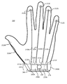
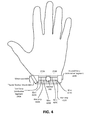
- FIG. 2 illustrates a plan view of a haptic glove 200 , in accordance with an embodiment.
- the haptic glove 200 includes one or more tendons 210 A- 210 E, one or more actuators 215 A- 215 E, one or more finger-tendon anchors 212 A- 212 E, a controller 270 , and a wristband 220 .
- each of the five finger sheaths of the glove 200 corresponds to a respective tendon 210 A- 210 E, a respective actuator 215 A- 215 E, and a respective finger-tendon anchor 212 A- 212 E.
- the haptic glove 200 is shown in an orientation corresponding to posterior view of a user's right hand (i.e., a plan view of the back of the user's hand).
- the tendons 210 A- 210 E are thin elements that each translate force from a respective actuator 215 A- 215 E to a respective finger.
- a tendon 210 A- 210 E may be a wire, string, rod, chord, chain, wire cable, or elastic structure.
- each of the non-thumb tendons 210 B- 210 E runs along the back of the haptic glove 200 (i.e., the side of the haptic glove 200 corresponding to the posterior side of the user's hand) and along the posterior side of its respective finger sheath.
- the tendon 210 A corresponding to the thumb may runs along the side of the thumb.
- the actuators 215 A- 215 E are motors that each tension a respective tendon 210 A- 210 - 210 E.
- Each actuators 215 A- 215 E may include an electromagnetic mechanism (e.g., one or more solenoids), a hydraulic mechanism, a pneumatic mechanism, a piezoelectric mechanism, or a combination thereof.
- an electrical signal is delivered to an actuator 215 A- 215 E, the actuator 215 A- 215 E may apply a force to its respective tendon 210 A- 210 E causing the tendon 210 A- 210 E to be tensioned.
- the haptic glove 200 can apply a force to the fingers of the user's hand. In this way, the haptic glove 200 resists flexion of one or more of the user's fingers or causes extension of the fingers. Resistance to flexion from the haptic glove 200 may be used in conjunction with the display of a virtual object in the HMD 110 to simulate the grasping of the virtual object.
- Each of the finger-tendon anchors 212 A- 212 E is a coupling between a respective tendon 210 A- 210 E and a respective finger sheath of the haptic glove 200 .
- the finger-tendon anchors 212 A- 212 E are located on different portions of the finger sheaths that is depicted in FIG. 2 .
- some or all of the finger-tendon anchors 212 A- 212 E could be adjacent to the distal interphalangeal joints of the fingers, the proximal interphalangeal joints, or both.
- more than one finger-tendon anchor 212 A- 212 E couples between each tendon 210 A- 210 E and the respective finger sheath.
- alternate embodiments use different types of finger-tendon anchors 212 A- 212 E than those illustrated in FIG. 2 .
- Each tendon 210 A- 210 E mechanically couples at a respective first end to a respective finger sheath via a respective finger-tendon anchor 212 A- 212 E.
- the first tendon 210 A couples at the first end to the finger sheath corresponding to the user's thumb (i.e., the “thumb sheath”).
- the other four tendons 210 B- 210 E (i.e., the “finger tendons”) couple at respective first ends to finger sheaths corresponding to the user's index, middle, ring, and “pinky” fingers, respectively.
- Each tendon 210 A- 210 E mechanically couples at a respective second end to a respective actuator 215 A- 215 E.
- the five actuators 215 A- 215 E each couple to the wristband 220 .
- the actuators 215 A- 215 E may be rigidly anchored to the wristband 220 .
- the first actuator 215 A couples to the thumb tendon mount 260 .
- the second actuator 215 B couples to the first force distribution segment 240 A.
- the third actuator 215 C couples to the first adjustable strip 250 A and the fourth and fifth actuators 215 D- 215 E couple to the second adjustable strip 215 E.
- One or more of the actuators 215 A- 215 E may couple to a respective tension adjustment mechanism, and in some embodiments all of the actuators 215 A- 215 E may couple to a respective tension adjustment mechanism. These tension adjustment mechanisms may allow the user to configure the tension on each tendon 210 A- 210 E by adjusting its length to accommodate the shape of the user's hand (e.g., the length of the user's fingers).
- the actuators 215 B- 215 E not corresponding to the thumb all couple at the same part of the wristband 220 .
- the four finger actuators 215 B- 215 E may couple to the first or second adjustable strip 250 A, the first or second force distribution segments 240 A- 240 B, or the ratchet 230 .
- the two actuators 215 B- 215 C corresponding to the index and middle fingers couple to the first adjustable strip 250 A and the two actuators 215 D- 215 E corresponding to the ring and pinky fingers couple the second adjustable strip 250 B.
- one or more of the finger actuators 215 B- 215 E are omitted and one or more of the finger tendons 210 B- 210 E are coupled to the same actuator.
- the four finger tendons 210 B- 210 E may be coupled to a single actuator.
- Other coupling configurations for the actuators 215 A- 215 E and tendons 210 A- 210 E are also possible.
- the controller 270 is an electronic device the controls each of the actuators 215 A- 215 E.
- the controller 270 may receive input the console 170 that may determine setpoint position for each actuator, a force to apply to each actuator, or some combination thereof.
- the controller 270 may include a digital-to-analog converter for converting input from the console 170 to an electrical signal for controlling the actuators 215 A- 215 E.
- the controller 270 may control the actuators 215 A- 215 E individually or control a set of the actuators 215 A- 215 E as a unit.
- a unit of actuators e.g., every other actuator, all the actuators, or any other combination of actuators
- the controller 270 is located at a different location on the haptic glove 200 .
- the functions of the controller 270 are implemented by a device external to but communicatively coupled to the haptic glove 200 (e.g., the console 170 ).
- the wristband 220 is a band that may encircle a user's wrist.
- the wristband 220 may ground forces generated by the actuators 215 A- 215 E.
- the wristband 220 may ground these forces by distributing the forces from the actuators 215 A- 215 E to the ulnar and radial sides of the wrist (i.e., the bony portions on the side of the wrist).
- the wristband 220 includes a ratchet 230 , one or more force distribution segments 240 A- 240 B, one or more adjustable strips 250 A- 250 B, and a thumb tendon mount 260 .
- the wristband includes two adjustable strips 250 A- 250 B and two force distribution segments 240 A- 240 B.
- the ratchet 230 is a tension adjustment mechanism with which a user can manually adjust the tension in the wristband 220 .
- the ratchet 230 of the wristband 220 couples at a first end to a first adjustable strip 250 A and couples to a second adjustable strip 250 B at a second opposite end.
- the ratchet 230 may include a rotatable knob for adjusting tension.
- the ratchet 230 may include a locking mechanism so that in a locked position the knob can rotate in a first direction to tension the wristband, but cannot be rotated in the opposite direction to provide slack to the wristband. In an unlocked position, the ratchet 230 releases tension in the wristband. Lifting the knob up may set the ratchet 230 to the unlocked position and pressing the knob down may set it to the locked position (or vice versa).
- the adjustable strips 250 A- 250 B are strips that couple to the ratchet 230 .
- the adjustable strips 250 A- 250 B may be adjusted in length by the ratchet 230 to produce tension in the wristband 220 .
- the first and second adjustable strips 250 A, 250 B couple to first and second force distribution segments 240 A- 240 B, respectively.
- the ratchet 230 and adjustable strips 250 A- 250 B are omitted in favor of an alternate tension adjustment mechanism, a linear ratchet mechanism (e.g., a ratchet strap), such as a ratchetable buckle strap system, a releasable pawl and gear rack system, a threaded buckle, a ladderlock strap system, or a fabric hook and fastener strap system.
- a linear ratchet mechanism e.g., a ratchet strap
- the first and second force distribution segments 240 A- 240 B are components of the wristband 220 that may ground forces to the bony portions of the user's wrist.
- the first and second force distribution segments 240 A- 240 B adjacent to the radial side and ulnar side, respectively, of the user's wrist.
- the first force distribution segment 240 A is adjacent to the radial side (i.e., the “thumb side”) of the user's wrist
- the second force distribution segment 240 B is adjacent to the ulnar side (i.e., the “pinky side”) of the wrist.
- the force distribution segments 240 A- 240 B may rigidly couple to the wrist of the user.
- Tension in the wristband 220 is distributed along the sides of the wrist to ground the forces caused by tendons 210 A- 210 E anchored to the wristband 220 .
- the force distribution segments 240 A- 240 B may be inflexible in directions parallel to the surface of the wrist. That is, forces parallel to the wrist's surface produce relatively little deformation of the force distribution segments 240 A- 240 B.
- the first and second force distribution segments 240 A- 240 B may be coupled together.
- An anterior band (not shown) couples between the first and second force distribution segments 240 A- 240 B in some embodiments. In alternate embodiments, the first and second force distribution segments 240 A- 240 B may be portions of a single continuous element.
- the wristband 220 also includes a thumb tendon mount 260 that couples to the first force distribution segment 240 A.
- the force distribution segments 240 A- 240 B may be curved in the same direction as the surface of the wrist to which they are adjacent.
- the force distribution segments 240 A- 240 B are flexible (e.g., susceptible to bending) in the direction perpendicular to the surface of the wrist.
- a tension in the wristband 220 may cause the force distribution segments 240 A- 240 B to bend towards the curvature of the wrist.
- tension in the wristband 220 causes the force distribution segments 240 A- 240 B to conform to the curvature of the wrist.
- the wristband 220 may distribute the force from tendons 210 A- 210 E over a larger area.
- the force distribution segments 240 A- 240 B allow the wristband 220 to effectively ground the forces produced by the tendons 210 A- 210 E and actuators 215 A- 215 E.
- force distribution segments 240 A- 240 B are discussed below in conjunction with FIGS. 5A-5B .
- the thumb tendon mount 260 is a rigid component that is coupled to the actuator 215 A corresponding to the thumb. Because the thumb tendon 210 A runs along the side of the thumb, the thumb tendon mount 260 may extend from the side of the first force distribution segment 240 A.
- the actuator 215 A, the thumb tendon mount 260 , and the first force distribution segment 240 A may be rigidly coupled together.
- the thumb tendon mount 260 may be a continuous piece of the first force distribution segment 240 A and may protrude therefrom.
- the actuator 215 A may be coupled to the thumb tendon mount 260 or may be integrated within the thumb tendon mount 260 .
- the thumb tendon mount 260 may include a tension adjustment mechanism for adjusting the default tension in the thumb tendon 210 A. By adjusting the thumb tension mount, the user can adjust the length of the tendon 210 A to accommodate the length of his or her thumb.
- the haptic glove 200 may be a full-fingered glove wearable on the user's hand.
- the haptic glove 200 may cover the user's hand with a textile, but it may also include other materials such as rubber, processed animal hide (e.g., leather), cloth, wool, a polymer (e.g., nylon, polyester, or latex), or some combination thereof.
- the haptic glove 200 may include multiple layers. For example, the tendons 210 A- 210 E and the actuators 215 A- 215 E may be enclosed between two layers of the haptic glove 200 .
- the haptic glove 200 may include five finger sheaths, each of which may entirely cover a respective finger or cover a portion of the finger (e.g., as in a fingerless glove).
- the haptic glove 200 may alternately be a mitten, or a gauntlet.
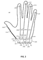
- FIG. 3 illustrates a plan view of a haptic glove 300 with an alternate tendon configuration, according to an embodiment.
- the embodiment of the haptic glove 300 illustrated in FIG. 3 has a different tendon configuration than the haptic glove 200 illustrated in FIG. 2 .
- the actuators 215 A- 215 E of the haptic glove 300 in FIG. 2 were directly coupled to the wristband 220
- the actuators 215 A- 215 E of the haptic glove 300 in FIG. 3 are each coupled to a respective second tendon 320 A- 320 E which couples to the wristband 220 at a respective coupling point 310 A- 310 E.
- the coupling points 310 A- 310 E may be rigid anchors to the wristband 220 .
- the actuators 215 A- 215 E may be directly coupled to the fabric of the haptic glove 300 .
- the actuators 215 A- 215 E may alternately be free-floating with respect to the fabric of the haptic glove 300 .
- Each actuator 215 A- 215 E may be controlled by the controller 270 to contract a respective first tendon 210 A- 210 E while the length of the respective second tendon 320 A- 320 E remains relatively invariant.
- each actuator 215 A- 215 E may contract the second tendon 320 A- 320 E to produce tension, while the length of the respective first tendon 210 A- 210 E remains relatively invariant.
- the actuators 215 A- 215 E may exert tension by contracting both the first tendons 210 A- 210 E and the second tendons 320 A- 320 E.
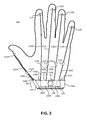
- FIG. 4 illustrates a plan view of a wristband 400 with wires 420 A- 420 D for tension adjustment, in accordance with an embodiment.
- the wristband 400 may be an embodiment of the wristband 220 illustrated in FIGS. 2-3 .
- the wristband 400 includes one or more adjustable strips (e.g., adjustable strips 250 A- 250 B), each of which includes one or more wires 420 A- 420 D over a thin strip 410 A- 410 B.
- the wristband 400 illustrated in FIG. 4 includes two adjustable strips 250 A- 250 B, each of which includes two wires 420 A- 420 D over a thin strip 410 A- 410 B.
- the wires 420 A- 420 D couple between the ratchet 230 and the force distribution segments 240 A- 240 B.
- any type of tendon may alternately be used, such as, strings, rods, chords, chains, or elastic structures.
- the wristband 400 includes a different number of wires than shown in FIG. 4 .
- the wristband 400 may also include a layer of material (e.g., fabric) over the wires 420 A- 420 D or sheaths that enclose the wires 420 A- 420 D.
- the thin strips 410 A- 410 B are layers of material beneath the wires 420 A- 420 D.
- the thin strips 410 A- 410 B may be composed of elastic material (e.g., neoprene), inelastic fabric, or some combination thereof. In some embodiments, the thin strips 410 A- 410 B are omitted entirely.
- the ratchet 430 is an embodiment of the ratchet 230 of FIGS. 2-3 .
- the ratchet 430 may comprise one or more reels about which the wires 420 A- 420 D are wound. The one or more reels retract the wires 420 A- 420 D into the ratchet 430 when rotated in a first direction and provide slack when rotated in the opposite direction.
- the ratchet 430 may include a locking mechanism so that in a locked position the one or more reels can rotate in the first direction to retract the wires 420 A- 420 D, but cannot rotate in the opposite direction to provide slack to the wires 420 A- 420 D. That is, the one or more reels are ratchetable.
- the ratchet 430 In an unlocked position, the one or more reels of the ratchet 430 may be free to rotate in either direction, thereby allowing the user to reduce the tension in the wristband 400 .
- the ratchet 430 comprises a knob configured to rotate the one or more reels. Lifting the knob up may set the ratchet 430 to the unlocked position and pressing the knob down may set it to the locked position (or vice versa).
- the knob and the one or more reels are rotationally coupled, but the knob and the one or more reels are disengaged in the unlocked position.
- the ratchet 430 is unlocked by disengaging a pawl from a gear rotationally coupled to the knob, the one or more reels, or both.
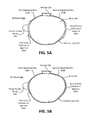
- FIG. 5A illustrates a cross-section of a wristband 500 with force distribution segments 240 A- 240 B that are each continuous elements, according to an embodiment.
- the wristband 500 may be part of a haptic glove (e.g., haptic glove 200 ).
- the wristband 500 includes two adjustable strips 250 A- 250 B, two force distribution segments 240 A- 240 B, a thumb tendon mount 260 , a ratchet 230 , and an anterior strip 510 .
- FIG. 5A shows a cross-section of a user's wrist 580 , that the wristband 500 encircles.
- the user's wrist 580 is illustrated as a dotted outline.
- Each the force distribution segments 240 A- 240 B may be a continuous, curved solid element.
- the force distribution segments 240 A- 240 B may be curved in the same direction as the surface of the wrist to which they are adjacent.
- the force distribution segments 240 A- 240 B may be a segment of an oblong annular cylinder.
- the force distribution segments 240 A- 240 B are flexible in the direction perpendicular to the surface of the wrist.
- a tension in the wristband 220 may cause the force distribution segments 240 A- 240 B to bend towards the curvature of the wrist.
- tension in the wristband 220 may cause the force distribution segments 240 A- 240 B to conform to the wrist's curvature.
- FIG. 5A also shows an anterior strip 510 , which couples between the first and second force distribution segments 240 A- 240 B.
- the anterior strip 510 may be an elastic strip (e.g., rubber) or an inelastic flexible strip (e.g., fabric).
- the anterior strip 510 comprises a thin elastic strip under one or more wires, wherein each wire couples between the force distribution segments 240 A- 240 B.
- any type of tendon may be used, such as, strings, rods, chords, chains, or elastic structures.
- the wires may bear most of the tension in the anterior strip 510 .
- elements of the anterior strip 510 are coupled to one or both of the adjustable strips 250 A- 250 B.
- the anterior strip 510 may comprise one or more wires (e.g., wires 420 A, 420 B) that are also part of the first adjustable strip 250 A. These one or more wires may run through or over the force distribution segment 240 A. In this way, when the ratchet 230 retracts these wires, the length of the first adjustable strip 250 A and the length of the anterior strip 510 may both be shortened.
- the anterior strip 510 may comprise one or more wires (e.g., 420 C, 420 D) that are also part of the second adjustable strip 250 B.
- one or more continuous wires may be part of the first and second adjustable strips 250 A, 250 B and the anterior strip 510 .
- wire 420 A of the first adjustable strip 250 A and the wire 420 C of the second adjustable strip 250 B may be portions of the same continuous wire.
- These one or more wires may encircle the wrist, running from one end of the ratchet 230 to the opposite end of the ratchet 230 .
- the anterior strip 510 is replaced by a tension adjustment mechanism similar to that on the posterior side of the wrist (e.g., two adjustable strips coupled to ratchet configured to adjust the length of the adjustable strips).
- the anterior strip 510 may include a ratchetable buckle strap system, a releasable pawl and gear rack system, a ladderlock strap system, or a fabric hook and fastener strap system.
- the anterior strip 510 A is omitted.
- the force distribution segments 240 A, 240 B may directly couple to each other with one or more hinges.
- the force distribution segments 240 A, 240 B may be constituent portions of a single continuous element.
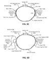
- FIG. 5B illustrates a cross-section of a wristband 520 including series of links, according to an embodiment.
- the wristband 520 may part of a haptic glove (e.g., haptic glove 200 ).
- the wristband may include force distribution segments 240 A- 240 B that each comprise a series of links.
- These links may be rigid elements (e.g., plastic, metal, or ceramic) connected to each other by hinges, which permit the links to rotate relative to each other.
- the hinges may be configured to allow rotation along an axis parallel to the surface of the user's wrist thereby allowing the force distribution segments 240 A, 240 B to conform to the curvature of the user's wrist.
- FIG. 5C illustrates a cross-section of a wristband 530 including meshes, according to some embodiments.
- the wristband 530 may be part of a haptic glove (e.g., haptic glove 200 ).
- the wristband 530 may include force distribution segments 240 A, 240 B.
- Force distribution segment 240 A includes a mesh 540 A over a thin elastic strop 540 A
- force distribution segment 240 B includes a mesh 540 B over a thin elastic strip 540 B.
- Each mesh 540 A, 540 B may consist of interconnected links, such as metal rings.
- the mesh 540 A, 540 B may be, for example, a Milanese mesh.
- the meshes 540 A, 540 B may be compliant in a direction perpendicular to the surface of the user's wrist 580 , but relatively stiff to forces parallel to the surface of the user's wrist 580 .
- FIG. 5C does not depict a thumb tendon mount 260 .
- the wristband 530 does not include a thumb tendon mount 260 , and a thumb tendon (e.g., tendon 215 A) couples to an alternate part of the wristband 530 (e.g., the mesh 540 A).
- the first force distribution segment 240 A includes a thumb tendon mount 260 which couples to the thumb tendon.
- FIG. 5D illustrates a cross-section of a wristband 550 including hinged segments, according to an embodiment.
- the wristband 550 may be part of a haptic glove (e.g., haptic glove 200 ) and may include force distribution segments 240 A- 240 B.
- the force distribution segment 240 A includes an upper segment 560 A, and a hinge 570 A connecting the upper segment 560 A to a lower segment 560 A.
- the force distribution segment 240 B includes an upper segment 560 B, and a hinge 570 B connecting the upper segment 560 B to a lower segment 560 B.
- Each of the hinges 570 A, 570 B allows their respective upper and lower segments 560 A, 560 D to rotate with respect to each other.
- each of the force distribution segments 240 A, 240 B include more than two segments (e.g., 560 A-D) and more than one hinge (e.g., hinges 570 A, 570 B) to connect them.
- the upper segments 560 A, 560 B and lower segments 560 C, 560 D are rigid bodies.
- the upper segments 560 A, 560 B and lower segments 560 C, 560 D are flexible in a direction perpendicular to the surface of the user's wrist 580 , but inflexible (i.e., not susceptible to bending) in directions parallel to the surface of the user's wrist 580 .
- a software module is implemented with a computer program product comprising a computer-readable medium containing computer program code, which can be executed by a computer processor for performing any or all of the steps, operations, or processes described.
- Embodiments of the disclosure may also relate to an apparatus for performing the operations herein.
- This apparatus may be specially constructed for the required purposes, and/or it may comprise a general-purpose computing device selectively activated or reconfigured by a computer program stored in the computer.
- a computer program may be stored in a non-transitory, tangible computer readable storage medium, or any type of media suitable for storing electronic instructions, which may be coupled to a computer system bus.
- any computing systems referred to in the specification may include a single processor or may be architectures employing multiple processor designs for increased computing capability.
- Embodiments of the disclosure may also relate to a product that is produced by a computing process described herein.
- a product may comprise information resulting from a computing process, where the information is stored on a non-transitory, tangible computer readable storage medium and may include any embodiment of a computer program product or other data combination described herein.
Landscapes
- Engineering & Computer Science (AREA)
- General Engineering & Computer Science (AREA)
- Theoretical Computer Science (AREA)
- Human Computer Interaction (AREA)
- Physics & Mathematics (AREA)
- General Physics & Mathematics (AREA)
- Textile Engineering (AREA)
- User Interface Of Digital Computer (AREA)
Abstract
Description
- The present disclosure generally relates to virtual reality systems, and specifically relates to a wristband for grounding forces generated by a haptic glove.
- Virtual reality (VR) systems typically provide multiple forms of sensory output, such as a head-mounted display and headphones, which operate together to create the illusion that a user is immersed in a virtual world. A VR system can also include an input device such as a haptic glove that can be used to detect the position, acceleration, orientation, or some combination thereof of the user's hand and uses the information as input. The input can then be used to move a corresponding item in the virtual world (e.g., a hand or other appendage belonging to a character in the virtual world) when the VR system detects movement of the haptic glove in the real world. A haptic glove can also be used to facilitate interactions with other objects in the virtual world. For example, the VR system can allow the user to use the haptic glove to manipulate virtual objects by touching them, picking them up, and moving them.
- Similarly, a haptic glove may be used in a mixed reality (MR) system. A MR system combines virtual elements with elements from physical world (e.g., a live video feed). For example, a MR system may be an augmented reality (AR) system. An example of an AR system is a display which overlays virtual objects on a live video feed. Virtual elements displayed in the AR may correspond to physical phenomena detected by the AR system (e.g., a virtual representation a magnetic field). The haptic glove may be used to interact with virtual objects or physical objects in an AR system.
- A force ground device glove is described. In some embodiments, the force ground device is part of a haptic glove. The force ground device includes one or more finger sheaths, one or more tendons, and one or more actuators. The one or more finger sheaths are configured to enclose a finger of a user of the force grounding device. The one or more tendons connect to respective finger sheaths, and each tendon may have a first end and a second end where the first end couples to the respective finger sheath. The one or more actuators are coupled to the second end of respective tendons, and are configured to produce tension in the respective tendons.
- The force ground device may also include a wristband coupled to the one or more actuators. The wrist band is configured to ground forces from the one or more actuators to a wrist of the user. The wristband may include one or more force distribution segments, one or more adjustable strips, one or more tension adjustment mechanism, or some combination thereof.
- In some embodiment, the wristband may include one or more force distribution segments that are inflexible in directions parallel to a surface of a wrist. The first force distribution band may distribute forces on the wristband from the one or more actuators to a side of the wrist. For example, a first force distribution segment may be adjacent to an ulna bone of the wrist and a second force distribution segment may be adjacent to a radius bone of the wrist.
- In some embodiments, the wristband may also include one or more adjustable strips. The adjustable strips may be coupled to the one or more force distribution segments. The one or more tension adjustment mechanisms may couple to the adjustable strips. Each tension adjustment mechanisms may be configured to adjust tension in and/or the length of adjustable strips to which it is coupled. For example, a tension adjustment mechanism adjacent to the posterior of the user's wrist may couple to two adjustable strips which each couple to a respective force distribution segment. In some embodiments, the wristband further comprises an anterior band, which may couple between two force distribution segments.
- The one or more adjustable strips may each include one or more wristband tendons. The wristband tendons may couple between one of the force distribution segments and one of the tension adjustment mechanisms. A tension adjustment mechanism may be configured to increase the tension in an adjustable strip by partially withdrawing the one or more tendons corresponding to the adjustable strip into itself. The tension adjustment mechanism allows a user to manually adjust the tension in the wristband by operating as a ratcheting mechanism.
- In some embodiments, each of the one or more force distribution segments may include a plurality of interconnected rigid links. In alternate embodiments, each of the one or more force distribution segments includes a mesh and an elastic strip. The elastic strip is positioned between the wrist and the mesh. The elastic strip may be composed of neoprene and the mesh may be a Milanese mesh. In some embodiments, the one or more force distribution segments are flexible in a first direction perpendicular to the surface of the wrist.
- The one or more finger sheaths may include a thumb sheath that encloses the thumb of a user. The thumb sheath may couples to thumb tendon, which, in turn, couples to a thumb tendon. A thumb tension adjustment mechanism on the wristband may be configured to allow a user to adjust the default tension in the thumb tendon.
-
FIG. 1 is a block diagram of a system environment, in accordance with an embodiment. -
FIG. 2 illustrates a plan view of a haptic glove, in accordance with an embodiment. -
FIG. 3 illustrates a plan view of a haptic glove with an alternate tendon configuration, in accordance with an embodiment. -
FIG. 4 illustrates a plan view of a wristband with wires for tension adjustment, in accordance with an embodiment. -
FIG. 5A illustrates a cross-section of a wristband with force distribution segments that are each continuous elements, according to an embodiment. -
FIG. 5B illustrates a cross-section of a wristband including series of links, according to an embodiment. -
FIG. 5C illustrates a cross-section of a wristband including meshes, according to an embodiment. -
FIG. 5D illustrates a cross-section of a wristband including hinged segments, according to an embodiment. - The figures depict embodiments of the present disclosure for purposes of illustration only. One skilled in the art will readily recognize from the following description that alternative embodiments of the structures and methods illustrated herein may be employed without departing from the principles, or benefits touted, of the disclosure described herein.
- To provide a more immersive experience in a VR, MR, or AR system, a haptic glove may apply force to a user's hand to simulate a user's interaction with a virtual object. For example, the system may detect that a user has reached out to grab a virtual object. This may be detected by sensors integrated into a haptic glove, sensors external to a haptic glove, or some combination thereof. As the user closes her hand to grasp the virtual object, the glove may generate an opposing force that resists the closing of the hand. In this way, the haptic glove simulates the experience of grasping the virtual object. The haptic glove may also produce force feedback corresponding to a real-world machine controlled by the user. For example, the forces generated by the haptic glove may correspond to forces and/or torques applied by a motor or system of motors in, for example, heavy machinery (e.g., an excavator), a robotic surgery system, a telerobotic system, or some combination thereof.
- The haptic glove may apply forces to the user's hand via one or more tendons adjacent to the back of the user's hand (i.e., the posterior side of the hand). A tendon may connect to an anchor point and to the posterior side of a user's finger. By modulating tension in this tendon by an actuator, the tendon may produce a force resisting the closing of the user's hand, thereby simulating the normal forces of a virtual object grasped by the user.
- Depending on how an anchor point is attached to the glove, forces on the anchor point may cause the haptic glove to deform, shift its position on the user's hand, or produce uncomfortable, irritating forces on the user's hand. For example, if the anchor is attached to compliant fabric on the haptic glove, a tension in the tendon may produce an undesirable deformation of the fabric around the anchor point.
- Deformation of the haptic glove is undesirable because, as tension in a tendon is repeatedly applied and released, the glove may repeatedly deform and shift along the surface of the user's hand. Friction produced by this repeated movement may irritate the user's hand. Furthermore, if tension in the tendon causes the anchor point's position on the user's hand to shift significantly, in order to produce sufficient tension, the tendon may need to be shortened further than it would if the anchor point's position was invariant. Accordingly, it is advantageous for an anchor point of a tendon system to, as close as practicable, remain fixed to the user's hand and/or wrist. That is, the anchor point should not move relative to the user's hand or deform the haptic glove when a force is applied. Such an anchor point is referred to herein as a “grounded” anchor.
- A haptic glove that grounds the forces from tensioned tendons to a wristband may resolve the aforementioned problems. The wristband distributes the forces from the tendons to the ulnar and radial sides of the wrist (i.e., the bony portions on the side of the wrist). The interface between the sides of the wrist and wristband may provide lateral stiffness so that wristband remains fixed to the wrist. Tension in the wristband produces compressive force between the wristband and the sides of the user's wrist. This compressive force increases the lateral stiffness between the sides of the user's wrist and the wristband of the haptic glove.
-
FIG. 1 is a block diagram of asystem environment 100 in which ahaptic interface garment 140 operates. Thesystem environment 100 may be, for example, a VR, MR, or AR system. In some embodiments, thesystem environment 100 is capable of alternating between operating as a VR, an MR, and an AR system, or some subset thereof. Thesystem environment 100 shown inFIG. 1 comprises a head-mounted display (HMD) 110 and ahaptic interface garment 140 that are both coupled to aconsole 170. WhileFIG. 1 shows anexample system environment 100 including oneHMD 110 and onehaptic interface garment 140, in other embodiments any number of these components may be included in thesystem environment 100. For example, thesystem environment 100 may include two haptic interface garments 140 (e.g., one haptic glove for each hand) that are worn by the same user. As another example, thesystem environment 100 may include multiplehaptic interface garments 140 intended to be worn by multiple users, with eachhaptic interface garment 140 or each pair ofhaptic interface garments 140 associated with adifferent HMD 110. In alternative configurations, different or additional components may be included in thesystem environment 100. - The
HMD 110 is a head-mounted display that presents media to a user. Examples of media presented by theHMD 110 include images, video, audio, or some combination thereof. In some embodiments, audio is presented via an external device (e.g., speakers or headphones) that receives audio information from theHMD 110, theconsole 170, or both, and presents audio data based on the audio information. In some embodiments, theHMD 110 may also act as an AR and/or MR headset. In these embodiments, theHMD 110 augments views of a physical, real-world environment with computer-generated elements (e.g., images, video, sound, etc.). - The
HMD 110 includes anelectronic display 112,sensors 114, and acommunication interface 116. Some embodiments of theHMD 110 have different components than those described here. Similarly, the functions can be distributed among the components in a different manner than is described here. - The
electronic display 112 displays images to the user in accordance with data received from theconsole 170. In various embodiments, theelectronic display 112 may comprise a singleelectronic display 112 or multiple electronic displays 112 (e.g., one display for each eye of a user). - The
sensors 114 include one or more hardware devices that detect spatial and motion information about theHMD 110. Spatial and motion information can include information about the position, orientation, velocity, rotation, and acceleration of theHMD 110. For example, thesensors 114 may include a gyroscope that detects rotation of the user's head while the user is wearing theHMD 110. This rotation information can then be used (e.g., by the engine 174) to adjust the images displayed on theelectronic display 112. - The
communication interface 116 enables input and output to theconsole 170. In some embodiments, thecommunication interface 116 is a bus, such as High-Definition Multimedia Interface (HDMI), Universal Serial Bus (USB), Video Graphics Array (VGA), Digital Visual Interface (DVI), DisplayPort™, or some combination thereof. In other embodiments, thecommunication interface 116 includes several distinct communication buses operating together or independently. In one embodiment, thecommunication interface 116 includes wireless connections for sending data collected by thesensors 114 from theHMD 110 to theconsole 170 but also includes a wired connection (e.g., an HDMI or DVI connection) that receives audio/visual data to be rendered on theelectronic display 112. - The
haptic interface garment 140 is a wearable device for receiving haptic input or producing haptic output. Thehaptic interface garment 140 may be configured to be worn on a portion of a user's body, such as the user's hand (e.g., a glove). Thehaptic interface garment 140 may collect information about the portion of the user's body that can be used as input forvirtual reality applications 172 executing on theconsole 170. Thehaptic interface garment 140 includes a haptic feedback mechanism 142,sensors 144, and acommunication interface 146. Some embodiments of thehaptic interface garment 140 have different components than those described here, e.g., thehaptic interface garment 140 may include additional components that are not shown inFIG. 1 , such as a power source (e.g., an integrated battery, a connection to an external power source, a container containing compressed air, or some combination thereof). Similarly, the functions can be distributed among the components in a different manner than is described here. - The haptic feedback mechanism 142 provides haptic feedback to the user by directing the portion of the user's body to move in a particular way or in a particular direction or preventing the portion of the user's body from moving in certain directions or in certain ways. The haptic feedback mechanism 142 includes a tendon system to apply force to the
haptic interface garment 140. Transducers of the tendon system may apply forces on portions of the user's body. By applying forces to the user's body, the tendon system may move a portion of the user's body apply torque to a joint of a user's body, or produce tactile sensation for the user. Various embodiments of the haptic feedback mechanism 142 are described in conjunction withFIGS. 2-5D . - The
sensors 144 include one or more hardware devices that detect spatial information for thehaptic interface garment 140. The spatial information may include information about position, orientation, velocity, rotation, and acceleration, or some combination thereof. The spatial information may refer to the entirehaptic interface garment 140, subdivisions of thehaptic interface garment 140, or both. For example, if thehaptic interface garment 140 is a haptic glove,sensors 144 may identify positions and orientations of various portions of the glove, such as the fingers, fingertips, knuckles, palm, or wrist. Thesensors 144 may also detect forces applied by the user to thehaptic interface garment 140. - The
communication interface 146 enables input from and output to theconsole 170. In some embodiments, thecommunication interface 146 may be a single communication bus, such as USB. In other embodiments, thecommunication interface 146 includes several distinct communication buses operating together or independently. For example, thecommunication interface 146 may include separate communication buses for receiving control signals for the haptic feedback mechanism 142 and sending data from thesensors 144 to theconsole 170. The one or more communication buses of thecommunication interface 146 may be implemented as wired connections, wireless connections, or some combination thereof. - The
console 170 is a computing device that executes virtual reality applications, augmented reality applications, mixed reality applications, or some combination thereof, to process input data from thesensors HMD 110 and thehaptic interface garment 140 and provide output data for theelectronic display 112 on theHMD 110 and the haptic feedback mechanism 142 on thehaptic interface garment 140. Theconsole 170, or portions thereof, may be integrated with theHMD 110, thehaptic interface garment 140, or both theHMD 110 and thehaptic interface garment 140. Theconsole 170 can be implemented as any kind of computing device, such as an integrated system-on-a-chip, a microcontroller, a desktop or laptop computer, a server computer, a tablet, a smart phone, or other mobile device. Thus, theconsole 170 may include components common to typical computing devices, such as a processor, random access memory (RAM), a storage device, a network interface, an I/O interface, and the like. - The processor may be or include one or more graphics processing units (GPUs), microprocessors, or application specific integrated circuits (ASICs). The memory may be or include RAM, ROM, DRAM, SRAM, and MRAM, and may include firmware, such as static data or fixed instructions, BIOS, system functions, configuration data, and other routines used during the operation of the computing device and the processor. The memory also provides a storage area for data and instructions associated with applications and data handled by the processor.
- The storage device provides non-volatile, bulk, or long term storage of data or instructions in the computing device. The storage device may take the form of a magnetic or solid state disk, tape, CD, DVD, or other reasonably high capacity addressable or serial storage medium. Multiple storage devices may be provided or be available to the computing device. Some of these storage devices may be external to the computing device, such as network storage or cloud-based storage. The network interface includes an interface to a network and can be implemented as either a wired or wireless interface. The I/O interface interfaces the processor to peripherals (not shown) such as, depending upon the computing device, sensors, displays, cameras, color sensors, microphones, keyboards and USB devices.
- In the example shown in
FIG. 1 , theconsole 170 further includesapplications 172 and anengine 174. Anapplication 172 running on theengine 174 may generate a VR environment, an AR environment, an MR environment, or some combination thereof. In some embodiments, theapplications 172 and theengine 174 are implemented as software modules that are stored on the storage device and executed by the processor. Some embodiments of theconsole 170 include additional or different components than those described in conjunction withFIG. 1 . Similarly, the functions further described below may be distributed among components of theconsole 170 in a different manner than is described here. - Each
application 172 is a group of instructions that, when executed by a processor, generates virtual reality content for presentation to the user. Anapplication 172 may generate content (e.g., VR, MR, or AR content) in response to inputs received from the user via movement of theHMD 110 or thehaptic interface garment 140. Examples ofapplications 172 include gaming applications, conferencing applications, video playback applications, augmented reality application, telerobotic applications, or other suitable applications. - The
engine 174 is a software module that allows theapplications 172 to operate in conjunction with theHMD 110 and thehaptic interface garment 140. In some embodiments, theengine 174 receives information fromsensors 114 on theHMD 110 and provides the information to anapplication 172. Based on the received information, theengine 174 determines media content to provide to theHMD 110 for presentation to the user via theelectronic display 112 or haptic feedback to provide to thehaptic interface garment 140 to provide to the user via the haptic feedback mechanism. For example, if theengine 174 receives information from thesensors 114 on theHMD 110 indicating that the user has looked to the left, theengine 174 generates content for theHMD 110 that mirrors the user's movement in a virtual environment. - Similarly, in some embodiments the
engine 174 receives information from thesensors 144 on thehaptic interface garment 140 and provides the information to anapplication 172. Theapplication 172 can use the information to perform an action within the virtual world of theapplication 172. For example, if theengine 174 receives information from thesensors 144 that the user has closed her fingers around a position corresponding to a coffee mug in the virtual environment and raised her hand, a simulated hand in theapplication 172 picks up the virtual coffee mug and lifts it to a corresponding height. - The
engine 174 may also provide feedback to the user that the action was performed. The provided feedback may be visual via theelectronic display 112 in the HMD 110 (e.g., displaying the simulated hand as it picks up and lifts the virtual coffee mug) or haptic feedback via the haptic feedback mechanism 142 in the haptic interface garment 140 (e.g., resisting movement of a user's fingers from curling past a certain point to simulate the sensation of touching a solid coffee mug). The haptic feedback may also be force feedback from some machine being controlled by the user. -
FIG. 2 illustrates a plan view of ahaptic glove 200, in accordance with an embodiment. Thehaptic glove 200 includes one ormore tendons 210A-210E, one ormore actuators 215A-215E, one or more finger-tendon anchors 212A-212E, acontroller 270, and awristband 220. In the embodiment ofFIG. 2 , each of the five finger sheaths of theglove 200 corresponds to arespective tendon 210A-210E, arespective actuator 215A-215E, and a respective finger-tendon anchor 212A-212E. InFIG. 2 , thehaptic glove 200 is shown in an orientation corresponding to posterior view of a user's right hand (i.e., a plan view of the back of the user's hand). - The
tendons 210A-210E are thin elements that each translate force from arespective actuator 215A-215E to a respective finger. For example, atendon 210A-210E may be a wire, string, rod, chord, chain, wire cable, or elastic structure. As depicted inFIG. 2 , each of thenon-thumb tendons 210B-210E runs along the back of the haptic glove 200 (i.e., the side of thehaptic glove 200 corresponding to the posterior side of the user's hand) and along the posterior side of its respective finger sheath. Thetendon 210A corresponding to the thumb may runs along the side of the thumb. - The
actuators 215A-215E are motors that each tension arespective tendon 210A-210-210E. Eachactuators 215A-215E may include an electromagnetic mechanism (e.g., one or more solenoids), a hydraulic mechanism, a pneumatic mechanism, a piezoelectric mechanism, or a combination thereof. When an electrical signal is delivered to anactuator 215A-215E, theactuator 215A-215E may apply a force to itsrespective tendon 210A-210E causing thetendon 210A-210E to be tensioned. By modulating the tension in thetendons 210A-210E via theactuators 215A-215E, thehaptic glove 200 can apply a force to the fingers of the user's hand. In this way, thehaptic glove 200 resists flexion of one or more of the user's fingers or causes extension of the fingers. Resistance to flexion from thehaptic glove 200 may be used in conjunction with the display of a virtual object in theHMD 110 to simulate the grasping of the virtual object. - Each of the finger-tendon anchors 212A-212E is a coupling between a
respective tendon 210A-210E and a respective finger sheath of thehaptic glove 200. In some embodiments, the finger-tendon anchors 212A-212E are located on different portions of the finger sheaths that is depicted inFIG. 2 . For example, some or all of the finger-tendon anchors 212A-212E could be adjacent to the distal interphalangeal joints of the fingers, the proximal interphalangeal joints, or both. In some embodiments, more than one finger-tendon anchor 212A-212E couples between eachtendon 210A-210E and the respective finger sheath. In addition, alternate embodiments use different types of finger-tendon anchors 212A-212E than those illustrated inFIG. 2 . - Each
tendon 210A-210E mechanically couples at a respective first end to a respective finger sheath via a respective finger-tendon anchor 212A-212E. Thefirst tendon 210A couples at the first end to the finger sheath corresponding to the user's thumb (i.e., the “thumb sheath”). The other fourtendons 210B-210E (i.e., the “finger tendons”) couple at respective first ends to finger sheaths corresponding to the user's index, middle, ring, and “pinky” fingers, respectively. Eachtendon 210A-210E mechanically couples at a respective second end to arespective actuator 215A-215E. The fiveactuators 215A-215E each couple to thewristband 220. Theactuators 215A-215E may be rigidly anchored to thewristband 220. Thefirst actuator 215A couples to thethumb tendon mount 260. Thesecond actuator 215B couples to the firstforce distribution segment 240A. Thethird actuator 215C couples to the firstadjustable strip 250A and the fourth andfifth actuators 215D-215E couple to the secondadjustable strip 215E. One or more of theactuators 215A-215E may couple to a respective tension adjustment mechanism, and in some embodiments all of theactuators 215A-215E may couple to a respective tension adjustment mechanism. These tension adjustment mechanisms may allow the user to configure the tension on eachtendon 210A-210E by adjusting its length to accommodate the shape of the user's hand (e.g., the length of the user's fingers). - In an alternate embodiment, the
actuators 215B-215E not corresponding to the thumb all couple at the same part of thewristband 220. For example, the fourfinger actuators 215B-215E may couple to the first or secondadjustable strip 250A, the first or secondforce distribution segments 240A-240B, or theratchet 230. In another embodiment, the twoactuators 215B-215C corresponding to the index and middle fingers couple to the firstadjustable strip 250A and the twoactuators 215D-215E corresponding to the ring and pinky fingers couple the secondadjustable strip 250B. In some embodiments, one or more of thefinger actuators 215B-215E are omitted and one or more of the finger tendons 210B-210E are coupled to the same actuator. For example, the fourfinger tendons 210B-210E may be coupled to a single actuator. Other coupling configurations for theactuators 215A-215E andtendons 210A-210E are also possible. - The
controller 270 is an electronic device the controls each of theactuators 215A-215E. Thecontroller 270 may receive input theconsole 170 that may determine setpoint position for each actuator, a force to apply to each actuator, or some combination thereof. Thecontroller 270 may include a digital-to-analog converter for converting input from theconsole 170 to an electrical signal for controlling theactuators 215A-215E. Thecontroller 270 may control theactuators 215A-215E individually or control a set of theactuators 215A-215E as a unit. A unit of actuators (e.g., every other actuator, all the actuators, or any other combination of actuators) may be controlled together, so that each actuator in the unit is tensioned or de-tensioned together. In some embodiments, thecontroller 270 is located at a different location on thehaptic glove 200. In alternate embodiments, the functions of thecontroller 270, as described herein, are implemented by a device external to but communicatively coupled to the haptic glove 200 (e.g., the console 170). - The
wristband 220 is a band that may encircle a user's wrist. Thewristband 220 may ground forces generated by theactuators 215A-215E. Thewristband 220 may ground these forces by distributing the forces from theactuators 215A-215E to the ulnar and radial sides of the wrist (i.e., the bony portions on the side of the wrist). Thewristband 220 includes aratchet 230, one or moreforce distribution segments 240A-240B, one or moreadjustable strips 250A-250B, and athumb tendon mount 260. In the embodiments shown inFIG. 2 , the wristband includes twoadjustable strips 250A-250B and twoforce distribution segments 240A-240B. - The
ratchet 230 is a tension adjustment mechanism with which a user can manually adjust the tension in thewristband 220. Theratchet 230 of thewristband 220 couples at a first end to a firstadjustable strip 250A and couples to a secondadjustable strip 250B at a second opposite end. Theratchet 230 may include a rotatable knob for adjusting tension. Theratchet 230 may include a locking mechanism so that in a locked position the knob can rotate in a first direction to tension the wristband, but cannot be rotated in the opposite direction to provide slack to the wristband. In an unlocked position, theratchet 230 releases tension in the wristband. Lifting the knob up may set theratchet 230 to the unlocked position and pressing the knob down may set it to the locked position (or vice versa). - The
adjustable strips 250A-250B are strips that couple to theratchet 230. Theadjustable strips 250A-250B may be adjusted in length by theratchet 230 to produce tension in thewristband 220. The first and secondadjustable strips force distribution segments 240A-240B, respectively. In alternate embodiments, theratchet 230 andadjustable strips 250A-250B are omitted in favor of an alternate tension adjustment mechanism, a linear ratchet mechanism (e.g., a ratchet strap), such as a ratchetable buckle strap system, a releasable pawl and gear rack system, a threaded buckle, a ladderlock strap system, or a fabric hook and fastener strap system. - The first and second
force distribution segments 240A-240B are components of thewristband 220 that may ground forces to the bony portions of the user's wrist. The first and secondforce distribution segments 240A-240B adjacent to the radial side and ulnar side, respectively, of the user's wrist. The firstforce distribution segment 240A is adjacent to the radial side (i.e., the “thumb side”) of the user's wrist, and the secondforce distribution segment 240B is adjacent to the ulnar side (i.e., the “pinky side”) of the wrist. Theforce distribution segments 240A-240B may rigidly couple to the wrist of the user. Tension in thewristband 220 is distributed along the sides of the wrist to ground the forces caused bytendons 210A-210E anchored to thewristband 220. Theforce distribution segments 240A-240B may be inflexible in directions parallel to the surface of the wrist. That is, forces parallel to the wrist's surface produce relatively little deformation of theforce distribution segments 240A-240B. The first and secondforce distribution segments 240A-240B may be coupled together. An anterior band (not shown) couples between the first and secondforce distribution segments 240A-240B in some embodiments. In alternate embodiments, the first and secondforce distribution segments 240A-240B may be portions of a single continuous element. Thewristband 220 also includes athumb tendon mount 260 that couples to the firstforce distribution segment 240A. - The
force distribution segments 240A-240B may be curved in the same direction as the surface of the wrist to which they are adjacent. In some embodiments, theforce distribution segments 240A-240B are flexible (e.g., susceptible to bending) in the direction perpendicular to the surface of the wrist. Thus, a tension in thewristband 220 may cause theforce distribution segments 240A-240B to bend towards the curvature of the wrist. As a result, tension in thewristband 220 causes theforce distribution segments 240A-240B to conform to the curvature of the wrist. By conforming to the sides of the wrist, thewristband 220 may distribute the force fromtendons 210A-210E over a larger area. Thus, theforce distribution segments 240A-240B allow thewristband 220 to effectively ground the forces produced by thetendons 210A-210E andactuators 215A-215E. Several embodiments offorce distribution segments 240A-240B are discussed below in conjunction withFIGS. 5A-5B . - The
thumb tendon mount 260 is a rigid component that is coupled to theactuator 215A corresponding to the thumb. Because thethumb tendon 210A runs along the side of the thumb, thethumb tendon mount 260 may extend from the side of the firstforce distribution segment 240A. Theactuator 215A, thethumb tendon mount 260, and the firstforce distribution segment 240A may be rigidly coupled together. Thethumb tendon mount 260 may be a continuous piece of the firstforce distribution segment 240A and may protrude therefrom. Theactuator 215A may be coupled to thethumb tendon mount 260 or may be integrated within thethumb tendon mount 260. Thethumb tendon mount 260 may include a tension adjustment mechanism for adjusting the default tension in thethumb tendon 210A. By adjusting the thumb tension mount, the user can adjust the length of thetendon 210A to accommodate the length of his or her thumb. - The
haptic glove 200 may be a full-fingered glove wearable on the user's hand. Thehaptic glove 200 may cover the user's hand with a textile, but it may also include other materials such as rubber, processed animal hide (e.g., leather), cloth, wool, a polymer (e.g., nylon, polyester, or latex), or some combination thereof. Thehaptic glove 200 may include multiple layers. For example, thetendons 210A-210E and theactuators 215A-215E may be enclosed between two layers of thehaptic glove 200. Thehaptic glove 200 may include five finger sheaths, each of which may entirely cover a respective finger or cover a portion of the finger (e.g., as in a fingerless glove). Thehaptic glove 200 may alternately be a mitten, or a gauntlet. -
FIG. 3 illustrates a plan view of ahaptic glove 300 with an alternate tendon configuration, according to an embodiment. The embodiment of thehaptic glove 300 illustrated inFIG. 3 has a different tendon configuration than thehaptic glove 200 illustrated inFIG. 2 . Whereas, theactuators 215A-215E of thehaptic glove 300 inFIG. 2 were directly coupled to thewristband 220, theactuators 215A-215E of thehaptic glove 300 inFIG. 3 are each coupled to a respectivesecond tendon 320A-320E which couples to thewristband 220 at arespective coupling point 310A-310E. The coupling points 310A-310E may be rigid anchors to thewristband 220. Theactuators 215A-215E may be directly coupled to the fabric of thehaptic glove 300. Theactuators 215A-215E may alternately be free-floating with respect to the fabric of thehaptic glove 300. - Each
actuator 215A-215E may be controlled by thecontroller 270 to contract a respectivefirst tendon 210A-210E while the length of the respectivesecond tendon 320A-320E remains relatively invariant. In an alternate embodiment, each actuator 215A-215E may contract thesecond tendon 320A-320E to produce tension, while the length of the respectivefirst tendon 210A-210E remains relatively invariant. In a third alternate embodiment, theactuators 215A-215E may exert tension by contracting both thefirst tendons 210A-210E and thesecond tendons 320A-320E. -
FIG. 4 illustrates a plan view of awristband 400 withwires 420A-420D for tension adjustment, in accordance with an embodiment. Thewristband 400 may be an embodiment of thewristband 220 illustrated inFIGS. 2-3 . Thewristband 400 includes one or more adjustable strips (e.g.,adjustable strips 250A-250B), each of which includes one ormore wires 420A-420D over athin strip 410A-410B. For example, thewristband 400 illustrated inFIG. 4 includes twoadjustable strips 250A-250B, each of which includes twowires 420A-420D over athin strip 410A-410B. - The
wires 420A-420D couple between theratchet 230 and theforce distribution segments 240A-240B. Instead ofwires 420A-420D, any type of tendon may alternately be used, such as, strings, rods, chords, chains, or elastic structures. In alternate embodiments, thewristband 400 includes a different number of wires than shown inFIG. 4 . Thewristband 400 may also include a layer of material (e.g., fabric) over thewires 420A-420D or sheaths that enclose thewires 420A-420D. - The thin strips 410A-410B are layers of material beneath the
wires 420A-420D. The thin strips 410A-410B may be composed of elastic material (e.g., neoprene), inelastic fabric, or some combination thereof. In some embodiments, thethin strips 410A-410B are omitted entirely. - The
ratchet 430 is an embodiment of theratchet 230 ofFIGS. 2-3 . Theratchet 430 may comprise one or more reels about which thewires 420A-420D are wound. The one or more reels retract thewires 420A-420D into theratchet 430 when rotated in a first direction and provide slack when rotated in the opposite direction. Theratchet 430 may include a locking mechanism so that in a locked position the one or more reels can rotate in the first direction to retract thewires 420A-420D, but cannot rotate in the opposite direction to provide slack to thewires 420A-420D. That is, the one or more reels are ratchetable. In an unlocked position, the one or more reels of theratchet 430 may be free to rotate in either direction, thereby allowing the user to reduce the tension in thewristband 400. In some embodiments, theratchet 430 comprises a knob configured to rotate the one or more reels. Lifting the knob up may set theratchet 430 to the unlocked position and pressing the knob down may set it to the locked position (or vice versa). In some embodiments, when theratchet 430 is in a locked position the knob and the one or more reels are rotationally coupled, but the knob and the one or more reels are disengaged in the unlocked position. In some embodiments, theratchet 430 is unlocked by disengaging a pawl from a gear rotationally coupled to the knob, the one or more reels, or both. -
FIG. 5A illustrates a cross-section of awristband 500 withforce distribution segments 240A-240B that are each continuous elements, according to an embodiment. Thewristband 500 may be part of a haptic glove (e.g., haptic glove 200). Thewristband 500 includes twoadjustable strips 250A-250B, twoforce distribution segments 240A-240B, athumb tendon mount 260, aratchet 230, and ananterior strip 510. For contextFIG. 5A shows a cross-section of a user'swrist 580, that thewristband 500 encircles. The user'swrist 580 is illustrated as a dotted outline. - Each the
force distribution segments 240A-240B may be a continuous, curved solid element. Theforce distribution segments 240A-240B may be curved in the same direction as the surface of the wrist to which they are adjacent. Theforce distribution segments 240A-240B may be a segment of an oblong annular cylinder. In some embodiments, theforce distribution segments 240A-240B are flexible in the direction perpendicular to the surface of the wrist. Thus, a tension in thewristband 220 may cause theforce distribution segments 240A-240B to bend towards the curvature of the wrist. As a result, tension in thewristband 220 may cause theforce distribution segments 240A-240B to conform to the wrist's curvature. -
FIG. 5A also shows ananterior strip 510, which couples between the first and secondforce distribution segments 240A-240B. Theanterior strip 510 may be an elastic strip (e.g., rubber) or an inelastic flexible strip (e.g., fabric). In some embodiments, theanterior strip 510 comprises a thin elastic strip under one or more wires, wherein each wire couples between theforce distribution segments 240A-240B. Instead of wires, any type of tendon may be used, such as, strings, rods, chords, chains, or elastic structures. The wires may bear most of the tension in theanterior strip 510. - In some embodiments, elements of the
anterior strip 510 are coupled to one or both of theadjustable strips 250A-250B. For example, theanterior strip 510 may comprise one or more wires (e.g.,wires adjustable strip 250A. These one or more wires may run through or over theforce distribution segment 240A. In this way, when theratchet 230 retracts these wires, the length of the firstadjustable strip 250A and the length of theanterior strip 510 may both be shortened. Similarly, theanterior strip 510 may comprise one or more wires (e.g., 420C, 420D) that are also part of the secondadjustable strip 250B. In this way, one or more continuous wires may be part of the first and secondadjustable strips anterior strip 510. For example,wire 420A of the firstadjustable strip 250A and thewire 420C of the secondadjustable strip 250B may be portions of the same continuous wire. These one or more wires may encircle the wrist, running from one end of theratchet 230 to the opposite end of theratchet 230. In alternate embodiments, theanterior strip 510 is replaced by a tension adjustment mechanism similar to that on the posterior side of the wrist (e.g., two adjustable strips coupled to ratchet configured to adjust the length of the adjustable strips). Alternately, theanterior strip 510 may include a ratchetable buckle strap system, a releasable pawl and gear rack system, a ladderlock strap system, or a fabric hook and fastener strap system. In some embodiments, the anterior strip 510A is omitted. In such embodiments, theforce distribution segments force distribution segments -
FIG. 5B illustrates a cross-section of awristband 520 including series of links, according to an embodiment. Thewristband 520 may part of a haptic glove (e.g., haptic glove 200). The wristband may includeforce distribution segments 240A-240B that each comprise a series of links. These links may be rigid elements (e.g., plastic, metal, or ceramic) connected to each other by hinges, which permit the links to rotate relative to each other. The hinges may be configured to allow rotation along an axis parallel to the surface of the user's wrist thereby allowing theforce distribution segments -
FIG. 5C illustrates a cross-section of awristband 530 including meshes, according to some embodiments. Thewristband 530 may be part of a haptic glove (e.g., haptic glove 200). Thewristband 530 may includeforce distribution segments Force distribution segment 240A includes amesh 540A over a thinelastic strop 540A, and forcedistribution segment 240B includes a mesh 540B over a thin elastic strip 540B. Eachmesh 540A, 540B may consist of interconnected links, such as metal rings. Themesh 540A, 540B may be, for example, a Milanese mesh. Themeshes 540A,540B may be compliant in a direction perpendicular to the surface of the user'swrist 580, but relatively stiff to forces parallel to the surface of the user'swrist 580. -
FIG. 5C does not depict athumb tendon mount 260. In some embodiments, thewristband 530 does not include athumb tendon mount 260, and a thumb tendon (e.g.,tendon 215A) couples to an alternate part of the wristband 530 (e.g., themesh 540A). In alternate embodiments, the firstforce distribution segment 240A includes athumb tendon mount 260 which couples to the thumb tendon. -
FIG. 5D illustrates a cross-section of awristband 550 including hinged segments, according to an embodiment. Thewristband 550 may be part of a haptic glove (e.g., haptic glove 200) and may includeforce distribution segments 240A-240B. Theforce distribution segment 240A includes anupper segment 560A, and ahinge 570A connecting theupper segment 560A to alower segment 560A. Theforce distribution segment 240B includes anupper segment 560B, and ahinge 570B connecting theupper segment 560B to alower segment 560B. Each of thehinges lower segments hinges force distribution segments upper segments lower segments upper segments lower segments wrist 580, but inflexible (i.e., not susceptible to bending) in directions parallel to the surface of the user'swrist 580. - The foregoing description of the embodiments of the disclosure have been presented for the purpose of illustration; it is not intended to be exhaustive or to limit the disclosure to the precise forms disclosed. Persons skilled in the relevant art can appreciate that many modifications and variations are possible in light of the above disclosure.
- Some portions of this description describe the embodiments of the disclosure in terms of algorithms and symbolic representations of operations on information. These algorithmic descriptions and representations are commonly used by those skilled in the data processing arts to convey the substance of their work effectively to others skilled in the art. These operations, while described functionally, computationally, or logically, are understood to be implemented by computer programs or equivalent electrical circuits, microcode, or the like. Furthermore, it has also proven convenient at times, to refer to these arrangements of operations as modules, without loss of generality. The described operations and their associated modules may be embodied in software, firmware, hardware, or any combinations thereof.
- Any of the steps, operations, or processes described herein may be performed or implemented with one or more hardware or software modules, alone or in combination with other devices. In one embodiment, a software module is implemented with a computer program product comprising a computer-readable medium containing computer program code, which can be executed by a computer processor for performing any or all of the steps, operations, or processes described.
- Embodiments of the disclosure may also relate to an apparatus for performing the operations herein. This apparatus may be specially constructed for the required purposes, and/or it may comprise a general-purpose computing device selectively activated or reconfigured by a computer program stored in the computer. Such a computer program may be stored in a non-transitory, tangible computer readable storage medium, or any type of media suitable for storing electronic instructions, which may be coupled to a computer system bus. Furthermore, any computing systems referred to in the specification may include a single processor or may be architectures employing multiple processor designs for increased computing capability.
- Embodiments of the disclosure may also relate to a product that is produced by a computing process described herein. Such a product may comprise information resulting from a computing process, where the information is stored on a non-transitory, tangible computer readable storage medium and may include any embodiment of a computer program product or other data combination described herein.
- Finally, the language used in the specification has been principally selected for readability and instructional purposes, and it may not have been selected to delineate or circumscribe the inventive subject matter. It is therefore intended that the scope of the disclosure be limited not by this detailed description, but rather by any claims that issue on an application based hereon. Accordingly, the disclosure of the embodiments is intended to be illustrative, but not limiting, of the scope of the disclosure, which is set forth in the following claims.
Claims (13)
Priority Applications (1)
| Application Number | Priority Date | Filing Date | Title |
|---|---|---|---|
| US15/291,944 US20180098583A1 (en) | 2016-10-12 | 2016-10-12 | Force grounding wristband for haptic glove |
Applications Claiming Priority (1)
| Application Number | Priority Date | Filing Date | Title |
|---|---|---|---|
| US15/291,944 US20180098583A1 (en) | 2016-10-12 | 2016-10-12 | Force grounding wristband for haptic glove |
Publications (1)
| Publication Number | Publication Date |
|---|---|
| US20180098583A1 true US20180098583A1 (en) | 2018-04-12 |
Family
ID=61829454
Family Applications (1)
| Application Number | Title | Priority Date | Filing Date |
|---|---|---|---|
| US15/291,944 Abandoned US20180098583A1 (en) | 2016-10-12 | 2016-10-12 | Force grounding wristband for haptic glove |
Country Status (1)
| Country | Link |
|---|---|
| US (1) | US20180098583A1 (en) |
Cited By (25)
| Publication number | Priority date | Publication date | Assignee | Title |
|---|---|---|---|---|
| US20190278372A1 (en) * | 2016-12-15 | 2019-09-12 | Sony Interactive Entertainment Inc. | Information processing system, controller device, controller device control method and program |
| US20200081532A1 (en) * | 2018-09-06 | 2020-03-12 | Microsoft Technology Licensing, Llc | Selective restriction of skeletal joint motion |
| US10613626B2 (en) * | 2018-06-15 | 2020-04-07 | Immersion Corporation | Kinesthetically enabled glove |
| US10671163B2 (en) * | 2018-07-24 | 2020-06-02 | Microsoft Technology Licensing, Llc | Refining virtual mesh models through physical contacts |
| US10779583B2 (en) * | 2016-09-20 | 2020-09-22 | Facebook Technologies, Llc | Actuated tendon pairs in a virtual reality device |
| US10860102B2 (en) | 2019-05-08 | 2020-12-08 | Microsoft Technology Licensing, Llc | Guide for supporting flexible articulating structure |
| US10963054B2 (en) | 2016-12-15 | 2021-03-30 | Sony Interactive Entertainment Inc. | Information processing system, vibration control method and program |
| US10963055B2 (en) | 2016-12-15 | 2021-03-30 | Sony Interactive Entertainment Inc. | Vibration device and control system for presenting corrected vibration data |
| US10981053B2 (en) | 2017-04-18 | 2021-04-20 | Sony Interactive Entertainment Inc. | Vibration control apparatus |
| US11016598B1 (en) * | 2017-11-30 | 2021-05-25 | Southeast University | Artificial finger tip sliding touch sensor |
| US11013990B2 (en) | 2017-04-19 | 2021-05-25 | Sony Interactive Entertainment Inc. | Vibration control apparatus |
| US11023047B2 (en) | 2018-05-01 | 2021-06-01 | Microsoft Technology Licensing, Llc | Electrostatic slide clutch with bidirectional drive circuit |
| US11036295B2 (en) | 2016-11-23 | 2021-06-15 | Microsoft Technology Licensing, Llc | Electrostatic slide clutch |
| US11054905B2 (en) | 2019-05-24 | 2021-07-06 | Microsoft Technology Licensing, Llc | Motion-restricting apparatus with common base electrode |
| US11061476B2 (en) | 2019-05-24 | 2021-07-13 | Microsoft Technology Licensing, Llc | Haptic feedback apparatus |
| US11062573B2 (en) * | 2019-01-31 | 2021-07-13 | Facebook Technologies, Llc | Using a fluidic mechanism on a wearable device for both haptic feedback and user input |
| US11145172B2 (en) | 2017-04-18 | 2021-10-12 | Sony Interactive Entertainment Inc. | Vibration control apparatus |
| US11157131B2 (en) * | 2017-02-24 | 2021-10-26 | Vrad Inc. | Virtual reality-based radiology practice apparatus and method |
| US11198059B2 (en) | 2017-08-29 | 2021-12-14 | Sony Interactive Entertainment Inc. | Vibration control apparatus, vibration control method, and program |
| US11458389B2 (en) | 2017-04-26 | 2022-10-04 | Sony Interactive Entertainment Inc. | Vibration control apparatus |
| US11579692B2 (en) | 2013-07-05 | 2023-02-14 | Haptx, Inc. | Whole-body human-computer interface |
| EP3979966A4 (en) * | 2019-06-07 | 2023-07-05 | Osind Medi Tech Private Limited | A self driven rehabilitation device and method thereof |
| US11738261B2 (en) | 2017-08-24 | 2023-08-29 | Sony Interactive Entertainment Inc. | Vibration control apparatus |
| US11779836B2 (en) | 2017-08-24 | 2023-10-10 | Sony Interactive Entertainment Inc. | Vibration control apparatus |
| US11816268B2 (en) | 2020-10-22 | 2023-11-14 | Haptx, Inc. | Actuator and retraction mechanism for force feedback exoskeleton |
Citations (5)
| Publication number | Priority date | Publication date | Assignee | Title |
|---|---|---|---|---|
| US20010043847A1 (en) * | 1990-02-02 | 2001-11-22 | James Kramer | Force feedback and texture simulating interface device |
| US20020035767A1 (en) * | 2000-09-28 | 2002-03-28 | The Swatch Group Management Services Ag | Clasp for assembling two flexible strands able to be used, in particular, for a watch wristband |
| US20110290872A1 (en) * | 2010-06-01 | 2011-12-01 | Bock Jeri D | Wristband of elongate non silicone construction |
| US20150190246A1 (en) * | 2012-08-02 | 2015-07-09 | Korea University Of Technology And Education Industry-University Cooperation Foundation | Motion control device based on winding string |
| US20170205880A1 (en) * | 2015-02-20 | 2017-07-20 | Sony Interactive Entertainment Inc. | Magnetic tracking of glove interface object |
-
2016
- 2016-10-12 US US15/291,944 patent/US20180098583A1/en not_active Abandoned
Patent Citations (5)
| Publication number | Priority date | Publication date | Assignee | Title |
|---|---|---|---|---|
| US20010043847A1 (en) * | 1990-02-02 | 2001-11-22 | James Kramer | Force feedback and texture simulating interface device |
| US20020035767A1 (en) * | 2000-09-28 | 2002-03-28 | The Swatch Group Management Services Ag | Clasp for assembling two flexible strands able to be used, in particular, for a watch wristband |
| US20110290872A1 (en) * | 2010-06-01 | 2011-12-01 | Bock Jeri D | Wristband of elongate non silicone construction |
| US20150190246A1 (en) * | 2012-08-02 | 2015-07-09 | Korea University Of Technology And Education Industry-University Cooperation Foundation | Motion control device based on winding string |
| US20170205880A1 (en) * | 2015-02-20 | 2017-07-20 | Sony Interactive Entertainment Inc. | Magnetic tracking of glove interface object |
Cited By (29)
| Publication number | Priority date | Publication date | Assignee | Title |
|---|---|---|---|---|
| US11816261B2 (en) | 2013-07-05 | 2023-11-14 | Haptx, Inc. | Whole-body human-computer interface |
| US11579692B2 (en) | 2013-07-05 | 2023-02-14 | Haptx, Inc. | Whole-body human-computer interface |
| US10779583B2 (en) * | 2016-09-20 | 2020-09-22 | Facebook Technologies, Llc | Actuated tendon pairs in a virtual reality device |
| US11036295B2 (en) | 2016-11-23 | 2021-06-15 | Microsoft Technology Licensing, Llc | Electrostatic slide clutch |
| US10963054B2 (en) | 2016-12-15 | 2021-03-30 | Sony Interactive Entertainment Inc. | Information processing system, vibration control method and program |
| US10963055B2 (en) | 2016-12-15 | 2021-03-30 | Sony Interactive Entertainment Inc. | Vibration device and control system for presenting corrected vibration data |
| US10969867B2 (en) * | 2016-12-15 | 2021-04-06 | Sony Interactive Entertainment Inc. | Information processing system, controller device, controller device control method and program |
| US20190278372A1 (en) * | 2016-12-15 | 2019-09-12 | Sony Interactive Entertainment Inc. | Information processing system, controller device, controller device control method and program |
| US11157131B2 (en) * | 2017-02-24 | 2021-10-26 | Vrad Inc. | Virtual reality-based radiology practice apparatus and method |
| US11145172B2 (en) | 2017-04-18 | 2021-10-12 | Sony Interactive Entertainment Inc. | Vibration control apparatus |
| US10981053B2 (en) | 2017-04-18 | 2021-04-20 | Sony Interactive Entertainment Inc. | Vibration control apparatus |
| US11013990B2 (en) | 2017-04-19 | 2021-05-25 | Sony Interactive Entertainment Inc. | Vibration control apparatus |
| US11458389B2 (en) | 2017-04-26 | 2022-10-04 | Sony Interactive Entertainment Inc. | Vibration control apparatus |
| US11738261B2 (en) | 2017-08-24 | 2023-08-29 | Sony Interactive Entertainment Inc. | Vibration control apparatus |
| US11779836B2 (en) | 2017-08-24 | 2023-10-10 | Sony Interactive Entertainment Inc. | Vibration control apparatus |
| US11198059B2 (en) | 2017-08-29 | 2021-12-14 | Sony Interactive Entertainment Inc. | Vibration control apparatus, vibration control method, and program |
| US11016598B1 (en) * | 2017-11-30 | 2021-05-25 | Southeast University | Artificial finger tip sliding touch sensor |
| US11023047B2 (en) | 2018-05-01 | 2021-06-01 | Microsoft Technology Licensing, Llc | Electrostatic slide clutch with bidirectional drive circuit |
| US10613626B2 (en) * | 2018-06-15 | 2020-04-07 | Immersion Corporation | Kinesthetically enabled glove |
| CN112449691A (en) * | 2018-07-24 | 2021-03-05 | 微软技术许可有限责任公司 | Refining virtual mesh models by physical contact |
| US10671163B2 (en) * | 2018-07-24 | 2020-06-02 | Microsoft Technology Licensing, Llc | Refining virtual mesh models through physical contacts |
| US10852825B2 (en) * | 2018-09-06 | 2020-12-01 | Microsoft Technology Licensing, Llc | Selective restriction of skeletal joint motion |
| US20200081532A1 (en) * | 2018-09-06 | 2020-03-12 | Microsoft Technology Licensing, Llc | Selective restriction of skeletal joint motion |
| US11062573B2 (en) * | 2019-01-31 | 2021-07-13 | Facebook Technologies, Llc | Using a fluidic mechanism on a wearable device for both haptic feedback and user input |
| US10860102B2 (en) | 2019-05-08 | 2020-12-08 | Microsoft Technology Licensing, Llc | Guide for supporting flexible articulating structure |
| US11061476B2 (en) | 2019-05-24 | 2021-07-13 | Microsoft Technology Licensing, Llc | Haptic feedback apparatus |
| US11054905B2 (en) | 2019-05-24 | 2021-07-06 | Microsoft Technology Licensing, Llc | Motion-restricting apparatus with common base electrode |
| EP3979966A4 (en) * | 2019-06-07 | 2023-07-05 | Osind Medi Tech Private Limited | A self driven rehabilitation device and method thereof |
| US11816268B2 (en) | 2020-10-22 | 2023-11-14 | Haptx, Inc. | Actuator and retraction mechanism for force feedback exoskeleton |
Similar Documents
| Publication | Publication Date | Title |
|---|---|---|
| US20180098583A1 (en) | Force grounding wristband for haptic glove | |
| US10372213B2 (en) | Composite ribbon in a virtual reality device | |
| US10025387B2 (en) | Resisting user movement using actuated tendons | |
| US10976826B1 (en) | Virtual reality garment capable of jamming user movement | |
| Rognon et al. | Flyjacket: An upper body soft exoskeleton for immersive drone control | |
| Pacchierotti et al. | Cutaneous haptic feedback to ensure the stability of robotic teleoperation systems | |
| Hannaford et al. | Haptics | |
| US20190101983A1 (en) | Wearable Devices, Wearable Robotic Devices, Gloves, and Systems, Methods, and Computer Program Products Interacting with the Same | |
| Aggravi et al. | Design and evaluation of a wearable haptic device for skin stretch, pressure, and vibrotactile stimuli | |
| US20170131769A1 (en) | Virtual reality garment configured to restrict user movement by repositioning a rigid cuff relative to the user | |
| Leigh et al. | Body integrated programmable joints interface | |
| US10564722B2 (en) | Restricting user movement via connecting tendons in a garment to a jamming mechanism | |
| Lu et al. | Immersive manipulation of virtual objects through glove-based hand gesture interaction | |
| Adilkhanov et al. | Haptic devices: Wearability-based taxonomy and literature review | |
| US11327566B2 (en) | Methods and apparatuses for low latency body state prediction based on neuromuscular data | |
| Perez et al. | Soft finger tactile rendering for wearable haptics | |
| US20210117002A1 (en) | System and method for representing virtual object information with haptic stimulation | |
| Rietzler et al. | Virtual muscle force: Communicating kinesthetic forces through pseudo-haptic feedback and muscle input | |
| Ooka et al. | Virtual object manipulation system with substitutive display of tangential force and slip by control of vibrotactile phantom sensation | |
| Qi et al. | Virtual interactive suturing for the Fundamentals of Laparoscopic Surgery (FLS) | |
| Haruna et al. | Comparison of three feedback modalities for haptics sensation in remote machine manipulation | |
| Malvezzi et al. | Design, development, and preliminary evaluation of a highly wearable exoskeleton | |
| Tsai et al. | FingerX: Rendering Haptic Shapes of Virtual Objects Augmented by Real Objects Using Extendable and Withdrawable Supports on Fingers | |
| Robson et al. | Creating a virtual perception for upper limb rehabilitation | |
| Yadav et al. | Haptic science and technology |
Legal Events
| Date | Code | Title | Description |
|---|---|---|---|
| AS | Assignment |
Owner name: OCULUS VR, LLC, CALIFORNIA Free format text: ASSIGNMENT OF ASSIGNORS INTEREST;ASSIGNORS:KELLER, SEAN JASON;PEREK, DAVID R.;TRUTNA, TRISTAN THOMAS;AND OTHERS;SIGNING DATES FROM 20161209 TO 20161216;REEL/FRAME:041771/0649 |
|
| AS | Assignment |
Owner name: FACEBOOK TECHNOLOGIES, LLC, CALIFORNIA Free format text: CHANGE OF NAME;ASSIGNOR:OCULUS VR, LLC;REEL/FRAME:047178/0616 Effective date: 20180903 |
|
| STPP | Information on status: patent application and granting procedure in general |
Free format text: RESPONSE TO NON-FINAL OFFICE ACTION ENTERED AND FORWARDED TO EXAMINER |
|
| STPP | Information on status: patent application and granting procedure in general |
Free format text: NON FINAL ACTION MAILED |
|
| STPP | Information on status: patent application and granting procedure in general |
Free format text: RESPONSE TO NON-FINAL OFFICE ACTION ENTERED AND FORWARDED TO EXAMINER |
|
| STPP | Information on status: patent application and granting procedure in general |
Free format text: FINAL REJECTION MAILED |
|
| STPP | Information on status: patent application and granting procedure in general |
Free format text: RESPONSE AFTER FINAL ACTION FORWARDED TO EXAMINER |
|
| STPP | Information on status: patent application and granting procedure in general |
Free format text: ADVISORY ACTION MAILED |
|
| STPP | Information on status: patent application and granting procedure in general |
Free format text: NON FINAL ACTION MAILED |
|
| STCB | Information on status: application discontinuation |
Free format text: ABANDONED -- FAILURE TO RESPOND TO AN OFFICE ACTION |
|
| AS | Assignment |
Owner name: META PLATFORMS TECHNOLOGIES, LLC, CALIFORNIA Free format text: CHANGE OF NAME;ASSIGNOR:FACEBOOK TECHNOLOGIES, LLC;REEL/FRAME:062571/0818 Effective date: 20220318 Owner name: FACEBOOK TECHNOLOGIES, LLC, CALIFORNIA Free format text: CHANGE OF NAME;ASSIGNOR:OCULUS VR, LLC;REEL/FRAME:062571/0643 Effective date: 20180904 |