US20180098456A1 - Electrical enclosure arrangement comprising an electrical enclosure line and a cooling device connected into the line - Google Patents
Electrical enclosure arrangement comprising an electrical enclosure line and a cooling device connected into the line Download PDFInfo
- Publication number
- US20180098456A1 US20180098456A1 US15/565,397 US201615565397A US2018098456A1 US 20180098456 A1 US20180098456 A1 US 20180098456A1 US 201615565397 A US201615565397 A US 201615565397A US 2018098456 A1 US2018098456 A1 US 2018098456A1
- Authority
- US
- United States
- Prior art keywords
- cooling device
- electrical
- electrical enclosure
- busbar
- enclosures
- Prior art date
- Legal status (The legal status is an assumption and is not a legal conclusion. Google has not performed a legal analysis and makes no representation as to the accuracy of the status listed.)
- Granted
Links
Images

Classifications
-
- H—ELECTRICITY
- H05—ELECTRIC TECHNIQUES NOT OTHERWISE PROVIDED FOR
- H05K—PRINTED CIRCUITS; CASINGS OR CONSTRUCTIONAL DETAILS OF ELECTRIC APPARATUS; MANUFACTURE OF ASSEMBLAGES OF ELECTRICAL COMPONENTS
- H05K7/00—Constructional details common to different types of electric apparatus
- H05K7/20—Modifications to facilitate cooling, ventilating, or heating
- H05K7/20536—Modifications to facilitate cooling, ventilating, or heating for racks or cabinets of standardised dimensions, e.g. electronic racks for aircraft or telecommunication equipment
- H05K7/206—Air circulating in closed loop within cabinets wherein heat is removed through air-to-air heat-exchanger
-
- H—ELECTRICITY
- H05—ELECTRIC TECHNIQUES NOT OTHERWISE PROVIDED FOR
- H05K—PRINTED CIRCUITS; CASINGS OR CONSTRUCTIONAL DETAILS OF ELECTRIC APPARATUS; MANUFACTURE OF ASSEMBLAGES OF ELECTRICAL COMPONENTS
- H05K7/00—Constructional details common to different types of electric apparatus
- H05K7/14—Mounting supporting structure in casing or on frame or rack
-
- H—ELECTRICITY
- H05—ELECTRIC TECHNIQUES NOT OTHERWISE PROVIDED FOR
- H05K—PRINTED CIRCUITS; CASINGS OR CONSTRUCTIONAL DETAILS OF ELECTRIC APPARATUS; MANUFACTURE OF ASSEMBLAGES OF ELECTRICAL COMPONENTS
- H05K7/00—Constructional details common to different types of electric apparatus
- H05K7/18—Construction of rack or frame
-
- H—ELECTRICITY
- H05—ELECTRIC TECHNIQUES NOT OTHERWISE PROVIDED FOR
- H05K—PRINTED CIRCUITS; CASINGS OR CONSTRUCTIONAL DETAILS OF ELECTRIC APPARATUS; MANUFACTURE OF ASSEMBLAGES OF ELECTRICAL COMPONENTS
- H05K7/00—Constructional details common to different types of electric apparatus
- H05K7/20—Modifications to facilitate cooling, ventilating, or heating
- H05K7/20009—Modifications to facilitate cooling, ventilating, or heating using a gaseous coolant in electronic enclosures
- H05K7/20136—Forced ventilation, e.g. by fans
- H05K7/20145—Means for directing air flow, e.g. ducts, deflectors, plenum or guides
-
- H—ELECTRICITY
- H05—ELECTRIC TECHNIQUES NOT OTHERWISE PROVIDED FOR
- H05K—PRINTED CIRCUITS; CASINGS OR CONSTRUCTIONAL DETAILS OF ELECTRIC APPARATUS; MANUFACTURE OF ASSEMBLAGES OF ELECTRICAL COMPONENTS
- H05K7/00—Constructional details common to different types of electric apparatus
- H05K7/20—Modifications to facilitate cooling, ventilating, or heating
- H05K7/20709—Modifications to facilitate cooling, ventilating, or heating for server racks or cabinets; for data centers, e.g. 19-inch computer racks
- H05K7/20754—Air circulating in closed loop within cabinets
Definitions
- the invention derives from an electrical enclosure arrangement comprising an electrical enclosure line and a cooling device connected into the line, wherein the electrical enclosure line is formed from multiple electrical enclosures which are connected together.
- the invention proposes an electrical enclosure arrangement with the features of claim 1 .
- the dependent claims relate to advantageous embodiments of the invention.
- the cooling device suctions warm air from the electrical enclosures, from both the opposite faces via which it adjoins each of the electrical enclosures, and blows it as cooled air into the electrical enclosure, and wherein at least one busbar is directed between the electrical enclosures adjoining the cooling devices through a busbar transfer area of the cooling device.
- the cooling device does not need to be limited to any particular types of devices for generation of cooled air.
- the cooling device can for example be an air-refrigerant-heat exchanger given through-ventilation by a fan, which forms a refrigerant circuit via an approach device and a feedback device with an external refrigerant source, such as a chiller, a return cooler or a refrigerator, and is supplied with cooled refrigerant from this.
- the busbar transfer area can be opened via aligned openings in the two opposite faces toward the adjoining electrical enclosures and the at least one busbar can be guided by the aligned openings.
- the cooling device has a rack comprised of four vertical braces and eight horizontal braces, wherein within the installation space contoured by the rack a cooling device housing is mounted, in which at least one fan and a heat transfer device is arranged, which, on its upper side, via which the cooling device housing adjoins the busbar transfer area, has a hot air suction opening, and wherein hot air is suctioned from the at least one fan via the hot air suction opening, is directed through the heat transfer device and blown out via the cool air blowoff openings.
- the cooling device housing can have one cooling air blowoff opening on each of two facing elements situated parallel to each other and perpendicular to the upper side, both of which empty out into one of the adjoining electrical enclosures.
- the busbar transfer area can be that section of the installation space of the cooling device rack that is above the upper side of the cooling device housing.
- the adjoining electrical enclosures can have an additional rack made of four vertical braces and eight horizontal braces, with the vertical braces and the lower braces of the three racks being dimensioned to have equal length, and with the rack of the cooling device connected on two opposite faces of the cooling device with the rack of the particular adjoining electrical enclosure, so that the inner spaces of the electrical enclosures are connected in fluid terms with each other via the busbar transfer area.
- the upper side can be configured as a removable and air-permeable covering, especially as a rectangular grid frame, which at each of its corners is connected with one of the four vertical braces of the rack of the cooling device.
- the hot air suction opening in the upper side of the cooling device housing can be in fluid connection via the installation space with an air inlet of the heat transfer device, so that the suctioned air flows through the installation space and directs out waste heat generated by the electrical control and regulation device.
- FIG. 1 a shows a perspective view of an embodiment of the invention-specific cooling device
- FIG. 2 a shows a perspective view of an embodiment of the invention-specific electrical enclosure
- FIG. 3 a shows a schematic depiction of the air flow formed in the electrical enclosure arrangement of FIG. 2 .
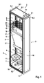
- the cooling device 2 shown in FIG. 1 has a rack 8 with vertical braces 8 . 1 and horizontal braces 8 . 2 , which form a parallelepiped assembly body and a system of holes, via which the components essential for cooling device 2 are mounted in the interior of rack 8 .
- the geometry of profile rails 8 . 1 and 8 . 2 can for example correspond to those of a customary frame profile, as it is known from electrical enclosure design, for example from DE 196 47 723 C1.
- an arrangement is configured of two fans 11 , via which the air to be cooled is transported via a hot air intake opening 7 through heat transfer device 12 , and is blown back as cooled air via cooling air blowoff opening 15 into the electrical enclosure (not shown).
- the hot air intake opening 7 adjoins a busbar transfer area 5 , which extends through between the opposing faces 3 of cooling device 2 , downwards, while busbar transfer area 5 is adjoined upwards via a roof element of cooling device 2 .
- Hot air intake opening 7 is accommodated in an upper side of cooling device housing 10 and is a removable grid frame, which adjoins an installation space 18 of busbar transfer area 5 .
- Installation space 18 is configured straight between heat transfer device 12 and the upper side 13 of housing 10 , and serves to admit an electrical control and regulation device 19 for operation of cooling device 2 , for example an inverter, so that control and regulation device 19 on the one hand is accommodated to be protected from undesired access, and on the other hand, for example in case of maintenance, is easily accessible by removal of upper side 13 .
- an electrical control and regulation device 19 for operation of cooling device 2 for example an inverter
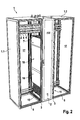
- FIG. 2 shows a perspective view of an embodiment of the electrical enclosure arrangement.
- the depicted electrical enclosure arrangement permits the busbars 4 to be able to run without interruption from electrical enclosure 1 . 1 shown on the left in the figure, through cooling device 2 , namely through busbar transfer area 5 to electrical enclosure 1 . 2 on the right in the figure.
- Housing 10 of cooling device 2 extends vertically directly to hot air intake opening 7 , which empties out into busbar transfer area 5 .
- a cooling air blowoff opening 15 is configured, which empties out into a lower area in the interior space 17 of left electrical enclosure 1 . 1 or into the interior space 17 of right electrical enclosure 1 . 2 .
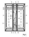
- FIG. 3 illustrates the air volume flow that results.
- the heated air in the interior spaces 17 of electrical enclosures 1 . 1 , 1 . 2 passes by the aligned, lateral openings 6 , via which the busbar transfer area 5 empties out into interior spaces 17 , into busbar transfer area 5 , in order from there to pass through hot air intake opening 7 of housing 10 of cooling device 2 into cooling device 2 .
- After the air to be cooled passes through heat transfer device 12 and thermal energy has been exchanged, it is directed from the fans 11 as cooled air via the lower lateral cool air blowout openings 15 into the lateral walls 16 (see FIGS. 1 and 2 ) of housing 10 , back into interior space 17 of electrical enclosures 1 . 1 , 1 . 2 .
- the air volume flow illustrated by the arrows is produced.
- FIG. 3 further shows that the rack of the two electrical enclosures 1 . 1 and 1 . 2 is identically configured in its vertical and depth measurements, so that a simple linear arrangement is produced via the rack from electrical enclosures 1 . 1 , 1 . 2 and cooling device 2 .
- This can occur with the aid of connection means known from prior art for electrical enclosure lines.
- sealing elements can also be configured between adjoining vertical and horizontal braces of rack 8 , in order to produce a fluid-sealed connection between cooling device 2 and the particular electrical enclosure 1 . 1 and 1 . 2 .
Landscapes
- Engineering & Computer Science (AREA)
- Microelectronics & Electronic Packaging (AREA)
- Physics & Mathematics (AREA)
- Thermal Sciences (AREA)
- Aviation & Aerospace Engineering (AREA)
- Computer Hardware Design (AREA)
- General Engineering & Computer Science (AREA)
- Cooling Or The Like Of Electrical Apparatus (AREA)
- Devices That Are Associated With Refrigeration Equipment (AREA)
- Patch Boards (AREA)
Abstract
Description
- This application is a 371 U.S. National Stage of International Application No. PCT/DE2016/100142, filed on Mar. 23, 2016, which claims priority to
German Application 10 2015 105 493.0, filed on Apr. 10, 2015. The entire disclosures of the above applications are incorporated herein by reference. - The invention derives from an electrical enclosure arrangement comprising an electrical enclosure line and a cooling device connected into the line, wherein the electrical enclosure line is formed from multiple electrical enclosures which are connected together.
- This section provides background information related to the present disclosure which is not necessarily prior art.
- One such electrical enclosure arrangement is known from DE 10 2012 007 707 A1. Until now, in order by a busbar to electrically connect electrical enclosures with electrical enclosure arrangements known from prior art, which are separated from each other by a cooling device situated between them, it has been necessary to direct the busbar outside the electrical enclosures, for example above the electrical enclosure body and out via the cooling device situated between them. However, this requires increased space and installation expense.
- This section provides a general summary of the disclosure, and is not a comprehensive disclosure of its full scope or all of its features.
- Therefore it is the object of the invention to further develop an electrical enclosure arrangement of the type described initially so that it permits a space-saving busbar direction between two electrical enclosures, which are separated from each other by a cooling device connected into the line.
- To achieve this end, the invention proposes an electrical enclosure arrangement with the features of claim 1. The dependent claims relate to advantageous embodiments of the invention.
- Accordingly, it is proposed that the cooling device suctions warm air from the electrical enclosures, from both the opposite faces via which it adjoins each of the electrical enclosures, and blows it as cooled air into the electrical enclosure, and wherein at least one busbar is directed between the electrical enclosures adjoining the cooling devices through a busbar transfer area of the cooling device.
- The cooling device does not need to be limited to any particular types of devices for generation of cooled air. The cooling device can for example be an air-refrigerant-heat exchanger given through-ventilation by a fan, which forms a refrigerant circuit via an approach device and a feedback device with an external refrigerant source, such as a chiller, a return cooler or a refrigerator, and is supplied with cooled refrigerant from this.
- The busbar transfer area can be opened via aligned openings in the two opposite faces toward the adjoining electrical enclosures and the at least one busbar can be guided by the aligned openings.
- This can be configured so that a hot air suction opening of the cooling device empties out into the busbar transfer area, so that hot air is guided by the aligned openings from the adjoining electrical enclosures through the busbar transfer area and the hot air suction opening through the cooling device.
- Provision can be made that the cooling device has a rack comprised of four vertical braces and eight horizontal braces, wherein within the installation space contoured by the rack a cooling device housing is mounted, in which at least one fan and a heat transfer device is arranged, which, on its upper side, via which the cooling device housing adjoins the busbar transfer area, has a hot air suction opening, and wherein hot air is suctioned from the at least one fan via the hot air suction opening, is directed through the heat transfer device and blown out via the cool air blowoff openings.
- Additionally, the cooling device housing can have one cooling air blowoff opening on each of two facing elements situated parallel to each other and perpendicular to the upper side, both of which empty out into one of the adjoining electrical enclosures. With this, the busbar transfer area can be that section of the installation space of the cooling device rack that is above the upper side of the cooling device housing.
- Likewise, the adjoining electrical enclosures can have an additional rack made of four vertical braces and eight horizontal braces, with the vertical braces and the lower braces of the three racks being dimensioned to have equal length, and with the rack of the cooling device connected on two opposite faces of the cooling device with the rack of the particular adjoining electrical enclosure, so that the inner spaces of the electrical enclosures are connected in fluid terms with each other via the busbar transfer area.
- Provision can further be made that directly beneath the upper side of the cooling device housing, an installation space is configured in which at least one electrical control and regulation device is placed for operation of the cooling device, for example an inverter. The upper side can be configured as a removable and air-permeable covering, especially as a rectangular grid frame, which at each of its corners is connected with one of the four vertical braces of the rack of the cooling device.
- Lastly, the hot air suction opening in the upper side of the cooling device housing can be in fluid connection via the installation space with an air inlet of the heat transfer device, so that the suctioned air flows through the installation space and directs out waste heat generated by the electrical control and regulation device.
- Further areas of applicability will become apparent from the description provided herein. The description and specific examples in this summary are intended for purposes of illustration only and are not intended to limit the scope of the present disclosure.
- The drawings described herein are for illustrative purposes only of selected embodiments and not all possible implementations, and are not intended to limit the scope of the present disclosure.
- Further particulars of the invention are clarified with the aid of the figures which follow. Shown area:
-
FIG. 1 a shows a perspective view of an embodiment of the invention-specific cooling device -
FIG. 2a shows a perspective view of an embodiment of the invention-specific electrical enclosure -
FIG. 3a shows a schematic depiction of the air flow formed in the electrical enclosure arrangement ofFIG. 2 . - Example embodiments will now be described more fully with reference to the accompanying drawings.
- The
cooling device 2 shown inFIG. 1 has arack 8 with vertical braces 8.1 and horizontal braces 8.2, which form a parallelepiped assembly body and a system of holes, via which the components essential forcooling device 2 are mounted in the interior ofrack 8. The geometry of profile rails 8.1 and 8.2 can for example correspond to those of a customary frame profile, as it is known from electrical enclosure design, for example from DE 196 47 723 C1. - In a lower area of assembly room 9, an arrangement is configured of two
fans 11, via which the air to be cooled is transported via a hot air intake opening 7 throughheat transfer device 12, and is blown back as cooled air via cooling air blowoff opening 15 into the electrical enclosure (not shown). The hot air intake opening 7 adjoins abusbar transfer area 5, which extends through between theopposing faces 3 ofcooling device 2, downwards, whilebusbar transfer area 5 is adjoined upwards via a roof element ofcooling device 2. Hotair intake opening 7 is accommodated in an upper side ofcooling device housing 10 and is a removable grid frame, which adjoins aninstallation space 18 ofbusbar transfer area 5.Installation space 18 is configured straight betweenheat transfer device 12 and the upper side 13 ofhousing 10, and serves to admit an electrical control andregulation device 19 for operation ofcooling device 2, for example an inverter, so that control andregulation device 19 on the one hand is accommodated to be protected from undesired access, and on the other hand, for example in case of maintenance, is easily accessible by removal of upper side 13. -
FIG. 2 shows a perspective view of an embodiment of the electrical enclosure arrangement. Especially perceptible is that the depicted electrical enclosure arrangement permits thebusbars 4 to be able to run without interruption from electrical enclosure 1.1 shown on the left in the figure, throughcooling device 2, namely throughbusbar transfer area 5 to electrical enclosure 1.2 on the right in the figure.Housing 10 ofcooling device 2 extends vertically directly to hotair intake opening 7, which empties out intobusbar transfer area 5. At the lower end of each of the facingelements 16 ofhousing 10 ofcooling device 2, a coolingair blowoff opening 15 is configured, which empties out into a lower area in theinterior space 17 of left electrical enclosure 1.1 or into theinterior space 17 of right electrical enclosure 1.2. -
FIG. 3 illustrates the air volume flow that results. The heated air in theinterior spaces 17 of electrical enclosures 1.1, 1.2 passes by the aligned,lateral openings 6, via which thebusbar transfer area 5 empties out intointerior spaces 17, intobusbar transfer area 5, in order from there to pass through hot air intake opening 7 ofhousing 10 ofcooling device 2 intocooling device 2. After the air to be cooled passes throughheat transfer device 12 and thermal energy has been exchanged, it is directed from thefans 11 as cooled air via the lower lateral coolair blowout openings 15 into the lateral walls 16 (seeFIGS. 1 and 2 ) ofhousing 10, back intointerior space 17 of electrical enclosures 1.1, 1.2. Thus the air volume flow illustrated by the arrows is produced. -
FIG. 3 further shows that the rack of the two electrical enclosures 1.1 and 1.2 is identically configured in its vertical and depth measurements, so that a simple linear arrangement is produced via the rack from electrical enclosures 1.1, 1.2 andcooling device 2. This can occur with the aid of connection means known from prior art for electrical enclosure lines. For example, sealing elements can also be configured between adjoining vertical and horizontal braces ofrack 8, in order to produce a fluid-sealed connection betweencooling device 2 and the particular electrical enclosure 1.1 and 1.2. - The features of the invention disclosed in the above specification, in the drawings and in the claims, can be essential for implementation of the invention both individually and in any combination.
- The foregoing description of the embodiments has been provided for purposes of illustration and description. It is not intended to be exhaustive or to limit the disclosure. Individual elements or features of a particular embodiment are generally not limited to that particular embodiment, but, where applicable, are interchangeable and can be used in a selected embodiment, even if not specifically shown or described. The same may also be varied in many ways. Such variations are not to be regarded as a departure from the disclosure, and all such modifications are intended to be included within the scope of the disclosure.
Claims (9)
Applications Claiming Priority (4)
| Application Number | Priority Date | Filing Date | Title |
|---|---|---|---|
| DE102015105493 | 2015-04-10 | ||
| DE102015105493.0 | 2015-04-10 | ||
| DE102015105493.0A DE102015105493B3 (en) | 2015-04-10 | 2015-04-10 | Control cabinet arrangement with a control cabinet row and a cooling unit arranged in it |
| PCT/DE2016/100142 WO2016162014A1 (en) | 2015-04-10 | 2016-03-23 | Electrical enclosure arrangement comprising an electrical enclosure line and a cooling device connected into the line |
Publications (2)
| Publication Number | Publication Date |
|---|---|
| US20180098456A1 true US20180098456A1 (en) | 2018-04-05 |
| US11044831B2 US11044831B2 (en) | 2021-06-22 |
Family
ID=56080205
Family Applications (1)
| Application Number | Title | Priority Date | Filing Date |
|---|---|---|---|
| US15/565,397 Active US11044831B2 (en) | 2015-04-10 | 2016-03-23 | Electrical enclosure arrangement comprising an electrical enclosure line and a cooling device connected into the line |
Country Status (7)
| Country | Link |
|---|---|
| US (1) | US11044831B2 (en) |
| EP (1) | EP3281506B1 (en) |
| JP (1) | JP6578011B2 (en) |
| CN (1) | CN107548534B (en) |
| DE (1) | DE102015105493B3 (en) |
| RU (1) | RU2671003C1 (en) |
| WO (1) | WO2016162014A1 (en) |
Cited By (7)
| Publication number | Priority date | Publication date | Assignee | Title |
|---|---|---|---|---|
| US20190124786A1 (en) * | 2016-04-22 | 2019-04-25 | Rittal Gmbh & Co. Kg | Electrical enclosure assembly comprising a cooling device which is received in an electrical enclosure housing |
| USD857639S1 (en) * | 2016-11-17 | 2019-08-27 | Cooper Technologies Company | Single door for electrical panel enclosure |
| US10537038B2 (en) | 2016-11-17 | 2020-01-14 | Eaton Intelligent Power Limited | Electrical panel enclosure including baffle to inhibit water ingress |
| US10947773B2 (en) | 2016-11-17 | 2021-03-16 | Cooper Technologies Company | One or more doors with one or more angled side flanges for electrical panel enclosure |
| EP3849293A4 (en) * | 2018-09-19 | 2021-11-10 | ZTE Corporation | Closed cold pool system |
| US20210361065A1 (en) * | 2020-05-20 | 2021-11-25 | Hoffman Enclosures, Inc. | Internal Side Panel for Enclosures |
| CN114025596A (en) * | 2022-01-06 | 2022-02-08 | 广东欢联电子科技有限公司 | Infrastructure of modularized multifunctional data center |
Families Citing this family (2)
| Publication number | Priority date | Publication date | Assignee | Title |
|---|---|---|---|---|
| CN110535039B (en) * | 2019-09-03 | 2021-06-08 | 许继变压器有限公司 | Switch board and integrative integrated type transformer station for transformer station |
| CN111834932B (en) * | 2020-07-21 | 2022-07-08 | 许昌学院 | Intelligent distribution network safety arrangement |
Citations (4)
| Publication number | Priority date | Publication date | Assignee | Title |
|---|---|---|---|---|
| US5481429A (en) * | 1991-03-18 | 1996-01-02 | Asea Brown Boveri Ab | Distribution of cooling air in switchgear cubicles |
| US20070081302A1 (en) * | 2004-02-17 | 2007-04-12 | Michael Nicolai | Assembly of devices |
| US7447022B2 (en) * | 2006-08-09 | 2008-11-04 | Hewlett-Packard Development Company, L.P. | Rack-mount equipment bay cooling heat exchanger |
| US20150003009A1 (en) * | 2012-03-12 | 2015-01-01 | Hewlett-Packard Development Company, L.P. | Rack cooling system with a cooling section |
Family Cites Families (18)
| Publication number | Priority date | Publication date | Assignee | Title |
|---|---|---|---|---|
| DE8807768U1 (en) * | 1988-06-15 | 1989-01-12 | Lohmeier Schaltschranksysteme Gmbh & Co Kg, 4973 Vlotho, De | |
| SE468028B (en) * | 1991-03-18 | 1992-10-19 | Asea Brown Boveri | PROVIDED TO BE GRANTED IN A SYSTEM OF STEEL MANUFACTURING AND DEVICE FOR IMPLEMENTATION OF THESE SADES |
| US5747734A (en) * | 1993-09-07 | 1998-05-05 | Siemens Stromberg-Carlson | Universal modular housing system |
| DE19647723C1 (en) | 1996-11-19 | 1998-04-09 | Loh Kg Rittal Werk | Frame-structure for switch cabinet |
| DE19804900C2 (en) * | 1998-02-07 | 2003-04-30 | Rittal Gmbh & Co Kg | switch cabinet |
| DE29901658U1 (en) * | 1999-02-03 | 2000-07-13 | Burn Heinz | Modular control cabinet system for accommodating electrical and electronic units |
| US6945616B2 (en) * | 2001-04-02 | 2005-09-20 | Emerson Network Power, Energy Systems, North America, Inc. | Modular enclosure system for electronic equipment |
| DE10325929A1 (en) * | 2003-06-07 | 2005-01-05 | Rittal Gmbh & Co. Kg | Cooling system for one or more control cabinets |
| DE202004015673U1 (en) * | 2004-02-17 | 2005-02-03 | Rittal Gmbh & Co. Kg | Climate controlled switching cabinet for electrical appliances, has a cooling unit with a housing space that can be matched to the size of cooling module required to cool the electrical and electronic equipment |
| DE102006058779A1 (en) * | 2006-12-12 | 2008-06-19 | Rittal Gmbh & Co. Kg | cabinet arrangement |
| JP4498367B2 (en) * | 2007-01-09 | 2010-07-07 | 三菱電機株式会社 | Power panel |
| GB2463956B (en) | 2008-05-20 | 2010-11-03 | Semper Holdings Ltd | Rack mounted cooling unit |
| KR100917379B1 (en) * | 2008-12-23 | 2009-09-16 | 주식회사 일신전기 | Distributing board for cubicle and transformer case |
| DE102012007707B4 (en) | 2012-04-19 | 2017-03-30 | Rittal Gmbh & Co. Kg | Cooling unit for cabinet cooling |
| DE102012110247A1 (en) | 2012-10-26 | 2014-04-30 | Eaton Industries (Austria) Gmbh | Switch cabinet with improved possibility for stringing together |
| CN103855628A (en) * | 2012-11-29 | 2014-06-11 | 西安上尚机电有限公司 | Semiconductor-based power distribution cabinet heat dissipation system |
| DE102012112505B3 (en) * | 2012-12-18 | 2014-06-18 | Rittal Gmbh & Co. Kg | Control cabinet with an arrangement for cooling, absorbed in an interior of the cabinet, heat-emitting components |
| EP2762810A1 (en) * | 2013-02-04 | 2014-08-06 | ABB Oy | Cooling assembly and dehumidification method |
-
2015
- 2015-04-10 DE DE102015105493.0A patent/DE102015105493B3/en active Active
-
2016
- 2016-03-23 CN CN201680010415.4A patent/CN107548534B/en active Active
- 2016-03-23 WO PCT/DE2016/100142 patent/WO2016162014A1/en active Application Filing
- 2016-03-23 EP EP16724841.8A patent/EP3281506B1/en active Active
- 2016-03-23 JP JP2017545629A patent/JP6578011B2/en active Active
- 2016-03-23 RU RU2017135517A patent/RU2671003C1/en active
- 2016-03-23 US US15/565,397 patent/US11044831B2/en active Active
Patent Citations (4)
| Publication number | Priority date | Publication date | Assignee | Title |
|---|---|---|---|---|
| US5481429A (en) * | 1991-03-18 | 1996-01-02 | Asea Brown Boveri Ab | Distribution of cooling air in switchgear cubicles |
| US20070081302A1 (en) * | 2004-02-17 | 2007-04-12 | Michael Nicolai | Assembly of devices |
| US7447022B2 (en) * | 2006-08-09 | 2008-11-04 | Hewlett-Packard Development Company, L.P. | Rack-mount equipment bay cooling heat exchanger |
| US20150003009A1 (en) * | 2012-03-12 | 2015-01-01 | Hewlett-Packard Development Company, L.P. | Rack cooling system with a cooling section |
Cited By (11)
| Publication number | Priority date | Publication date | Assignee | Title |
|---|---|---|---|---|
| US20190124786A1 (en) * | 2016-04-22 | 2019-04-25 | Rittal Gmbh & Co. Kg | Electrical enclosure assembly comprising a cooling device which is received in an electrical enclosure housing |
| US10765035B2 (en) * | 2016-04-22 | 2020-09-01 | Rittal Gmbh & Co. Kg | Electrical enclosure assembly comprising a cooling device which is received in an electrical enclosure housing |
| USD857639S1 (en) * | 2016-11-17 | 2019-08-27 | Cooper Technologies Company | Single door for electrical panel enclosure |
| US10537038B2 (en) | 2016-11-17 | 2020-01-14 | Eaton Intelligent Power Limited | Electrical panel enclosure including baffle to inhibit water ingress |
| US10947773B2 (en) | 2016-11-17 | 2021-03-16 | Cooper Technologies Company | One or more doors with one or more angled side flanges for electrical panel enclosure |
| USD914622S1 (en) | 2016-11-17 | 2021-03-30 | Eaton Intelligent Power Limited | Double doors for electrical panel enclosure |
| USD915311S1 (en) | 2016-11-17 | 2021-04-06 | Eaton Intelligent Power Limited | Single door for electrical panel enclosure |
| USD919584S1 (en) | 2016-11-17 | 2021-05-18 | Eaton Intelligent Power Limited | Double doors for electrical panel enclosure |
| EP3849293A4 (en) * | 2018-09-19 | 2021-11-10 | ZTE Corporation | Closed cold pool system |
| US20210361065A1 (en) * | 2020-05-20 | 2021-11-25 | Hoffman Enclosures, Inc. | Internal Side Panel for Enclosures |
| CN114025596A (en) * | 2022-01-06 | 2022-02-08 | 广东欢联电子科技有限公司 | Infrastructure of modularized multifunctional data center |
Also Published As
| Publication number | Publication date |
|---|---|
| EP3281506A1 (en) | 2018-02-14 |
| JP6578011B2 (en) | 2019-09-18 |
| CN107548534B (en) | 2020-08-07 |
| WO2016162014A1 (en) | 2016-10-13 |
| EP3281506B1 (en) | 2019-12-04 |
| RU2671003C1 (en) | 2018-10-29 |
| CN107548534A (en) | 2018-01-05 |
| DE102015105493B3 (en) | 2016-08-04 |
| JP2018511170A (en) | 2018-04-19 |
| US11044831B2 (en) | 2021-06-22 |
Similar Documents
| Publication | Publication Date | Title |
|---|---|---|
| US11044831B2 (en) | Electrical enclosure arrangement comprising an electrical enclosure line and a cooling device connected into the line | |
| US10375851B2 (en) | Electrical cabinet with improved heat dissipation | |
| US8072752B2 (en) | Electrical cabinet with two cooling channels | |
| CA2520878C (en) | Cooling system for equipment and network cabinets and method for cooling equipment and network cabinets | |
| CN101027951A (en) | Cooling system for appliance and network cabinets, and method for cooling appliance and network cabinets | |
| US10524382B2 (en) | System and method for forced air cooling of electrical device | |
| EP3095308B1 (en) | Cabinet for electronic equipment | |
| US11116111B2 (en) | Method and arrangement for air-conditioning a cold aisle | |
| US9883608B2 (en) | Cooling device for cooling a switchgear cabinet | |
| JP2008198877A (en) | Electronic equipment housing apparatus | |
| RU2515530C2 (en) | Device of conditioning for cooling of air in cabinet for electronic devices | |
| CN110785057A (en) | Integrated unit cabinet with vertical air duct | |
| US20180010836A1 (en) | Heat transfer unit | |
| US10236666B2 (en) | Air conditioning arrangement | |
| CN107432100B (en) | Cooling device for air conditioning of a switchgear cabinet | |
| CN201388355Y (en) | Heat dissipating device and electronic part module box and machine room with heat dissipating devices | |
| ES2951289T3 (en) | Air conditioning layout | |
| US10631433B2 (en) | Door cooler | |
| US20110036961A1 (en) | Modular Apparatus and Assembly | |
| WO2019045668A1 (en) | System and method of forced air cooling for electrical device | |
| JP2018098867A (en) | Power converter | |
| KR102436609B1 (en) | Air conditioned room | |
| JP2016111194A (en) | Control board | |
| JP2016200334A (en) | Refrigeration cycle device | |
| KR20170001974A (en) | Electric and Electronic Equipment Cooling System |
Legal Events
| Date | Code | Title | Description |
|---|---|---|---|
| FEPP | Fee payment procedure |
Free format text: ENTITY STATUS SET TO UNDISCOUNTED (ORIGINAL EVENT CODE: BIG.); ENTITY STATUS OF PATENT OWNER: LARGE ENTITY |
|
| AS | Assignment |
Owner name: RITTAL GMBH & CO. KG, GERMANY Free format text: ASSIGNMENT OF ASSIGNORS INTEREST;ASSIGNORS:SCHREIER, CHRISTOPH;EIBACH, STEFAN;REITZ, CHRISTOPH;AND OTHERS;SIGNING DATES FROM 20171002 TO 20171005;REEL/FRAME:044174/0095 |
|
| STCV | Information on status: appeal procedure |
Free format text: NOTICE OF APPEAL FILED |
|
| STCV | Information on status: appeal procedure |
Free format text: APPEAL BRIEF (OR SUPPLEMENTAL BRIEF) ENTERED AND FORWARDED TO EXAMINER |
|
| STCV | Information on status: appeal procedure |
Free format text: EXAMINER'S ANSWER TO APPEAL BRIEF MAILED |
|
| STCV | Information on status: appeal procedure |
Free format text: ON APPEAL -- AWAITING DECISION BY THE BOARD OF APPEALS |
|
| STCV | Information on status: appeal procedure |
Free format text: BOARD OF APPEALS DECISION RENDERED |
|
| STPP | Information on status: patent application and granting procedure in general |
Free format text: NOTICE OF ALLOWANCE MAILED -- APPLICATION RECEIVED IN OFFICE OF PUBLICATIONS |
|
| STPP | Information on status: patent application and granting procedure in general |
Free format text: PUBLICATIONS -- ISSUE FEE PAYMENT RECEIVED |
|
| STPP | Information on status: patent application and granting procedure in general |
Free format text: PUBLICATIONS -- ISSUE FEE PAYMENT VERIFIED |
|
| STCF | Information on status: patent grant |
Free format text: PATENTED CASE |