US20180098375A1 - Apparatus and method to control reconnection of a terminal device to a wireless network via another wireless network - Google Patents
Apparatus and method to control reconnection of a terminal device to a wireless network via another wireless network Download PDFInfo
- Publication number
- US20180098375A1 US20180098375A1 US15/704,117 US201715704117A US2018098375A1 US 20180098375 A1 US20180098375 A1 US 20180098375A1 US 201715704117 A US201715704117 A US 201715704117A US 2018098375 A1 US2018098375 A1 US 2018098375A1
- Authority
- US
- United States
- Prior art keywords
- access point
- wireless network
- disconnected
- tablet terminal
- unit
- Prior art date
- Legal status (The legal status is an assumption and is not a legal conclusion. Google has not performed a legal analysis and makes no representation as to the accuracy of the status listed.)
- Granted
Links
- 238000000034 method Methods 0.000 title claims description 63
- 238000004891 communication Methods 0.000 claims abstract description 27
- 230000008569 process Effects 0.000 claims description 48
- 230000005540 biological transmission Effects 0.000 claims description 13
- 239000000284 extract Substances 0.000 claims description 3
- 238000012544 monitoring process Methods 0.000 description 26
- 238000010586 diagram Methods 0.000 description 24
- 238000012545 processing Methods 0.000 description 18
- 230000006870 function Effects 0.000 description 13
- 238000011084 recovery Methods 0.000 description 12
- 230000004044 response Effects 0.000 description 4
- 238000005516 engineering process Methods 0.000 description 3
- 230000008901 benefit Effects 0.000 description 2
- 230000000694 effects Effects 0.000 description 2
- 230000010365 information processing Effects 0.000 description 2
- 238000012806 monitoring device Methods 0.000 description 2
- 230000004075 alteration Effects 0.000 description 1
- 230000008859 change Effects 0.000 description 1
- 230000003111 delayed effect Effects 0.000 description 1
- 238000001514 detection method Methods 0.000 description 1
- 230000005674 electromagnetic induction Effects 0.000 description 1
- 230000010354 integration Effects 0.000 description 1
- 238000012423 maintenance Methods 0.000 description 1
- 230000008520 organization Effects 0.000 description 1
- 238000006467 substitution reaction Methods 0.000 description 1
- 230000001360 synchronised effect Effects 0.000 description 1
Images

Classifications
-
- H04W76/028—
-
- H—ELECTRICITY
- H04—ELECTRIC COMMUNICATION TECHNIQUE
- H04W—WIRELESS COMMUNICATION NETWORKS
- H04W76/00—Connection management
- H04W76/10—Connection setup
- H04W76/19—Connection re-establishment
-
- H04L61/2038—
-
- H—ELECTRICITY
- H04—ELECTRIC COMMUNICATION TECHNIQUE
- H04L—TRANSMISSION OF DIGITAL INFORMATION, e.g. TELEGRAPHIC COMMUNICATION
- H04L61/00—Network arrangements, protocols or services for addressing or naming
- H04L61/50—Address allocation
- H04L61/5038—Address allocation for local use, e.g. in LAN or USB networks, or in a controller area network [CAN]
-
- H—ELECTRICITY
- H04—ELECTRIC COMMUNICATION TECHNIQUE
- H04W—WIRELESS COMMUNICATION NETWORKS
- H04W48/00—Access restriction; Network selection; Access point selection
- H04W48/08—Access restriction or access information delivery, e.g. discovery data delivery
- H04W48/10—Access restriction or access information delivery, e.g. discovery data delivery using broadcasted information
-
- H—ELECTRICITY
- H04—ELECTRIC COMMUNICATION TECHNIQUE
- H04L—TRANSMISSION OF DIGITAL INFORMATION, e.g. TELEGRAPHIC COMMUNICATION
- H04L2101/00—Indexing scheme associated with group H04L61/00
- H04L2101/60—Types of network addresses
- H04L2101/618—Details of network addresses
- H04L2101/622—Layer-2 addresses, e.g. medium access control [MAC] addresses
Definitions
- the embodiments discussed herein are related to apparatus and method to control reconnection of a terminal device to a wireless network via another wireless network.
- one tablet computer per 3.6 students is deployed by the year 2017 and one per one student is deployed by the year 2020, and an achievement rate of 100% in maintenance of a wireless local area network (LAN) is planned.
- LAN wireless local area network
- a wireless LAN access point hereinafter, may be referred to as “AP”
- AP wireless LAN access point
- a tablet for teacher a tablet for student in each of classrooms.
- AP wireless LAN access point
- a technology in which when a terminal device such as a tablet or the like is coupled to another terminal device via a wireless LAN and disconnection from the wireless LAN is detected, a user performs a connection procedure with a wired LAN is known.
- Japanese Laid-open Patent Publication No. 2005-175814 is an example of the related art.
- an apparatus obtains connection status information of each of terminal devices coupled to a first wireless network via an access point, from the access point.
- the apparatus detects a disconnected device which is a terminal device whose communication with the access point is disconnected, with reference to the connection status information, and notifies, via a second wireless network, the disconnected device of a reconnection instruction for instructing the disconnected device to reconnect to the first wireless network by accessing the access point.
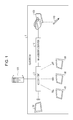
- FIG. 1 is a diagram illustrating an example of an overall configuration of a system, according to an embodiment
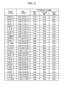
- FIG. 2 is a diagram illustrating an example of a functional configuration of each of devices, according to an embodiment
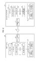
- FIG. 3 is a diagram illustrating an example of information stored in a beacon pattern database (DB), according to an embodiment
- FIG. 4 is a diagram illustrating an example of information stored in a connection status DB, according to an embodiment
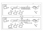
- FIG. 5 is a diagram illustrating an example of automatic recovery, according to an embodiment
- FIG. 6 is a diagram illustrating an example of an operational flowchart for a process of a management computer, according to an embodiment
- FIG. 7 is a diagram illustrating an example of an operational flowchart for a process of a tablet terminal, according to an embodiment
- FIG. 8 is a diagram illustrating an example of automatic recovery, according to an embodiment
- FIG. 9 is a diagram illustrating an example of a functional configuration of each of devices, according to an embodiment.
- FIG. 10 is a diagram illustrating an example of information stored in an address information DB, according to an embodiment
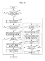
- FIG. 11 is a diagram illustrating an example of an operational flowchart for a process of a management computer, according to an embodiment
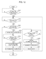
- FIG. 12 is a diagram illustrating an example of an operational flowchart for a process of a tablet terminal, according to an embodiment
- FIG. 13 is a diagram illustrating an example of a hardware configuration of a management computer, according to an embodiment.
- FIG. 14 is a diagram illustrating an example of a hardware configuration of a tablet terminal, according to an embodiment.
- a tablet terminal has a function of constantly monitoring communication with AP, and a function of executing restarting of an operating system (OS) of the tablet and executing AP reconnection when detecting disconnection.
- OS operating system
- a screen display or the like is delayed when these functions are included.
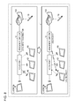
- FIG. 1 is a diagram illustrating an overall configuration example of a system according to Example 1.
- Example 1 as an example, a school class or the like is assumed.
- a wireless LAN is built in a classroom, tablet terminals are distributed to each student and teacher, and a class is held by displaying information such as a textbook on the tablet terminals by using the wireless LAN.
- FIG. 1 illustrates a classroom 1 and a server 120 installed outside the classroom 1 .
- a wireless LAN such as a Wireless-Fidelity (Wi-Fi)® is built and the classroom 1 includes an access point 2 , a management computer 10 , a tablet terminal 30 for teacher, tablet terminals 40 , 60 , and 80 for students, an electronic blackboard projector 100 , and an electronic pen 110 .
- Wi-Fi Wireless-Fidelity
- the access point 2 is an example of a device which connects each of tablet terminals in the classroom 1 to a wireless LAN and connects the external server 120 to the wireless LAN in the classroom 1 , and is generally a computer such as a router, a station, for example.
- the tablet terminal 30 for teacher and the tablet terminals 40 , 60 , and 80 for students are examples of portable mobile terminals and are computers having a touch panel, a wireless connection function, and the like. These tablet terminals are equipped with processors having lower performance than an ordinary personal computer for the purpose of reducing the thickness and weight, and the battery operation.
- these tablet terminals are coupled to a wireless LAN via the access point 2 and are coupled to each other so as to communicate with each other. Further, each of the tablet terminals is coupled to the external server 120 via the access point 2 .
- Each of the tablet terminals displays textbook data delivered from the management computer 10 or the server 120 . Here, a class is held using textbook data instead of an ordinary textbook.
- the management computer 10 is an example of a computer such as a monitoring device and is coupled to the access point 2 via a wireless LAN or a wired line.
- the management computer 10 obtains textbook data from the server 120 via the access point 2 and delivers the data to each of the tablet terminals coupled to a wireless LAN via the access point 2 .
- the electronic blackboard projector 100 is coupled to the management computer 10 via a wired line such as a High-Definition Multimedia Interface (HDMI)®.
- the electronic blackboard projector 100 projects various images and videos input from the management computer 10 on a screen.
- the electronic blackboard projector 100 is coupled to the electronic pen 110 via infrared rays or the like and projects operation information by the electronic pen 110 on the screen together with various images and videos input from the management computer 10 .
- the server 120 is an example of an external server which is coupled to the access point 2 and holds textbook data. Upon receiving a request for data acquisition from each of the tablet terminals or the management computer 10 , the server 120 transmits the textbook data to a request destination via the access point 2 .
- the management computer 10 obtains, from the access point 2 , connection status of each of the tablet terminals coupled to a wireless LAN via the access point 2 .
- the management computer 10 detects a tablet terminal (hereinafter, sometimes described as “disconnected tablet”) disconnected from communication with the access point 2 . Thereafter, the management computer 10 notifies, by using a Bluetooth® Low Energy (BLE) beacon, the disconnected tablet being disconnected from a wireless LAN of a reconnection instruction for instructing the disconnected tablet to reconnect with a wireless LAN by accessing the access point 2 .
- BLE Bluetooth® Low Energy
- the management computer 10 transmits the reconnection instruction for reconnection with a wireless LAN, by using a BLE beacon.
- the tablet terminal disconnected from a wireless LAN may automatically reconnect with a wireless LAN without a teacher or a student performing recovery operation.
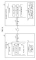
- FIG. 2 is a functional block diagram illustrating a functional configuration of each of devices according to Example 1.
- the management computer 10 includes a communication unit 11 , a storage unit 12 , and a controller 15 .
- the communication unit 11 is a processing unit which controls various communications such as a wireless communication or a wire communication.
- the communication unit 11 is coupled to a wireless LAN via the access point 2 , transmits information to each of the tablet terminals in a wireless LAN, and receives various kinds of information from each of the tablet terminals.
- the communication unit 11 receives connection status from the access point 2 and transmits textbook data to each of the tablet terminals.
- the communication unit 11 executes transmission control of a BLE beacon or the like.
- the storage unit 12 is a storage device which stores a program executed by the controller 15 or various kinds of data and is, for example, a memory or a hard disk.
- the storage unit 12 stores a beacon pattern DB 13 or a connection status DB 14 .
- the beacon pattern DB 13 is a database storing a beacon pattern which is a combination of channels of transmission frequencies of a BLE beacon.
- the beacon pattern DB 13 is a combination of advertising channels used in the BLE beacon and stores identification information used for identifying a tablet terminal of each student.
- FIG. 3 is a diagram illustrating an example of information stored in the beacon pattern DB 13 .
- the beacon pattern DB 13 stores “tablet terminal”, “media access control (MAC) address”, and “transmission channel (first time, second time, and third time)” in association with each other.
- “tablet terminal” is a name of a tablet terminal used by a student
- “MAC address” is a MAC address of the tablet terminal for each student.
- “transmission channel” is channel information of an advertising channel
- “first time”, “second time”, and “third time” are advertising channels used by a BLE beacon.
- connection status DB 14 is a database which stores connection status of each of the tablet terminals coupled to a wireless LAN. Information stored here may be collected by the access point 2 .
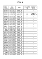
- FIG. 4 is a diagram illustrating an example of information stored in the connection status DB 14 .
- the connection status DB 14 stores “tablet terminal”, “MAC address”, “status”, “disconnection time”, and “disconnection reason” in association with each other.
- “tablet terminal” is a name of a tablet terminal used by a student
- “MAC address” is a MAC address of the tablet terminal for each student.
- “tablet terminal” and “MAC address” may be preset.
- connection status indicates connection status and stores “connecting” or “unconnected”.
- connection time is disconnected time.
- connection reason indicates whether or not a tablet terminal is disconnected during a class, and is set at “unexpected disconnection” in a case where the tablet terminal is disconnected during the class. “disconnection reason” may be determined by the access point 2 or the management computer 10 .
- FIG. 4 illustrates that in a tablet terminal of a student C of which a MAC address is “A1:B2:C3:F3:E2:D3”, “unexpected disconnection” occurs at “9:45” and the other tablet terminals of the other students are normally connected.
- the controller 15 is a processing unit which manages whole of the management computer 10 and is, for example, a processor or the like.
- the controller 15 includes a pattern generating unit 16 , a delivering unit 17 , a monitoring unit 18 , and an instruction notification unit 19 .
- the pattern generating unit 16 , the delivering unit 17 , the monitoring unit 18 , and the instruction notification unit 19 are an example of an electronic circuit included in a processor or the like or an example of a process executed by the processor.
- the pattern generating unit 16 is a processing unit which generates a combination of advertising channels for identifying each of the tablet terminals. For example, the pattern generating unit 16 generates a beacon pattern illustrated in FIG. 3 , and saves the beacon pattern in the beacon pattern DB 13 at a class start time. In addition, the pattern generating unit 16 also may delete information stored in the beacon pattern DB 13 at a class end time. The class start time or the class end time may be preset. In addition, as a generating method, it is possible to adopt a BLE random address setting and the like, and to arbitrarily change a combination of channels or the number of times of transmission, depending on the number of tablet terminals.
- the delivering unit 17 is a processing unit which delivers the beacon pattern generated by the pattern generating unit 16 to each of the tablet terminals via a wireless LAN. For example, when a beacon pattern is saved in the beacon pattern DB 13 , the delivering unit 17 reads the beacon pattern from the beacon pattern DB 13 and transmits the beacon pattern, via the access point 2 , to each of the tablet terminals by using “MAC address” stored in advance in the connection status DB 14 .
- the monitoring unit 18 is a processing unit which monitors connection status of a tablet terminal to a wireless LAN for each student. For example, the monitoring unit 18 obtains connection status (status, disconnection time, and the like) from the access point 2 , and monitors whether or not unexpected disconnection occurs. For example, the monitoring unit 18 regularly obtains connection status from the access point 2 and saves the obtained connection status in the connection status DB 14 . Then, in a case of detecting status “unconnected” during a class, the monitoring unit 18 sets “unexpected disconnection” to “disconnection reason” for a tablet terminal from which status “unconnected” has been detected.
- the instruction notification unit 19 is a processing unit which notifies a tablet terminal to which “unexpected disconnection” is set by the monitoring unit 18 , by using BLE different from a wireless LAN, of an instruction for reconnection to a wireless LAN by accessing the access point 2 .
- the instruction notification unit 19 specifies a combination of transmission channels corresponding to a tablet terminal for student in a disconnected state, from the beacon pattern DB 13 , and broadcasts an instruction for reconnection by using the specified combination.
- the instruction notification unit 19 upon detecting that “unexpected disconnection” is set to a tablet terminal of the student C with reference to the connection status DB 14 , the instruction notification unit 19 obtains disconnection time “9:45” from the connection status DB 14 . Next, the instruction notification unit 19 obtains transmission channels (37 ch, 37 ch, and 39 ch) of the tablet terminal of the student C in a disconnected state, from the beacon pattern DB 13 . Then, the instruction notification unit 19 broadcasts an advertised packet including time information “9:45” which is disconnection time, as a BLE beacon via 37 ch. After a predetermined time (for example, 30 seconds), the instruction notification unit 19 broadcasts an advertised packet including time information “9:45” as a BLE beacon via 37 ch. Further, after a predetermined time (for example, 30 seconds), the instruction notification unit 19 broadcasts an advertised packet including time information “9:45” as a BLE beacon via 39 ch.
- a predetermined time for example, 30 seconds
- the instruction notification unit 19 broadcasts
- the BLE beacon may include a reconnection instruction, a reconnection command, or the like.
- the predetermined time may be arbitrarily changed.
- Bluetooth® device address which may be an attack target when acquired by a third party, is not included in the beacon, security is high and risk of becoming the attack target of the third party becomes also small.
- the instruction notification unit 19 determines that a class is ended and deletes a beacon pattern stored in the beacon pattern DB 13 .
- the tablet terminal 40 includes a communication unit 41 , a display unit 42 , a storage unit 43 , and a controller 46 .
- the communication unit 41 is a processing unit which is coupled to a wireless LAN via the access point 2 and controls communication with another tablet terminal, the management computer 10 , the server 120 , and the like. For example, the communication unit 41 receives textbook data from the management computer 10 via the access point 2 .
- the communication unit 41 receives a BLE beacon broadcasted from the management computer 10 .
- the communication unit 41 receives an advertised packet including time information and the like from the management computer 10 without going through the access point 2 .
- the display unit 42 is a touch panel display which displays each piece of information and accepts operation of a student or the like.
- the display unit 42 displays textbook data and accepts page turning operation, answer operation to a problem, or the like.
- the storage unit 43 is a storage device which stores a program executed by the controller 46 or various kinds of data and is, for example, a memory or a hard disk.
- the storage unit 43 stores a beacon pattern DB 44 and a disconnection time DB 45 .
- the beacon pattern DB 44 is a database which stores a beacon pattern which is a combination of transmission frequency channels of a BLE beacon.
- the beacon pattern DB 44 stores a beacon pattern delivered from the management computer 10 .
- the stored information is the same as in FIG. 3 , and a detailed description thereof will be omitted.
- the disconnection time DB 45 is a database which stores a time at which the tablet terminal 40 is disconnected from a wireless LAN.
- the disconnection time DB 45 stores disconnection time “9:45” and the like.
- the stored disconnection time is the latest disconnection time and is updated by the controller 46 .
- the controller 46 is a processing unit which manages the overall tablet terminal 40 and is, for example, a processor or the like.
- the controller 46 includes a display controller 47 , a receiver 48 , and a reconnection unit 49 .
- the display controller 47 , the receiver 48 , and the reconnection unit 49 are an example of an electronic circuit included in a processor or the like or an example of a process executed by the processor.
- the controller 46 Upon detecting a tablet disconnected from a wireless LAN, the controller 46 determines whether or not disconnected time is in a time zone designated in advance such as a time zone in which a class is ended. In a case where the disconnected time is not in the time zone designated in advance, the controller 46 makes a determination of unexpected disconnection and saves the disconnection time in the disconnection time DB 45 . On the other hand, in a case where the disconnected time is in the time zone designated in advance, the controller 46 makes a determination of a class being ended and deletes information stored in the beacon pattern DB 44 .
- the display controller 47 is a processing unit which executes an information display or touch panel operation.
- the display controller 47 displays textbook data received from the management computer 10 on the display unit 42 .
- the display controller 47 accepts touch panel operation via the display unit 42 and executes a process corresponding to the accepted touch panel operation.
- the display controller 47 executes page turning when swipe operation is accepted and executes an enlarged display when receiving double click operation.
- the receiver 48 is a processing unit which receives a beacon pattern delivered from the management computer 10 .
- the receiver 48 receives a beacon pattern from the management computer 10 via the access point 2 and saves the beacon pattern in the beacon pattern DB 44 .
- the reconnection unit 49 is a processing unit which executes reconnection to a wireless LAN according to a reconnection instruction from the management computer 10 .
- the reconnection unit 49 receives a BLE beacon with a beacon pattern assigned to the tablet terminal 40 and executes reconnection in a case where disconnection time notified with the received BLE beacon matches with disconnection time stored in the disconnection time DB 45 .
- the reconnection unit 49 specifies that a beacon pattern assigned to the tablet terminal 40 is 37 ch, 37 ch, and 39 ch with reference to the beacon pattern DB 44 . Thereafter, the reconnection unit 49 receives an advertised packet of a BLE beacon broadcasted from the management computer 10 via 37 ch, subsequently receives an advertised packet of a BLE beacon broadcasted via 37 ch, and lastly receives an advertised packet of a BLE beacon broadcasted via 39 ch.
- the reconnection unit 49 determines that the advertised packets are addressed to the tablet terminal 40 .
- the reconnection unit 49 extracts time information from each of the received three advertised packets, and restarts the tablet terminal 40 and reconnects to a wireless LAN in a case where each piece of time information is equal to disconnection time (9:45) stored in the disconnection time DB 45 .
- a reconnection process is not limited to rebooting but can also include executing a command and the like designated in advance.
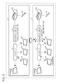
- FIG. 5 is a diagram for explaining automatic recovery according to Example 1.
- a class is held by the tablet terminal 30 for teacher, the tablet terminals 40 , 60 , and 80 for students, and the management computer 10 being coupled to each other by a wireless LAN via the access point 2 .
- the tablet terminal 40 is disconnected from the access point 2 .
- the management computer 10 obtains connection status from the access point 2 and detects unexpected disconnection of the tablet terminal 40 (S 1 ). At this time, the management computer 10 obtains disconnection time from the connection status.
- the management computer 10 specifies a beacon pattern assigned to the tablet terminal 40 from the beacon pattern DB 13 and broadcasts an advertised packet including the disconnection time by using the specified beacon pattern (S 2 ).
- each of the tablet terminals 40 , 60 , and 80 receives the advertised packets.
- the tablet terminal 40 among the tablet terminals 40 , 60 , and 80 receives the advertised packets with a beacon pattern assigned to the tablet terminal 40
- the tablet terminal 40 determines that the advertised packets are addressed to the tablet terminal 40 .
- disconnection time included in each of the advertised packets matches with disconnection time stored in the disconnection time DB 45 of the tablet terminal 40
- the tablet terminal 40 executes restarting (S 3 ).
- the management computer 10 executes automatic connection of a tablet terminal disconnected from a wireless LAN via a wireless network different from a wireless LAN.
- a process of each of devices will be described.
- a process of the management computer 10 and a process of a disconnected tablet terminal will be described.
- a disconnected tablet terminal is the tablet terminal 40 .
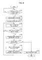
- FIG. 6 is a flowchart illustrating a flow of a process of the management computer 10 according to Example 1.
- the pattern generating unit 16 of the management computer 10 when connection of all of tablet terminals is completed (Yes in S 101 ), the pattern generating unit 16 of the management computer 10 generates a beacon pattern (S 102 ). Thereafter, the delivering unit 17 delivers the beacon pattern to each of the tablet terminals via the access point 2 (S 103 ).
- the pattern generating unit 16 may receive a notification of connection completion from the access point 2 or may also determine the connection completion from connection status obtained from the access point 2 .
- the monitoring unit 18 determines whether or not an unconnected tablet terminal exists (S 105 ).
- the monitoring unit 18 stores a disconnection reason and the like in the connection status DB 14 .
- the monitoring unit 18 repeats S 104 and the following steps.
- the instruction notification unit 19 specifies a beacon pattern corresponding to a tablet terminal of “unexpected disconnection” from the beacon pattern DB 13 (S 108 ).
- the instruction notification unit 19 transmits an advertised packet including the disconnection time with the corresponding beacon pattern as a BLE beacon (S 109 ). Thereafter, S 104 and the following steps are repeated.
- the instruction notification unit 19 determines that a class is ended and deletes a beacon pattern stored in the beacon pattern DB 13 (S 110 ).
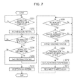
- FIG. 7 is a flowchart illustrating a flow of a process of the tablet terminal 40 according to Example 1.
- the receiver 48 of the tablet terminal 40 receives a beacon pattern by a wireless LAN via the access point 2 and saves the beacon pattern in the beacon pattern DB 44 (S 202 ).
- the controller 46 determines whether or not a disconnection reason is unexpected disconnection (S 204 ).
- the controller 46 saves the disconnection time in the disconnection time DB 45 (S 205 ).
- the reconnection unit 49 extracts disconnection time from each of advertised packets transmitted as a BLE beacon (S 208 ).
- the reconnection unit 49 executes a reconnecting process (S 210 ) and reconnects to a wireless LAN (S 211 ). Thereafter, S 203 and the following steps are repeated.
- the flow returns to S 206 and the reconnection unit 49 waits for receiving a BLE beacon.
- the controller 46 deletes a beacon pattern from the beacon pattern DB 44 (S 212 ).
- the management computer 10 may be automatically recovered from a trouble of a wireless LAN connection without going through a person. As a result, it is possible to provide an environment which minimizes class stop time.
- Example 1 an example in which a reconnection instruction is notified to a tablet terminal in a state of the tablet terminal being disconnected by using a beacon pattern and broadcasting is described, but the example is not limited thereto.
- BT Bluetooth®
- FIG. 8 is a diagram for explaining automatic recovery according to Example 2.
- An overall configuration of a system illustrated in FIG. 8 is the same as that of Example 1.
- the management computer 10 obtains connection status from the access point 2 and detects unexpected disconnection of the tablet terminal 40 (S 11 ). At this time, the management computer 10 obtains disconnection time from the connection status.
- the management computer 10 directly connects to the tablet terminal 40 during the disconnection from a wireless LAN by using BT, and issues a restarting command to the tablet terminal 40 (S 12 ). As a result, the tablet terminal 40 is able to automatically reconnect to a wireless LAN (S 13 ).
- FIG. 9 is a functional block diagram illustrating a functional configuration of each of devices according to Example 2.
- the management computer 10 includes the communication unit 11 , the storage unit 12 , and the controller 15 .
- the storage unit 12 is a storage device which stores a program executed by the controller 15 or various kinds of data and is, for example, a memory or a hard disk.
- the storage unit 12 stores the connection status DB 14 and an address information DB 20 .
- the address information DB 20 is address information used for BT connection and stores a Bluetooth® Device address (BD address) of each of the tablet terminals. Information stored therein is set and changed by an administrator or the like.
- BD address Bluetooth® Device address
- FIG. 10 is a diagram illustrating an example of information stored in the address information DB 20 .
- the address information DB 20 stores “tablet terminal”, “MAC address”, and “BD address” in association with each other.
- “tablet terminal” is a name of a tablet terminal used by a student
- “MAC address” is a MAC address of the tablet terminal for each student.
- “BD address” is address information used for BT connection.
- a MAC address of a tablet terminal of the student C is “A1:B2:C3:F3:E2:D3” and a BD address thereof is “B1:C2:D3:G3:F2:E3”.
- the controller 15 is a processing unit which manages the whole of the management computer 10 and is, for example, a processor or the like.
- the controller 15 includes a monitoring unit 21 , an establishing unit 22 , and a reconnection unit 23 .
- the monitoring unit 21 , the establishing unit 22 , and the reconnection unit 23 are an example of an electronic circuit included in a processor or the like or an example of a process executed by the processor.
- the monitoring unit 21 executes the same process as the monitoring unit 18 described Example 1. For example, the monitoring unit 21 obtains connection status (status and disconnection time) from the access point 2 and monitors whether or not unexpected disconnection occurs. For example, the monitoring unit 21 regularly obtains connection status from the access point 2 and saves the obtained connection status in the connection status DB 14 . Then, in a case of detecting status “unconnected” during a class, the monitoring unit 21 sets “unexpected disconnection” to “disconnection reason” of a tablet terminal corresponding to “unconnected”.
- connection status status
- the monitoring unit 21 sets “unexpected disconnection” to “disconnection reason” of a tablet terminal corresponding to “unconnected”.
- the establishing unit 22 is a processing unit which establishes BT connection with a tablet terminal being disconnected from wireless LAN. For example, upon detecting, with reference to the connection status DB 14 , a tablet terminal for which “unexpected disconnection” is registered, the establishing unit 22 specifies a BD address of the corresponding tablet terminal from the address information DB 20 . The establishing unit 22 executes BT connection by designating the specified BD address and establishes BT connection with the tablet terminal being disconnected from wireless LAN.
- the establishing unit 22 upon detecting “unexpected disconnection” of a tablet terminal of the student C with reference to the connection status DB 14 , the establishing unit 22 obtains a BD address “B1:C2:D3:G3:F2:E3” of the tablet terminal of the student C from the address information DB 20 .
- the establishing unit 22 designates the BD address “B1:C2:D3:G3:F2:E3” to transmit a BT connection request. Thereafter, upon receiving a connection response, the establishing unit 22 establishes BT connection with a tablet terminal of the student C to which the BD address “B1:C2:D3:G3:F2:E3” is set.
- the reconnection unit 23 is a processing unit which causes the tablet terminal disconnected from a wireless LAN to execute a reconnecting process. For example, the reconnection unit 23 issues start operation or a command of the reconnecting process by BT communication to the tablet terminal in which BT connection is established by the establishing unit 22 . In the above example, the reconnection unit 23 issues a command or the like of restarting by BT connection to the tablet terminal of the student C in which BT connection is established.
- the reconnection unit 23 When the tablet terminal of the student C is restarted, the reconnection unit 23 automatically establishes BT connection with the tablet terminal of the student C. Then, the reconnection unit 23 determines that reconnection to a wireless LAN is completed and automatically disconnects BT connection.
- the tablet terminal 40 includes the communication unit 41 , the display unit 42 , the storage unit 43 , and the controller 46 .
- Example 1 A difference from FIG. 2 described in Example 1 is that the storage unit 43 does not store the beacon pattern DB 44 .
- the reconnection unit 49 of the controller 46 includes a process different from Example 1, the process will be described.
- the reconnection unit 49 is a processing unit which establishes BT connection with the management computer 10 and receives an instruction for a reconnecting process via the BT connection, in contrast with Example 1. For example, in a case where “unexpected disconnection” is detected by the controller 46 , the reconnection unit 49 moves to a waiting state for BT connection. Thereafter, upon receiving a connection request by BT from the management computer 10 , the reconnection unit 49 transmits a connection response to the management computer 10 by using BT.
- the reconnection unit 49 in a state in which the reconnection unit 49 may not be connected to a wireless LAN, the reconnection unit 49 establishes BT connection with the management computer 10 . Thereafter, the reconnection unit 49 receives a restarting command or the like from the management computer 10 via BT connection.
- the tablet terminal 40 executes restarting by receiving a restarting command from the management computer 10 . Restarting may be performed remotely by the management computer 10 or performed locally by the management computer 10 .
- the reconnection unit 49 automatically establishes BT connection with the management computer 10 . Thereafter, when the reconnection unit 49 determines that reconnection to a wireless LAN is completed, the reconnection unit 49 automatically disconnects BT connection.
- a process of each of devices according to Example 2 will be described.
- a process of the management computer 10 and a process of a tablet terminal will be described.
- a disconnected tablet terminal is the tablet terminal 40 .
- FIG. 11 is a flowchart illustrating a flow of a process of the management computer 10 according to Example 2.
- the monitoring unit 21 of the management computer 10 determines whether or not an unconnected tablet terminal exists (S 303 ).
- the monitoring unit 21 repeats S 302 and the following steps.
- the establishing unit 22 obtains a disconnection reason and disconnection time (S 304 ).
- the establishing unit 22 specifies address information (BD address) of a tablet terminal being disconnected corresponding to “unexpected disconnection”, from the address information DB 20 (S 306 ).
- the establishing unit 22 transmits a request for BT connection by designating the specified address information (S 307 ). Upon receiving a connection response (Yes in S 308 ), the establishing unit 22 completes BT connection with the tablet terminal being disconnected (S 309 ).
- the reconnection unit 23 causes, by using BT, the tablet terminal being disconnected to execute a reconnecting process (S 310 ). In a case where connection completion of the unconnected tablet is confirmed according to the connection status afterward obtained by the monitoring unit 21 (Yes in S 312 ), the reconnection unit 23 disconnects BT (S 313 ). Thereafter, S 302 and the following steps are repeated.
- the reconnection unit 23 returns to S 310 and executes the reconnecting process to the tablet terminal being disconnected again.
- the reconnection unit 23 may execute S 313 without executing S 311 and S 312 assuming that reconnection to a wireless LAN is completed. Even in this case, since an unconnected state is detected by obtaining the next connection status, the reconnecting process may be repeatedly executed.
- FIG. 12 is a flowchart illustrating a flow of a process of the tablet terminal 40 according to Example 2.
- the controller 46 of the tablet terminal 40 determines whether or not a disconnection reason is unexpected disconnection (S 403 ).
- the controller 46 ends the process.
- the reconnection unit 49 moves to a waiting state for BT connection (S 404 ). Upon receiving a request for BT connection from the management computer 10 (Yes in S 405 ), the reconnection unit 49 transmits a response for BT connection to the management computer 10 (S 406 ). Then, the reconnection unit 49 completes BT connection (S 407 ).
- the reconnection unit 49 executes the reconnecting process (S 409 ), reconnects to a wireless LAN (S 410 ), and disconnects BT (S 411 ).
- the reconnection unit 49 may control BT to disconnect BT after reconnection to a wireless LAN succeeds, or may control BT to disconnect BT regardless of success or failure of reconnection after restarting is completed.
- the management computer 10 transmits a reconnection operation instruction to a tablet terminal of a student, and the tablet terminal of the student executes reconnection operation.
- the tablet terminal of the student When the tablet terminal of the student is reconnected to a wireless LAN, the tablet terminal disconnects BT connection. Therefore, since the tablet terminal of the student establishes BT connection only during a time period in which reconnection operation to a wireless LAN is being performed, it is possible to minimize power consumption.
- the management computer 10 since the management computer 10 is directly connected to a tablet terminal being disconnected and causes the tablet terminal to execute reconnection, it is possible to improve a probability of success in reconnection.
- a wireless LAN or BLE a wireless LAN and BT, and the like are described as examples in the above examples, the embodiment is not limited thereto.
- BT or BLE other non-contact communication or the like may be adopted.
- beacon is not limited to BLE, another beacon may be adopted, and channels may also be used for other channels not used for a wireless LAN and the like.
- a tablet terminal for student is described as a target of automatic recovery in the above examples, the embodiment is not limited thereto and a tablet terminal for teacher may be a target of automatic recovery.
- a tablet terminal for teacher may be a target of automatic recovery.
- not only a tablet terminal but also another computer such as a smartphone, a server, or the like may be a target of automatic recovery.
- Example 1 Although an example in which disconnection time is transmitted by a BLE beacon is described in Example 1, it is possible to execute only a notification using a beacon pattern without transmitting disconnection time. By transmitting the disconnection time, it is possible to execute a two-step determination of a notification using the beacon pattern and a coincidence of the disconnection time, thereby improving a security level.
- a wireless LAN in a classroom is described as an example in the above examples, the embodiment is not limited thereto and may apply to inside a hospital, inside a warehouse, inside a vehicle, or the like in the same manner.
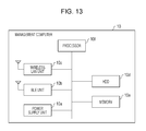
- FIG. 13 is a diagram illustrating an example of a hardware configuration of the management computer 10 .
- the management computer 10 includes a power supply unit 10 a, a BLE unit 10 b, a wireless LAN unit 10 c, a hard disk drive (HDD) 10 d, a memory 10 e, and a processor 10 f.
- a power supply unit 10 a the management computer 10 includes a power supply unit 10 a, a BLE unit 10 b, a wireless LAN unit 10 c, a hard disk drive (HDD) 10 d, a memory 10 e, and a processor 10 f.
- HDD hard disk drive
- the power supply unit 10 a controls a power supply of the management computer 10 .
- the BLE unit 10 b executes transmission control of a BLE beacon.
- the wireless LAN unit 10 c is coupled to a wireless LAN via the access point 2 and executes transmission and reception of data.
- the HDD 10 d is an example of a storage device which stores a program, data, and the like.
- An example of the memory 10 e is a random access memory (RAM) such as a synchronous dynamic random access memory (SDRAM), a read only memory (ROM), a flash memory, or the like.
- An example of the processor 10 f is a central processing unit (CPU), a digital signal processor (DSP), a field programmable gate array (FPGA), a programmable logic device (PLD), or the like.
- the management computer 10 operates as an information processing device which executes a reconnection method by reading and executing a program. That is, the management computer 10 executes a program which executes the same function as the pattern generating unit 16 , the delivering unit 17 , the monitoring unit 18 , and the instruction notification unit 19 . As a result, the management computer 10 is able to execute a process which executes the same function as the pattern generating unit 16 , the delivering unit 17 , the monitoring unit 18 , and the instruction notification unit 19 .
- a program according to the embodiment is not limited to being executed by the management computer 10 .
- the embodiment may be applied in the same manner.
- This program may be distributed via a network such as the Internet.
- the program is recorded in a computer readable recording medium such as a hard disk, a flexible disk (FD), a CD-ROM, a magneto-optical disk (MO), a digital versatile disc (DVD) and can be executed by a computer reading from the recording medium.
- a computer readable recording medium such as a hard disk, a flexible disk (FD), a CD-ROM, a magneto-optical disk (MO), a digital versatile disc (DVD) and can be executed by a computer reading from the recording medium.
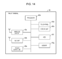
- FIG. 14 is a diagram illustrating an example of a hardware configuration of the tablet terminal 40 .
- the tablet terminal 40 includes a power supply unit 40 a, a BLE unit 40 b, a wireless LAN unit 40 c, a touch panel 40 d, a display unit 40 e, an HDD 40 f, a memory 40 g, and a processor 40 h.
- the power supply unit 40 a controls a power supply of the tablet terminal 40 .
- the BLE unit 40 b executes reception control of a BLE beacon.
- the wireless LAN unit 40 c is coupled to a wireless LAN via the access point 2 and executes transmission and reception of data.
- the touch panel 40 d is an input unit which is overlapped with the display unit 40 e and accepts user operation, and outputs an operated position (coordinate) on the processor 40 h.
- the touch panel 40 d may adopt various methods such as a capacitive method and an electromagnetic induction method.
- the display unit 40 e is an example of a display unit which displays various kinds of information.
- the HDD 40 f is an example of a storage device which stores a program, data, and the like.
- An example of the memory 40 g is a RAM such as an SDRAM and the like, a ROM, a flash memory, or the like.
- An example of the processor 40 h is a CPU, a DSP, an FPGA, a PLD, or the like.
- the tablet terminal 40 operates as an information processing device which executes a reconnection method by reading and executing a program. That is, the tablet terminal 40 executes a program which executes the same function as the display controller 47 , the receiver 48 , and the reconnection unit 49 . As a result, the tablet terminal 40 is able to execute a process which executes the same function as the display controller 47 , the receiver 48 , and the reconnection unit 49 .
- a program according to the embodiment is not limited to being executed by the tablet terminal 40 . For example, even in a case where another computer or another server executes a program or a case where the computer and the server execute a program in cooperation with each other, the embodiment may be applied in the same manner.
- This program may be distributed via a network such as the Internet.
- the program is recorded in a computer readable recording medium such as a hard disk, a flexible disk (FD), a CD-ROM, an MO, and a DVD and can be executed by a computer reading from the recording medium.
- a computer readable recording medium such as a hard disk, a flexible disk (FD), a CD-ROM, an MO, and a DVD and can be executed by a computer reading from the recording medium.
- each of components of each of devices illustrated in the drawing is functionally conceptual and is not desirable to be physically configured as illustrated in the drawing.
- specific forms of distribution and integration of each of the devices are not limited to those illustrated in the drawings. That is, all or a part thereof may be configured by being functionally or physically distributed and integrated as arbitrary units according to various loads and use situations.
- all or an arbitrary part of each of processing functions performed in each of the devices may be realized by a CPU and a program analyzed and executed by the CPU, or may be realized as hardware by wired logic.
Landscapes
- Engineering & Computer Science (AREA)
- Computer Networks & Wireless Communication (AREA)
- Signal Processing (AREA)
- Computer Security & Cryptography (AREA)
- Mobile Radio Communication Systems (AREA)
Abstract
Description
- This application is based upon and claims the benefit of priority of the prior Japanese Patent Application No. 2016-194718, filed on Sep. 30, 2016, the entire contents of which are incorporated herein by reference.
- The embodiments discussed herein are related to apparatus and method to control reconnection of a terminal device to a wireless network via another wireless network.
- According to a promotion of information and communication technology (ICT) education by government policy, for elementary and junior high schools all over the country, one tablet computer (hereinafter, may be referred to as “tablet”) per 3.6 students is deployed by the year 2017 and one per one student is deployed by the year 2020, and an achievement rate of 100% in maintenance of a wireless local area network (LAN) is planned.
- In this way, although ICT education has been gradually processed at each of schools, even now, there are schools which provide classes with a digital textbook by deploying an electronic blackboard, a wireless LAN access point (hereinafter, may be referred to as “AP”), a tablet for teacher, and a tablet for student in each of classrooms. In recent years, a technology in which when a terminal device such as a tablet or the like is coupled to another terminal device via a wireless LAN and disconnection from the wireless LAN is detected, a user performs a connection procedure with a wired LAN is known.
- Japanese Laid-open Patent Publication No. 2005-175814 is an example of the related art.
- According to an aspect of the invention, an apparatus obtains connection status information of each of terminal devices coupled to a first wireless network via an access point, from the access point. The apparatus detects a disconnected device which is a terminal device whose communication with the access point is disconnected, with reference to the connection status information, and notifies, via a second wireless network, the disconnected device of a reconnection instruction for instructing the disconnected device to reconnect to the first wireless network by accessing the access point.
- The object and advantages of the invention will be realized and attained by means of the elements and combinations particularly pointed out in the claims.
- It is to be understood that both the foregoing general description and the following detailed description are exemplary and explanatory and are not restrictive of the invention, as claimed.
-
FIG. 1 is a diagram illustrating an example of an overall configuration of a system, according to an embodiment; -
FIG. 2 is a diagram illustrating an example of a functional configuration of each of devices, according to an embodiment; -
FIG. 3 is a diagram illustrating an example of information stored in a beacon pattern database (DB), according to an embodiment; -
FIG. 4 is a diagram illustrating an example of information stored in a connection status DB, according to an embodiment; -
FIG. 5 is a diagram illustrating an example of automatic recovery, according to an embodiment; -
FIG. 6 is a diagram illustrating an example of an operational flowchart for a process of a management computer, according to an embodiment; -
FIG. 7 is a diagram illustrating an example of an operational flowchart for a process of a tablet terminal, according to an embodiment; -
FIG. 8 is a diagram illustrating an example of automatic recovery, according to an embodiment; -
FIG. 9 is a diagram illustrating an example of a functional configuration of each of devices, according to an embodiment; -
FIG. 10 is a diagram illustrating an example of information stored in an address information DB, according to an embodiment; -
FIG. 11 is a diagram illustrating an example of an operational flowchart for a process of a management computer, according to an embodiment; -
FIG. 12 is a diagram illustrating an example of an operational flowchart for a process of a tablet terminal, according to an embodiment; -
FIG. 13 is a diagram illustrating an example of a hardware configuration of a management computer, according to an embodiment; and -
FIG. 14 is a diagram illustrating an example of a hardware configuration of a tablet terminal, according to an embodiment. - Since elementary school students generally do not have high information Technology (IT) literacy, it is difficult to reconnect terminal devices disconnected from a wireless network to a wired network or a wireless network. For this reason, since a teacher manually restores the terminal, the teacher stops the class and restores the terminal device and a progress of the class is hindered every time disconnection of the terminal device occurs. In addition, in a case where the teacher's IT literacy is low, a stop time of the class will be even longer.
- It is also conceivable that a tablet terminal has a function of constantly monitoring communication with AP, and a function of executing restarting of an operating system (OS) of the tablet and executing AP reconnection when detecting disconnection. However, since tablet terminals are equipped with processors with lower performance than general personal computers, a screen display or the like is delayed when these functions are included.
- It is preferable to automatically reconnect a terminal device disconnected from a wireless network, with the wireless network.
- Hereinafter, examples of a monitoring device, a reconnection method, and a reconnection program disclosed in the present application will be described in detail with reference to drawings. The embodiment is not limited by this example. In addition, each of the examples can be appropriately combined within a range without contradiction.
- Overall Configuration Example
-
FIG. 1 is a diagram illustrating an overall configuration example of a system according to Example 1. In Example 1, as an example, a school class or the like is assumed. For example, a wireless LAN is built in a classroom, tablet terminals are distributed to each student and teacher, and a class is held by displaying information such as a textbook on the tablet terminals by using the wireless LAN. -
FIG. 1 illustrates aclassroom 1 and aserver 120 installed outside theclassroom 1. In theclassroom 1, a wireless LAN such as a Wireless-Fidelity (Wi-Fi)® is built and theclassroom 1 includes anaccess point 2, amanagement computer 10, atablet terminal 30 for teacher,tablet terminals electronic blackboard projector 100, and anelectronic pen 110. - The
access point 2 is an example of a device which connects each of tablet terminals in theclassroom 1 to a wireless LAN and connects theexternal server 120 to the wireless LAN in theclassroom 1, and is generally a computer such as a router, a station, for example. - The
tablet terminal 30 for teacher and thetablet terminals - In addition, these tablet terminals are coupled to a wireless LAN via the
access point 2 and are coupled to each other so as to communicate with each other. Further, each of the tablet terminals is coupled to theexternal server 120 via theaccess point 2. Each of the tablet terminals displays textbook data delivered from themanagement computer 10 or theserver 120. Here, a class is held using textbook data instead of an ordinary textbook. - The
management computer 10 is an example of a computer such as a monitoring device and is coupled to theaccess point 2 via a wireless LAN or a wired line. Themanagement computer 10 obtains textbook data from theserver 120 via theaccess point 2 and delivers the data to each of the tablet terminals coupled to a wireless LAN via theaccess point 2. - For example, the
electronic blackboard projector 100 is coupled to themanagement computer 10 via a wired line such as a High-Definition Multimedia Interface (HDMI)®. Theelectronic blackboard projector 100 projects various images and videos input from themanagement computer 10 on a screen. In addition, theelectronic blackboard projector 100 is coupled to theelectronic pen 110 via infrared rays or the like and projects operation information by theelectronic pen 110 on the screen together with various images and videos input from themanagement computer 10. - The
server 120 is an example of an external server which is coupled to theaccess point 2 and holds textbook data. Upon receiving a request for data acquisition from each of the tablet terminals or themanagement computer 10, theserver 120 transmits the textbook data to a request destination via theaccess point 2. - In this way, in a state in which the
tablet terminal 30 for teacher and thetablet terminals access point 2, themanagement computer 10 obtains, from theaccess point 2, connection status of each of the tablet terminals coupled to a wireless LAN via theaccess point 2. With reference to the connection status, themanagement computer 10 detects a tablet terminal (hereinafter, sometimes described as “disconnected tablet”) disconnected from communication with theaccess point 2. Thereafter, themanagement computer 10 notifies, by using a Bluetooth® Low Energy (BLE) beacon, the disconnected tablet being disconnected from a wireless LAN of a reconnection instruction for instructing the disconnected tablet to reconnect with a wireless LAN by accessing theaccess point 2. - Therefore, upon detecting a tablet for student disconnected from a wireless LAN in a classroom during a class, the
management computer 10 transmits the reconnection instruction for reconnection with a wireless LAN, by using a BLE beacon. As a result, the tablet terminal disconnected from a wireless LAN may automatically reconnect with a wireless LAN without a teacher or a student performing recovery operation. - Functional Configuration
- Next, functional configurations of devices illustrated in
FIG. 1 will be described. Here, functional configurations of themanagement computer 10 and each of the tablet terminals, which have functions different from a general device, will be described. Since each of the tablet terminals has the same configuration, thetablet terminal 40 will be described as an example. - Functional Configuration of
Management Computer 10 -
FIG. 2 is a functional block diagram illustrating a functional configuration of each of devices according to Example 1. As illustrated inFIG. 2 , themanagement computer 10 includes acommunication unit 11, astorage unit 12, and acontroller 15. - The
communication unit 11 is a processing unit which controls various communications such as a wireless communication or a wire communication. For example, thecommunication unit 11 is coupled to a wireless LAN via theaccess point 2, transmits information to each of the tablet terminals in a wireless LAN, and receives various kinds of information from each of the tablet terminals. For example, thecommunication unit 11 receives connection status from theaccess point 2 and transmits textbook data to each of the tablet terminals. In addition, thecommunication unit 11 executes transmission control of a BLE beacon or the like. - The
storage unit 12 is a storage device which stores a program executed by thecontroller 15 or various kinds of data and is, for example, a memory or a hard disk. Thestorage unit 12 stores abeacon pattern DB 13 or aconnection status DB 14. - The
beacon pattern DB 13 is a database storing a beacon pattern which is a combination of channels of transmission frequencies of a BLE beacon. For example, thebeacon pattern DB 13 is a combination of advertising channels used in the BLE beacon and stores identification information used for identifying a tablet terminal of each student. -
FIG. 3 is a diagram illustrating an example of information stored in thebeacon pattern DB 13. As illustrated inFIG. 3 , thebeacon pattern DB 13 stores “tablet terminal”, “media access control (MAC) address”, and “transmission channel (first time, second time, and third time)” in association with each other. “tablet terminal” is a name of a tablet terminal used by a student, and “MAC address” is a MAC address of the tablet terminal for each student. “transmission channel” is channel information of an advertising channel, and “first time”, “second time”, and “third time” are advertising channels used by a BLE beacon. - In the example in
FIG. 3 , in a case of transmitting an instruction to a tablet terminal of a student A of which a MAC address is “A1:B2:C3:F3:E2:D1”, “37 ch” is used for the first time, “37 ch” is used for the second time, and “37 ch” is used for the third time. In this way, by a combination of advertising channels (37 ch, 38 ch, and 39 ch), each of the tablet terminals is identified. The combination of advertising channels may be changed for each of classes. In addition, inFIG. 3 , a tablet terminal for teacher is excluded from a management target, but the tablet terminal for teacher may be included in the management target in the same manner as a tablet terminal for student. - The
connection status DB 14 is a database which stores connection status of each of the tablet terminals coupled to a wireless LAN. Information stored here may be collected by theaccess point 2. -
FIG. 4 is a diagram illustrating an example of information stored in theconnection status DB 14. As illustrated inFIG. 4 , theconnection status DB 14 stores “tablet terminal”, “MAC address”, “status”, “disconnection time”, and “disconnection reason” in association with each other. Here, “tablet terminal” is a name of a tablet terminal used by a student, and “MAC address” is a MAC address of the tablet terminal for each student. “tablet terminal” and “MAC address” may be preset. - “status” indicates connection status and stores “connecting” or “unconnected”. “disconnection time” is disconnected time. “disconnection reason” indicates whether or not a tablet terminal is disconnected during a class, and is set at “unexpected disconnection” in a case where the tablet terminal is disconnected during the class. “disconnection reason” may be determined by the
access point 2 or themanagement computer 10. -
FIG. 4 illustrates that in a tablet terminal of a student C of which a MAC address is “A1:B2:C3:F3:E2:D3”, “unexpected disconnection” occurs at “9:45” and the other tablet terminals of the other students are normally connected. - The
controller 15 is a processing unit which manages whole of themanagement computer 10 and is, for example, a processor or the like. Thecontroller 15 includes apattern generating unit 16, a deliveringunit 17, amonitoring unit 18, and aninstruction notification unit 19. Thepattern generating unit 16, the deliveringunit 17, themonitoring unit 18, and theinstruction notification unit 19 are an example of an electronic circuit included in a processor or the like or an example of a process executed by the processor. - The
pattern generating unit 16 is a processing unit which generates a combination of advertising channels for identifying each of the tablet terminals. For example, thepattern generating unit 16 generates a beacon pattern illustrated inFIG. 3 , and saves the beacon pattern in thebeacon pattern DB 13 at a class start time. In addition, thepattern generating unit 16 also may delete information stored in thebeacon pattern DB 13 at a class end time. The class start time or the class end time may be preset. In addition, as a generating method, it is possible to adopt a BLE random address setting and the like, and to arbitrarily change a combination of channels or the number of times of transmission, depending on the number of tablet terminals. - The delivering
unit 17 is a processing unit which delivers the beacon pattern generated by thepattern generating unit 16 to each of the tablet terminals via a wireless LAN. For example, when a beacon pattern is saved in thebeacon pattern DB 13, the deliveringunit 17 reads the beacon pattern from thebeacon pattern DB 13 and transmits the beacon pattern, via theaccess point 2, to each of the tablet terminals by using “MAC address” stored in advance in theconnection status DB 14. - The
monitoring unit 18 is a processing unit which monitors connection status of a tablet terminal to a wireless LAN for each student. For example, themonitoring unit 18 obtains connection status (status, disconnection time, and the like) from theaccess point 2, and monitors whether or not unexpected disconnection occurs. For example, themonitoring unit 18 regularly obtains connection status from theaccess point 2 and saves the obtained connection status in theconnection status DB 14. Then, in a case of detecting status “unconnected” during a class, themonitoring unit 18 sets “unexpected disconnection” to “disconnection reason” for a tablet terminal from which status “unconnected” has been detected. - The
instruction notification unit 19 is a processing unit which notifies a tablet terminal to which “unexpected disconnection” is set by themonitoring unit 18, by using BLE different from a wireless LAN, of an instruction for reconnection to a wireless LAN by accessing theaccess point 2. For example, theinstruction notification unit 19 specifies a combination of transmission channels corresponding to a tablet terminal for student in a disconnected state, from thebeacon pattern DB 13, and broadcasts an instruction for reconnection by using the specified combination. - For example, upon detecting that “unexpected disconnection” is set to a tablet terminal of the student C with reference to the
connection status DB 14, theinstruction notification unit 19 obtains disconnection time “9:45” from theconnection status DB 14. Next, theinstruction notification unit 19 obtains transmission channels (37 ch, 37 ch, and 39 ch) of the tablet terminal of the student C in a disconnected state, from thebeacon pattern DB 13. Then, theinstruction notification unit 19 broadcasts an advertised packet including time information “9:45” which is disconnection time, as a BLE beacon via 37 ch. After a predetermined time (for example, 30 seconds), theinstruction notification unit 19 broadcasts an advertised packet including time information “9:45” as a BLE beacon via 37 ch. Further, after a predetermined time (for example, 30 seconds), theinstruction notification unit 19 broadcasts an advertised packet including time information “9:45” as a BLE beacon via 39 ch. - That is, by notifying a BLE beacon three times for one disconnection detection, it is possible to notify disconnection time to the tablet terminal of the student C in a disconnected state. The BLE beacon may include a reconnection instruction, a reconnection command, or the like. The predetermined time may be arbitrarily changed.
- In this way, by broadcasting packet data with a combination of three frequency channels, it is possible to identify a tablet terminal for student. In addition, since Bluetooth® device address (BD address), which may be an attack target when acquired by a third party, is not included in the beacon, security is high and risk of becoming the attack target of the third party becomes also small.
- In addition, in a case where a disconnected tablet terminal is detected and nothing is registered as a disconnection reason, that is, “unexpected disconnection” is not registered as a disconnection reason, the
instruction notification unit 19 determines that a class is ended and deletes a beacon pattern stored in thebeacon pattern DB 13. - Functional Configuration of
Tablet Terminal 40 - As illustrated in
FIG. 2 , thetablet terminal 40 includes acommunication unit 41, adisplay unit 42, astorage unit 43, and acontroller 46. - The
communication unit 41 is a processing unit which is coupled to a wireless LAN via theaccess point 2 and controls communication with another tablet terminal, themanagement computer 10, theserver 120, and the like. For example, thecommunication unit 41 receives textbook data from themanagement computer 10 via theaccess point 2. - In addition, the
communication unit 41 receives a BLE beacon broadcasted from themanagement computer 10. For example, thecommunication unit 41 receives an advertised packet including time information and the like from themanagement computer 10 without going through theaccess point 2. - The
display unit 42 is a touch panel display which displays each piece of information and accepts operation of a student or the like. For example, thedisplay unit 42 displays textbook data and accepts page turning operation, answer operation to a problem, or the like. - The
storage unit 43 is a storage device which stores a program executed by thecontroller 46 or various kinds of data and is, for example, a memory or a hard disk. Thestorage unit 43 stores a beacon pattern DB 44 and adisconnection time DB 45. - The beacon pattern DB 44 is a database which stores a beacon pattern which is a combination of transmission frequency channels of a BLE beacon. For example, the beacon pattern DB 44 stores a beacon pattern delivered from the
management computer 10. The stored information is the same as inFIG. 3 , and a detailed description thereof will be omitted. - The
disconnection time DB 45 is a database which stores a time at which thetablet terminal 40 is disconnected from a wireless LAN. For example, thedisconnection time DB 45 stores disconnection time “9:45” and the like. Here, the stored disconnection time is the latest disconnection time and is updated by thecontroller 46. - The
controller 46 is a processing unit which manages theoverall tablet terminal 40 and is, for example, a processor or the like. Thecontroller 46 includes a display controller 47, a receiver 48, and areconnection unit 49. The display controller 47, the receiver 48, and thereconnection unit 49 are an example of an electronic circuit included in a processor or the like or an example of a process executed by the processor. - Upon detecting a tablet disconnected from a wireless LAN, the
controller 46 determines whether or not disconnected time is in a time zone designated in advance such as a time zone in which a class is ended. In a case where the disconnected time is not in the time zone designated in advance, thecontroller 46 makes a determination of unexpected disconnection and saves the disconnection time in thedisconnection time DB 45. On the other hand, in a case where the disconnected time is in the time zone designated in advance, thecontroller 46 makes a determination of a class being ended and deletes information stored in the beacon pattern DB 44. - The display controller 47 is a processing unit which executes an information display or touch panel operation. For example, the display controller 47 displays textbook data received from the
management computer 10 on thedisplay unit 42. In addition, the display controller 47 accepts touch panel operation via thedisplay unit 42 and executes a process corresponding to the accepted touch panel operation. For example, the display controller 47 executes page turning when swipe operation is accepted and executes an enlarged display when receiving double click operation. - The receiver 48 is a processing unit which receives a beacon pattern delivered from the
management computer 10. For example, the receiver 48 receives a beacon pattern from themanagement computer 10 via theaccess point 2 and saves the beacon pattern in the beacon pattern DB 44. - The
reconnection unit 49 is a processing unit which executes reconnection to a wireless LAN according to a reconnection instruction from themanagement computer 10. For example, thereconnection unit 49 receives a BLE beacon with a beacon pattern assigned to thetablet terminal 40 and executes reconnection in a case where disconnection time notified with the received BLE beacon matches with disconnection time stored in thedisconnection time DB 45. - For example, a case where the
tablet terminal 40 is a tablet terminal of the student C will be described. Thereconnection unit 49 specifies that a beacon pattern assigned to thetablet terminal 40 is 37 ch, 37 ch, and 39 ch with reference to the beacon pattern DB 44. Thereafter, thereconnection unit 49 receives an advertised packet of a BLE beacon broadcasted from themanagement computer 10 via 37 ch, subsequently receives an advertised packet of a BLE beacon broadcasted via 37 ch, and lastly receives an advertised packet of a BLE beacon broadcasted via 39 ch. - Then, since the respective channels used by the
management computer 10 are equal to a beacon pattern (37 ch, 37 ch, and 39 ch) of thetablet terminal 40, thereconnection unit 49 determines that the advertised packets are addressed to thetablet terminal 40. Thereconnection unit 49 extracts time information from each of the received three advertised packets, and restarts thetablet terminal 40 and reconnects to a wireless LAN in a case where each piece of time information is equal to disconnection time (9:45) stored in thedisconnection time DB 45. A reconnection process is not limited to rebooting but can also include executing a command and the like designated in advance. - Next, a specific example of reconnection to a wireless LAN described in Example 1 will be described.
FIG. 5 is a diagram for explaining automatic recovery according to Example 1. As illustrated inFIG. 5 , in theclassroom 1, a class is held by thetablet terminal 30 for teacher, thetablet terminals management computer 10 being coupled to each other by a wireless LAN via theaccess point 2. In this state, it is assumed that thetablet terminal 40 is disconnected from theaccess point 2. - The
management computer 10 obtains connection status from theaccess point 2 and detects unexpected disconnection of the tablet terminal 40 (S1). At this time, themanagement computer 10 obtains disconnection time from the connection status. - Next, the
management computer 10 specifies a beacon pattern assigned to thetablet terminal 40 from thebeacon pattern DB 13 and broadcasts an advertised packet including the disconnection time by using the specified beacon pattern (S2). - Thereafter, each of the
tablet terminals tablet terminal 40 among thetablet terminals tablet terminal 40, thetablet terminal 40 determines that the advertised packets are addressed to thetablet terminal 40. When disconnection time included in each of the advertised packets matches with disconnection time stored in thedisconnection time DB 45 of thetablet terminal 40, thetablet terminal 40 executes restarting (S3). - In this way, the
management computer 10 executes automatic connection of a tablet terminal disconnected from a wireless LAN via a wireless network different from a wireless LAN. - Flow of Process
- Next, a process of each of devices will be described. Here, a process of the
management computer 10 and a process of a disconnected tablet terminal will be described. As an example, a disconnected tablet terminal is thetablet terminal 40. - Process of
Management Computer 10 -
FIG. 6 is a flowchart illustrating a flow of a process of themanagement computer 10 according to Example 1. As illustrated inFIG. 6 , when connection of all of tablet terminals is completed (Yes in S101), thepattern generating unit 16 of themanagement computer 10 generates a beacon pattern (S102). Thereafter, the deliveringunit 17 delivers the beacon pattern to each of the tablet terminals via the access point 2 (S103). In the case, thepattern generating unit 16 may receive a notification of connection completion from theaccess point 2 or may also determine the connection completion from connection status obtained from theaccess point 2. - Next, upon obtaining the connection status from the access point 2 (S104), the
monitoring unit 18 determines whether or not an unconnected tablet terminal exists (S105). Here, themonitoring unit 18 stores a disconnection reason and the like in theconnection status DB 14. In a case where an unconnected tablet terminal does not exist (No in S105), themonitoring unit 18 repeats S104 and the following steps. - In a case where the
monitoring unit 18 determines that an unconnected tablet terminal exists (Yes in S105), theinstruction notification unit 19 obtains a disconnection reason and disconnection time (S106). The disconnection reason may be determined also by themanagement computer 10 and theaccess point 2 by using the similar method. - Thereafter, in a case where the disconnection reason is “unexpected disconnection” (Yes in S107), the
instruction notification unit 19 specifies a beacon pattern corresponding to a tablet terminal of “unexpected disconnection” from the beacon pattern DB 13 (S108). Next, theinstruction notification unit 19 transmits an advertised packet including the disconnection time with the corresponding beacon pattern as a BLE beacon (S109). Thereafter, S104 and the following steps are repeated. - On the other hand, in a case where the disconnection reason is not “unexpected disconnection” (No in S107), the
instruction notification unit 19 determines that a class is ended and deletes a beacon pattern stored in the beacon pattern DB 13 (S110). - Process of
Tablet Terminal 40 -
FIG. 7 is a flowchart illustrating a flow of a process of thetablet terminal 40 according to Example 1. As illustrated inFIG. 7 , after connection to a wireless LAN is completed (Yes in S201), the receiver 48 of thetablet terminal 40 receives a beacon pattern by a wireless LAN via theaccess point 2 and saves the beacon pattern in the beacon pattern DB 44 (S202). - Thereafter, upon detecting a tablet disconnected from a wireless LAN (Yes in S203), the
controller 46 determines whether or not a disconnection reason is unexpected disconnection (S204). Here, in a case where it is determined that the disconnection reason is unexpected disconnection (Yes in S204), thecontroller 46 saves the disconnection time in the disconnection time DB 45 (S205). - Thereafter, in a case where a BLE beacon is received (Yes in S206) and it is determined that the BLE beacon is addressed to the
tablet terminal 40, based on the beacon pattern (Yes in S207), thereconnection unit 49 extracts disconnection time from each of advertised packets transmitted as a BLE beacon (S208). - In a case where the extracted disconnection time matches with disconnection time stored in the disconnection time DB 45 (Yes in S209), the
reconnection unit 49 executes a reconnecting process (S210) and reconnects to a wireless LAN (S211). Thereafter, S203 and the following steps are repeated. - On the other hand, in a case where the extracted disconnection time does not match with disconnection time stored in the disconnection time DB 45 (No in S209), the flow returns to S206 and the
reconnection unit 49 waits for receiving a BLE beacon. In a case where it is determined that the disconnection reason is not unexpected disconnection in S204 (No in S204), thecontroller 46 deletes a beacon pattern from the beacon pattern DB 44 (S212). - Effect
- As described above, even in a case where a low-performance tablet terminal is used, the
management computer 10 may be automatically recovered from a trouble of a wireless LAN connection without going through a person. As a result, it is possible to provide an environment which minimizes class stop time. - In addition, in a case where a wireless LAN disconnection occurs and a BLE beacon which each of tablet terminals for students receives is addressed to the tablet terminal for student, pieces of information about disconnection time are compared and wireless LAN recovery operation is performed when the pieces of information about disconnection time match with each other. Therefore, since the tablet terminal for student receives the BLE beacon only when disconnected from a wireless LAN and performs wireless LAN recovery operation only when pieces of information about disconnection time match with each other, it is possible to realize more securely remote recovery. In addition, since only disconnection time is transmitted and leakage of address information of a tablet terminal may be suppressed even if the disconnection time leaks to an outside, the
management computer 10 may minimize damage caused by a malicious third party. - In Example 1, an example in which a reconnection instruction is notified to a tablet terminal in a state of the tablet terminal being disconnected by using a beacon pattern and broadcasting is described, but the example is not limited thereto. For example, it is also possible to directly connect to a tablet terminal during disconnection and to execute a reconnecting process by using a Bluetooth® (hereinafter, may be referred to as “BT”). Therefore, in Example 2, an example in which the
management computer 10 is directly connected to a tablet terminal during disconnection and causes the tablet terminal to execute a reconnecting process and to automatically recover the connection to a wireless LAN will be described. - Description of Automatic Recovery of Example 2
-
FIG. 8 is a diagram for explaining automatic recovery according to Example 2. An overall configuration of a system illustrated inFIG. 8 is the same as that of Example 1. - As illustrated in
FIG. 8 , in a state in which a class is held using a wireless LAN in theclassroom 1, themanagement computer 10 obtains connection status from theaccess point 2 and detects unexpected disconnection of the tablet terminal 40 (S11). At this time, themanagement computer 10 obtains disconnection time from the connection status. - Next, the
management computer 10 directly connects to thetablet terminal 40 during the disconnection from a wireless LAN by using BT, and issues a restarting command to the tablet terminal 40 (S12). As a result, thetablet terminal 40 is able to automatically reconnect to a wireless LAN (S13). - Functional Configuration
- Next, functional configurations of devices illustrated
FIG. 8 will be described. Here, among functional configurations of themanagement computer 10 and thetablet terminal 40, functions different from those of Example 1 will be described. The same reference numerals are given to the same functions, but different processes will be separately described even if the same reference numerals are given. - Functional Configuration of
Management Computer 10 -
FIG. 9 is a functional block diagram illustrating a functional configuration of each of devices according to Example 2. As illustrated inFIG. 9 , themanagement computer 10 includes thecommunication unit 11, thestorage unit 12, and thecontroller 15. - The
storage unit 12 is a storage device which stores a program executed by thecontroller 15 or various kinds of data and is, for example, a memory or a hard disk. Thestorage unit 12 stores theconnection status DB 14 and anaddress information DB 20. - The
address information DB 20 is address information used for BT connection and stores a Bluetooth® Device address (BD address) of each of the tablet terminals. Information stored therein is set and changed by an administrator or the like. -
FIG. 10 is a diagram illustrating an example of information stored in theaddress information DB 20. As illustrated inFIG. 10 , theaddress information DB 20 stores “tablet terminal”, “MAC address”, and “BD address” in association with each other. “tablet terminal” is a name of a tablet terminal used by a student, and “MAC address” is a MAC address of the tablet terminal for each student. “BD address” is address information used for BT connection. - In the example in
FIG. 10 , a MAC address of a tablet terminal of the student C is “A1:B2:C3:F3:E2:D3” and a BD address thereof is “B1:C2:D3:G3:F2:E3”. - The
controller 15 is a processing unit which manages the whole of themanagement computer 10 and is, for example, a processor or the like. Thecontroller 15 includes amonitoring unit 21, an establishingunit 22, and areconnection unit 23. Themonitoring unit 21, the establishingunit 22, and thereconnection unit 23 are an example of an electronic circuit included in a processor or the like or an example of a process executed by the processor. - The
monitoring unit 21 executes the same process as themonitoring unit 18 described Example 1. For example, themonitoring unit 21 obtains connection status (status and disconnection time) from theaccess point 2 and monitors whether or not unexpected disconnection occurs. For example, themonitoring unit 21 regularly obtains connection status from theaccess point 2 and saves the obtained connection status in theconnection status DB 14. Then, in a case of detecting status “unconnected” during a class, themonitoring unit 21 sets “unexpected disconnection” to “disconnection reason” of a tablet terminal corresponding to “unconnected”. - The establishing
unit 22 is a processing unit which establishes BT connection with a tablet terminal being disconnected from wireless LAN. For example, upon detecting, with reference to theconnection status DB 14, a tablet terminal for which “unexpected disconnection” is registered, the establishingunit 22 specifies a BD address of the corresponding tablet terminal from theaddress information DB 20. The establishingunit 22 executes BT connection by designating the specified BD address and establishes BT connection with the tablet terminal being disconnected from wireless LAN. - For example, upon detecting “unexpected disconnection” of a tablet terminal of the student C with reference to the
connection status DB 14, the establishingunit 22 obtains a BD address “B1:C2:D3:G3:F2:E3” of the tablet terminal of the student C from theaddress information DB 20. The establishingunit 22 designates the BD address “B1:C2:D3:G3:F2:E3” to transmit a BT connection request. Thereafter, upon receiving a connection response, the establishingunit 22 establishes BT connection with a tablet terminal of the student C to which the BD address “B1:C2:D3:G3:F2:E3” is set. - The
reconnection unit 23 is a processing unit which causes the tablet terminal disconnected from a wireless LAN to execute a reconnecting process. For example, thereconnection unit 23 issues start operation or a command of the reconnecting process by BT communication to the tablet terminal in which BT connection is established by the establishingunit 22. In the above example, thereconnection unit 23 issues a command or the like of restarting by BT connection to the tablet terminal of the student C in which BT connection is established. - When the tablet terminal of the student C is restarted, the
reconnection unit 23 automatically establishes BT connection with the tablet terminal of the student C. Then, thereconnection unit 23 determines that reconnection to a wireless LAN is completed and automatically disconnects BT connection. - Functional Configuration of
Tablet Terminal 40 - As illustrated in
FIG. 9 , thetablet terminal 40 includes thecommunication unit 41, thedisplay unit 42, thestorage unit 43, and thecontroller 46. - A difference from
FIG. 2 described in Example 1 is that thestorage unit 43 does not store the beacon pattern DB 44. In addition, since thereconnection unit 49 of thecontroller 46 includes a process different from Example 1, the process will be described. - The
reconnection unit 49 is a processing unit which establishes BT connection with themanagement computer 10 and receives an instruction for a reconnecting process via the BT connection, in contrast with Example 1. For example, in a case where “unexpected disconnection” is detected by thecontroller 46, thereconnection unit 49 moves to a waiting state for BT connection. Thereafter, upon receiving a connection request by BT from themanagement computer 10, thereconnection unit 49 transmits a connection response to themanagement computer 10 by using BT. - In this way, in a state in which the
reconnection unit 49 may not be connected to a wireless LAN, thereconnection unit 49 establishes BT connection with themanagement computer 10. Thereafter, thereconnection unit 49 receives a restarting command or the like from themanagement computer 10 via BT connection. Thetablet terminal 40 executes restarting by receiving a restarting command from themanagement computer 10. Restarting may be performed remotely by themanagement computer 10 or performed locally by themanagement computer 10. - Thereafter, when the
tablet terminal 40 is restarted, thereconnection unit 49 automatically establishes BT connection with themanagement computer 10. Thereafter, when thereconnection unit 49 determines that reconnection to a wireless LAN is completed, thereconnection unit 49 automatically disconnects BT connection. - Flow of Process
- Next, a process of each of devices according to Example 2 will be described. Here, a process of the
management computer 10 and a process of a tablet terminal will be described. As an example, a disconnected tablet terminal is thetablet terminal 40. - Process of
Management Computer 10 -
FIG. 11 is a flowchart illustrating a flow of a process of themanagement computer 10 according to Example 2. As illustrated inFIG. 11 , when connection of all of the tablet terminals is completed (Yes in S301) and connection status is obtained from the access point 2 (S302), themonitoring unit 21 of themanagement computer 10 determines whether or not an unconnected tablet terminal exists (S303). Here, in a case where an unconnected tablet terminal does not exist (No in S303), themonitoring unit 21 repeats S302 and the following steps. - In a case where the
monitoring unit 21 determines that an unconnected tablet terminal exists (Yes in S303), the establishingunit 22 obtains a disconnection reason and disconnection time (S304). - Thereafter, in a case where the disconnection reason is “unexpected disconnection” (Yes in S305), the establishing
unit 22 specifies address information (BD address) of a tablet terminal being disconnected corresponding to “unexpected disconnection”, from the address information DB 20 (S306). - Next, the establishing
unit 22 transmits a request for BT connection by designating the specified address information (S307). Upon receiving a connection response (Yes in S308), the establishingunit 22 completes BT connection with the tablet terminal being disconnected (S309). - The
reconnection unit 23 causes, by using BT, the tablet terminal being disconnected to execute a reconnecting process (S310). In a case where connection completion of the unconnected tablet is confirmed according to the connection status afterward obtained by the monitoring unit 21 (Yes in S312), thereconnection unit 23 disconnects BT (S313). Thereafter, S302 and the following steps are repeated. - On the other hand, in a case where the unconnected tablet terminal is detected in the connection status afterward obtained by the
monitoring unit 21 and connection completion of the unconnected tablet is not confirmed (No in S312), thereconnection unit 23 returns to S310 and executes the reconnecting process to the tablet terminal being disconnected again. Thereconnection unit 23 may execute S313 without executing S311 and S312 assuming that reconnection to a wireless LAN is completed. Even in this case, since an unconnected state is detected by obtaining the next connection status, the reconnecting process may be repeatedly executed. - On the other hand, in a case where it is determined that the disconnection reason is not “unexpected disconnection” (No in S305), the process is ended.
- Process of
Tablet Terminal 40 -
FIG. 12 is a flowchart illustrating a flow of a process of thetablet terminal 40 according to Example 2. As illustrated inFIG. 12 , after connection to a wireless LAN is completed (Yes in S401), upon detecting disconnection from a wireless LAN (Yes in S402), thecontroller 46 of thetablet terminal 40 determines whether or not a disconnection reason is unexpected disconnection (S403). Here, in a case where the disconnection reason is not unexpected disconnection (No in S403), thecontroller 46 ends the process. - On the other hand, in a case where the
controller 46 determines that the disconnection reason is unexpected disconnection (Yes in S403), thereconnection unit 49 moves to a waiting state for BT connection (S404). Upon receiving a request for BT connection from the management computer 10 (Yes in S405), thereconnection unit 49 transmits a response for BT connection to the management computer 10 (S406). Then, thereconnection unit 49 completes BT connection (S407). - Thereafter, upon receiving a reconnection request via BT (Yes in S408), the
reconnection unit 49 execute the reconnecting process (S409), reconnects to a wireless LAN (S410), and disconnects BT (S411). Thereconnection unit 49 may control BT to disconnect BT after reconnection to a wireless LAN succeeds, or may control BT to disconnect BT regardless of success or failure of reconnection after restarting is completed. - Effect
- In this way, the
management computer 10 transmits a reconnection operation instruction to a tablet terminal of a student, and the tablet terminal of the student executes reconnection operation. When the tablet terminal of the student is reconnected to a wireless LAN, the tablet terminal disconnects BT connection. Therefore, since the tablet terminal of the student establishes BT connection only during a time period in which reconnection operation to a wireless LAN is being performed, it is possible to minimize power consumption. In addition, since themanagement computer 10 is directly connected to a tablet terminal being disconnected and causes the tablet terminal to execute reconnection, it is possible to improve a probability of success in reconnection. - Although the examples of the embodiment are described so far, the embodiment may be implemented in various different forms in addition to the examples described above. Therefore, different examples will be described below.
- Wireless Line
- Although a wireless LAN or BLE, a wireless LAN and BT, and the like are described as examples in the above examples, the embodiment is not limited thereto. For example, instead of BT or BLE, other non-contact communication or the like may be adopted.
- In addition, since advertising channel frequencies (37 ch, 38 ch, and 39 ch) used for the above BLE beacon are not overlapped with channel frequencies (1 ch, 6 ch, and 11 ch) used for an ordinary wireless LAN, it is possible to reduce failure due to radio wave interference. In addition, a beacon is not limited to BLE, another beacon may be adopted, and channels may also be used for other channels not used for a wireless LAN and the like.
- Tablet Terminal
- Although a tablet terminal for student is described as a target of automatic recovery in the above examples, the embodiment is not limited thereto and a tablet terminal for teacher may be a target of automatic recovery. In addition, not only a tablet terminal but also another computer such as a smartphone, a server, or the like may be a target of automatic recovery.
- Transmission Information
- Although an example in which disconnection time is transmitted by a BLE beacon is described in Example 1, it is possible to execute only a notification using a beacon pattern without transmitting disconnection time. By transmitting the disconnection time, it is possible to execute a two-step determination of a notification using the beacon pattern and a coincidence of the disconnection time, thereby improving a security level.
- Environment
- Although a wireless LAN in a classroom is described as an example in the above examples, the embodiment is not limited thereto and may apply to inside a hospital, inside a warehouse, inside a vehicle, or the like in the same manner.
- Hardware Configuration of
Management Computer 10 -
FIG. 13 is a diagram illustrating an example of a hardware configuration of themanagement computer 10. As illustrated inFIG. 13 , themanagement computer 10 includes apower supply unit 10 a, aBLE unit 10 b, awireless LAN unit 10 c, a hard disk drive (HDD) 10 d, amemory 10 e, and aprocessor 10 f. - The
power supply unit 10 a controls a power supply of themanagement computer 10. TheBLE unit 10 b executes transmission control of a BLE beacon. Thewireless LAN unit 10 c is coupled to a wireless LAN via theaccess point 2 and executes transmission and reception of data. TheHDD 10 d is an example of a storage device which stores a program, data, and the like. - An example of the
memory 10 e is a random access memory (RAM) such as a synchronous dynamic random access memory (SDRAM), a read only memory (ROM), a flash memory, or the like. An example of theprocessor 10 f is a central processing unit (CPU), a digital signal processor (DSP), a field programmable gate array (FPGA), a programmable logic device (PLD), or the like. - In addition, the
management computer 10 operates as an information processing device which executes a reconnection method by reading and executing a program. That is, themanagement computer 10 executes a program which executes the same function as thepattern generating unit 16, the deliveringunit 17, themonitoring unit 18, and theinstruction notification unit 19. As a result, themanagement computer 10 is able to execute a process which executes the same function as thepattern generating unit 16, the deliveringunit 17, themonitoring unit 18, and theinstruction notification unit 19. A program according to the embodiment is not limited to being executed by themanagement computer 10. For example, even in a case where another computer or another server executes a program or a case where the computer and the server execute a program in cooperation with each other, the embodiment may be applied in the same manner. The same applies to a program which executes the same function as each of functional units described in Example 2. - This program may be distributed via a network such as the Internet. In addition, the program is recorded in a computer readable recording medium such as a hard disk, a flexible disk (FD), a CD-ROM, a magneto-optical disk (MO), a digital versatile disc (DVD) and can be executed by a computer reading from the recording medium.
- Hardware Configuration of
Tablet Terminal 40 -
FIG. 14 is a diagram illustrating an example of a hardware configuration of thetablet terminal 40. As illustrated inFIG. 14 , thetablet terminal 40 includes apower supply unit 40 a, aBLE unit 40 b, awireless LAN unit 40 c, atouch panel 40 d, adisplay unit 40 e, anHDD 40 f, amemory 40 g, and aprocessor 40 h. - The
power supply unit 40 a controls a power supply of thetablet terminal 40. TheBLE unit 40 b executes reception control of a BLE beacon. Thewireless LAN unit 40 c is coupled to a wireless LAN via theaccess point 2 and executes transmission and reception of data. - The
touch panel 40 d is an input unit which is overlapped with thedisplay unit 40 e and accepts user operation, and outputs an operated position (coordinate) on theprocessor 40 h. Thetouch panel 40 d may adopt various methods such as a capacitive method and an electromagnetic induction method. Thedisplay unit 40 e is an example of a display unit which displays various kinds of information. - The
HDD 40 f is an example of a storage device which stores a program, data, and the like. An example of thememory 40 g is a RAM such as an SDRAM and the like, a ROM, a flash memory, or the like. An example of theprocessor 40 h is a CPU, a DSP, an FPGA, a PLD, or the like. - In addition, the
tablet terminal 40 operates as an information processing device which executes a reconnection method by reading and executing a program. That is, thetablet terminal 40 executes a program which executes the same function as the display controller 47, the receiver 48, and thereconnection unit 49. As a result, thetablet terminal 40 is able to execute a process which executes the same function as the display controller 47, the receiver 48, and thereconnection unit 49. A program according to the embodiment is not limited to being executed by thetablet terminal 40. For example, even in a case where another computer or another server executes a program or a case where the computer and the server execute a program in cooperation with each other, the embodiment may be applied in the same manner. - This program may be distributed via a network such as the Internet. In addition, the program is recorded in a computer readable recording medium such as a hard disk, a flexible disk (FD), a CD-ROM, an MO, and a DVD and can be executed by a computer reading from the recording medium.
- System
- In addition, among all processes described in the present examples, all or a part of the processes explained as being automatically performed can also be performed manually. Alternatively, all or a part of the processes described as being performed manually can be automatically performed by a known method. Further, processing procedures, control procedures, specific names, and information including various data and parameters illustrated in the document or in the drawings can be arbitrarily changed unless otherwise noted.
- In addition, each of components of each of devices illustrated in the drawing is functionally conceptual and is not desirable to be physically configured as illustrated in the drawing. In other words, specific forms of distribution and integration of each of the devices are not limited to those illustrated in the drawings. That is, all or a part thereof may be configured by being functionally or physically distributed and integrated as arbitrary units according to various loads and use situations. Further, all or an arbitrary part of each of processing functions performed in each of the devices may be realized by a CPU and a program analyzed and executed by the CPU, or may be realized as hardware by wired logic.
- All examples and conditional language recited herein are intended for pedagogical purposes to aid the reader in understanding the invention and the concepts contributed by the inventor to furthering the art, and are to be construed as being without limitation to such specifically recited examples and conditions, nor does the organization of such examples in the specification relate to a showing of the superiority and inferiority of the invention. Although the embodiments of the present invention have been described in detail, it should be understood that the various changes, substitutions, and alterations could be made hereto without departing from the spirit and scope of the invention.
Claims (6)
Applications Claiming Priority (2)
| Application Number | Priority Date | Filing Date | Title |
|---|---|---|---|
| JP2016-194718 | 2016-09-30 | ||
| JP2016194718A JP6634995B2 (en) | 2016-09-30 | 2016-09-30 | Monitoring device, reconnection method and reconnection program |
Publications (2)
| Publication Number | Publication Date |
|---|---|
| US20180098375A1 true US20180098375A1 (en) | 2018-04-05 |
| US10652944B2 US10652944B2 (en) | 2020-05-12 |
Family
ID=61758595
Family Applications (1)
| Application Number | Title | Priority Date | Filing Date |
|---|---|---|---|
| US15/704,117 Active 2038-01-26 US10652944B2 (en) | 2016-09-30 | 2017-09-14 | Apparatus and method to control reconnection of a terminal device to a wireless network via another wireless network |
Country Status (2)
| Country | Link |
|---|---|
| US (1) | US10652944B2 (en) |
| JP (1) | JP6634995B2 (en) |
Cited By (4)
| Publication number | Priority date | Publication date | Assignee | Title |
|---|---|---|---|---|
| CN113613346A (en) * | 2021-07-12 | 2021-11-05 | 深圳Tcl新技术有限公司 | Network connection method, device, storage medium and electronic equipment |
| WO2021254525A1 (en) * | 2020-06-19 | 2021-12-23 | 深圳Tcl新技术有限公司 | Device disconnection processing method and apparatus, mobile terminal, and storage medium |
| US11750541B2 (en) * | 2020-05-27 | 2023-09-05 | Beijing Baidu Netcom Science And Technology Co., Ltd. | Method for transmitting live message, apparatus, electronic device and medium |
| US11954383B2 (en) * | 2021-10-19 | 2024-04-09 | Konica Minolta, Inc. | Image processing device |
Families Citing this family (1)
| Publication number | Priority date | Publication date | Assignee | Title |
|---|---|---|---|---|
| CN113727465B (en) * | 2021-09-30 | 2024-05-28 | 联想(北京)有限公司 | Control method and device |
Citations (5)
| Publication number | Priority date | Publication date | Assignee | Title |
|---|---|---|---|---|
| US20050003765A1 (en) * | 2003-01-23 | 2005-01-06 | Alfano Nicholas P. | Methods and apparatus for re-establishing communication for a wireless communication device after a communication loss in a wireless communication network |
| US20070047480A1 (en) * | 2005-08-30 | 2007-03-01 | Junichi Suga | Wireless terminal, management apparatus and wireless LAN control method |
| US20110307546A1 (en) * | 2008-12-22 | 2011-12-15 | Massimo Iovene | Method and Device for Handling of Connections between a Client and a Server via a Communication Network |
| US20120329456A1 (en) * | 2010-12-21 | 2012-12-27 | Qualcomm Incorporated | Beacon transmission for a set of femtocells |
| US20160278158A1 (en) * | 2013-11-01 | 2016-09-22 | Thomson Licensing | Methods for a link recovery of a wireless network and respective devices |
Family Cites Families (12)
| Publication number | Priority date | Publication date | Assignee | Title |
|---|---|---|---|---|
| JP3352836B2 (en) | 1995-01-13 | 2002-12-03 | 富士通株式会社 | Communication processing device |
| JP3853698B2 (en) * | 2002-05-30 | 2006-12-06 | 東芝ソリューション株式会社 | Client connection management system, access point management apparatus, program, and client connection management method |
| JP2005175814A (en) | 2003-12-10 | 2005-06-30 | Sony Corp | Transmission/reception system and transmission/reception control method |
| JP4757464B2 (en) | 2004-08-18 | 2011-08-24 | Necインフロンティア株式会社 | Wireless LAN system, wireless LAN access point, wireless LAN terminal, and activation control method used therefor |
| JP4819721B2 (en) * | 2007-03-08 | 2011-11-24 | Necインフロンティア株式会社 | Wireless LAN terminal anti-theft system and method |
| JP5178690B2 (en) * | 2009-10-30 | 2013-04-10 | 株式会社東芝 | Communication system, portable terminal of the system, and center of the system |
| US9008045B2 (en) * | 2012-04-12 | 2015-04-14 | Time Warner Cable Enterprises Llc | Handoffs between access points in a Wi-Fi environment |
| US20140219148A1 (en) | 2013-02-04 | 2014-08-07 | Huawei Device Co., Ltd. | Method and Apparatus for Waking Up a Device |
| CN103974391A (en) | 2013-02-04 | 2014-08-06 | 华为终端有限公司 | Device wake-up method and device |
| US10321407B2 (en) * | 2013-11-27 | 2019-06-11 | Sony Corporation | Communication control device, communication control method, and information processing device with mode switching control |
| JP6030600B2 (en) * | 2014-04-25 | 2016-11-24 | Necプラットフォームズ株式会社 | Wireless communication apparatus, wireless LAN system, and communication method |
| JP6454120B2 (en) * | 2014-10-02 | 2019-01-16 | キヤノン株式会社 | Communication device, control method, and program |
-
2016
- 2016-09-30 JP JP2016194718A patent/JP6634995B2/en active Active
-
2017
- 2017-09-14 US US15/704,117 patent/US10652944B2/en active Active
Patent Citations (5)
| Publication number | Priority date | Publication date | Assignee | Title |
|---|---|---|---|---|
| US20050003765A1 (en) * | 2003-01-23 | 2005-01-06 | Alfano Nicholas P. | Methods and apparatus for re-establishing communication for a wireless communication device after a communication loss in a wireless communication network |
| US20070047480A1 (en) * | 2005-08-30 | 2007-03-01 | Junichi Suga | Wireless terminal, management apparatus and wireless LAN control method |
| US20110307546A1 (en) * | 2008-12-22 | 2011-12-15 | Massimo Iovene | Method and Device for Handling of Connections between a Client and a Server via a Communication Network |
| US20120329456A1 (en) * | 2010-12-21 | 2012-12-27 | Qualcomm Incorporated | Beacon transmission for a set of femtocells |
| US20160278158A1 (en) * | 2013-11-01 | 2016-09-22 | Thomson Licensing | Methods for a link recovery of a wireless network and respective devices |
Cited By (4)
| Publication number | Priority date | Publication date | Assignee | Title |
|---|---|---|---|---|
| US11750541B2 (en) * | 2020-05-27 | 2023-09-05 | Beijing Baidu Netcom Science And Technology Co., Ltd. | Method for transmitting live message, apparatus, electronic device and medium |
| WO2021254525A1 (en) * | 2020-06-19 | 2021-12-23 | 深圳Tcl新技术有限公司 | Device disconnection processing method and apparatus, mobile terminal, and storage medium |
| CN113613346A (en) * | 2021-07-12 | 2021-11-05 | 深圳Tcl新技术有限公司 | Network connection method, device, storage medium and electronic equipment |
| US11954383B2 (en) * | 2021-10-19 | 2024-04-09 | Konica Minolta, Inc. | Image processing device |
Also Published As
| Publication number | Publication date |
|---|---|
| JP6634995B2 (en) | 2020-01-22 |
| US10652944B2 (en) | 2020-05-12 |
| JP2018056964A (en) | 2018-04-05 |
Similar Documents
| Publication | Publication Date | Title |
|---|---|---|
| US10652944B2 (en) | Apparatus and method to control reconnection of a terminal device to a wireless network via another wireless network | |
| US10880824B2 (en) | Method of transmitting proximity service data and electronic device for the same | |
| US11523447B2 (en) | System and method of connecting devices via Wi-Fi network | |
| US10642563B2 (en) | Apparatus and method to perform screen sharing between terminal devices in a wireless network via another wireless network | |
| US10333811B2 (en) | Apparatus and method for detecting counterfeit advertiser in wireless communication system | |
| KR20150094039A (en) | Method and apparatus for reconnection in short-range wireless communication | |
| US20140269478A1 (en) | System, apparatus, and method for connecting short distance communication | |
| KR20150088494A (en) | Method for controlling wireless network connection between devices using difference communication protocol and computer-readable recording media for storing program for the same | |
| US9730127B2 (en) | Handover method and apparatus of electronic device in wireless communication system | |
| KR20160069271A (en) | Method and system for providing video conference using screen mirroring | |
| CN105049668A (en) | Information processing system, information processing apparatus, method, and storage medium | |
| EP2819075A1 (en) | Method and apparatus for automatically synchronizing electronic devices | |
| KR20150052421A (en) | Method for providing portable cloud service and portable cloud apparatus using the method | |
| US20150121234A1 (en) | Method and apparatus for changing a configuration of network menu | |
| KR20170027113A (en) | Transferring emergency information server, wireless accessterminal and system having the server and the terminal | |
| WO2024007961A1 (en) | Relay control method and apparatus, and terminal and network-side device | |
| WO2023193708A1 (en) | Information reporting method and apparatus, terminal and network side device | |
| US20230005125A1 (en) | Intelligent system based on computer vision for wire installation quality assessment | |
| CN108351842B (en) | Information sharing support server, information sharing support system, and information sharing support method | |
| WO2023155764A1 (en) | Cpac assessment method, cpac configuration processing method, and device | |
| US20230262794A1 (en) | Method for establishing connected state, terminal, core network function, and access network device | |
| WO2024032605A1 (en) | Resource configuration method and apparatus, terminal, service base station, and medium | |
| WO2023116685A1 (en) | Pei configuration methods, terminal and network-side device | |
| US10820195B2 (en) | Digital signage system and pairing method of the same | |
| WO2024027746A1 (en) | Information transmission method and apparatus, and receiving end and sending end |
Legal Events
| Date | Code | Title | Description |
|---|---|---|---|
| AS | Assignment |
Owner name: FUJITSU LIMITED, JAPAN Free format text: ASSIGNMENT OF ASSIGNORS INTEREST;ASSIGNOR:IINUMA, NOBUHARU;REEL/FRAME:043862/0251 Effective date: 20170824 |
|
| FEPP | Fee payment procedure |
Free format text: ENTITY STATUS SET TO UNDISCOUNTED (ORIGINAL EVENT CODE: BIG.); ENTITY STATUS OF PATENT OWNER: LARGE ENTITY |
|
| AS | Assignment |
Owner name: FUJITSU CLIENT COMPUTING LIMITED, JAPAN Free format text: ASSIGNMENT OF ASSIGNORS INTEREST;ASSIGNOR:FUJITSU LIMITED;REEL/FRAME:048485/0345 Effective date: 20181128 |
|
| STPP | Information on status: patent application and granting procedure in general |
Free format text: NON FINAL ACTION MAILED |
|
| STPP | Information on status: patent application and granting procedure in general |
Free format text: RESPONSE TO NON-FINAL OFFICE ACTION ENTERED AND FORWARDED TO EXAMINER |
|
| STPP | Information on status: patent application and granting procedure in general |
Free format text: FINAL REJECTION MAILED |
|
| STPP | Information on status: patent application and granting procedure in general |
Free format text: RESPONSE AFTER FINAL ACTION FORWARDED TO EXAMINER |
|
| STPP | Information on status: patent application and granting procedure in general |
Free format text: ADVISORY ACTION MAILED |
|
| STPP | Information on status: patent application and granting procedure in general |
Free format text: DOCKETED NEW CASE - READY FOR EXAMINATION |
|
| STCF | Information on status: patent grant |
Free format text: PATENTED CASE |
|
| FEPP | Fee payment procedure |
Free format text: MAINTENANCE FEE REMINDER MAILED (ORIGINAL EVENT CODE: REM.); ENTITY STATUS OF PATENT OWNER: LARGE ENTITY |