US20180098260A1 - Improved handover in high speed scenario - Google Patents
Improved handover in high speed scenario Download PDFInfo
- Publication number
- US20180098260A1 US20180098260A1 US15/322,444 US201615322444A US2018098260A1 US 20180098260 A1 US20180098260 A1 US 20180098260A1 US 201615322444 A US201615322444 A US 201615322444A US 2018098260 A1 US2018098260 A1 US 2018098260A1
- Authority
- US
- United States
- Prior art keywords
- cell
- wireless communication
- target cell
- communication device
- performance value
- Prior art date
- Legal status (The legal status is an assumption and is not a legal conclusion. Google has not performed a legal analysis and makes no representation as to the accuracy of the status listed.)
- Granted
Links
- 238000004891 communication Methods 0.000 claims abstract description 185
- 238000000034 method Methods 0.000 claims description 51
- 230000033001 locomotion Effects 0.000 claims description 20
- 238000005259 measurement Methods 0.000 claims description 19
- 230000005540 biological transmission Effects 0.000 claims description 15
- 238000005457 optimization Methods 0.000 abstract description 4
- 238000010295 mobile communication Methods 0.000 abstract description 2
- 230000009471 action Effects 0.000 description 15
- 230000011664 signaling Effects 0.000 description 11
- 238000004590 computer program Methods 0.000 description 5
- 238000010586 diagram Methods 0.000 description 4
- 238000007726 management method Methods 0.000 description 4
- 230000000694 effects Effects 0.000 description 2
- 230000003287 optical effect Effects 0.000 description 2
- 238000012546 transfer Methods 0.000 description 2
- 230000002776 aggregation Effects 0.000 description 1
- 238000004220 aggregation Methods 0.000 description 1
- 230000015556 catabolic process Effects 0.000 description 1
- 238000006731 degradation reaction Methods 0.000 description 1
- 238000005516 engineering process Methods 0.000 description 1
- 230000002708 enhancing effect Effects 0.000 description 1
- 230000006870 function Effects 0.000 description 1
- 230000000977 initiatory effect Effects 0.000 description 1
- 230000007774 longterm Effects 0.000 description 1
- 238000012544 monitoring process Methods 0.000 description 1
- 230000008569 process Effects 0.000 description 1
- 238000012545 processing Methods 0.000 description 1
- 230000004044 response Effects 0.000 description 1
- 238000001228 spectrum Methods 0.000 description 1
Images

Classifications
-
- H—ELECTRICITY
- H04—ELECTRIC COMMUNICATION TECHNIQUE
- H04W—WIRELESS COMMUNICATION NETWORKS
- H04W36/00—Hand-off or reselection arrangements
- H04W36/24—Reselection being triggered by specific parameters
- H04W36/32—Reselection being triggered by specific parameters by location or mobility data, e.g. speed data
-
- H—ELECTRICITY
- H04—ELECTRIC COMMUNICATION TECHNIQUE
- H04W—WIRELESS COMMUNICATION NETWORKS
- H04W36/00—Hand-off or reselection arrangements
- H04W36/0005—Control or signalling for completing the hand-off
-
- H—ELECTRICITY
- H04—ELECTRIC COMMUNICATION TECHNIQUE
- H04W—WIRELESS COMMUNICATION NETWORKS
- H04W36/00—Hand-off or reselection arrangements
- H04W36/0005—Control or signalling for completing the hand-off
- H04W36/0009—Control or signalling for completing the hand-off for a plurality of users or terminals, e.g. group communication or moving wireless networks
-
- H—ELECTRICITY
- H04—ELECTRIC COMMUNICATION TECHNIQUE
- H04W—WIRELESS COMMUNICATION NETWORKS
- H04W36/00—Hand-off or reselection arrangements
- H04W36/0005—Control or signalling for completing the hand-off
- H04W36/0055—Transmission or use of information for re-establishing the radio link
- H04W36/0069—Transmission or use of information for re-establishing the radio link in case of dual connectivity, e.g. decoupled uplink/downlink
- H04W36/00692—Transmission or use of information for re-establishing the radio link in case of dual connectivity, e.g. decoupled uplink/downlink using simultaneous multiple data streams, e.g. cooperative multipoint [CoMP], carrier aggregation [CA] or multiple input multiple output [MIMO]
-
- H—ELECTRICITY
- H04—ELECTRIC COMMUNICATION TECHNIQUE
- H04W—WIRELESS COMMUNICATION NETWORKS
- H04W36/00—Hand-off or reselection arrangements
- H04W36/04—Reselecting a cell layer in multi-layered cells
-
- H—ELECTRICITY
- H04—ELECTRIC COMMUNICATION TECHNIQUE
- H04W—WIRELESS COMMUNICATION NETWORKS
- H04W36/00—Hand-off or reselection arrangements
- H04W36/24—Reselection being triggered by specific parameters
- H04W36/30—Reselection being triggered by specific parameters by measured or perceived connection quality data
- H04W36/304—Reselection being triggered by specific parameters by measured or perceived connection quality data due to measured or perceived resources with higher communication quality
-
- H—ELECTRICITY
- H04—ELECTRIC COMMUNICATION TECHNIQUE
- H04W—WIRELESS COMMUNICATION NETWORKS
- H04W36/00—Hand-off or reselection arrangements
- H04W36/24—Reselection being triggered by specific parameters
- H04W36/32—Reselection being triggered by specific parameters by location or mobility data, e.g. speed data
- H04W36/324—Reselection being triggered by specific parameters by location or mobility data, e.g. speed data by mobility data, e.g. speed data
-
- H—ELECTRICITY
- H04—ELECTRIC COMMUNICATION TECHNIQUE
- H04W—WIRELESS COMMUNICATION NETWORKS
- H04W36/00—Hand-off or reselection arrangements
- H04W36/16—Performing reselection for specific purposes
- H04W36/165—Performing reselection for specific purposes for reducing network power consumption
-
- H—ELECTRICITY
- H04—ELECTRIC COMMUNICATION TECHNIQUE
- H04W—WIRELESS COMMUNICATION NETWORKS
- H04W84/00—Network topologies
- H04W84/02—Hierarchically pre-organised networks, e.g. paging networks, cellular networks, WLAN [Wireless Local Area Network] or WLL [Wireless Local Loop]
- H04W84/04—Large scale networks; Deep hierarchical networks
- H04W84/042—Public Land Mobile systems, e.g. cellular systems
- H04W84/045—Public Land Mobile systems, e.g. cellular systems using private Base Stations, e.g. femto Base Stations, home Node B
-
- H—ELECTRICITY
- H04—ELECTRIC COMMUNICATION TECHNIQUE
- H04W—WIRELESS COMMUNICATION NETWORKS
- H04W88/00—Devices specially adapted for wireless communication networks, e.g. terminals, base stations or access point devices
- H04W88/08—Access point devices
- H04W88/085—Access point devices with remote components
Definitions
- Embodiments herein relate to wireless communication and more specifically to control of handover in a scenario where wireless communication devices are moving at high speeds.
- Wireless communication systems i.e. systems that provide communication services to wireless communication devices such as mobile phones, smartphones (often denoted by UE that is short for user equipment) as well as machine-type communication (MTC) devices, have evolved during the last decade into systems that must utilize the radio spectrum and other system resources in the most efficient manner possible.
- MTC machine-type communication
- a reason for this is the ever increasing demand for high speed data communication capabilities in terms of, e.g., bitrate and to provide these capabilities at any given time, at any geographical location and also in scenarios where the wireless communication device is moving at a high speed, e.g., on board a high speed train (HST).
- HHT high speed train
- 3GPP third generation partnership project
- eNodeB evolved NodeB's
- LTE long term evolution
- RRC radio resource control
- a wireless communication device measures requested parameters such as reference signal received power (RSRP) and/or reference signal received quality (RSRQ) and reports the results back to base stations, e.g. eNodeB, periodically or when specific event criterions are met.
- RSRP reference signal received power
- RSRQ reference signal received quality
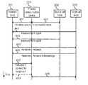
- a handover procedure in 3GPP wireless communication system typically involves a signalling sequence between a wireless communication device (denoted UE), a source eNodeB, a target eNodeB, a mobility management entity (MME) and a serving gateway (SGW).
- a conventional handover procedure as shown in FIG. 1 comprises, from the point of view of a source cell (i.e a source eNodeB) obtaining of RF signal measurements from the wireless communication device and, after having analysed the measurements, informing a target eNodeB to take over control of the wireless communication device.
- a source cell i.e a source eNodeB
- the target eNodeB controls a transfer of radio bearers between the wireless communication device and the SGW.
- a drawback with such a low radio frequency scenario is that, since a group of wireless communication devices will require a relatively high total capacity in terms of, e.g., bitrate and response time, use of larger cells having lower radio frequencies will limit the high capacity requirement. It is therefore desirable to find a way to provide high capacity to groups of wireless communication devices that is not restricted to low radio frequency solutions. In other words, a solution that makes use of higher radio frequencies and therefore enables higher capacity is desirable.
- an object of the present disclosure is to overcome or at least mitigate at least some of the drawbacks related to handover in a HST scenario.
- a method performed by a network nodefor controlling handover of a wireless communication device from a source cell to a target cell.
- the network node is maintaining a first radio cell at a first cell carrier frequency and the cell has a radio coverage that covers at least part of both the source cell and the target cell.
- the source cell is maintained by a source cell node at a source cell carrier frequency and the target cell is maintained by a target cell node at a target cell carrier frequency.
- the source cell carrier frequency and the target cell carrier frequency are higher than the first cell carrier frequency.
- the method comprises a number of actions as follows. A first performance value is estimated that is associated with communication between the wireless communication device and the source cell.
- a second performance value is estimated that is associated with communication between the wireless communication device and the target cell.
- a determination is made that the wireless communication device is about to move into coverage of the target cell. If the second performance value is greater than the current performance value, then the wireless communication device is assisted to perform a handover from the source cell to the target cell by a transmission of a handover request to the target cell, reception of a handover request acknowledgement from the target cell, and a transmission of instructions to the wireless communication device for connecting to the target cell.
- An effect of such a method is that it enables an optimization of the performance of a mobile communications network where groups of wireless communication devices are moving together at high speed, e.g. on-board high speed trains.
- the method enables the performance optimization in that it provides a multiple layered access context in terms of a low frequency layer serving as a large coverage cell (the first cell in the above summary) overlapping with multiple smaller cells with higher performance (source and target cell in the above summary) in a high frequency layer. Handover events are handled by the coverage cell, directing the wireless communication device moving at high speed to the best performance cell in the high frequency layer.
- This procedure may be done at a time based on (as will be exemplified below) speed/time estimates, positioning system or received uplink RF signal characteristics (e.g. RF fingerprint profiles etc.) without the need of performing standard handover procedures in the high frequency layer.
- wireless communication devices moving at high speed may be directed to the best performance cell at the high frequency layer at a given time and location by the low frequency layer to avoid frequent standard hand-over events and thereby ensuring high performance for the connections that are used by the wireless communication devices in the wireless communications network.
- any of the estimation of a first performance value and the estimation of a second performance value may comprise measuring RF signals received from the wireless communication device.
- any of the estimation of a first performance value and the estimation of a second performance value may comprise receiving at least one measurement report from any of the source cell and the target cell.
- the at least one measurement report comprises information associated with RF signals from the wireless communication device received and measured by any of the source cell and the target cell.
- Some embodiments comprise a determination of a spatial motion value for the wireless communication device.
- the determination that the wireless communication device is about to move into coverage of the target cell is based on the spatial motion value.
- the determination of the spatial motion value for the wireless communication device may be based, at least partly, on any of the estimated first performance value and the estimated second performance value.
- the determination of the spatial motion value for the wireless communication device may also be based, at least partly, on a-priori knowledge about spatial locations of any of the source cell and the target cell.
- the network node maintains the first radio cell such that the radio coverage of the first cell covers both the source cell and the target cell. In such embodiments, a connection is maintained between the first cell and the wireless communication device subsequent to the transmission of instructions to the wireless communication device for connecting to the target cell. In other embodiments, the network node maintains the first radio cell such that the radio coverage of the first cell covers only a part of the source cell and only a part of the target cell in an area of overlap of the first cell, the source cell and the target cell. In these embodiments, the method comprises disconnecting, subsequent to the transmission of instructions to the wireless communication device for connecting to the target cell, the wireless communication device from the first cell.
- Embodiments include those wherein any of the firs performance value and the second performance value is associated with any of a signal strength, a signal to interference ratio, SIR, and an error rate associated with a signal.
- a network node for controlling handover of a wireless communication device from a source cell to a target cell.
- the network node comprises input/output circuitry, a processor and a memory.
- the memory contains instructions executable by the processor whereby the network node is operative to maintain a first radio cell at a first cell carrier frequency having a radio coverage that covers at least part of both the source cell and the target cell.
- the source cell is maintained by a source cell node at a source cell carrier frequency and the target cell is maintained by a target cell node at a target cell carrier frequency.
- the source cell carrier frequency and the target cell carrier frequency are higher than the first cell carrier frequency.
- the network node is further operative to:
- the network node as summarized above may be embodied in various embodiments that correspond to the above summarized embodiments of a method.
- a computer program comprising instructions which, when executed on at least one processor in a network node, cause the network node to carry out the method as summarized above in connection with the first aspect and the various embodiments of this aspect.
- a carrier comprising a computer program according to the summarized aspect above, wherein the carrier is one of an electronic signal, an optical signal, a radio signal and a computer readable storage medium.
- FIG. 1 is a signaling diagram of a prior art handover procedure
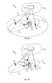
- FIGS. 2 a and 2 b schematically illustrate embodiments of a wireless communications network
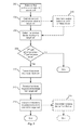
- FIG. 3 is a flowchart illustrating embodiments of methods
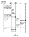
- FIGS. 4 a and 4 b are signaling diagrams illustrating embodiments of methods
- FIG. 5 schematically illustrates a network node
- FIG. 6 schematically illustrates a network node.
- the procedure of handover is the standard way in a wireless communications network to keep wireless communication devices on the move while they are being served more or less seamlessly by the wireless communications network.
- handover is a rather complicated procedure and it becomes much more troublesome to perform the necessary signalling actions in high speed scenarios where a plurality of users of wireless communication devices are sitting close to one another moving at high speed.
- a typical example is of course a high speed train as discussed above.
- Lcell coverage layer of cells
- Hcell high performance cells
- HetNet heterogeneous network
- HetNet typically comprises one or more isolated small cells under the coverage of a large cell that enables mobility and coordination between a small cell and a large cell by use of specific procedures including inter-cell interference control (ICIC) and coordinated multipoint transmission (CoMP).
- ICIC inter-cell interference control
- CoMP coordinated multipoint transmission
- the present disclosure provides embodiments that are operative such that, in addition to basic data and signalling services, an Lcell provides information between a wireless communication device and a target Hcell exchanged during a handover procedure such that handover latency from a source Hcell to the target Hcell is significantly reduced. Since the Lcell is relatively large and operates at a relatively low radio frequency, any handover events between different Lcells occur much less frequently and are easier to handle.
- such a simplified handover procedure between a source Hcell and a target Hcell is access-network-based in that the Lcell, via its own measurements or with the help of measurements obtained from the source and target Hcells, achieves higher handover accuracy.
- measurements by the wireless communication device itself are not necessarily required for deciding that a handover from the source Hcell to the target Hcell is to be performed, yet any reported wireless communication device measurements related to other procedures can be used to justify that the access-network-based handover procedure has really provided proper downlink performance to the wireless communication device.
- FIGS. 2 a and 2 b both illustrate one and the same wireless communications network 200 .
- the method is performed by a network node 201 for controlling handover of a wireless communication device from a source Hcell to a target Hcell.
- the source and target HCells will simply be denoted source cell 212 and target cell 213 , respectively.
- the network node 201 is maintaining a first cell 211 at a first cell carrier frequency and the first cell 211 has a radio coverage that covers at least part of both the source cell 212 and the target cell 213 .
- the source cell 212 is maintained by a source cell node 202 at a source cell carrier frequency and the target cell 213 is maintained by a target cell node 203 at a target cell carrier frequency. As discussed above, the source cell carrier frequency and the target cell carrier frequency are higher than the first cell carrier frequency.
- the wireless communications network 200 may comprise a large number of cells in addition to the cells 211 , 212 , 213 .
- the system 200 may comprise a plurality of Hcells, i.e. source and target cells, similar to the source cell 212 and the target cell 213 .
- the network node 201 that controls the first cell 211 as well as the source cell node 202 and the target cell node 203 may be connected to a central baseband unit 251 so as to facilitate the co-operations between the network node 201 and the source and target cell nodes 202 , 203 .
- FIG. 2 a illustrates that the network node 201 and the baseband unit 251 are separate nodes
- the network node 201 and the baseband unit 251 may be considered as separate or combined individual entities as well as a combination of a plurality of entities or functions.
- functionality of the network node 201 and the baseband unit 251 may be distributed, in terms of functionality as well as in terms of physical hardware, over one or more processing units that are residing in a logical entity that may be defined as a “cloud” 250 .
- a wireless communication device 221 in a group 261 of wireless communication devices 261 are moving along a path 205 at a high speed, as illustrated by a speed or velocity vector 222 , under the coverage of the first cell 211 and connected to the network node 201 .
- the wireless communication device 221 as well as the group 261 of wireless communication devices are also under the coverage of the source cell 212 and connected to the source cell node 202 .
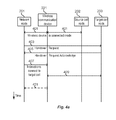
- the fact that the wireless communication device 221 is connected to both the first cell 211 and the source cell 212 is schematically illustrated in FIG. 4 a by way of signals 401 .
- the network node 201 monitors the position of the wireless communication device 221 in the group 261 relative to the source and target cells 212 , 213 (and relative to other, not illustrated, potential target cells in the wireless communications network 200 ). As a consequence of this monitoring determines whether the wireless communication device 221 is about to move from the source cell 212 into the particular target cell 213 .
- the network node 201 finds that the target cell 213 is a “better” Hcell (in terms of so-called performance values, as will be discussed in detail below) than the source cell 212 in which the wireless communication device 221 is connected, the network node 201 will request the wireless communication device 221 (as well as other wireless communication devices in the group 261 ) to configure the target cell 213 as the new Hcell and de-configure the old Hcell, i.e the source cell 212 , by means of initiating a handover procedure as will be detailed below.
- This may be performed by way of a dedicated or common RRC reconfiguration procedure so that the data streams from the wireless communication device 221 (and any other wireless communication device in the group 261 ) will reach the central baseband unit 251 via the new Hcell, i.e. the target cell 213 , and downlink data from the central baseband unit 251 will send to the wireless communication device 221 also via the new Hcell.
- Embodiments of a method will now be described with reference to a number of actions that are performed by the network node 201 , remembering that reference will be made to the wireless communications network 200 in FIG. 2 a and FIG. 2 b , the flowchart in FIG. 3 and the signaling diagrams in FIGS. 4 a and 4 b.
- An estimation is made of a first performance value associated with communication between the wireless communication device 221 and the source cell 212 .
- An estimation is made of a second performance value associated with communication between the wireless communication device 221 and the target cell 213 .
- any of the estimation of a first performance value and the estimation of a second performance value may comprise measuring RF signals received from the wireless communication device 221 .
- RF signals may be any appropriate RF signal received by the network node 201 from the wireless communication device 221 , including reference signals and any other signal that can be measured.
- embodiments include also those in which any of the estimation of a first performance value and the estimation of a second performance value may comprise (in addition to or instead of measurements performed by the network node 201 ) receiving at least one measurement report 441 , 443 from any of the source cell 212 and the target cell 213 .
- Such at least one measurement report may comprise information associated with RF signals from the wireless communication device 221 received and measured by any of the source cell 212 and the target cell 213 .
- first and second performance values may be associated with any of a signal strength, a signal to interference ratio, SIR, and an error rate associated with a signal.
- SIR signal to interference ratio
- error rate an error rate associated with a signal.
- the use of performance values is to represent a measure of how “good” a connection is between the wireless communication device 221 and a cell.
- this determination that the wireless communication device is about to move into coverage of the target cell 213 may be based on a spatial motion value(e.g. speed and/or position) that is determined in an action 305 .
- a determination of the spatial motion value for the wireless communication device 221 maybe based, at least partly, on any of the estimated first performance value and the estimated second performance value.
- a determination of the spatial motion value for the wireless communication device 221 maybe based, at least partly, on a-priori knowledge about spatial locations of any of the source cell 212 and the target cell 213 .
- criterions for the network node 201 to determine movement into the target cell 213 may be explicitly position-based, or based on estimated speed of the wireless communication device 221 and the time that it left a reference point, e.g. closest point to the Lcell (i.e. network node 201 ).
- the network node 201 may derive the wireless communication device 221 positions by match uplink RF fingerprints that it receives.
- the Hcells i.e.
- source and target cell nodes 202 , 203 may also assist the network node 201 to select a target cell by matching uplink RF fingerprints received by the source cell node 202 to indicate that the wireless communication device 221 is closer to the target cell node 203 .
- RF fingerprint is to be understood as received RF signals from multiple wireless communication devices with delay or directional profiles over time.
- Such a fingerprint matching may be realized by configuring a receiver branch in the target cell node 203 to receive the uplink RF signals from the wireless communication device 221 , followed by a comparison of measurement results of the wireless communication device 221 from the source cell node 202 and the target cell node 203 in the central baseband unit 251 (remembering that the network node 201 and the baseband unit 251 may be separate or combined nodes).
- Such a procedure can even yield receiver diversity gains of the uplink data streams if the central baseband unit 251 can combine the data received by source and the target cell nodes 202 , 203 even if the target cell 213 is not yet RRC-connected to the wireless communication device 221 explicitly.
- this action represents the above discussed check whether a target cell (here the target cell 213 ) is better than the source cell 212 to which the wireless communication device 221 is currently connected.
- a transmission is made of a handover request 403 to the target cell 213 .
- a handover request acknowledgement 405 is received from the target cell 213 .
- a transmission is made of instructions 407 to the wireless communication device 221 for connecting to the target cell 213 .
- embodiments of a method in the network node 201 may be such that the network node 201 maintains the first radio cell 211 such that the radio coverage of the first cell 211 covers both the source cell 212 and the target cell 213 and wherein a connection is maintained between the first cell 211 and the wireless communication device 221 subsequent to the transmission of instructions to the wireless communication device for connecting to the target cell.
- FIG. 2 b Such embodiments comprises disconnecting, in an action 315 , the wireless communication device 221 from the first cell 212 subsequent to the transmission (in action 314 ) of instructions to the wireless communication device 221 for connecting to the target cell 213 .Such a disconnection may involve signalling 431 between the network node 201 and the wireless communication device 221 as illustrated in FIG. 4 a or it may involve signalling 433 as illustrated in FIG. 4 b.
- inventions may be viewed as an alternative to the embodiments (illustrated in FIG. 2 a ) where a large Lcell (i.e. the first cell 211 ) covers multiple Hcells (i.e. source and target cells including the source cell 212 and the target cell 213 ).
- a large Lcell i.e. the first cell 211
- Hcells i.e. source and target cells including the source cell 212 and the target cell 213 .
- the first cell 211 has good coverage only of the overlapping area 214 where the source cell 212 and target cell 213 meet or overlap.
- the first cell 211 operates at a relatively low radio frequency and noting that it operates with reserved resources including random access resources such as random access channel (RACH) preambles, it can efficiently assist the handover process of the wireless communication device 221 between Hcells (i.e., here, from the source cell 212 to the target cell 213 ).
- the wireless communication device 221 (and also any other wireless communication device in the group 261 ) may set up a connection to the first cell 211 prior to the handover event and communicate with the first cell 211 for signalling and real time application data transfer with low bandwidth demand until it is handed-over to the target cell 213 . Then the connection with the first cell 211 may be dropped, unless a further handover between the first cell and other Lcells are needed.
- RACH random access channel
- the wireless communication device 221 may connect to the target cell 213 as illustrated by a communication procedure 409 .
- a procedure 409 may involve a random access procedure in a scenario where the source and target cells 212 , 213 are configured as normal cells with both data and control channels.
- the wireless communication device 221 may communicate as illustrated by procedure 409 and acquire data directly from the source and target cells 212 , 213 as controlled via control channels in the first cell 211 .
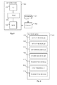
- the network node 500 is for controlling handover of a wireless communication device from a source cell to a target cell.
- the network node 500 comprises input/output circuitry 506 , a processor 502 and a memory 504 .
- the memory 504 contains instructions executable by the processor 502 whereby the network node 500 is operative to maintain a first radio cell at a first cell carrier frequency having a radio coverage that covers at least part of both the source cell and the target cell.
- the source cell is maintained by a source cell node at a source cell carrier frequency and the target cell is maintained by a target cell node at a target cell carrier frequency.
- the source cell carrier frequency and the target cell carrier frequency are higher than the first cell carrier frequency.
- the network node 600 is further operative to:
- the instructions that are executable by the processor 502 may be software in the form of a computer program 541 .
- the computer program 541 may be contained in or by a carrier 542 , which may provide the computer program 541 to the memory 504 and processor 502 .
- the carrier 542 may be in any suitable form including an electronic signal, an optical signal, a radio signal or a computer readable storage medium.
- the network node 500 is operative such that any of the estimation of a first performance value and the estimation of a second performance value comprises measuring radio frequency, RF, signals received from the wireless communication device.
- the network node 500 is operative such that any of the estimation of a first performance value and the estimation of a second performance value comprises receiving at least one measurement report from any of the source cell and the target cell, said at least one measurement report comprising information associated with RF signals from the wireless communication device received and measured by any of the source cell and the target cell.
- the network node 500 is operative to determine a spatial motion value for the wireless communication device, and operative such that the determination that the wireless communication device is about to move into coverage of the target cell is based on the spatial motion value.
- the network node 500 is operative such that the determination of the spatial motion value for the wireless communication device is based, at least partly, on any of the estimated first performance value and the estimated second performance value.
- the network node 500 is operative such that the determination of the spatial motion value for the wireless communication device is based, at least partly, on a-priori knowledge about spatial locations of any of the source cell and the target cell.
- the network node 500 is operative to maintain the first radio cell such that the radio coverage of the first cell covers both the source cell and the target cell and operative such that a connection is maintained between the first cell and the wireless communication device subsequent to the transmission of instructions to the wireless communication device for connecting to the target cell.
- the network node 500 is operative to maintain the first radio cell such that the radio coverage of the first cell covers only a part of the source cell and only a part of the target cell in an area of overlap of the first cell, the source cell and the target cell, and operative to disconnect, subsequent to the transmission of instructions to the wireless communication device for connecting to the target cell, the wireless communication device from the first cell.
- the network node 500 is operative such that any of the first performance value and the second performance value is associated with any of a signal strength, a signal to interference ratio, SIR, and an error rate associated with a signal.
- FIG. 6 illustrates schematically a network node 600 that comprises:
- the network node 600 may comprise further modules that are configured to perform in a similar manner as, e.g., the network node 500 described above in connection with FIG. 5 .
Landscapes
- Engineering & Computer Science (AREA)
- Computer Networks & Wireless Communication (AREA)
- Signal Processing (AREA)
- Mobile Radio Communication Systems (AREA)
Abstract
Description
- Embodiments herein relate to wireless communication and more specifically to control of handover in a scenario where wireless communication devices are moving at high speeds.
- Wireless communication systems, i.e. systems that provide communication services to wireless communication devices such as mobile phones, smartphones (often denoted by UE that is short for user equipment) as well as machine-type communication (MTC) devices, have evolved during the last decade into systems that must utilize the radio spectrum and other system resources in the most efficient manner possible. A reason for this is the ever increasing demand for high speed data communication capabilities in terms of, e.g., bitrate and to provide these capabilities at any given time, at any geographical location and also in scenarios where the wireless communication device is moving at a high speed, e.g., on board a high speed train (HST). To meet this demand much work is being done within the third generation partnership project (3GPP) for enhancing performance in high speed train environments. The justification is that there are railways such as Japan Tohoku Shinkansen (running at 320 km/h), German ICE (330 km/h), AGV Italo (400 km/h), and Shanghai Maglev (430 km/h) at which vehicles travel at greater speed than 300 km/h and where there is demand for a large number of simultaneous users using mobile services while being on-board such a HST.
- Given the fact that mobility is one of the corner stones of the 3GPP system, mobility management is conventionally carried out individually, e.g. base stations such as evolved NodeB's (eNodeB) in a 3GPP long term evolution (LTE) system configure radio frequency (RF) signal measurement events and provide configuration information to wireless communication devices via radio resource control (RRC) signalling. Having received such configuration information, a wireless communication device measures requested parameters such as reference signal received power (RSRP) and/or reference signal received quality (RSRQ) and reports the results back to base stations, e.g. eNodeB, periodically or when specific event criterions are met. A handover decision is made when a target cell is more suitable than a serving cell.
- As
FIG. 1 illustrates, a handover procedure in 3GPP wireless communication system typically involves a signalling sequence between a wireless communication device (denoted UE), a source eNodeB, a target eNodeB, a mobility management entity (MME) and a serving gateway (SGW). In summary, a conventional handover procedure as shown inFIG. 1 comprises, from the point of view of a source cell (i.e a source eNodeB) obtaining of RF signal measurements from the wireless communication device and, after having analysed the measurements, informing a target eNodeB to take over control of the wireless communication device. Having taken over communication with the wireless communication device via a random access (RA) procedure, the target eNodeB controls a transfer of radio bearers between the wireless communication device and the SGW. - In situations where many wireless communication devices are moving together, e.g. on-board a high speed train carrying a large number of passengers, such conventional mobile management method may become problematic due to generation of a large number of handover requests during very short time periods. Examples of such situations are described in United States patent application publication 2015/0181481 and in “An Enhanced Handover Scheme for Mobile Relays in LTE-A High-Speed Rail Networks”, IEEE Transactions on Vehicular Technology V.64 No. 2, 763 (2015).
- Existing solutions, such as those cited above, are focused on mobility management with the aim of reducing the number of handover events of the group of wireless communication devices. This means a preference for larger cells and lower radio frequencies.
- A drawback with such a low radio frequency scenario is that, since a group of wireless communication devices will require a relatively high total capacity in terms of, e.g., bitrate and response time, use of larger cells having lower radio frequencies will limit the high capacity requirement. It is therefore desirable to find a way to provide high capacity to groups of wireless communication devices that is not restricted to low radio frequency solutions. In other words, a solution that makes use of higher radio frequencies and therefore enables higher capacity is desirable.
- However, since normally cell sizes become smaller at higher radio frequencies, handover events become ever more frequent and the degradation of performance due to handovers becomes severe. Such a drawback may be mitigated by increasing the size of a cell by configuring a few radio base station radio beam sectors to form a “supercell”, yet the handover issues still need to be handled between such “supercells”.
- In view of the above, an object of the present disclosure is to overcome or at least mitigate at least some of the drawbacks related to handover in a HST scenario.
- This is achieved in a first aspect by a method performed by a network nodefor controlling handover of a wireless communication device from a source cell to a target cell. The network node is maintaining a first radio cell at a first cell carrier frequency and the cell has a radio coverage that covers at least part of both the source cell and the target cell. The source cell is maintained by a source cell node at a source cell carrier frequency and the target cell is maintained by a target cell node at a target cell carrier frequency. The source cell carrier frequency and the target cell carrier frequency are higher than the first cell carrier frequency. The method comprises a number of actions as follows. A first performance value is estimated that is associated with communication between the wireless communication device and the source cell. A second performance value is estimated that is associated with communication between the wireless communication device and the target cell. A determination is made that the wireless communication device is about to move into coverage of the target cell. If the second performance value is greater than the current performance value, then the wireless communication device is assisted to perform a handover from the source cell to the target cell by a transmission of a handover request to the target cell, reception of a handover request acknowledgement from the target cell, and a transmission of instructions to the wireless communication device for connecting to the target cell.
- An effect of such a method is that it enables an optimization of the performance of a mobile communications network where groups of wireless communication devices are moving together at high speed, e.g. on-board high speed trains. The method enables the performance optimization in that it provides a multiple layered access context in terms of a low frequency layer serving as a large coverage cell (the first cell in the above summary) overlapping with multiple smaller cells with higher performance (source and target cell in the above summary) in a high frequency layer. Handover events are handled by the coverage cell, directing the wireless communication device moving at high speed to the best performance cell in the high frequency layer.
- This procedure may be done at a time based on (as will be exemplified below) speed/time estimates, positioning system or received uplink RF signal characteristics (e.g. RF fingerprint profiles etc.) without the need of performing standard handover procedures in the high frequency layer. In short, wireless communication devices moving at high speed may be directed to the best performance cell at the high frequency layer at a given time and location by the low frequency layer to avoid frequent standard hand-over events and thereby ensuring high performance for the connections that are used by the wireless communication devices in the wireless communications network.
- In some embodiments, any of the estimation of a first performance value and the estimation of a second performance value may comprise measuring RF signals received from the wireless communication device.
- In some embodiments, any of the estimation of a first performance value and the estimation of a second performance value may comprise receiving at least one measurement report from any of the source cell and the target cell. In these embodiments, the at least one measurement report comprises information associated with RF signals from the wireless communication device received and measured by any of the source cell and the target cell.
- Some embodiments comprise a determination of a spatial motion value for the wireless communication device. In these embodiments, the determination that the wireless communication device is about to move into coverage of the target cell is based on the spatial motion value. For example, the determination of the spatial motion value for the wireless communication device may be based, at least partly, on any of the estimated first performance value and the estimated second performance value. The determination of the spatial motion value for the wireless communication device may also be based, at least partly, on a-priori knowledge about spatial locations of any of the source cell and the target cell.
- In some embodiments, the network node maintains the first radio cell such that the radio coverage of the first cell covers both the source cell and the target cell. In such embodiments, a connection is maintained between the first cell and the wireless communication device subsequent to the transmission of instructions to the wireless communication device for connecting to the target cell. In other embodiments, the network node maintains the first radio cell such that the radio coverage of the first cell covers only a part of the source cell and only a part of the target cell in an area of overlap of the first cell, the source cell and the target cell. In these embodiments, the method comprises disconnecting, subsequent to the transmission of instructions to the wireless communication device for connecting to the target cell, the wireless communication device from the first cell.
- Embodiments include those wherein any of the firs performance value and the second performance value is associated with any of a signal strength, a signal to interference ratio, SIR, and an error rate associated with a signal.
- In another aspect there is provided a network node for controlling handover of a wireless communication device from a source cell to a target cell. The network node comprises input/output circuitry, a processor and a memory. The memory contains instructions executable by the processor whereby the network node is operative to maintain a first radio cell at a first cell carrier frequency having a radio coverage that covers at least part of both the source cell and the target cell. The source cell is maintained by a source cell node at a source cell carrier frequency and the target cell is maintained by a target cell node at a target cell carrier frequency. The source cell carrier frequency and the target cell carrier frequency are higher than the first cell carrier frequency. The network node is further operative to:
-
- estimate a first performance value associated with communication between the wireless communication device and the source cell,
- estimate a second performance value associated with communication between the wireless communication device and the target cell,
- determine that the wireless communication device is about to move into coverage of the target cell, and
- if the second performance value is greater than the first performance value, then assist the wireless communication device to perform a handover from the source cell to the target cell by:
- transmit a handover request to the target cell,
- receive a handover request acknowledgement from the target cell, and
- transmit instructions to the wireless communication device for connecting to the target cell.
- The network node as summarized above may be embodied in various embodiments that correspond to the above summarized embodiments of a method.
- In another aspect there is provided a computer program, comprising instructions which, when executed on at least one processor in a network node, cause the network node to carry out the method as summarized above in connection with the first aspect and the various embodiments of this aspect.
- In another aspect there is provided a carrier comprising a computer program according to the summarized aspect above, wherein the carrier is one of an electronic signal, an optical signal, a radio signal and a computer readable storage medium.
- These other aspects provide the same effects and advantages as summarized above in connection with the method of the first aspect.
-
FIG. 1 is a signaling diagram of a prior art handover procedure, -
FIGS. 2a and 2b schematically illustrate embodiments of a wireless communications network, -
FIG. 3 is a flowchart illustrating embodiments of methods, -
FIGS. 4a and 4b are signaling diagrams illustrating embodiments of methods, -
FIG. 5 schematically illustrates a network node, and -
FIG. 6 schematically illustrates a network node. - As discussed above, the procedure of handover is the standard way in a wireless communications network to keep wireless communication devices on the move while they are being served more or less seamlessly by the wireless communications network. As
FIG. 1 illustrates, handover is a rather complicated procedure and it becomes much more troublesome to perform the necessary signalling actions in high speed scenarios where a plurality of users of wireless communication devices are sitting close to one another moving at high speed. A typical example is of course a high speed train as discussed above. In such a scenario it is easy to realize that a huge amount of handover events have to be handled by the wireless communications network within very short periods of time. Failing such handover handling will inevitably result in a deteriorated performance of the wireless communications network, e.g. in terms of interrupted and lost connections. - In order to simplify the standard handover procedure and thereby mitigate drawbacks of prior art solutions, it is proposed herein to provide, in a wireless communications network, a coverage layer of cells (Lcell) where an Lcell operates at a first relatively low radio frequency. The Lcell covers a plurality of high performance cells (Hcell), which are similar to normal cells or supercells at higher radio frequencies. Such a scenario may be considered as a multiple layered access network, which in some aspects may be seem related to prior art multiple layer networks such as the so-called heterogeneous network (HetNet) defined by 3GPP. However, the present disclosure differs from, e.g., HetNet that typically comprises one or more isolated small cells under the coverage of a large cell that enables mobility and coordination between a small cell and a large cell by use of specific procedures including inter-cell interference control (ICIC) and coordinated multipoint transmission (CoMP).
- In contrast, the present disclosure provides embodiments that are operative such that, in addition to basic data and signalling services, an Lcell provides information between a wireless communication device and a target Hcell exchanged during a handover procedure such that handover latency from a source Hcell to the target Hcell is significantly reduced. Since the Lcell is relatively large and operates at a relatively low radio frequency, any handover events between different Lcells occur much less frequently and are easier to handle.
- As described in detail below, such a simplified handover procedure between a source Hcell and a target Hcell is access-network-based in that the Lcell, via its own measurements or with the help of measurements obtained from the source and target Hcells, achieves higher handover accuracy. In contrast to prior art handover procedures, measurements by the wireless communication device itself are not necessarily required for deciding that a handover from the source Hcell to the target Hcell is to be performed, yet any reported wireless communication device measurements related to other procedures can be used to justify that the access-network-based handover procedure has really provided proper downlink performance to the wireless communication device.
- Now with reference to
FIGS. 2a -b,FIG. 3 andFIGS. 4a -b, exemplary embodiments of a method will be described in some detail.FIGS. 2a and 2b both illustrate one and the samewireless communications network 200. The method is performed by anetwork node 201 for controlling handover of a wireless communication device from a source Hcell to a target Hcell. It is to be noted that the source and target HCells will simply be denotedsource cell 212 andtarget cell 213, respectively. Thenetwork node 201 is maintaining afirst cell 211 at a first cell carrier frequency and thefirst cell 211 has a radio coverage that covers at least part of both thesource cell 212 and thetarget cell 213. Thesource cell 212 is maintained by asource cell node 202 at a source cell carrier frequency and thetarget cell 213 is maintained by atarget cell node 203 at a target cell carrier frequency. As discussed above, the source cell carrier frequency and the target cell carrier frequency are higher than the first cell carrier frequency. - As the skilled person will realize, the
wireless communications network 200 may comprise a large number of cells in addition to thecells system 200 may comprise a plurality of Hcells, i.e. source and target cells, similar to thesource cell 212 and thetarget cell 213. - As
FIG. 2a exemplifies, thenetwork node 201 that controls thefirst cell 211 as well as thesource cell node 202 and the target cell node 203may be connected to acentral baseband unit 251 so as to facilitate the co-operations between thenetwork node 201 and the source andtarget cell nodes - Although
FIG. 2a (andFIG. 2b ) illustrate that thenetwork node 201 and thebaseband unit 251 are separate nodes, it is also to be noted that thenetwork node 201 and thebaseband unit 251 may be considered as separate or combined individual entities as well as a combination of a plurality of entities or functions. For example, functionality of the network node 201and thebaseband unit 251 may be distributed, in terms of functionality as well as in terms of physical hardware, over one or more processing units that are residing in a logical entity that may be defined as a “cloud” 250. - Furthermore, as illustrated in 2a, a
wireless communication device 221 in agroup 261 ofwireless communication devices 261 are moving along apath 205 at a high speed, as illustrated by a speed orvelocity vector 222, under the coverage of thefirst cell 211 and connected to thenetwork node 201. Thewireless communication device 221 as well as thegroup 261 of wireless communication devices are also under the coverage of thesource cell 212 and connected to thesource cell node 202. The fact that thewireless communication device 221 is connected to both thefirst cell 211 and thesource cell 212 is schematically illustrated inFIG. 4a by way ofsignals 401. - As will be described in the following, the
network node 201 monitors the position of thewireless communication device 221 in thegroup 261 relative to the source andtarget cells 212, 213 (and relative to other, not illustrated, potential target cells in the wireless communications network 200). As a consequence of this monitoring determines whether thewireless communication device 221 is about to move from thesource cell 212 into theparticular target cell 213. Moreover, if thenetwork node 201 finds that thetarget cell 213 is a “better” Hcell (in terms of so-called performance values, as will be discussed in detail below) than thesource cell 212 in which thewireless communication device 221 is connected, thenetwork node 201 will request the wireless communication device 221 (as well as other wireless communication devices in the group 261) to configure thetarget cell 213 as the new Hcell and de-configure the old Hcell, i.e thesource cell 212, by means of initiating a handover procedure as will be detailed below. This may be performed by way of a dedicated or common RRC reconfiguration procedure so that the data streams from the wireless communication device 221 (and any other wireless communication device in the group 261) will reach thecentral baseband unit 251 via the new Hcell, i.e. thetarget cell 213, and downlink data from thecentral baseband unit 251 will send to thewireless communication device 221 also via the new Hcell. - Embodiments of a method will now be described with reference to a number of actions that are performed by the
network node 201, remembering that reference will be made to thewireless communications network 200 inFIG. 2a andFIG. 2b , the flowchart inFIG. 3 and the signaling diagrams inFIGS. 4a and 4 b. -
Action 302 - An estimation is made of a first performance value associated with communication between the
wireless communication device 221 and thesource cell 212. -
Action 304 - An estimation is made of a second performance value associated with communication between the
wireless communication device 221 and thetarget cell 213. - Any of the estimation of a first performance value and the estimation of a second performance value may comprise measuring RF signals received from the
wireless communication device 221. Although not illustrated explicitly in the signalling diagram ofFIG. 4a , it is to be noted that such RF signals may be any appropriate RF signal received by thenetwork node 201 from thewireless communication device 221, including reference signals and any other signal that can be measured. - As illustrated in
FIG. 4b , embodiments include also those in which any of the estimation of a first performance value and the estimation of a second performance value may comprise (in addition to or instead of measurements performed by the network node 201) receiving at least onemeasurement report source cell 212 and thetarget cell 213. Such at least one measurement report may comprise information associated with RF signals from thewireless communication device 221 received and measured by any of thesource cell 212 and thetarget cell 213. - For example, regarding the first and second performance values, these may be associated with any of a signal strength, a signal to interference ratio, SIR, and an error rate associated with a signal. As briefly discussed above, the use of performance values is to represent a measure of how “good” a connection is between the
wireless communication device 221 and a cell. -
Action 306 - A determination is made that the
wireless communication device 221 is about to move into coverage of thetarget cell 213. - For example, this determination that the wireless communication device is about to move into coverage of the
target cell 213 may be based on a spatial motion value(e.g. speed and/or position) that is determined in anaction 305. Such a determination of the spatial motion value for thewireless communication device 221 maybe based, at least partly, on any of the estimated first performance value and the estimated second performance value. Also, such a determination of the spatial motion value for thewireless communication device 221 maybe based, at least partly, on a-priori knowledge about spatial locations of any of thesource cell 212 and thetarget cell 213. - In other words, criterions for the
network node 201 to determine movement into thetarget cell 213 may be explicitly position-based, or based on estimated speed of thewireless communication device 221 and the time that it left a reference point, e.g. closest point to the Lcell (i.e. network node 201). In a more advanced manner, thenetwork node 201 may derive thewireless communication device 221 positions by match uplink RF fingerprints that it receives. Moreover, the Hcells (i.e. source andtarget cell nodes 202, 203) may also assist thenetwork node 201 to select a target cell by matching uplink RF fingerprints received by thesource cell node 202 to indicate that thewireless communication device 221 is closer to thetarget cell node 203. (RF fingerprint is to be understood as received RF signals from multiple wireless communication devices with delay or directional profiles over time.) - Such a fingerprint matching may be realized by configuring a receiver branch in the
target cell node 203 to receive the uplink RF signals from thewireless communication device 221, followed by a comparison of measurement results of thewireless communication device 221 from thesource cell node 202 and thetarget cell node 203 in the central baseband unit 251 (remembering that thenetwork node 201 and thebaseband unit 251 may be separate or combined nodes). Such a procedure can even yield receiver diversity gains of the uplink data streams if thecentral baseband unit 251 can combine the data received by source and thetarget cell nodes target cell 213 is not yet RRC-connected to thewireless communication device 221 explicitly. -
Action 308 - A check is made whether or not the second performance value is greater than the first performance value. If that is the case, then the wireless communication device is assisted to perform a handover from the source cell to the target cell by actions 310-314.
- In other words, this action represents the above discussed check whether a target cell (here the target cell 213) is better than the
source cell 212 to which thewireless communication device 221 is currently connected. -
Action 310 - A transmission is made of a
handover request 403 to thetarget cell 213. -
Action 312 - A
handover request acknowledgement 405 is received from thetarget cell 213. -
Action 314 - A transmission is made of
instructions 407 to thewireless communication device 221 for connecting to thetarget cell 213. - As
FIG. 2a illustrates, embodiments of a method in thenetwork node 201 may be such that thenetwork node 201 maintains thefirst radio cell 211 such that the radio coverage of thefirst cell 211 covers both thesource cell 212 and thetarget cell 213 and wherein a connection is maintained between thefirst cell 211 and thewireless communication device 221 subsequent to the transmission of instructions to the wireless communication device for connecting to the target cell. - Other embodiments of the method in the
network node 201 may entail thenetwork node 201 maintaining thefirst radio cell 211 such that the radio coverage of thefirst cell 211 covers only a part of thesource cell 212 and only a part of thetarget cell 213 in an area ofoverlap 214 of thefirst cell 211, thesource cell 212 and thetarget cell 213. This is illustrated inFIG. 2b . Such embodiments comprises disconnecting, in anaction 315, thewireless communication device 221 from thefirst cell 212 subsequent to the transmission (in action 314) of instructions to thewireless communication device 221 for connecting to the target cell 213.Such a disconnection may involve signalling 431 between thenetwork node 201 and thewireless communication device 221 as illustrated inFIG. 4a or it may involve signalling 433 as illustrated inFIG. 4 b. - These embodiments may be viewed as an alternative to the embodiments (illustrated in
FIG. 2a ) where a large Lcell (i.e. the first cell 211) covers multiple Hcells (i.e. source and target cells including thesource cell 212 and the target cell 213). A characteristic of these embodiments is that thefirst cell 211 has good coverage only of the overlappingarea 214 where thesource cell 212 andtarget cell 213 meet or overlap. Remembering that thefirst cell 211 operates at a relatively low radio frequency and noting that it operates with reserved resources including random access resources such as random access channel (RACH) preambles, it can efficiently assist the handover process of thewireless communication device 221 between Hcells (i.e., here, from thesource cell 212 to the target cell 213). The wireless communication device 221 (and also any other wireless communication device in the group 261) may set up a connection to thefirst cell 211 prior to the handover event and communicate with thefirst cell 211 for signalling and real time application data transfer with low bandwidth demand until it is handed-over to thetarget cell 213. Then the connection with thefirst cell 211 may be dropped, unless a further handover between the first cell and other Lcells are needed. Such a solution is cost effective and especially valuable for assisting handover between supercells operating at high frequencies where random access can be rather challenging. - Having received the
instructions 407, thewireless communication device 221 may connect to thetarget cell 213 as illustrated by acommunication procedure 409. Such aprocedure 409 may involve a random access procedure in a scenario where the source andtarget cells target cells wireless communication device 221 may communicate as illustrated byprocedure 409 and acquire data directly from the source andtarget cells 212, 213as controlled via control channels in thefirst cell 211. - Turning now to
FIG. 5 , a schematically illustratednetwork node 500 will be described in some more detail. Thenetwork node 500 is for controlling handover of a wireless communication device from a source cell to a target cell. Thenetwork node 500 comprises input/output circuitry506, aprocessor 502 and amemory 504. Thememory 504 contains instructions executable by theprocessor 502 whereby thenetwork node 500 is operative to maintain a first radio cell at a first cell carrier frequency having a radio coverage that covers at least part of both the source cell and the target cell. The source cell is maintained by a source cell node at a source cell carrier frequency and the target cell is maintained by a target cell node at a target cell carrier frequency. The source cell carrier frequency and the target cell carrier frequency are higher than the first cell carrier frequency. Thenetwork node 600 is further operative to: -
- estimate a first performance value associated with communication between the wireless communication device and the source cell,
- estimate a second performance value associated with communication between the wireless communication device and the target cell,
- determine that the wireless communication device is about to move into coverage of the target cell, and
- if the second performance value is greater than the first performance value, then assist the wireless communication device to perform a handover from the source cell to the target cell by:
- transmit a handover request to the target cell,
- receive a handover request acknowledgement from the target cell, and
- transmit instructions to the wireless communication device for connecting to the target cell.
- The instructions that are executable by the
processor 502 may be software in the form of acomputer program 541. Thecomputer program 541 may be contained in or by acarrier 542, which may provide thecomputer program 541 to thememory 504 andprocessor 502. Thecarrier 542 may be in any suitable form including an electronic signal, an optical signal, a radio signal or a computer readable storage medium. - In some embodiments, the
network node 500 is operative such that any of the estimation of a first performance value and the estimation of a second performance value comprises measuring radio frequency, RF, signals received from the wireless communication device. - In some embodiments, the
network node 500 is operative such that any of the estimation of a first performance value and the estimation of a second performance value comprises receiving at least one measurement report from any of the source cell and the target cell, said at least one measurement report comprising information associated with RF signals from the wireless communication device received and measured by any of the source cell and the target cell. - In some embodiments, the
network node 500 is operative to determine a spatial motion value for the wireless communication device, and operative such that the determination that the wireless communication device is about to move into coverage of the target cell is based on the spatial motion value. - In some embodiments, the
network node 500 is operative such that the determination of the spatial motion value for the wireless communication device is based, at least partly, on any of the estimated first performance value and the estimated second performance value. - In some embodiments, the
network node 500 is operative such that the determination of the spatial motion value for the wireless communication device is based, at least partly, on a-priori knowledge about spatial locations of any of the source cell and the target cell. - In some embodiments, the
network node 500 is operative to maintain the first radio cell such that the radio coverage of the first cell covers both the source cell and the target cell and operative such that a connection is maintained between the first cell and the wireless communication device subsequent to the transmission of instructions to the wireless communication device for connecting to the target cell. - In some embodiments, the
network node 500 is operative to maintain the first radio cell such that the radio coverage of the first cell covers only a part of the source cell and only a part of the target cell in an area of overlap of the first cell, the source cell and the target cell, and operative to disconnect, subsequent to the transmission of instructions to the wireless communication device for connecting to the target cell, the wireless communication device from the first cell. - In some embodiments, the
network node 500 is operative such that any of the first performance value and the second performance value is associated with any of a signal strength, a signal to interference ratio, SIR, and an error rate associated with a signal. -
FIG. 6 , illustrates schematically anetwork node 600 that comprises: -
- an estimating module602 configured to estimate a first performance value associated with communication between the wireless communication device and a source cell,
- an estimating module604 configured to estimate a second performance value associated with communication between the wireless communication device and a target cell,
- a determining module606 configured to determine that the wireless communication device is about to move into coverage of the target cell, and
- an if-checking
module 608 configured to check if the second performance value is greater than the first performance value, then assist the wireless communication device to perform a handover from the source cell to the target cell by:- a
transmitting module 610 configured to transmit a handover request to the target cell, - a
receiving module 612 configured to receive a handover request acknowledgement from the target cell, and - a
transmitting module 614 configured to transmit instructions to the wireless communication device for connecting to the target cell.
- a
- The
network node 600 may comprise further modules that are configured to perform in a similar manner as, e.g., thenetwork node 500 described above in connection withFIG. 5 .
Claims (20)
Applications Claiming Priority (1)
| Application Number | Priority Date | Filing Date | Title |
|---|---|---|---|
| PCT/EP2016/061680 WO2017202454A1 (en) | 2016-05-24 | 2016-05-24 | Improved handover in high speed scenario |
Publications (2)
| Publication Number | Publication Date |
|---|---|
| US20180098260A1 true US20180098260A1 (en) | 2018-04-05 |
| US10341926B2 US10341926B2 (en) | 2019-07-02 |
Family
ID=56081475
Family Applications (1)
| Application Number | Title | Priority Date | Filing Date |
|---|---|---|---|
| US15/322,444 Expired - Fee Related US10341926B2 (en) | 2016-05-24 | 2016-05-24 | Handover in high speed scenario |
Country Status (2)
| Country | Link |
|---|---|
| US (1) | US10341926B2 (en) |
| WO (1) | WO2017202454A1 (en) |
Cited By (4)
| Publication number | Priority date | Publication date | Assignee | Title |
|---|---|---|---|---|
| US10392036B2 (en) * | 2015-03-05 | 2019-08-27 | Mitsubishi Electric Corporation | Train control system, base station control device, and ground wireless base station system |
| US11012904B2 (en) * | 2019-05-02 | 2021-05-18 | Qualcomm Incorporated | Conditional handover (CHO) deconfiguration and failure handling in wireless communications |
| CN113660641A (en) * | 2021-08-18 | 2021-11-16 | 中车青岛四方机车车辆股份有限公司 | Magnetic levitation train ground wireless communication system |
| CN113727397A (en) * | 2021-08-25 | 2021-11-30 | 深圳国人无线通信有限公司 | Method for cooperative communication of high-low frequency network system |
Families Citing this family (1)
| Publication number | Priority date | Publication date | Assignee | Title |
|---|---|---|---|---|
| CN110290565B (en) * | 2019-06-26 | 2021-11-23 | 中信科移动通信技术股份有限公司 | Access layer context management method and device |
Family Cites Families (11)
| Publication number | Priority date | Publication date | Assignee | Title |
|---|---|---|---|---|
| GB2385745B (en) * | 2002-02-21 | 2004-06-09 | Motorola Inc | A method and apparatus for selecting carriers |
| EP2649842B1 (en) | 2010-12-07 | 2019-02-27 | Telefonaktiebolaget LM Ericsson (publ) | Handover in a radio network |
| EP2716101A1 (en) | 2011-05-23 | 2014-04-09 | InterDigital Patent Holdings, Inc. | Apparatus and methods for group wireless transmit/receive unit (wtru) handover |
| CN109275168B (en) | 2012-05-03 | 2021-06-01 | 瑞典华为技术有限公司 | System and method for optimizing switching parameter settings of terminals on public transportation platform |
| EP2880913B1 (en) | 2012-08-03 | 2019-08-07 | Telefonaktiebolaget LM Ericsson (publ) | Method and arrangement for mobility procedures |
| US8837290B2 (en) | 2012-12-04 | 2014-09-16 | Telefonaktiebolaget L M Ericsson (Publ) | Handover in a soft cell network |
| CN103874149B (en) * | 2012-12-10 | 2020-06-09 | 索尼公司 | Mobile handover management method, equipment and system in wireless communication network |
| US9131421B2 (en) * | 2013-03-15 | 2015-09-08 | Nokia Solutions And Networks Oy | Methods and apparatus for handover management |
| JP2016521530A (en) * | 2013-05-13 | 2016-07-21 | アルカテル−ルーセント | Method for determining mobility of a user equipment having dual connectivity in a communication system |
| HUE043397T2 (en) | 2014-08-20 | 2019-08-28 | Ericsson Telefon Ab L M | Method and apparatus for coordinating resources |
| EP3205148B1 (en) | 2014-10-07 | 2019-01-30 | Telefonaktiebolaget LM Ericsson (publ) | Mobility in dense networks |
-
2016
- 2016-05-24 WO PCT/EP2016/061680 patent/WO2017202454A1/en active Application Filing
- 2016-05-24 US US15/322,444 patent/US10341926B2/en not_active Expired - Fee Related
Cited By (6)
| Publication number | Priority date | Publication date | Assignee | Title |
|---|---|---|---|---|
| US10392036B2 (en) * | 2015-03-05 | 2019-08-27 | Mitsubishi Electric Corporation | Train control system, base station control device, and ground wireless base station system |
| US11012904B2 (en) * | 2019-05-02 | 2021-05-18 | Qualcomm Incorporated | Conditional handover (CHO) deconfiguration and failure handling in wireless communications |
| CN113748709A (en) * | 2019-05-02 | 2021-12-03 | 高通股份有限公司 | Conditional Handover (CHO) deconfiguration and failure handling in wireless communications |
| US11849360B2 (en) | 2019-05-02 | 2023-12-19 | Qualcomm Incorporated | Conditional handover (CHO) deconfiguration and failure handling in wireless communications |
| CN113660641A (en) * | 2021-08-18 | 2021-11-16 | 中车青岛四方机车车辆股份有限公司 | Magnetic levitation train ground wireless communication system |
| CN113727397A (en) * | 2021-08-25 | 2021-11-30 | 深圳国人无线通信有限公司 | Method for cooperative communication of high-low frequency network system |
Also Published As
| Publication number | Publication date |
|---|---|
| US10341926B2 (en) | 2019-07-02 |
| WO2017202454A1 (en) | 2017-11-30 |
Similar Documents
| Publication | Publication Date | Title |
|---|---|---|
| US11051155B2 (en) | Communication system | |
| US11653276B2 (en) | Apparatus and method in wireless communication system and computer readable storage medium | |
| US11265749B2 (en) | Device, method, and computer readable storage medium in wireless communication system | |
| US10743283B2 (en) | Radio operation switch based on PS mobility data | |
| US10306524B2 (en) | Radio cell arrangement in high speed scenario | |
| US9860807B2 (en) | Handover in high speed scenario | |
| US20190342818A1 (en) | Radio communication system, base station, mobile station, communication control method, and computer readable medium | |
| US9332474B2 (en) | Signaling support for multi sector deployment in cellular communications | |
| US10341926B2 (en) | Handover in high speed scenario | |
| US20190182732A1 (en) | Telecommunications system, terminal device, infrastructure equipment and methods | |
| KR20160012736A (en) | Apparatus and method for controlling an adaptive flow in wireless communication system | |
| EP3342064B1 (en) | Power control in high speed scenario | |
| US10419974B2 (en) | Random access handling in single frequency network with unidirectional antenna node arrangement | |
| EP4362547A1 (en) | Ue reporting uplink measurements with mpe event indication | |
| WO2024002648A1 (en) | Methods, communications devices, and non-terrestrial infrastructure equipment |
Legal Events
| Date | Code | Title | Description |
|---|---|---|---|
| AS | Assignment |
Owner name: TELEFONAKTIEBOLAGET LM ERICSSON (PUBL), SWEDEN Free format text: NUNC PRO TUNC ASSIGNMENT;ASSIGNORS:PALENIUS, TORGNY;WANG, XIAOHUI;SIGNING DATES FROM 20160613 TO 20160614;REEL/FRAME:040777/0153 |
|
| STPP | Information on status: patent application and granting procedure in general |
Free format text: NOTICE OF ALLOWANCE MAILED -- APPLICATION RECEIVED IN OFFICE OF PUBLICATIONS |
|
| STPP | Information on status: patent application and granting procedure in general |
Free format text: PUBLICATIONS -- ISSUE FEE PAYMENT VERIFIED |
|
| STCF | Information on status: patent grant |
Free format text: PATENTED CASE |
|
| FEPP | Fee payment procedure |
Free format text: MAINTENANCE FEE REMINDER MAILED (ORIGINAL EVENT CODE: REM.); ENTITY STATUS OF PATENT OWNER: LARGE ENTITY |
|
| LAPS | Lapse for failure to pay maintenance fees |
Free format text: PATENT EXPIRED FOR FAILURE TO PAY MAINTENANCE FEES (ORIGINAL EVENT CODE: EXP.); ENTITY STATUS OF PATENT OWNER: LARGE ENTITY |
|
| STCH | Information on status: patent discontinuation |
Free format text: PATENT EXPIRED DUE TO NONPAYMENT OF MAINTENANCE FEES UNDER 37 CFR 1.362 |
|
| FP | Lapsed due to failure to pay maintenance fee |
Effective date: 20230702 |