US20160051069A1 - Universal Lid for Food and Drink Containers - Google Patents
Universal Lid for Food and Drink Containers Download PDFInfo
- Publication number
- US20160051069A1 US20160051069A1 US14/779,396 US201414779396A US2016051069A1 US 20160051069 A1 US20160051069 A1 US 20160051069A1 US 201414779396 A US201414779396 A US 201414779396A US 2016051069 A1 US2016051069 A1 US 2016051069A1
- Authority
- US
- United States
- Prior art keywords
- lid
- flexible
- top wall
- sidewall
- universal lid
- Prior art date
- Legal status (The legal status is an assumption and is not a legal conclusion. Google has not performed a legal analysis and makes no representation as to the accuracy of the status listed.)
- Granted
Links
Images


Classifications
-
- A—HUMAN NECESSITIES
- A47—FURNITURE; DOMESTIC ARTICLES OR APPLIANCES; COFFEE MILLS; SPICE MILLS; SUCTION CLEANERS IN GENERAL
- A47G—HOUSEHOLD OR TABLE EQUIPMENT
- A47G19/00—Table service
- A47G19/22—Drinking vessels or saucers used for table service
- A47G19/2205—Drinking glasses or vessels
- A47G19/2266—Means for facilitating drinking, e.g. for infants or invalids
- A47G19/2272—Means for facilitating drinking, e.g. for infants or invalids from drinking glasses or cups comprising lids or covers
-
- A—HUMAN NECESSITIES
- A61—MEDICAL OR VETERINARY SCIENCE; HYGIENE
- A61J—CONTAINERS SPECIALLY ADAPTED FOR MEDICAL OR PHARMACEUTICAL PURPOSES; DEVICES OR METHODS SPECIALLY ADAPTED FOR BRINGING PHARMACEUTICAL PRODUCTS INTO PARTICULAR PHYSICAL OR ADMINISTERING FORMS; DEVICES FOR ADMINISTERING FOOD OR MEDICINES ORALLY; BABY COMFORTERS; DEVICES FOR RECEIVING SPITTLE
- A61J11/00—Teats
- A61J11/0035—Teats having particular shape or structure
- A61J11/0065—Teats having particular shape or structure for improving rigidity, e.g. anti-bite-through or anti-collapsing
-
- A—HUMAN NECESSITIES
- A61—MEDICAL OR VETERINARY SCIENCE; HYGIENE
- A61J—CONTAINERS SPECIALLY ADAPTED FOR MEDICAL OR PHARMACEUTICAL PURPOSES; DEVICES OR METHODS SPECIALLY ADAPTED FOR BRINGING PHARMACEUTICAL PRODUCTS INTO PARTICULAR PHYSICAL OR ADMINISTERING FORMS; DEVICES FOR ADMINISTERING FOOD OR MEDICINES ORALLY; BABY COMFORTERS; DEVICES FOR RECEIVING SPITTLE
- A61J11/00—Teats
- A61J11/02—Teats with means for supplying air
-
- A—HUMAN NECESSITIES
- A61—MEDICAL OR VETERINARY SCIENCE; HYGIENE
- A61J—CONTAINERS SPECIALLY ADAPTED FOR MEDICAL OR PHARMACEUTICAL PURPOSES; DEVICES OR METHODS SPECIALLY ADAPTED FOR BRINGING PHARMACEUTICAL PRODUCTS INTO PARTICULAR PHYSICAL OR ADMINISTERING FORMS; DEVICES FOR ADMINISTERING FOOD OR MEDICINES ORALLY; BABY COMFORTERS; DEVICES FOR RECEIVING SPITTLE
- A61J11/00—Teats
- A61J11/04—Teats with means for fastening to bottles
- A61J11/045—Teats with means for fastening to bottles with interlocking means, e.g. protrusions or indentations on the teat
-
- B—PERFORMING OPERATIONS; TRANSPORTING
- B65—CONVEYING; PACKING; STORING; HANDLING THIN OR FILAMENTARY MATERIAL
- B65D—CONTAINERS FOR STORAGE OR TRANSPORT OF ARTICLES OR MATERIALS, e.g. BAGS, BARRELS, BOTTLES, BOXES, CANS, CARTONS, CRATES, DRUMS, JARS, TANKS, HOPPERS, FORWARDING CONTAINERS; ACCESSORIES, CLOSURES, OR FITTINGS THEREFOR; PACKAGING ELEMENTS; PACKAGES
- B65D47/00—Closures with filling and discharging, or with discharging, devices
- B65D47/04—Closures with discharging devices other than pumps
- B65D47/06—Closures with discharging devices other than pumps with pouring spouts or tubes; with discharge nozzles or passages
-
- B—PERFORMING OPERATIONS; TRANSPORTING
- B65—CONVEYING; PACKING; STORING; HANDLING THIN OR FILAMENTARY MATERIAL
- B65D—CONTAINERS FOR STORAGE OR TRANSPORT OF ARTICLES OR MATERIALS, e.g. BAGS, BARRELS, BOTTLES, BOXES, CANS, CARTONS, CRATES, DRUMS, JARS, TANKS, HOPPERS, FORWARDING CONTAINERS; ACCESSORIES, CLOSURES, OR FITTINGS THEREFOR; PACKAGING ELEMENTS; PACKAGES
- B65D47/00—Closures with filling and discharging, or with discharging, devices
- B65D47/04—Closures with discharging devices other than pumps
- B65D47/32—Closures with discharging devices other than pumps with means for venting
Definitions
- the present disclosure is directed to a universal lid for food and drink containers. More particularly, the present disclosure is directed to a universal lid that can be applied to containers of various sizes and includes an opening for accessing the contents without removing the lid.
- lids and containers can use up limited storage space in the kitchen.
- sippy cups, snack traps and/or travel mugs can increase the need for a large bag and toting around multiple devices.
- lids While many spill-proof lids have been created which allow food and drink access by mouth or hand, they are not versatile and can only fit one particularly sized vessel. Without the required sized vessel, the lid becomes useless. Some lids have been created to fit a selective number of different sized containers. However, these lids are also useless with out the matching containers. Furthermore, these lids may not include an area which allows you to drink the liquid or reach in to pull food out. As a result, you must remove the lid to drink or eat, which could be messy.
- the present disclosure relates to a stretchy, flexible lid, which can be pulled over a container or vessel used to hold liquid or food.
- This flexible lid may contain a spill-proof access point by which liquid can be drunk from the mouth and/or food can be reached with fingers or otherwise retrieved.
- the flexibility of the lid material allows it to be stretched to fit over a variety of vessels of different shapes and sizes. This universality or ability of the lid to change sizes makes the lid practical for use anywhere that food and drink are consumed including, but not limited to, in the house, in the car, at restaurants, outdoors, while traveling or on-the-go.
- the lid of the present disclosure provides an easy to use, inexpensive to manufacture lid for various uses. The lid also allows a caregiver to select the container material for their child.
- the present invention uniquely allows a user to add a spill-proof lid to any drinking cup in one's possession such as in a kitchen cupboard, at a restaurant or anywhere.
- the present lid includes a flexible top wall with an outlet and a flexible sidewall integrally formed therewith.
- the top wall and sidewall can be stretched to fit a plurality of different sized containers and allow access to food or liquid therein without removing the lid.
- the flexible sidewall stretches from an initial state to a second state where the top wall and said sidewall are taut and the flexible sidewall closes the container opening. In use, a user can obtain a fluid from the container through the outlet.
- the outlet may be sealable and may be self-sealing.
- the outlet is selectively openable. When a user applies pressure by mouth or by inserting their hand, the outlet is in an open state. When the user releases the pressure, by removing their mouth ceasing sucking or removing their hand from the outlet, the outlet automatically closes.
- a seal may be created between the container sidewall and the flexible sidewall.
- the top wall may include a spout, a stopper and opening arrangement, opening sized to fit a variety of different sized straws, or an opening sized to fit a user's hand.
- the lid may include one or more of the following features: a hinge for folding the lid for storage, integrally formed handle(s), roll-stop projection(s), a vent hole, a securing strap, a tapered sidewall.
- the diameter of the lid at the top may be greater than the diameter of the lid at the bottom.
- FIG. 1 is a perspective view of a first exemplary universal lid of the present disclosure showing a spill-proof mouthpiece suitable for liquid applications for children, the lid is shown exploded from a container;
- FIG. 2 is a top view of the first exemplary lid of FIG. 1 ;
- FIG. 3 is a bottom view of the first exemplary lid of FIG. 1 ;
- FIG. 4 is a front view of the first exemplary lid of FIG. 1 ;
- FIG. 5 is a side view of the first exemplary lid of FIG. 1 ;
- FIG. 6 is a cross-sectional view of the first exemplary lid of FIG. 1 installed on the container of FIG. 1 ;
- FIG. 7 is a perspective view of a second exemplary lid of the present disclosure showing a spill-proof mouthpiece with a leak-proof seal feature near a closed position, more suitable for adult use;
- FIG. 8 is a perspective view of the second exemplary lid of FIG. 6 with the seal feature in an open position
- FIG. 9 is a side view of the second exemplary lid of FIG. 6 ;
- FIG. 10 is a perspective view of a third exemplary lid of the present disclosure showing the lid on a container
- FIG. 11 is a perspective view of a fourth exemplary lid of the present disclosure showing a spill-proof access point suitable for liquid applications for adult use;
- FIG. 12 is a top view of the fourth exemplary lid of FIG. 11 ;
- FIG. 13 is a front view of the fourth exemplary lid of FIG. 11 ;
- FIG. 14 is a cross-sectional view of the fourth exemplary lid along line 14 - 14 of FIG. 13 ;
- FIG. 15 is a front, perspective view of a fifth exemplary lid of the present disclosure showing a spill-proof access point suitable for liquid applications for children;
- FIG. 16 is a rear, perspective view of the fifth exemplary lid of FIG. 15 ;
- FIG. 17 is a cross-sectional view of the fifth exemplary lid of FIG. 15 along line 17 - 17 of FIG. 16 , with the lid shown in an original state;
- FIG. 18 is a cross-sectional view of two fifth exemplary lids of FIG. 15 shown in a folded state and stacked, where an alternative vent is shown;
- FIG. 19 is a cross-sectional view of the fifth exemplary lid of FIG. 15 along line 19 - 19 of FIG. 16 , with the lid shown in an original state;
- FIG. 20 is a side, perspective view of the fifth exemplary lid of FIG. 15 shown in use;
- FIGS. 21-22 are perspective views of a sixth exemplary lid of the present disclosure showing a spill-proof access point suitable for liquid applications for children, where the lid is connected to two different containers;
- FIG. 23 is a perspective view of a seventh exemplary lid of the present disclosure showing a spill-proof access point suitable for liquid applications for children, where the spout is in an open position;
- FIG. 24 is a cross-sectional view of the seventh exemplary lid of FIG. 23 along line 24 - 24 thereof;
- FIG. 25 is a perspective view of the seventh exemplary lid of FIG. 23 , where the spout is in a closed or folded position;
- FIG. 26 is a perspective view of a eighth exemplary lid of the present disclosure showing a spill-proof access point suitable for liquid applications for children, where a strap and a spout are in an open position;
- FIG. 27 is a perspective view of the eighth exemplary lid of FIG. 26 , where the strap is in a closed position;
- FIG. 28 is a perspective view of the eighth exemplary lid of FIG. 26 , where the strap and spout are in a closed position;
- FIG. 29 is a perspective view of a ninth exemplary lid of the present disclosure showing a spill-proof access point suitable for liquid applications for children;
- FIG. 30 is a partial, cross-sectional view of the ninth exemplary lid of FIG. 29 ;
- FIG. 31 is a side view of the ninth exemplary lid of FIG. 29 , with the lid shown in an original state;
- FIG. 32 is a cross-sectional view of the ninth exemplary lid of FIG. 29 shown in a folded state, where an alternative vent is shown;
- FIG. 33 cross-sectional view of the ninth exemplary lid of FIG. 29 in use
- FIGS. 34-35 are perspective views of the ninth exemplary lid of FIG. 29 in use on two different sized containers;
- FIG. 36 is a front, perspective view of a tenth exemplary lid of the present disclosure showing a spill-proof access point suitable for liquid applications for children, the lid is shown in use on a container;
- FIG. 37 is a rear, perspective view of the tenth exemplary lid of FIG. 36 ;
- FIG. 38 is a cross-sectional view of the tenth exemplary lid of FIG. 36 ;
- FIG. 39 is a perspective view of the tenth exemplary lid of FIG. 36 in use with a carrying case adjacent thereto;
- FIG. 40 is a perspective view of an eleventh exemplary lid of the present disclosure showing a spill-proof access point suitable for food applications;
- FIG. 41 is a rear view of the eleventh exemplary lid of FIG. 40 ;
- FIG. 42 is a partial, cross-sectional, side view of the eleventh exemplary lid of FIG. 41 along line 42 - 42 thereof and showing the lid installed on a bowl;
- FIG. 43 is a bottom view of the eleventh exemplary lid of FIG. 40 ;
- FIG. 44 is a perspective view of a twelfth exemplary lid of the present disclosure showing a spill-proof access point suitable for food applications;
- FIG. 45 is a top, perspective view of a thirteenth exemplary lid of the present disclosure showing a spill-proof access point suitable for food applications;
- FIG. 46 is a bottom, perspective view of the thirteenth exemplary lid of FIG. 45 ;
- FIG. 47 is a side view of the thirteenth exemplary lid of FIG. 45 shown installed on a bowl.
- FIG. 48 is a cross-sectional view of the thirteenth exemplary lid of FIG. 47 shown along line 48 - 48 thereof.
- lid 10 of a first exemplary configuration is shown.
- lid 10 may be applied to a plurality of containers, cups, or drinking vessels one such container being container 12 .
- Container 12 includes container sidewall 14 defining opening 16 and chamber 18 .
- Container 12 further includes lip 20 .
- Chamber 18 contains liquid 22 .
- Container opening 16 has outer opening diameter D O .
- lid 10 further includes flexible top wall 24 with an integrally formed upwardly extending mouthpiece, spout or spout portion 26 .
- Spout 26 defines elongated channel 27 (shown in FIG. 6 ) and includes spill-proof lid openings or outlets 28 .
- three openings 28 are shown, an alternative embodiment may have one, two or more than three openings. Openings 28 may be selectively openable and may be self-sealing due to the configuration and material used.
- a user may obtain a fluid 18 from container 12 from spout 26 .
- Pressure may be applied to spout portion 26 , in order to open openings 28 . This may be done by a user gently biting down on spout portion 26 .
- a user can apply pressure by sucking on spout portion 26 to open openings 28 . Once the pressure is released, openings 28 automatically close.
- Spout portion 26 may be designed with the contours of a child's mouth in consideration.
- lid 10 also includes flexible sidewall 30 extending downwardly from and surrounding top wall 24 to define chamber 32 (shown in FIG. 3 ) therein with chamber opening 32 a.
- Chamber 32 and channel 27 are in fluid communication, as shown in FIG. 6 .
- chamber opening 32 a has a first size
- chamber opening pa has a second size different from the first size.
- inner sidewall diameter D S (shown in FIG. 3 ) is less than outer opening diameter D O (see FIG. 1 ) of container 12 so that upon applying or installing lid 10 on container 12 , top wall 24 and/or sidewall 30 stretch from the initial state to the second state and sidewall 30 is located adjacent container sidewall 14 and closes container opening 16 .
- sidewall 30 applies a compressive force on container 12 to create a first seal (as discussed below).
- Direction of compressive force F is shown in FIG. 6 , and exists continuously around the circumference of container 12 .
- sidewall 30 further includes free edge 34 .
- free edge 34 includes a pair of integrally formed, diametrically opposed handles 36 .
- each handle 36 defines opening 38 .
- top wall 24 and sidewall 30 may be generally circular in shape.
- lid 10 is shown in an unstretched or initial state where chamber opening 32 a has a first size and where lid 10 has not been installed on container 12 .
- lid 10 may have a tapered shape from top wall 24 to free edge 34 .
- lid 10 has first diameter D 1 greater than second Diameter D 2 .
- the least amount of taper may be 3 degrees, however a larger taper may also be used.
- FIGS. 1-5 show lid 10 as it applies to vessels containing liquid.
- flexible lid 10 is stretched over container 12 so that mouthpiece 26 is situated over container opening 16 near lip 20 and container opening has a second size larger than first size.
- Sides or sidewalls 30 of lid 10 are pulled down the side or sidewall 14 of container 12 using handles 36 until lid 10 becomes “taut” across top or top wall 24 and “taut” along sides or sidewall 30 .
- “Taut” means top wall 24 and sidewall 30 have no slack and as a result are tightly drawn.
- Handles 36 aid in pulling lid 10 onto container 12 .
- sidewall 30 of lid compresses against sidewall 14 of container 12 .
- seal 40 is thus created between container sidewall 14 and lid sidewall 30 .
- vessel or container 12 can now be tipped over or held upside down without the fear of liquid 22 pouring out.
- First seal is strong enough to remain secure upon inversion (or turning container 12 completely upside down when the container contains some liquid or is completely full.
- Each exemplary lid 10 is designed to fit a size range of containers 12 appropriate to its function.
- lid 10 in FIG. 1 to FIG. 5 is sufficient to work on the vast majority of drinking vessels that a user may have available.
- the vessels of various sizes may have opening diameter D O of 60 mm (2 23/64 inches) to 90 mm (3 35/64 inches).
- Lid 10 may have a first size or sidewall less than about 60 mm and may stretch to a second size to accommodate an opening diameter D O of 95 mm thus difference between the first and second sizes may be at least about 30 mm.
- the present invention is not limited to the present size and if used with larger or smaller containers the size of lid 10 can be adjusted to accommodate other size ranges of containers.
- Lid 10 maybe easily removed from container 12 by stretching and removing lid 10 from therefrom. Then, container 12 can be refilled, cleaned or the like. When additional consumption of the liquid may be desired, lid 10 may be replaced again on the same or a different container.
- lid 10 The resilient nature of the material forming lid 10 as well as sidewall diameter D S of lid (see FIG. 3 ) in the unstretched state being smaller than outer diameter D O of the container used therewith, allows lid 10 to exert a compressive force on container 12 and securely connects lid 10 with container 12 and allows lid 10 to remain thereon until it is removed.
- Lid 10 and spout 26 are molded into an elastic, relatively rigid predetermined shape. As a result, lid 10 and spout 26 are sufficiently rigid to maintain their shape and elastic so that they return to their original shape upon release.
- lid 110 is similar to lid 10 of FIG. 1 in that it is tapered. Lid 110 is different from lid 10 in that lid 110 is configured for use by an adult.
- lid 110 includes top wall 124 with integrally formed central portion 124 a, intermediate portion 124 b, and exterior portion 124 c. Intermediate portion 120 extends at an angle with respect to central portion 124 a thereabout. Intermediate portion 124 b and exterior portion 124 c form mouthpiece or spout portion 126 .
- Spout portion 126 defines opening 128 . Spout portion 126 may be designed with the contours of an adult's mouth in consideration. Opening 128 and lid 110 may reduce splashing of a liquid from a cup.
- lid 110 includes spill-proof feature 129 including prongs 129 a, flexible arm 129 b and stopper 129 c.
- Movable stopper 129 c may selectively open and close opening 128 .
- Prongs 129 a are configured and dimensioned to secure arm 129 b therebetween to hold spill-proof feature 129 in an open position (as shown in FIG. 7 ).
- Stopper 129 c and opening 128 are configured and dimensioned so that in its closed position, stopper 129 c may be secured within opening or drinking hole 128 and prevents spilling and leaking of liquid therefrom. As a result, a spill-proof seal may created when stopper 129 c is installed in opening 128 .
- feature 129 acts to trap in heat from hot liquids so that they may remain hot for longer.
- sidewall 130 of lid 110 may have a tapered shape so that the front has first length L 1 less than rear second length L 2 .
- Sidewall 130 further includes free edge 134 that includes cutout feature 135 to help lid 110 fit around handle H (see FIG. 10 ) of mug 212 (see FIG. 10 ).
- Lid 110 may be sufficiently sized to cover the range of drinking vessel sizes that an adult would expect to drink from.
- This lid size may accommodate opening diameter D O (see FIG. 1 ) of about 65 mm (2 9/16 inches) to about 100 mm (3 15/16 inches).
- the first size may be less than about 65 mm and the second size may accommodate opening diameter D O of about 100 mm and the difference may be 35 mm.
- lid 110 This embodiment is applied in the same way as stated above with respect to lid 10 .
- lid 110 By stretching lid 110 over vessel 112 (shown in FIG. 10 ) and pulling it all the way down sides 114 of vessel 112 to create a spill-proof seal therewith (as previously discussed).
- Lid 110 can be used on a variety or plurality of containers of different sizes, as previously discussed with respect to lid 10 .
- Lid 110 ′ is similar to lid 110 of FIG. 6 except lid 110 ′ does not include cutout 135 (shown in FIG. 9 ). Lid 110 ′ is show on container 112 ′ with handle H.
- Lid 210 is similar to lid 110 of FIG. 1 and is configured for use with an adult. Except spill-proof feature 229 may be configured differently.
- Spill-proof feature 229 includes securement recess 229 a, stopper 229 b, and closure recess 229 c. When feature is in a fully open position, stopper 229 b is within securement recess 229 a and stopper 229 b and recess 229 c are configured and dimensioned to hold stopper 229 b within recess 229 c. When feature 229 is moved to a closed position, stopper 229 b is within closure recess 229 c and these features are configured and dimensioned to hold stopper 229 b therein in a spill-proof manner and seal opening 228 .
- Lid 210 is also different from lid 110 in that top wall 224 includes central portion 224 a and rounded exterior portion 224 b. Furthermore, lid 210 includes sidewall 230 with thickened area or rim 235 . Rim 235 allows a user to more easily grasp lid 210 for removal thereof.
- lid 210 This embodiment is applied in the same way as stated above with respect to lid 10 .
- lid 210 By stretching lid 210 over a vessel and pulling it all the way down sides 114 of vessel 112 to create a spill-proof seal therewith (as previously discussed).
- Lid 210 can be used on a variety of container of different sizes as previously discussed with respect to lid 10 .
- lid 310 is similar to lid 10 of FIG. 1 except lid 310 does not include handles 36 (shown in FIG. 1 ) and spout portion 326 has a different shape from spout portion 26 (shown in FIG. 1 ).
- Spout portion 326 of lid 310 may be formed of the same material as the rest of top wall 324 or spout portion 326 may be formed of a different material as the rest of top wall 324 .
- spout portion 326 may be formed of a harder, bite-proof second material and remainder of top wall 324 formed of a softer first material.
- the first and second materials can be silicones with different hardness values co-molded together, for example.
- lid 310 includes sidewall 330 with upper section 330 a and lower section 330 b joined by hinge section 330 c.
- Upper section 330 a and lower section 330 b have first thickness t 1 and hinge section 330 c has second thickness t 2 , where second thickness t 2 is less than first thickness t 1 .
- hinge section 330 c allows lower section 330 b to fold into upper section 330 a in to a folded position.
- the size of lid 310 is reduced for storage and transport.
- lid 310 can be stacked on another lid 310 ′ in a nested arrangement as shown in FIG. 18 .
- a force opposite to force F is applied to lower section 330 b to remove it from upper section 330 a.
- top wall 324 includes vent opening 325 .
- Vent opening 325 may have a funnel shape so that it is larger at the top and decreases in diameter downwardly. Vent opening 325 aids in allowing liquid to be sucked out of container 312 (shown in FIG. 20 ).
- sidewall 330 of lid 310 may include a thickened rim 334 that may include an outwardly extending projection 324 a. If a container with lid 310 thereon is knocked over, roll-stop projection 324 a prevents lid 310 from rolling. Thus, potentially preventing lid 310 and cup attached thereto from rolling off a surface, for example a table.
- lid may include more than roll-stop one projection 324 a. For example, two or more spaced apart projections may be used or a series of tabs, bumps or shaped edges may be used as roll-stops.
- lid 310 is also tapered, however the taper is greater than that of lid 10 .
- Lid 310 may have a taper where first diameter D 1 at free edge 334 is over 25% narrower than second diameter D 2 at top wall 324 .
- the lid may be about 35% narrower at the bottom than at the top.
- lid 310 is applied in the same way as stated above with respect to lid 10 .
- FIG. 20 by stretching lid 310 over vessel 312 (in the unfolded state) and pulling it all the way down the sides 314 of vessel 312 to create a spill-proof seal therewith (as previously discussed).
- Lid 310 may be used on a variety of containers of different sizes as previously discussed with respect to lid 10 .
- lid 410 is similar to lid 10 of FIG. 1 except lid 410 does not include handles 36 with openings 38 (shown in FIG. 1 ), but includes tabs 436 for assisting in pulling lid 410 onto containers 412 and 413 . Furthermore, lid 410 has spout portion 426 with a different shape from spout portion 26 (shown in FIG. 1 ), but similar to mouthpiece 326 (shown in FIG. 54 ).
- lid 410 is shown in use stretched over containers 412 and 413 .
- Container 412 has one opening diameter D O (see FIG. 1 ).
- container 413 has opening diameter D O (see FIG. 1 ) different from container 412 .
- containers 412 and 313 have different overall shapes, heights and materials. Lid 410 may be used like lid 10 .
- Lid 510 is similar to lid 410 of FIG. 21 except lid 510 includes chamber 511 defined adjacent sidewall 530 and integrally formed therewith. Furthermore, spout portion 526 is configured and dimensioned to be bendable so that when not in use spout portion 526 can be disposed within chamber 511 (as shown in FIG. 25 ) so that spout portion 526 remains clean. Spout portion 526 is shown in the folded or stored position in FIG. 25 and in the in use position in FIGS. 23 and 24 . Lid 510 may be applied to a container like lid 10 .
- lid 610 is similar to lid 410 of FIG. 21 except lid 610 includes notch 611 and channel 631 defined within sidewall 630 . Furthermore, sidewall 630 includes integrally formed strap 632 . Channel 631 receives strap 632 and assists in securing strap 632 in position on lid 610 . Strap 632 further includes opening 632 a defined therein and working end portion 633 defining a series of spaced apart paired projections 633 a, 633 b, 633 c, 633 d. When strap 632 is secured around lid 610 as shown in FIG.
- opening 632 a and projections 633 b are configured and dimensioned to secure strap 632 about lid 610 . This aids in securing lid 610 to a container (not shown) by increasing the dexterity and force necessary to remove lid 610 . Thus, a child may find removal of lid 610 more difficult.
- spout portion 626 may be configured in a cylinder and dimensioned to be bendable so that when not in use spout portion 626 can be disposed within groove 611 (as shown in FIG. 28 ) so that it may be spill-proof when not in use. In the in-use position (see FIG. 27 ), spout portion 626 allows liquid to flow therethrough. Applying of lid 610 to various containers is similar to lid 10 .
- Lid 710 is similar to lid 310 of FIG. 15 and includes hinge section 730 c as part of sidewall 730 .
- lid 710 can be used in an unfolded state, as shown in FIGS. 29-31 and stored in a folded state, as shown in FIG. 32 .
- Lid 710 may be folded and stacked as previously discussed with respect to lid 310 . Changing lid 810 from unfolded or original state to the folded state and vice versa is accomplished as discussed with respect to lid 310 .
- Lid 710 further includes funnel-shaped vent 725 similar to vent 325 .
- Lid 710 is different from lid 310 in that it lacks a spout portion like spout portion 326 and includes opening 728 suitable for use with straw S (see FIG. 33 ). Furthermore, lid 710 is shaped to have a continuous radius of curvature between the sidewall 730 and top wall 724 (as seen in FIG. 33 ).
- lid 710 is shown in-use, stretched over containers 712 and 713 .
- Container 712 has one opening diameter D O . (see FIG. 1 ).
- container 713 has opening diameter D O (see FIG. 1 ) different from container 812 .
- containers 712 and 713 have different overall shapes, heights and materials. Use and sealing of lid 710 to a container is similar to lid 210 .
- lid 710 creates second seal S 2 about straw S.
- opening 728 becomes a spill-proof opening.
- spill-proof first seal is formed between sidewall 730 of lid 710 and container 712 or 713 (as previously discussed with respect to lid 10 ) and second spill-proof seal S 2 is created between lid 710 and straw S.
- lid 810 similar to lid 310 of FIG. 15 , except lid 810 includes different spout portion 826 .
- Top wall 824 is formed of two different materials.
- the spout portion 826 includes first layer 827 a of soft material and co-molded second outer layer 827 b of a harder material.
- First layer 827 a includes slit 828 a aligned with larger opening 828 b defined in second layer 828 b.
- slit 827 a automatically closes making lid 810 spill-proof.
- spout portion 826 may be formed of a single layer of material substantially more rigid than remainder of lid 810 , this allows mouthpiece 826 to be bite proof.
- Spout portion 826 may have a figurative or decorative shape, such as for example, an animal shape.
- Lid 810 shows exemplary teddy bear (as shown) shaped spout 826 .
- mouthpiece 826 and remainder of lid 810 may be of different colors.
- lid 810 is shown in use stretched over container 812 . Applying of lid 810 to container 812 is similar to lid 310 .
- Lid 810 may include a hinge section similar to lid 310 . When in a folded position lid 810 may be stored in a carrying case C (shown in FIG. 39 ). Carrying case C may be used with various lids and sized to contain the lid for clean transport and storage. Carrying case is formed using conventional manufacturing methods and may include a living hinge and a snap fit. Carrying case C may be formed to have a decorative shape C′. Lid 810 may also include a roll-stop projection as previously discussed.
- lid 910 is similar to lid 10 of FIG. 1 except lid 910 is configured for use with container 912 that contains food F.
- lid 910 includes top wall 924 with a self-sealing spill-proof opening 928 in the form of elongated slit 929 .
- Top wall 924 includes two overlapping movable flaps 924 a and 924 b.
- flaps 924 a and 924 b move to an open state to allow access to food F.
- flaps 924 a and 924 b return to their initial state and food F cannot be spilled from container 912 .
- Opening 928 may be sized to fit a child's hand therethrough.
- Sidewall 930 may include integral handle 936 defining opening 938 .
- Handle 936 assists in pulling lid 910 onto container 912 .
- Handle 936 also allows the child to easily hold and carry vessel 912 around.
- Sidewall 930 further includes free edge 934 .
- free edge 934 may be shaped so that sidewall 930 has first length L 1 at the front greater than second length L 2 at the rear.
- first and second lengths L 1 and L 2 may be substantially the same.
- free edge 934 further includes strap 934 a extending across lid 910 (as best shown in FIG. 43 ).
- Strap 934 a may be flexible, and when installed onto container as shown in FIG. 45 applies an upward force on container 912 to help secure lid 910 thereon. Strap 934 a may be used to offer additional securement of lid 910 to vessel 912 .
- example lid 910 may not include strap 934 a or may include strap, which has a different shape such as a cross-shape.
- Lid 910 may be applied in the same way as stated above with respect to lid 10 .
- lid 910 By stretching lid 910 over vessel 912 (shown in FIG. 40 ) and pulling it all the way down the sides 914 of vessel 912 until lid 910 becomes taut across top 1024 and taut alongside sidewall 930 (see FIGS. 42 ).
- lid 910 and vessel 921 have a spill-proof connection, as previously discussed with respect to lid 10 .
- lid 910 is sufficiently sized to fit a range of vessels that a child might be expected to hold with one hand while accessing the contents with the other hand.
- Such vessels may have an opening diameter of 90 mm (3 15/16 inches to 125 mm (4 59/64 inches), which is a difference of about 35 mm.
- Lid 1010 is similar to lid 910 of FIG. 40 except lid 1010 has elongated slit 1028 without flaps 924 a and 924 b of FIG. 40 .
- Slit 1028 may be self-sealing.
- Lid 1010 may be applied to a variety of containers like lid 910 .
- Lid 1110 is similar to lid 910 of FIG. 40 except lid 1110 has different shaped opening 1128 for accessing food within a container and strap 1129 has buckle feature 1129 a for installing and removal. Buckle feature 1129 a allows strap 1129 to be adjustable.
- Opening 1128 may have a generally cruciate or cross-shape, however other shapes may be used.
- opening 1128 has a funnel shape so that it tapers from a wider width at the top to the more narrow width at the bottom. This allows access to the contents but keeps the contents of the bowl inside when the bowl is inverted. Upon inversion (as shown in FIGS. 47 and 48 ), food F falls around the perimeter of the funneled opening 128 .
- Lid 1110 may be applied to a variety of containers like lid 910 .
- Lids 10 , 110 , 110 ′, 210 , 310 , 410 , 510 , 610 , 710 , 810 , 910 , 1010 , and 1110 may be integrally formed of a single, unitary material using processes, such as for example compression molding, casting, injection molding, 3D printing, or the like.
- Covers 10 , 110 , 110 ′, 210 , 310 , 410 , 510 , 610 , 710 , 810 , 910 , 1010 and 1110 may be formed of a material with one or more of the following properties: stretchy (elongation of greater than 400% at break or between 800% to 1100% at break), flexible, resilient, food safe, dishwasher safe, BPA and Phthalate-free, waterproof material, strong, high chemical resistance, high ultraviolet resistance, high stability, and allergen-free material.
- materials which may be used are Rubber, Thermoplastic Elastomers (TPE) such as TPU and TPR, and Silicone.
- TPE Thermoplastic Elastomers
- other materials know to those with skill in the art may be used.
- silicone of a 10 Shore A-15 Shore A may be used which has an elongation of 800%-1100% at break.
- certain features like mouthpiece 826 may require a harder, stiffer material.
- An example might be plastics such as Polypropylene or Polyethylene, silicones with a harder durometer, rubbers of a harder durometer, the synthetic polymers sold under the trademark NYLON®, Acrylonitrile Styrene, Acrylonitrile Butadiene Styrene, the copolyester sold under the trademark TritonTM, Polycarbonite. It may also be necessary in some embodiments like lid 810 to co-mold the soft plastic of the lid with a hard plastic of a feature in order to benefit from the properties of both.
- the downwardly tapered sidewall may be incorporated any of the examples.
- the hinge may be incorporated into other examples.
- the integrally formed handle(s) may be formed in other examples.
- the roll-stop projection may be used on other lids.
- lids may have all or some combination of downwardly tapered sidewall, hinge, rim, vent hole, handles, roll-stop projection, and/or securing strap. Lids of each exemplary configuration may be formed in a variety of sizes and depths, so that they can be used with a variety of containers. Thus, the details of these components as set forth in the above-described examples, should not limit the scope of the claims.
Landscapes
- Health & Medical Sciences (AREA)
- General Health & Medical Sciences (AREA)
- Life Sciences & Earth Sciences (AREA)
- Animal Behavior & Ethology (AREA)
- Public Health (AREA)
- Veterinary Medicine (AREA)
- Engineering & Computer Science (AREA)
- Mechanical Engineering (AREA)
- Pediatric Medicine (AREA)
- Closures For Containers (AREA)
Abstract
Description
- This application claims priority to pending U.S. Provisional Application No. 61/804,714, filed Mar. 24, 2013, which is expressly incorporated herein by reference.
- The present disclosure is directed to a universal lid for food and drink containers. More particularly, the present disclosure is directed to a universal lid that can be applied to containers of various sizes and includes an opening for accessing the contents without removing the lid.
- Various groups of people need containers with spill-proof lids. Consider in particular the needs of a parent and child. Children often knock their drinks over and, as a result, usually drink from sippy cups. Parents purchase numerous sippy cups, so that there is an ample supply of these cups for use. Consider also, an adult drinking coffee in the morning and needing to leave for work or to walk the dog. A special travel mug must be used to prevent the coffee from spilling during their commute to work or outing. In addition, it is helpful to have spill-proof food containers from which children can snack. Again, parents must purchase numerous snack traps, so that there is an ample supply of these containers for use. In all three of these examples, there is a predetermined lid for each container so that in order to use the cup or snack trap, the lid and container must match. As a result, people can spend time searching for the matching lid and containers, which can be frustrating. In addition, storage of the lids and containers can use up limited storage space in the kitchen. Furthermore, when on the go, carrying conventional sippy cups, snack traps and/or travel mugs can increase the need for a large bag and toting around multiple devices.
- While many spill-proof lids have been created which allow food and drink access by mouth or hand, they are not versatile and can only fit one particularly sized vessel. Without the required sized vessel, the lid becomes useless. Some lids have been created to fit a selective number of different sized containers. However, these lids are also useless with out the matching containers. Furthermore, these lids may not include an area which allows you to drink the liquid or reach in to pull food out. As a result, you must remove the lid to drink or eat, which could be messy.
- Thus, a need exists for a lid that can fit various sized containers and allow a user to access food or drink therein without removing the lid. Furthermore, a need exists for these containers to be usable by children and/or adults.
- BRIEF SUMMARY OF THE DISCLOSURE
- The present disclosure relates to a stretchy, flexible lid, which can be pulled over a container or vessel used to hold liquid or food. This flexible lid may contain a spill-proof access point by which liquid can be drunk from the mouth and/or food can be reached with fingers or otherwise retrieved. The flexibility of the lid material allows it to be stretched to fit over a variety of vessels of different shapes and sizes. This universality or ability of the lid to change sizes makes the lid practical for use anywhere that food and drink are consumed including, but not limited to, in the house, in the car, at restaurants, outdoors, while traveling or on-the-go. In addition, the lid of the present disclosure provides an easy to use, inexpensive to manufacture lid for various uses. The lid also allows a caregiver to select the container material for their child.
- The present invention uniquely allows a user to add a spill-proof lid to any drinking cup in one's possession such as in a kitchen cupboard, at a restaurant or anywhere.
- The present lid includes a flexible top wall with an outlet and a flexible sidewall integrally formed therewith. The top wall and sidewall can be stretched to fit a plurality of different sized containers and allow access to food or liquid therein without removing the lid. Upon applying the lid on the container, the flexible sidewall stretches from an initial state to a second state where the top wall and said sidewall are taut and the flexible sidewall closes the container opening. In use, a user can obtain a fluid from the container through the outlet.
- The outlet may be sealable and may be self-sealing. In the self-sealing examples, the outlet is selectively openable. When a user applies pressure by mouth or by inserting their hand, the outlet is in an open state. When the user releases the pressure, by removing their mouth ceasing sucking or removing their hand from the outlet, the outlet automatically closes.
- Furthermore, a seal may be created between the container sidewall and the flexible sidewall.
- The top wall may include a spout, a stopper and opening arrangement, opening sized to fit a variety of different sized straws, or an opening sized to fit a user's hand.
- The lid may include one or more of the following features: a hinge for folding the lid for storage, integrally formed handle(s), roll-stop projection(s), a vent hole, a securing strap, a tapered sidewall.
- With respect to the tapered sidewall the diameter of the lid at the top may be greater than the diameter of the lid at the bottom.
- In the accompanying drawings that form a part of the specification and are to be read in conjunction therewith, illustrate by way of example and not limitation, with like reference numerals referring to like elements, wherein:
-
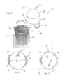
FIG. 1 is a perspective view of a first exemplary universal lid of the present disclosure showing a spill-proof mouthpiece suitable for liquid applications for children, the lid is shown exploded from a container; -
FIG. 2 is a top view of the first exemplary lid ofFIG. 1 ; -
FIG. 3 is a bottom view of the first exemplary lid ofFIG. 1 ; -
FIG. 4 is a front view of the first exemplary lid ofFIG. 1 ; -
FIG. 5 is a side view of the first exemplary lid ofFIG. 1 ; -
FIG. 6 is a cross-sectional view of the first exemplary lid ofFIG. 1 installed on the container ofFIG. 1 ; -
FIG. 7 is a perspective view of a second exemplary lid of the present disclosure showing a spill-proof mouthpiece with a leak-proof seal feature near a closed position, more suitable for adult use; -
FIG. 8 is a perspective view of the second exemplary lid ofFIG. 6 with the seal feature in an open position; -
FIG. 9 is a side view of the second exemplary lid ofFIG. 6 ; -
FIG. 10 is a perspective view of a third exemplary lid of the present disclosure showing the lid on a container; -
FIG. 11 is a perspective view of a fourth exemplary lid of the present disclosure showing a spill-proof access point suitable for liquid applications for adult use; -
FIG. 12 is a top view of the fourth exemplary lid ofFIG. 11 ; -
FIG. 13 is a front view of the fourth exemplary lid ofFIG. 11 ; -
FIG. 14 is a cross-sectional view of the fourth exemplary lid along line 14-14 ofFIG. 13 ; -
FIG. 15 is a front, perspective view of a fifth exemplary lid of the present disclosure showing a spill-proof access point suitable for liquid applications for children; -
FIG. 16 is a rear, perspective view of the fifth exemplary lid ofFIG. 15 ; -
FIG. 17 is a cross-sectional view of the fifth exemplary lid ofFIG. 15 along line 17-17 ofFIG. 16 , with the lid shown in an original state; -
FIG. 18 is a cross-sectional view of two fifth exemplary lids ofFIG. 15 shown in a folded state and stacked, where an alternative vent is shown; -
FIG. 19 is a cross-sectional view of the fifth exemplary lid ofFIG. 15 along line 19-19 ofFIG. 16 , with the lid shown in an original state; -
FIG. 20 is a side, perspective view of the fifth exemplary lid ofFIG. 15 shown in use; -
FIGS. 21-22 are perspective views of a sixth exemplary lid of the present disclosure showing a spill-proof access point suitable for liquid applications for children, where the lid is connected to two different containers; -
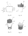
FIG. 23 is a perspective view of a seventh exemplary lid of the present disclosure showing a spill-proof access point suitable for liquid applications for children, where the spout is in an open position; -
FIG. 24 is a cross-sectional view of the seventh exemplary lid ofFIG. 23 along line 24-24 thereof; -
FIG. 25 is a perspective view of the seventh exemplary lid ofFIG. 23 , where the spout is in a closed or folded position; -
FIG. 26 is a perspective view of a eighth exemplary lid of the present disclosure showing a spill-proof access point suitable for liquid applications for children, where a strap and a spout are in an open position; -
FIG. 27 is a perspective view of the eighth exemplary lid ofFIG. 26 , where the strap is in a closed position; -
FIG. 28 is a perspective view of the eighth exemplary lid ofFIG. 26 , where the strap and spout are in a closed position; -
FIG. 29 is a perspective view of a ninth exemplary lid of the present disclosure showing a spill-proof access point suitable for liquid applications for children; -
FIG. 30 is a partial, cross-sectional view of the ninth exemplary lid ofFIG. 29 ; -
FIG. 31 is a side view of the ninth exemplary lid ofFIG. 29 , with the lid shown in an original state; -
FIG. 32 is a cross-sectional view of the ninth exemplary lid ofFIG. 29 shown in a folded state, where an alternative vent is shown; -
FIG. 33 cross-sectional view of the ninth exemplary lid ofFIG. 29 in use; -
FIGS. 34-35 are perspective views of the ninth exemplary lid ofFIG. 29 in use on two different sized containers; -
FIG. 36 is a front, perspective view of a tenth exemplary lid of the present disclosure showing a spill-proof access point suitable for liquid applications for children, the lid is shown in use on a container; -
FIG. 37 is a rear, perspective view of the tenth exemplary lid ofFIG. 36 ; -
FIG. 38 is a cross-sectional view of the tenth exemplary lid ofFIG. 36 ; -
FIG. 39 is a perspective view of the tenth exemplary lid ofFIG. 36 in use with a carrying case adjacent thereto; -
FIG. 40 is a perspective view of an eleventh exemplary lid of the present disclosure showing a spill-proof access point suitable for food applications; -
FIG. 41 is a rear view of the eleventh exemplary lid ofFIG. 40 ; -
FIG. 42 is a partial, cross-sectional, side view of the eleventh exemplary lid ofFIG. 41 along line 42-42 thereof and showing the lid installed on a bowl; -
FIG. 43 is a bottom view of the eleventh exemplary lid ofFIG. 40 ; -
FIG. 44 is a perspective view of a twelfth exemplary lid of the present disclosure showing a spill-proof access point suitable for food applications; -
FIG. 45 is a top, perspective view of a thirteenth exemplary lid of the present disclosure showing a spill-proof access point suitable for food applications; -
FIG. 46 is a bottom, perspective view of the thirteenth exemplary lid ofFIG. 45 ; -
FIG. 47 is a side view of the thirteenth exemplary lid ofFIG. 45 shown installed on a bowl; and -
FIG. 48 is a cross-sectional view of the thirteenth exemplary lid ofFIG. 47 shown along line 48-48 thereof. - Referring to
FIG. 1 ,universal lid 10 of a first exemplary configuration is shown. During use,lid 10 may be applied to a plurality of containers, cups, or drinking vessels one suchcontainer being container 12.Container 12 includescontainer sidewall 14 defining opening 16 and chamber 18.Container 12 further includeslip 20. Chamber 18 containsliquid 22. Container opening 16 has outer opening diameter DO. - Referring to
FIGS. 1-2 ,lid 10 further includes flexibletop wall 24 with an integrally formed upwardly extending mouthpiece, spout or spoutportion 26.Spout 26 defines elongated channel 27 (shown inFIG. 6 ) and includes spill-proof lid openings oroutlets 28. Although threeopenings 28 are shown, an alternative embodiment may have one, two or more than three openings.Openings 28 may be selectively openable and may be self-sealing due to the configuration and material used. As a result, a user may obtain a fluid 18 fromcontainer 12 fromspout 26. Pressure may be applied to spoutportion 26, in order to openopenings 28. This may be done by a user gently biting down onspout portion 26. Alternatively, a user can apply pressure by sucking onspout portion 26 to openopenings 28. Once the pressure is released,openings 28 automatically close.Spout portion 26 may be designed with the contours of a child's mouth in consideration. - Referring to
FIGS. 1-3 ,lid 10 also includesflexible sidewall 30 extending downwardly from and surroundingtop wall 24 to define chamber 32 (shown inFIG. 3 ) therein with chamber opening 32 a.Chamber 32 and channel 27 are in fluid communication, as shown inFIG. 6 . In an initial state, chamber opening 32 a has a first size and in a second state (shown inFIG. 6 ) chamber opening pa has a second size different from the first size. - Referring again to
FIG. 3 , inner sidewall diameter DS (shown inFIG. 3 ) is less than outer opening diameter DO (seeFIG. 1 ) ofcontainer 12 so that upon applying or installinglid 10 oncontainer 12,top wall 24 and/orsidewall 30 stretch from the initial state to the second state andsidewall 30 is locatedadjacent container sidewall 14 and closes container opening 16. In addition,sidewall 30 applies a compressive force oncontainer 12 to create a first seal (as discussed below). Direction of compressive force F is shown inFIG. 6 , and exists continuously around the circumference ofcontainer 12. - Referring to
FIG. 1 ,sidewall 30 further includesfree edge 34. In the present example,free edge 34 includes a pair of integrally formed, diametrically opposed handles 36. Referring toFIGS. 2-5 , each handle 36 definesopening 38. - Referring again to
FIGS. 1-3 , in the present example,top wall 24 andsidewall 30 may be generally circular in shape. InFIGS. 1-5 ,lid 10 is shown in an unstretched or initial state where chamber opening 32 a has a first size and wherelid 10 has not been installed oncontainer 12. - In an initial state, as shown in
FIG. 5 ,lid 10 may have a tapered shape fromtop wall 24 tofree edge 34. As a result,lid 10 has first diameter D1 greater than second Diameter D2. The least amount of taper may be 3 degrees, however a larger taper may also be used. -
FIGS. 1-5 show lid 10 as it applies to vessels containing liquid. In use, referring toFIG. 1 ,flexible lid 10 is stretched overcontainer 12 so thatmouthpiece 26 is situated over container opening 16 nearlip 20 and container opening has a second size larger than first size. Sides or sidewalls 30 oflid 10 are pulled down the side orsidewall 14 ofcontainer 12 usinghandles 36 untillid 10 becomes “taut” across top ortop wall 24 and “taut” along sides orsidewall 30. “Taut” meanstop wall 24 andsidewall 30 have no slack and as a result are tightly drawn. -
Handles 36, thus, aid in pullinglid 10 ontocontainer 12. Whenlid 10 is in the stretched state, sidewall 30 of lid compresses againstsidewall 14 ofcontainer 12. As shown inFIG. 6 , seal 40 is thus created betweencontainer sidewall 14 andlid sidewall 30. As a result, vessel orcontainer 12 can now be tipped over or held upside down without the fear ofliquid 22 pouring out. First seal is strong enough to remain secure upon inversion (or turningcontainer 12 completely upside down when the container contains some liquid or is completely full. - This same method is followed regardless of the size of container opening DO (See
FIG. 1 ), provided it falls within the required range for thatexemplary lid 10. Eachexemplary lid 10 is designed to fit a size range ofcontainers 12 appropriate to its function. - The sizing of
lid 10 inFIG. 1 toFIG. 5 is sufficient to work on the vast majority of drinking vessels that a user may have available. The vessels of various sizes may have opening diameter DO of 60 mm (2 23/64 inches) to 90 mm (3 35/64 inches).Lid 10 may have a first size or sidewall less than about 60 mm and may stretch to a second size to accommodate an opening diameter DO of 95 mm thus difference between the first and second sizes may be at least about 30 mm. However, the present invention is not limited to the present size and if used with larger or smaller containers the size oflid 10 can be adjusted to accommodate other size ranges of containers. -
Lid 10 maybe easily removed fromcontainer 12 by stretching and removinglid 10 from therefrom. Then,container 12 can be refilled, cleaned or the like. When additional consumption of the liquid may be desired,lid 10 may be replaced again on the same or a different container. - The resilient nature of the
material forming lid 10 as well as sidewall diameter DS of lid (seeFIG. 3 ) in the unstretched state being smaller than outer diameter DO of the container used therewith, allowslid 10 to exert a compressive force oncontainer 12 and securely connectslid 10 withcontainer 12 and allowslid 10 to remain thereon until it is removed. -
Lid 10 and spout 26 are molded into an elastic, relatively rigid predetermined shape. As a result,lid 10 and spout 26 are sufficiently rigid to maintain their shape and elastic so that they return to their original shape upon release. - Referring to
FIGS. 7-9 , secondexemplary lid 110 is shown.Lid 110 is similar tolid 10 ofFIG. 1 in that it is tapered.Lid 110 is different fromlid 10 in thatlid 110 is configured for use by an adult. Referring toFIG. 7 ,lid 110 includestop wall 124 with integrally formed central portion 124 a,intermediate portion 124 b, andexterior portion 124 c. Intermediate portion 120 extends at an angle with respect to central portion 124 a thereabout.Intermediate portion 124 b andexterior portion 124 c form mouthpiece or spout portion 126. Spout portion 126 defines opening 128. Spout portion 126 may be designed with the contours of an adult's mouth in consideration. Opening 128 andlid 110 may reduce splashing of a liquid from a cup. - Referring to
FIG. 7 toFIG. 9 ,lid 110 includes spill-proof feature 129 including prongs 129 a, flexible arm 129 b and stopper 129 c. Movable stopper 129 c may selectively open and close opening 128. Prongs 129 a are configured and dimensioned to secure arm 129 b therebetween to hold spill-proof feature 129 in an open position (as shown inFIG. 7 ). Stopper 129 c and opening 128 are configured and dimensioned so that in its closed position, stopper 129 c may be secured within opening or drinking hole 128 and prevents spilling and leaking of liquid therefrom. As a result, a spill-proof seal may created when stopper 129 c is installed in opening 128. In addition, in the closed position feature 129 acts to trap in heat from hot liquids so that they may remain hot for longer. - Referring to
FIGS. 1 and 10 , sidewall 130 oflid 110 may have a tapered shape so that the front has first length L1 less than rear second length L2. Sidewall 130 further includes free edge 134 that includes cutout feature 135 to helplid 110 fit around handle H (seeFIG. 10 ) of mug 212 (seeFIG. 10 ). -
Lid 110 may be sufficiently sized to cover the range of drinking vessel sizes that an adult would expect to drink from. This lid size may accommodate opening diameter DO (seeFIG. 1 ) of about 65 mm (2 9/16 inches) to about 100 mm (3 15/16 inches). Thus, in this example the first size may be less than about 65 mm and the second size may accommodate opening diameter DO of about 100 mm and the difference may be 35 mm. - This embodiment is applied in the same way as stated above with respect to
lid 10. By stretchinglid 110 over vessel 112 (shown inFIG. 10 ) and pulling it all the way down sides 114 of vessel 112 to create a spill-proof seal therewith (as previously discussed).Lid 110 can be used on a variety or plurality of containers of different sizes, as previously discussed with respect tolid 10. - Referring to
FIG. 10 , thirdexemplary lid 110′ is shown.Lid 110′ is similar tolid 110 ofFIG. 6 exceptlid 110′ does not include cutout 135 (shown inFIG. 9 ).Lid 110′ is show on container 112′ with handle H. - Referring to
FIGS. 11-14 , fourthexemplary lid 210 is shown.Lid 210 is similar tolid 110 ofFIG. 1 and is configured for use with an adult. Except spill-proof feature 229 may be configured differently. Spill-proof feature 229 includessecurement recess 229 a,stopper 229 b, andclosure recess 229 c. When feature is in a fully open position,stopper 229 b is withinsecurement recess 229 a andstopper 229 b andrecess 229 c are configured and dimensioned to holdstopper 229 b withinrecess 229 c. When feature 229 is moved to a closed position,stopper 229 b is withinclosure recess 229 c and these features are configured and dimensioned to holdstopper 229 b therein in a spill-proof manner and sealopening 228. -
Lid 210 is also different fromlid 110 in that top wall 224 includes central portion 224 a and roundedexterior portion 224 b. Furthermore,lid 210 includessidewall 230 with thickened area orrim 235.Rim 235 allows a user to more easily grasplid 210 for removal thereof. - This embodiment is applied in the same way as stated above with respect to
lid 10. By stretchinglid 210 over a vessel and pulling it all the way down sides 114 of vessel 112 to create a spill-proof seal therewith (as previously discussed).Lid 210 can be used on a variety of container of different sizes as previously discussed with respect tolid 10. - Referring to
FIGS. 15-17 , fifthexemplary lid 310 is shown.Lid 310 is similar tolid 10 ofFIG. 1 exceptlid 310 does not include handles 36 (shown inFIG. 1 ) and spout portion 326 has a different shape from spout portion 26 (shown inFIG. 1 ). Spout portion 326 oflid 310 may be formed of the same material as the rest oftop wall 324 or spout portion 326 may be formed of a different material as the rest oftop wall 324. For example, spout portion 326 may be formed of a harder, bite-proof second material and remainder oftop wall 324 formed of a softer first material. The first and second materials can be silicones with different hardness values co-molded together, for example. - Referring to
FIGS. 17-19 , in addition,lid 310 includessidewall 330 with upper section 330 a andlower section 330 b joined byhinge section 330 c. Upper section 330 a andlower section 330 b have first thickness t1 and hingesection 330 c has second thickness t2, where second thickness t2 is less than first thickness t1. As a result, when upward and inward forces F (shown inFIG. 17 ) are applied tolower section 330 b,hinge section 330 c allowslower section 330 b to fold into upper section 330 a in to a folded position. As a result, the size oflid 310 is reduced for storage and transport. Once folded,lid 310 can be stacked on anotherlid 310′ in a nested arrangement as shown inFIG. 18 . To unfoldlid 310, a force opposite to force F is applied tolower section 330 b to remove it from upper section 330 a. - Referring to
FIGS. 15 and 17 ,top wall 324 includesvent opening 325.Vent opening 325 may have a funnel shape so that it is larger at the top and decreases in diameter downwardly.Vent opening 325 aids in allowing liquid to be sucked out of container 312 (shown inFIG. 20 ). - In addition,
sidewall 330 oflid 310 may include a thickenedrim 334 that may include an outwardly extending projection 324 a. If a container withlid 310 thereon is knocked over, roll-stop projection 324 a preventslid 310 from rolling. Thus, potentially preventinglid 310 and cup attached thereto from rolling off a surface, for example a table. In an alternative example, lid may include more than roll-stop one projection 324 a. For example, two or more spaced apart projections may be used or a series of tabs, bumps or shaped edges may be used as roll-stops. - In an initial state (as shown in
FIG. 17 ),lid 310 is also tapered, however the taper is greater than that oflid 10.Lid 310 may have a taper where first diameter D1 atfree edge 334 is over 25% narrower than second diameter D2 attop wall 324. The lid may be about 35% narrower at the bottom than at the top. - This embodiment is applied in the same way as stated above with respect to
lid 10. Referring toFIG. 20 , by stretchinglid 310 over vessel 312 (in the unfolded state) and pulling it all the way down thesides 314 of vessel 312 to create a spill-proof seal therewith (as previously discussed).Lid 310 may be used on a variety of containers of different sizes as previously discussed with respect tolid 10. - Referring to
FIGS. 21-22 , sixthexemplary lid 410 is shown.Lid 410 is similar tolid 10 ofFIG. 1 exceptlid 410 does not includehandles 36 with openings 38 (shown inFIG. 1 ), but includestabs 436 for assisting in pullinglid 410 ontocontainers 412 and 413. Furthermore,lid 410 has spout portion 426 with a different shape from spout portion 26 (shown inFIG. 1 ), but similar to mouthpiece 326 (shown inFIG. 54 ). - In
FIGS. 21 and 22 ,lid 410 is shown in use stretched overcontainers 412 and 413.Container 412 has one opening diameter DO (seeFIG. 1 ). InFIG. 22 , container 413 has opening diameter DO (seeFIG. 1 ) different fromcontainer 412. In addition,containers 412 and 313 have different overall shapes, heights and materials.Lid 410 may be used likelid 10. - Referring to
FIGS. 23-25 , seventhexemplary lid 510 is shown.Lid 510 is similar tolid 410 ofFIG. 21 exceptlid 510 includes chamber 511 defined adjacent sidewall 530 and integrally formed therewith. Furthermore, spout portion 526 is configured and dimensioned to be bendable so that when not in use spout portion 526 can be disposed within chamber 511 (as shown inFIG. 25 ) so that spout portion 526 remains clean. Spout portion 526 is shown in the folded or stored position inFIG. 25 and in the in use position inFIGS. 23 and 24 .Lid 510 may be applied to a container likelid 10. - Referring to
FIGS. 26-28 , eighthexemplary lid 610 is shown.Lid 610 is similar tolid 410 ofFIG. 21 exceptlid 610 includes notch 611 andchannel 631 defined withinsidewall 630. Furthermore,sidewall 630 includes integrally formedstrap 632.Channel 631 receivesstrap 632 and assists in securingstrap 632 in position onlid 610.Strap 632 further includes opening 632 a defined therein and workingend portion 633 defining a series of spaced apart paired projections 633 a, 633 b, 633 c, 633 d. Whenstrap 632 is secured aroundlid 610 as shown inFIG. 227 , opening 632 a and projections 633 b are configured and dimensioned to securestrap 632 aboutlid 610. This aids in securinglid 610 to a container (not shown) by increasing the dexterity and force necessary to removelid 610. Thus, a child may find removal oflid 610 more difficult. - In
lid 610, spout portion 626 may be configured in a cylinder and dimensioned to be bendable so that when not in use spout portion 626 can be disposed within groove 611 (as shown inFIG. 28 ) so that it may be spill-proof when not in use. In the in-use position (seeFIG. 27 ), spout portion 626 allows liquid to flow therethrough. Applying oflid 610 to various containers is similar tolid 10. - Referring to
FIGS. 29-31 , ninthexemplary lid 710 is shown.Lid 710 is similar tolid 310 ofFIG. 15 and includes hinge section 730 c as part of sidewall 730. As a result,lid 710 can be used in an unfolded state, as shown inFIGS. 29-31 and stored in a folded state, as shown inFIG. 32 .Lid 710 may be folded and stacked as previously discussed with respect tolid 310. Changinglid 810 from unfolded or original state to the folded state and vice versa is accomplished as discussed with respect tolid 310.Lid 710 further includes funnel-shaped vent 725 similar to vent 325. -
Lid 710 is different fromlid 310 in that it lacks a spout portion like spout portion 326 and includes opening 728 suitable for use with straw S (seeFIG. 33 ). Furthermore,lid 710 is shaped to have a continuous radius of curvature between the sidewall 730 and top wall 724 (as seen inFIG. 33 ). - In
FIGS. 34-35 ,lid 710 is shown in-use, stretched over containers 712 and 713. Container 712 has one opening diameter DO. (seeFIG. 1 ). InFIG. 35 , container 713 has opening diameter DO (seeFIG. 1 ) different fromcontainer 812. In addition, containers 712 and 713 have different overall shapes, heights and materials. Use and sealing oflid 710 to a container is similar tolid 210. - Referring to
FIG. 33 , when a user inserts straw S into opening 728,lid 710 creates second seal S2 about straw S. As a result, opening 728 becomes a spill-proof opening. Thus, spill-proof first seal is formed between sidewall 730 oflid 710 and container 712 or 713 (as previously discussed with respect to lid 10) and second spill-proof seal S2 is created betweenlid 710 and straw S. - Referring to
FIGS. 36-38 , tenthexemplary lid 810 is shown.Lid 810 similar tolid 310 ofFIG. 15 , exceptlid 810 includesdifferent spout portion 826. Top wall 824 is formed of two different materials. Thespout portion 826 includes first layer 827 a of soft material and co-molded second outer layer 827 b of a harder material. First layer 827 a includes slit 828 a aligned with larger opening 828 b defined in second layer 828 b. When a user sucks liquid out oflid 810, the pressure causes slit 827 a to selectively open allowing liquid to flow out of opening 828 b. When the pressure is released, slit 827 a automatically closes makinglid 810 spill-proof. Alternatively,spout portion 826 may be formed of a single layer of material substantially more rigid than remainder oflid 810, this allowsmouthpiece 826 to be bite proof. -
Spout portion 826 may have a figurative or decorative shape, such as for example, an animal shape.Lid 810 shows exemplary teddy bear (as shown) shapedspout 826. Furthermore,mouthpiece 826 and remainder oflid 810 may be of different colors. InFIGS. 38 ,lid 810 is shown in use stretched overcontainer 812. Applying oflid 810 tocontainer 812 is similar tolid 310. -
Lid 810 may include a hinge section similar tolid 310. When in a foldedposition lid 810 may be stored in a carrying case C (shown inFIG. 39 ). Carrying case C may be used with various lids and sized to contain the lid for clean transport and storage. Carrying case is formed using conventional manufacturing methods and may include a living hinge and a snap fit. Carrying case C may be formed to have a decorative shape C′.Lid 810 may also include a roll-stop projection as previously discussed. - Referring to
FIGS. 40-42 , eleventhexemplary lid 910 is shown.Lid 910 is similar tolid 10 ofFIG. 1 exceptlid 910 is configured for use with container 912 that contains food F. Referring toFIG. 40 ,lid 910 includestop wall 924 with a self-sealing spill-proof opening 928 in the form of elongated slit 929.Top wall 924 includes two overlapping movable flaps 924 a and 924 b. When a user's hand (not shown) is inserted into slit 929, flaps 924 a and 924 b move to an open state to allow access to food F. When the hand is removed, flaps 924 a and 924 b return to their initial state and food F cannot be spilled from container 912. Opening 928 may be sized to fit a child's hand therethrough. - Sidewall 930 may include integral handle 936 defining opening 938. Handle 936 assists in pulling
lid 910 onto container 912. Handle 936 also allows the child to easily hold and carry vessel 912 around. - Sidewall 930 further includes
free edge 934. In the present embodiment,free edge 934 may be shaped so that sidewall 930 has first length L1 at the front greater than second length L2 at the rear. In an alternative example, first and second lengths L1 and L2 may be substantially the same. - Furthermore,
free edge 934 further includes strap 934 a extending across lid 910 (as best shown inFIG. 43 ). Strap 934 a may be flexible, and when installed onto container as shown inFIG. 45 applies an upward force on container 912 to helpsecure lid 910 thereon. Strap 934 a may be used to offer additional securement oflid 910 to vessel 912. In an alternative,example lid 910 may not include strap 934 a or may include strap, which has a different shape such as a cross-shape. -
Lid 910 may be applied in the same way as stated above with respect tolid 10. By stretchinglid 910 over vessel 912 (shown inFIG. 40 ) and pulling it all the way down the sides 914 of vessel 912 untillid 910 becomes taut across top 1024 and taut alongside sidewall 930 (seeFIGS. 42 ). As a result,lid 910 and vessel 921 have a spill-proof connection, as previously discussed with respect tolid 10. - In
FIG. 41-45 lid 910 is sufficiently sized to fit a range of vessels that a child might be expected to hold with one hand while accessing the contents with the other hand. Such vessels may have an opening diameter of 90 mm (3 15/16 inches to 125 mm (4 59/64 inches), which is a difference of about 35 mm. - Referring to
FIG. 44 , twelfthexemplary lid 1010 is shown.Lid 1010 is similar tolid 910 ofFIG. 40 exceptlid 1010 has elongated slit 1028 without flaps 924 a and 924 b ofFIG. 40 .Slit 1028 may be self-sealing.Lid 1010 may be applied to a variety of containers likelid 910. - Referring to
FIGS. 45 and 46 , thirteenthexemplary lid 1110 is shown.Lid 1110 is similar tolid 910 ofFIG. 40 exceptlid 1110 has different shapedopening 1128 for accessing food within a container andstrap 1129 has buckle feature 1129 a for installing and removal. Buckle feature 1129 a allowsstrap 1129 to be adjustable. -
Opening 1128 may have a generally cruciate or cross-shape, however other shapes may be used. In addition, opening 1128 has a funnel shape so that it tapers from a wider width at the top to the more narrow width at the bottom. This allows access to the contents but keeps the contents of the bowl inside when the bowl is inverted. Upon inversion (as shown inFIGS. 47 and 48 ), food F falls around the perimeter of the funneled opening 128.Lid 1110 may be applied to a variety of containers likelid 910. -
Lids Covers - In some embodiments such as lid 810 (shown in
FIG. 32 ), certain features likemouthpiece 826 may require a harder, stiffer material. An example might be plastics such as Polypropylene or Polyethylene, silicones with a harder durometer, rubbers of a harder durometer, the synthetic polymers sold under the trademark NYLON®, Acrylonitrile Styrene, Acrylonitrile Butadiene Styrene, the copolyester sold under the trademark Triton™, Polycarbonite. It may also be necessary in some embodiments likelid 810 to co-mold the soft plastic of the lid with a hard plastic of a feature in order to benefit from the properties of both. - Those skilled in the art will appreciate that the conception, upon which this disclosure is based, may readily be utilized as a basis for designing other products. Therefore, the claims are not to be limited to the specific examples depicted herein. For example, the features of one example disclosed above may be used with the features of another example. For example, the downwardly tapered sidewall may be incorporated any of the examples. For example, the hinge may be incorporated into other examples. The integrally formed handle(s) may be formed in other examples. For example, the roll-stop projection may be used on other lids. For example, lids may have all or some combination of downwardly tapered sidewall, hinge, rim, vent hole, handles, roll-stop projection, and/or securing strap. Lids of each exemplary configuration may be formed in a variety of sizes and depths, so that they can be used with a variety of containers. Thus, the details of these components as set forth in the above-described examples, should not limit the scope of the claims.
- Further, the purpose of the Abstract is to enable the U. S. Patent and Trademark Office, and the public generally, and especially the scientists, engineers and practitioners in the art who are not familiar with patent or legal terms or phraseology, to determine quickly from a cursory inspection the nature and essence of the technical disclosure of the application. The Abstract is neither intended to define the claims of the application nor is intended to be limiting on the claims in any way.
Claims (22)
Priority Applications (1)
| Application Number | Priority Date | Filing Date | Title |
|---|---|---|---|
| US14/779,396 US9848721B2 (en) | 2013-03-24 | 2014-03-24 | Universal lid for food and drink containers |
Applications Claiming Priority (3)
| Application Number | Priority Date | Filing Date | Title |
|---|---|---|---|
| US201361804714P | 2013-03-24 | 2013-03-24 | |
| PCT/US2014/031582 WO2014160642A1 (en) | 2013-03-24 | 2014-03-24 | Universal lid for food and drink containers |
| US14/779,396 US9848721B2 (en) | 2013-03-24 | 2014-03-24 | Universal lid for food and drink containers |
Publications (2)
| Publication Number | Publication Date |
|---|---|
| US20160051069A1 true US20160051069A1 (en) | 2016-02-25 |
| US9848721B2 US9848721B2 (en) | 2017-12-26 |
Family
ID=51625469
Family Applications (1)
| Application Number | Title | Priority Date | Filing Date |
|---|---|---|---|
| US14/779,396 Active US9848721B2 (en) | 2013-03-24 | 2014-03-24 | Universal lid for food and drink containers |
Country Status (2)
| Country | Link |
|---|---|
| US (1) | US9848721B2 (en) |
| WO (1) | WO2014160642A1 (en) |
Cited By (6)
| Publication number | Priority date | Publication date | Assignee | Title |
|---|---|---|---|---|
| US9848722B1 (en) | 2016-12-31 | 2017-12-26 | John J. Lopynski | Container assembly with a lid and the lid thereof that allow for drinking from the side |
| US20180177315A1 (en) * | 2016-12-27 | 2018-06-28 | Betty Thrasher | Drinking Container Lid Device |
| USD838167S1 (en) | 2017-09-12 | 2019-01-15 | John J. Lopynski | Lid for beverage container |
| US10251499B2 (en) | 2016-12-31 | 2019-04-09 | John J. Lopynski | Container assembly with a lid and the lid thereof that allow for drinking from the side |
| US10780405B2 (en) * | 2017-07-10 | 2020-09-22 | Wine Accents, LLC | Liquid dispensing and aerating system |
| US20230159231A1 (en) * | 2021-11-19 | 2023-05-25 | Ceres Chill, Inc. | Drinking and sealing lids for vessels and associated devices and methods |
Families Citing this family (12)
| Publication number | Priority date | Publication date | Assignee | Title |
|---|---|---|---|---|
| US9782029B1 (en) | 2013-04-30 | 2017-10-10 | Corytus, Llc | Lid and method of using a lid |
| EP3172141B1 (en) | 2014-07-25 | 2019-06-12 | Corytus LLC | A lid and method of using a lid |
| DE102014119031A1 (en) * | 2014-12-18 | 2016-06-23 | Villeroy & Boch Ag | Tableware and method of making tableware |
| US10220984B1 (en) | 2015-04-10 | 2019-03-05 | Matthew M. Vigoureux | Universal container lid |
| WO2018191175A1 (en) * | 2017-04-10 | 2018-10-18 | Robell Kevin | Methods and materials for prolonging plant viability in refrigeration-free storage environments |
| DE102019106312B4 (en) | 2019-03-12 | 2021-01-21 | Stefan Graf | Baby bottle attachment |
| US11518583B2 (en) | 2019-12-04 | 2022-12-06 | California Innovations Inc. | Container assembly |
| TWI711566B (en) * | 2020-02-13 | 2020-12-01 | 段睿紘 | Cover structure |
| CN112340221B (en) * | 2020-11-11 | 2022-09-13 | 浙江舒康科技有限公司 | Cold and hot pulp cup cover with folding plug, container assembly and using method |
| TWD219250S (en) * | 2020-11-24 | 2022-06-11 | 美商繆詩有限公司 | Snack cup |
| US11344478B1 (en) * | 2020-11-26 | 2022-05-31 | Natara Matias | Baby bottle cover |
| USD1014192S1 (en) * | 2021-11-15 | 2024-02-13 | Xiamen Newtop Material Company | Multifunction silicone cup |
Citations (17)
| Publication number | Priority date | Publication date | Assignee | Title |
|---|---|---|---|---|
| US2266270A (en) * | 1938-10-20 | 1941-12-16 | Adam G Roth | Closure means |
| US2443560A (en) * | 1946-04-09 | 1948-06-15 | Seamless Rubber Co | Nursing nipple |
| US2569139A (en) * | 1948-07-07 | 1951-09-25 | Abelson Herman | Weaning cap for nursing bottles |
| US2693187A (en) * | 1952-04-25 | 1954-11-02 | Davol Rubber Co | Vented nipple construction |
| US2839229A (en) * | 1955-06-14 | 1958-06-17 | Crown Cork & Seal Co | Seamed metal container with plastic cover for the seam and plastic pouring spout |
| US4901881A (en) * | 1987-10-09 | 1990-02-20 | Mcelroy Steven G | Method and apparatus for closing containers |
| US5036994A (en) * | 1988-09-12 | 1991-08-06 | Mcelroy Steven G | Integrated container/lid assembly |
| US5474028A (en) * | 1994-01-25 | 1995-12-12 | Merrick's, Inc. | Animal feeding nipple |
| US5769285A (en) * | 1996-02-20 | 1998-06-23 | Veterinarian's Outlet Inc. | Calf nipple |
| US5797505A (en) * | 1996-05-31 | 1998-08-25 | Kaura; Kam | Debris immune animal feeding nipple |
| US7134564B2 (en) * | 2003-10-16 | 2006-11-14 | Verbovszky Esther A L | Beverage bottle cap for child use |
| US20080035665A1 (en) * | 2004-09-08 | 2008-02-14 | Melissa Edmunds | Container Cover and Dispenser Therefor |
| US7678271B2 (en) * | 2007-03-22 | 2010-03-16 | Progressive International Corporation | Collapsible colander and bowl |
| US20100200530A1 (en) * | 2009-02-12 | 2010-08-12 | West Agro Inc. | Nipple For Feeding Liquids To Calves And Other Mammals |
| US20110240589A1 (en) * | 2010-04-02 | 2011-10-06 | Averill Walter J | Reusable resilient bottle capsule |
| US20140061193A1 (en) * | 2012-08-31 | 2014-03-06 | Daniel A. Sudakoff | Collapsible food container |
| US20150359365A1 (en) * | 2014-06-12 | 2015-12-17 | Silikids, Inc. | Universal Lid for Drinking Cups |
Family Cites Families (65)
| Publication number | Priority date | Publication date | Assignee | Title |
|---|---|---|---|---|
| US1243033A (en) | 1916-12-06 | 1917-10-16 | Harry Burroughs Beatty | Detachable cover. |
| US1439170A (en) | 1920-06-23 | 1922-12-19 | Kawasaki Utakichi | Bottle closure |
| US1983139A (en) | 1930-08-30 | 1934-12-04 | Arden Box Toe Company | Container and closure therefor |
| GB370027A (en) | 1930-11-25 | 1932-03-29 | Minnie Rebecca Dod | Improvements in feeding bottles and the like |
| US2003657A (en) | 1934-04-27 | 1935-06-04 | Stubblefield Roy Irvin | Cap for drinking glasses |
| US2064411A (en) | 1936-02-08 | 1936-12-15 | Samuel J Brandstein | Combination bowl and adjustable moisture tight cover therefor |
| US2080108A (en) | 1936-11-21 | 1937-05-11 | Samuel J Brandstein | Cover for containers of different sizes |
| US2199787A (en) | 1938-12-27 | 1940-05-07 | Dillard Horace Oscar | Receptacle cover |
| US2550568A (en) | 1947-02-25 | 1951-04-24 | Ronald C Kersh | Device for weaning infants |
| US2689664A (en) | 1949-12-06 | 1954-09-21 | Vingron Ilona | Cover for drinking glasses, cups, and the like |
| US2530999A (en) | 1949-12-10 | 1950-11-21 | Harold A Schuler | Bottle cap |
| US2608841A (en) | 1950-11-16 | 1952-09-02 | William W Rice | Drinking cup for use by infants and invalids such as chair and bedridden patients |
| US2804242A (en) | 1955-07-07 | 1957-08-27 | John E Borah | Container spout and gasket combination |
| US2905350A (en) | 1957-11-29 | 1959-09-22 | Illinois Tool Works | Cup for hot beverages |
| US3093273A (en) | 1959-07-03 | 1963-06-11 | John E Borah | Retractable and extensible container spout |
| US3207377A (en) | 1963-12-12 | 1965-09-21 | Jerome H Lemelson | Dispensing closure |
| US3434589A (en) | 1967-05-02 | 1969-03-25 | Frank J Valtri | Expandable container |
| US3765048A (en) | 1972-04-26 | 1973-10-16 | L Zakhi | Polish can |
| DE2920159A1 (en) | 1979-05-18 | 1980-11-27 | Wolfgang Dr Ing Meins | DRINKING DEVICE FOR BEVERAGE CAN |
| US4246945A (en) | 1979-11-08 | 1981-01-27 | Medline Industries, Inc. | Hamper hood |
| US4328904A (en) | 1981-02-03 | 1982-05-11 | Iverson Elaine J | Spill proof container and closure |
| JPS60240634A (en) | 1984-05-08 | 1985-11-29 | 関 則雄 | Cup which can easily be drunk up |
| US4542833A (en) | 1984-06-11 | 1985-09-24 | Bio-Plas, Inc. | Stretchable cap for sealing and/or resealing blood drawing tubes and the like |
| US4640855A (en) | 1985-10-25 | 1987-02-03 | Owens-Illinois, Inc. | Plastic container with integral spout |
| US4815628A (en) | 1988-06-27 | 1989-03-28 | Wehnert Iii Arthur R | Container sealer |
| US5186347A (en) | 1991-10-15 | 1993-02-16 | Freeman Mark A | Spill-proof closure |
| US5586681A (en) | 1993-03-11 | 1996-12-24 | Policappelli; Nini E. | Container for dispensing liquids |
| US5762230A (en) | 1993-03-11 | 1998-06-09 | Policappelli; Nini | Laminated container |
| US6354458B1 (en) | 1993-03-11 | 2002-03-12 | Nini Policappelli | Top for container |
| USD364314S (en) | 1993-09-28 | 1995-11-21 | Gerber Products Company | Drinking cup for children |
| US5370253A (en) | 1994-04-08 | 1994-12-06 | Kite; Lewis D. | Disposable cap |
| US5816428A (en) | 1994-09-28 | 1998-10-06 | The Coca-Cola Company | Easy-open can end and spout |
| USD398813S (en) | 1997-04-25 | 1998-09-29 | Bottoms Up, Inc. | Attachment for beverage containers |
| US5988425A (en) | 1998-01-19 | 1999-11-23 | Yehl; Gregory | Sipper cup |
| US6112926A (en) | 1998-03-18 | 2000-09-05 | Fishman; Gary Lee | Non-closable threaded drink-through spout cap for common beverage bottles |
| US6609630B1 (en) | 1999-04-22 | 2003-08-26 | Mark A. Freeman | Leak-proof closure apparatus |
| USD430455S (en) | 1999-05-13 | 2000-09-05 | Lucuis J Pickens | Combined sipper cap and flow control disc |
| US6260731B1 (en) | 1999-09-10 | 2001-07-17 | Tony P. Cummings | Lid and clip combination for child's cup |
| US6305584B1 (en) * | 1999-10-07 | 2001-10-23 | Branco Dobobrov | Dispensing cover assembly |
| US6176384B1 (en) | 2000-01-20 | 2001-01-23 | Corri Voloshin | Spill-proof snack container |
| USD436539S1 (en) | 2000-05-11 | 2001-01-23 | Lacrad International Corporation | Container having a collapsible cap |
| US20020158075A1 (en) | 2001-03-26 | 2002-10-31 | Caldicott Robert John | One material, one piece spill-proof closure |
| US8302798B2 (en) | 2001-09-04 | 2012-11-06 | Moss Christine K | Anti-spill container |
| USD479946S1 (en) | 2001-09-28 | 2003-09-30 | Dart Industries Inc. | Child's sipper lid with fluted dome |
| US6976604B2 (en) | 2001-10-05 | 2005-12-20 | The First Years Inc. | Restricting flow in drinking containers |
| US20040000551A1 (en) | 2002-06-26 | 2004-01-01 | Flink Christopher M. | Trainer cup adapter lid for a beverage can |
| US6877626B2 (en) | 2002-12-30 | 2005-04-12 | Joseph Sherrod | Spill proof cap for different sized bottle openings |
| US6883677B2 (en) | 2003-03-28 | 2005-04-26 | Fort James Corporation | Disposable drinking device |
| US7318534B2 (en) | 2003-06-13 | 2008-01-15 | S.C. Johnson Home Storage, Inc. | Disposable container cover with elastic replacement |
| US7654402B2 (en) | 2003-12-16 | 2010-02-02 | Dart Industries Inc. | Collapsible container |
| US20060131308A1 (en) | 2004-12-08 | 2006-06-22 | Drake Devin J | Can cap |
| US8317046B2 (en) | 2008-12-11 | 2012-11-27 | M & C Innovations, Llc | Collapsible coolers |
| US7854336B2 (en) | 2005-07-05 | 2010-12-21 | Jordan Kerner | Beverage dispenser having an airtight valve and seal |
| USD545137S1 (en) | 2005-09-23 | 2007-06-26 | Rubbermaid Incorporated | Collapsible storage container |
| US20070090081A1 (en) * | 2005-10-25 | 2007-04-26 | Dylan Briscoe | Flexible drinking lid |
| US20100012670A1 (en) | 2008-07-21 | 2010-01-21 | Mark Massey | Dispensing lid for container |
| US8844764B2 (en) | 2009-02-11 | 2014-09-30 | Progressive International Corporation | Baked goods carrier |
| US8123885B2 (en) | 2009-02-17 | 2012-02-28 | Covermate, Inc. | Method of manufacturing flexible covers |
| USD616249S1 (en) | 2009-06-09 | 2010-05-25 | Chelsea And Scott, Ltd. | Non-spill container |
| US8256642B2 (en) | 2009-09-10 | 2012-09-04 | Helen Of Troy Limited | Sippy cup assembly |
| WO2011066220A2 (en) | 2009-11-30 | 2011-06-03 | Stern R Gabriel | Storage container system including universal lids |
| KR20120030671A (en) * | 2010-09-20 | 2012-03-29 | 전명성 | Straw assembly |
| US20120145727A1 (en) | 2010-12-08 | 2012-06-14 | Kevin Coy Gammage | Cover |
| US9295350B2 (en) | 2012-09-10 | 2016-03-29 | Mattel, Inc. | Sippy cup soft spout and method of forming the same |
| US9221582B2 (en) | 2013-09-25 | 2015-12-29 | Lifetime Brands, Inc. | Collapsible container |
-
2014
- 2014-03-24 WO PCT/US2014/031582 patent/WO2014160642A1/en active Application Filing
- 2014-03-24 US US14/779,396 patent/US9848721B2/en active Active
Patent Citations (17)
| Publication number | Priority date | Publication date | Assignee | Title |
|---|---|---|---|---|
| US2266270A (en) * | 1938-10-20 | 1941-12-16 | Adam G Roth | Closure means |
| US2443560A (en) * | 1946-04-09 | 1948-06-15 | Seamless Rubber Co | Nursing nipple |
| US2569139A (en) * | 1948-07-07 | 1951-09-25 | Abelson Herman | Weaning cap for nursing bottles |
| US2693187A (en) * | 1952-04-25 | 1954-11-02 | Davol Rubber Co | Vented nipple construction |
| US2839229A (en) * | 1955-06-14 | 1958-06-17 | Crown Cork & Seal Co | Seamed metal container with plastic cover for the seam and plastic pouring spout |
| US4901881A (en) * | 1987-10-09 | 1990-02-20 | Mcelroy Steven G | Method and apparatus for closing containers |
| US5036994A (en) * | 1988-09-12 | 1991-08-06 | Mcelroy Steven G | Integrated container/lid assembly |
| US5474028A (en) * | 1994-01-25 | 1995-12-12 | Merrick's, Inc. | Animal feeding nipple |
| US5769285A (en) * | 1996-02-20 | 1998-06-23 | Veterinarian's Outlet Inc. | Calf nipple |
| US5797505A (en) * | 1996-05-31 | 1998-08-25 | Kaura; Kam | Debris immune animal feeding nipple |
| US7134564B2 (en) * | 2003-10-16 | 2006-11-14 | Verbovszky Esther A L | Beverage bottle cap for child use |
| US20080035665A1 (en) * | 2004-09-08 | 2008-02-14 | Melissa Edmunds | Container Cover and Dispenser Therefor |
| US7678271B2 (en) * | 2007-03-22 | 2010-03-16 | Progressive International Corporation | Collapsible colander and bowl |
| US20100200530A1 (en) * | 2009-02-12 | 2010-08-12 | West Agro Inc. | Nipple For Feeding Liquids To Calves And Other Mammals |
| US20110240589A1 (en) * | 2010-04-02 | 2011-10-06 | Averill Walter J | Reusable resilient bottle capsule |
| US20140061193A1 (en) * | 2012-08-31 | 2014-03-06 | Daniel A. Sudakoff | Collapsible food container |
| US20150359365A1 (en) * | 2014-06-12 | 2015-12-17 | Silikids, Inc. | Universal Lid for Drinking Cups |
Cited By (6)
| Publication number | Priority date | Publication date | Assignee | Title |
|---|---|---|---|---|
| US20180177315A1 (en) * | 2016-12-27 | 2018-06-28 | Betty Thrasher | Drinking Container Lid Device |
| US9848722B1 (en) | 2016-12-31 | 2017-12-26 | John J. Lopynski | Container assembly with a lid and the lid thereof that allow for drinking from the side |
| US10251499B2 (en) | 2016-12-31 | 2019-04-09 | John J. Lopynski | Container assembly with a lid and the lid thereof that allow for drinking from the side |
| US10780405B2 (en) * | 2017-07-10 | 2020-09-22 | Wine Accents, LLC | Liquid dispensing and aerating system |
| USD838167S1 (en) | 2017-09-12 | 2019-01-15 | John J. Lopynski | Lid for beverage container |
| US20230159231A1 (en) * | 2021-11-19 | 2023-05-25 | Ceres Chill, Inc. | Drinking and sealing lids for vessels and associated devices and methods |
Also Published As
| Publication number | Publication date |
|---|---|
| WO2014160642A1 (en) | 2014-10-02 |
| US9848721B2 (en) | 2017-12-26 |
Similar Documents
| Publication | Publication Date | Title |
|---|---|---|
| US9848721B2 (en) | Universal lid for food and drink containers | |
| US5573139A (en) | Drinking mug with lid and mug body formed from one piece | |
| US10625921B2 (en) | Integrated anti-spill container | |
| JP5199288B2 (en) | Cup assembly | |
| CA2845311C (en) | Spillproof container assemblies | |
| US11937714B2 (en) | Training cup | |
| JP2010521388A (en) | Drinking container | |
| US10364072B2 (en) | Spill proof container | |
| US5893472A (en) | Spout for valve assembly | |
| US11548696B2 (en) | Lid for a container | |
| US8118182B1 (en) | Ergonomic beverage container | |
| US10653255B1 (en) | Container cap with integrated straw | |
| JP4805815B2 (en) | Cup assembly | |
| US20150020906A1 (en) | Non-spill valve | |
| KR200467504Y1 (en) | Multipurpose container with drop preventing function of snack | |
| US10993561B2 (en) | Dispensing fluids from drinking containers | |
| US20200397166A1 (en) | Textured lid for a drinking container | |
| GB2484013A (en) | Non-spill cup with a plurality of sipping apertures | |
| WO2014117209A1 (en) | Drinking container cap with demand valve | |
| US20110272300A1 (en) | Combination spill-proof drink cup and spill-proof food cup | |
| US11465821B1 (en) | Holder for food and beverage containers | |
| US20220061561A1 (en) | Beverage container | |
| WO2013079946A2 (en) | Dispensing container | |
| PH22014000386U1 (en) | An improved trainer cup |
Legal Events
| Date | Code | Title | Description |
|---|---|---|---|
| AS | Assignment |
Owner name: DOUBLE DOUBLE INC., CALIFORNIA Free format text: ASSIGNMENT OF ASSIGNORS INTEREST;ASSIGNORS:TURNER, SATIVA;IVANKOVIC, MICHELLE;REEL/FRAME:033846/0671 Effective date: 20140926 |
|
| AS | Assignment |
Owner name: DOUBLE DOUBLE INC., CALIFORNIA Free format text: ASSIGNMENT OF ASSIGNORS INTEREST;ASSIGNORS:TURNER, SATIVA;IVANKOVIC, MICHELLE;REEL/FRAME:036633/0315 Effective date: 20140926 |
|
| STCF | Information on status: patent grant |
Free format text: PATENTED CASE |
|
| MAFP | Maintenance fee payment |
Free format text: PAYMENT OF MAINTENANCE FEE, 4TH YR, SMALL ENTITY (ORIGINAL EVENT CODE: M2551); ENTITY STATUS OF PATENT OWNER: SMALL ENTITY Year of fee payment: 4 |