US20140118699A1 - Method for Calculating Tear Film Lipid and Aqueous Layer Thicknesses and Corneal Surface Refractive Index from Interferometry Data - Google Patents
Method for Calculating Tear Film Lipid and Aqueous Layer Thicknesses and Corneal Surface Refractive Index from Interferometry Data Download PDFInfo
- Publication number
- US20140118699A1 US20140118699A1 US14/058,564 US201314058564A US2014118699A1 US 20140118699 A1 US20140118699 A1 US 20140118699A1 US 201314058564 A US201314058564 A US 201314058564A US 2014118699 A1 US2014118699 A1 US 2014118699A1
- Authority
- US
- United States
- Prior art keywords
- tear film
- sin
- sqrt
- contact lens
- cos
- Prior art date
- Legal status (The legal status is an assumption and is not a legal conclusion. Google has not performed a legal analysis and makes no representation as to the accuracy of the status listed.)
- Granted
Links
Images
Classifications
-
- A—HUMAN NECESSITIES
- A61—MEDICAL OR VETERINARY SCIENCE; HYGIENE
- A61B—DIAGNOSIS; SURGERY; IDENTIFICATION
- A61B3/00—Apparatus for testing the eyes; Instruments for examining the eyes
- A61B3/10—Objective types, i.e. instruments for examining the eyes independent of the patients' perceptions or reactions
- A61B3/1015—Objective types, i.e. instruments for examining the eyes independent of the patients' perceptions or reactions for wavefront analysis
-
- A—HUMAN NECESSITIES
- A61—MEDICAL OR VETERINARY SCIENCE; HYGIENE
- A61B—DIAGNOSIS; SURGERY; IDENTIFICATION
- A61B3/00—Apparatus for testing the eyes; Instruments for examining the eyes
- A61B3/10—Objective types, i.e. instruments for examining the eyes independent of the patients' perceptions or reactions
- A61B3/101—Objective types, i.e. instruments for examining the eyes independent of the patients' perceptions or reactions for examining the tear film
-
- A—HUMAN NECESSITIES
- A61—MEDICAL OR VETERINARY SCIENCE; HYGIENE
- A61B—DIAGNOSIS; SURGERY; IDENTIFICATION
- A61B3/00—Apparatus for testing the eyes; Instruments for examining the eyes
- A61B3/10—Objective types, i.e. instruments for examining the eyes independent of the patients' perceptions or reactions
- A61B3/103—Objective types, i.e. instruments for examining the eyes independent of the patients' perceptions or reactions for determining refraction, e.g. refractometers, skiascopes
-
- A—HUMAN NECESSITIES
- A61—MEDICAL OR VETERINARY SCIENCE; HYGIENE
- A61B—DIAGNOSIS; SURGERY; IDENTIFICATION
- A61B3/00—Apparatus for testing the eyes; Instruments for examining the eyes
- A61B3/10—Objective types, i.e. instruments for examining the eyes independent of the patients' perceptions or reactions
- A61B3/14—Arrangements specially adapted for eye photography
- A61B3/15—Arrangements specially adapted for eye photography with means for aligning, spacing or blocking spurious reflection ; with means for relaxing
- A61B3/152—Arrangements specially adapted for eye photography with means for aligning, spacing or blocking spurious reflection ; with means for relaxing for aligning
-
- A—HUMAN NECESSITIES
- A61—MEDICAL OR VETERINARY SCIENCE; HYGIENE
- A61F—FILTERS IMPLANTABLE INTO BLOOD VESSELS; PROSTHESES; DEVICES PROVIDING PATENCY TO, OR PREVENTING COLLAPSING OF, TUBULAR STRUCTURES OF THE BODY, e.g. STENTS; ORTHOPAEDIC, NURSING OR CONTRACEPTIVE DEVICES; FOMENTATION; TREATMENT OR PROTECTION OF EYES OR EARS; BANDAGES, DRESSINGS OR ABSORBENT PADS; FIRST-AID KITS
- A61F9/00—Methods or devices for treatment of the eyes; Devices for putting-in contact lenses; Devices to correct squinting; Apparatus to guide the blind; Protective devices for the eyes, carried on the body or in the hand
- A61F9/007—Methods or devices for eye surgery
- A61F9/008—Methods or devices for eye surgery using laser
- A61F2009/00861—Methods or devices for eye surgery using laser adapted for treatment at a particular location
- A61F2009/00872—Cornea
Definitions
- the invention relates to measurement and analysis of the ocular environment.
- Dry eye disease affects approximately 12 million people in the US.
- the integrity of the tear film lipid and aqueous layers is critical for proper tear film function and avoidance of dry eye.
- Wavelength-dependent optical interferometry has been used to simultaneously measure tear film lipid and aqueous layers thicknesses at a single point at the apex of the cornea over a period of time. Such measurements can be used to diagnose sub categories of dry eye from (a) either lipid or aqueous deficiencies, or (b) time-profile changes in lipid and aqueous layer thicknesses after a blink.
- lipid and aqueous layer thicknesses are critical for proper diagnosis of dry eye sub categories. Previous lipid and aqueous layer thickness calculation methods using interferometry data were conducted separately. This was due to the large differences in layer thicknesses (aqueous: 1-5 microns, lipid: 20-120 nanometers), basing aqueous thickness calculations upon spectral interference oscillations and absence of spectral oscillations from the lipid layer.
- the corneal glycocalyx is comprised of transmembrane mucins and the integrity of the corneal glycocalyx is believed to be required for tear film stability and prevention of dry eye. Having such a diagnostic tool would assist researchers in the diagnosis of dry eye and development of compositions which could assist or restore a patient's glycocalyx function.
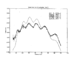
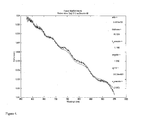
- FIG. 1 shows a tear film spectrum fit (smooth line) before non-Gaussian corneal surface height correction.
- the 6 observed peaks are aqueous film spectral interference oscillations (3.309 microns).
- the large spectrum curvature is due to the lipid layer (130 nm).
- FIG. 3 shows the calculated tear film reflectance spectrum fit in smooth line compared to the interferometer measured reflectance spectrum in the lines with noise without the (exp ( ⁇ cc*1000/ ⁇ )) term in the equation for total reflectance.
- FIG. 4 shows the calculated tear film reflectance spectrum fit in smooth line compared to the interferometer measured reflectance spectrum in the lines with noise with the (exp ( ⁇ cc*1000/ ⁇ )) term in the equation for total reflectance.
- FIG. 5 shows the calculated tear film reflectance spectrum fit (smooth line) compared to the interferometer measured reflectance spectrum (line with noise) without the (exp ( ⁇ cc*1000/ ⁇ ) term in the equation for total reflectance.
- FIG. 6 shows the calculated tear film reflectance spectrum fit (smooth line) compared to the interferometer measured reflectance spectrum (line with noise) with the (exp ( ⁇ cc*1000/ ⁇ )) term in the equation for total reflectance.
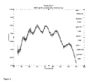
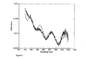
- FIG. 7 shows the calculated tear film reflectance spectrum fit (smooth line) compared to the interferometer measured reflectance spectrum (line with noise) with the (exp ( ⁇ cc*1000/ ⁇ )) term in the equation for total reflectance.
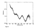
- FIG. 8 shows the calculated tear film reflectance spectrum fit (smooth line) compared to the interferometer measured reflectance spectrum (line with noise) with the (exp ( ⁇ a(1000/ ⁇ )+b(1000/ ⁇ ) 2 ) term in the equation for total reflectance.
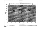
- FIG. 9 shows temporal changes in tear film and corneal surface parameters in Subject 2.
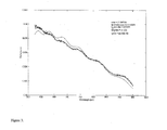
- FIG. 11 shows the calculated tear film reflectance spectrum fit (smooth line) compared to the interferometer measured reflectance spectrum (line with noise).
- This invention solves the problem of accurately and precisely measuring tear film lipid layer thickness by applying a new mathematical method to simultaneous tear film lipid and aqueous layer thicknesses and corneal refractive index calculations from interferometry data.
- the mathematical method is based upon electromagnetic and scalar scattering theories and thin film physics and includes two empirically-discovered factors, “bb” and “exp( ⁇ cc*1000/ ⁇ )”, wherein bb and cc are numbers, to account respectively for interferometer light losses/gains and light scattering at an optically rough surface.
- the mathematical method for simultaneous tear film lipid and aqueous layers thicknesses and corneal refractive index calculations from interferometry data comprises the steps of: selecting a patient; aligning an eye of the patient with light originating from a light source; measuring tear film and ocular surface light reflectance of a patient; determining a value for tear film aqueous layer thickness, creating a mathematical construct of tear film and ocular surface light reflectance R based upon a characteristic mathematical matrix of a thin film stack comprising in sequence from top to bottom: air as a boundary, a tear film lipid layer, the tear film aqueous layer and a corneal epithelium as a semi-infinite substrate; multiplying R by two terms, bb and exp( ⁇ cc.*(1000./L). ⁇ 1.0), wherein bb and cc are numbers, to find lipid and aqueous layer thicknesses and corneal surface refractive index and determining whether the tear film and ocular surface is deficient.
- This new mathematical method provides a better determination of tear film lipid layer thickness than previous more empirical methods.
- This new method also provides a more accurate calculation of tear film aqueous layer thickness determination and provides for the first time a value for the corneal epithelial refractive index at the precise boundary of the aqueous layer and the surface of the corneal epithelium, believed to be the corneal glycocalyx.
- This new method requires one to take under consideration all of the optical characteristics of interferometry measurements and the tear film as well as the optical characteristics of the corneal epithelial surface, which forms the underlying substrate for the tear film. Using this method, a practitioner may determine whether the tear film meets acceptable parameters, or whether it is deficient in any way by comparison to a reference value.
- such deficiencies may include aqueous deficiencies, lipid deficiencies or deficiencies of the corneal surface. If the practitioner is a doctor, the deficiency may be treated by way of an appropriate medication. If the practitioner is a researcher, this deficiency may be noted as a way to steer research and/or development of a new medication.
- n n air (n 0 ) lipid: 20-120 nm (n 1 ) aqueous: 1-5 microns (n 2 ) corneal epithelium (n 3 )
- the last denominator here, (b(2)+0.00306.*(1000./L). ⁇ 2), is expressed as v5 in software code, as the program needs to iteratively fit the best value of n 3 to the observed data and thus n 3 also becomes a determined output.
- the film stack is first treated mathematically as in Hecht (Optics, Eugene Hecht, 4 th ed., pp. 426-428, Pearson Education, Inc., Addison Wesley, 1301 Sanome St., San Francisco, Calif. 94111, 2002). Electric and magnetic field intensities are designated conventionally, as E and H, respectively, with subscripts I, II or III referring to these fields at the respective boundaries.
- E and H Electric and magnetic field intensities
- E I E II cos k 0 h+H II ( i sin k 0 h )/ ⁇ 1
- H I E II ⁇ 1 i sin k 0 h+H II cos k 0 h,
- ⁇ 1 ⁇ 0 ⁇ 0 ⁇ n 1 ⁇ cos ⁇ ⁇ ⁇
- [ E I H I ] M ⁇ [ E II H II ]
- ⁇ 0 ⁇ 0 / ⁇ 0 )*n 0 cos ⁇ .
- E refelected ⁇ ⁇ total E total ⁇ E r ⁇ ⁇ 01 + E t ⁇ ⁇ 10
- E i ⁇ ⁇ 01 ⁇ ⁇ 0 ⁇ m 11 + ⁇ 0 ⁇ ⁇ 2 ⁇ m 12 - m 21 - ⁇ 2 ⁇ m 22 ⁇ 0 ⁇ m 11 + ⁇ 0 ⁇ ⁇ 2 ⁇ m 12 + m 21 + ⁇ 2 ⁇ m 22
- E i ⁇ ⁇ 01 ⁇ 2 ⁇ ⁇ 0 ⁇ 0 ⁇ m 11 + ⁇ 0 ⁇ ⁇ 2 ⁇ m 12 + m 21 + ⁇ 2 ⁇ m 22
- the characteristic matrix, M, above, also written as M I relates the fields at the two adjacent boundaries in the above system with a single film between two semi-infinite transparent media. If there are two overlying films on a substrate, e.g., the tear film lipid and aqueous layers on the corneal epithelial substrate, the resultant system matrix is calculated by multiplication of the individual matrices of the lipid and aqueous layers.
- [ E I H I ] [ M I ⁇ M II * E III H III ]
- h 1 (lipid layer 1) 2 n 1 d lip cos ⁇
- h 2 (aqueous layer 2) 2 n 2 d aq cos ⁇
- d lip is the thickness of the tear film lipid layer (expressed as “a” in software code)
- d aq is the thickness of the tear film aqueous layer (expressed as “d” in software code)
- 2
- , where ⁇ 2 is replaced by ⁇ 3 , since our substrate is the corneal epithelium, and where ⁇ 3 has its corresponding value based upon n 3 and cos ⁇ , e.g., ⁇ 3 ⁇ ( ⁇ 0 / ⁇ 0 )*n 3 cos ⁇ .
- Reflectance is a measure of the proportion of intensities rather than field amplitudes. Reflectance is calculated since measurements can only be made of intensities.
- Matrix terms m 11 , m 12 , m 21 and m 22 are calculated from standard matrix algebra as follows:
- ⁇ 0 m 11 ⁇ ( ⁇ 0 / ⁇ 0 )*n 0 cos ⁇ .*cos((2.* ⁇ )./ ⁇ ).
- R2 ((((abs(((1.*cos(0.091)).*(cos((((2.*pi)./L).* sqrt(1+((( ⁇ 851.03).*L.*L)./(L.*L ⁇ (816.139)))+(((420.267).*L.*L)./(L.*L ⁇ ( ⁇ 706.86)))+ (((431.856).*L.*L)./(L.*L ⁇ (2355.29)))).*a.*cos(asin(1.*sin(0.091)./sqrt(1+ ((( ⁇ 851.03).*L.*L)./(L.*L ⁇ (816.139)))+(((420.267).*L.*L)./(L.*L ⁇ (706.86))+ (((431.856).*L.*L)./(L.*L ⁇ (2355.29)))))).*cos(((2.*pi).
- the final equation and software require that an initial value for tear film aqueous layer thickness be used.
- This initial value for tear film aqueous layer thickness can be derived from methods disclosed in U.S. Pat. No. 7,963,655 B2, which is incorporated herein by reference.
- the aqueous layer thickness of the tear film averages about 3000 nm for non-contact lens wearers, this can be used as an input starting value for non-contact lens wearers.
- the aqueous layer thickness of the tear film averages about 2500 nm for contact lens wearers, this can be used as an input starting value for contact lens wearers.
- the final equation also includes two additional terms, bb and exp( ⁇ cc.*(1000./L). ⁇ 1.0), wherein bb and cc are numbers, not described by the theory for the characteristic matrix for a film stack.
- the first term, bb was determined to be required to increase or decrease the mathematically-fitted reflectance, R, at each measured wavelength, to achieve a better fit to measured reflectance. This is necessary since the interferometer measures only relative reflectance of the tear film, relative to the measured reflectance of a glass lens standard, not absolute reflectance. Thus, interferometer instrument raw data are quotients of measured reflectance of the tear film divided by the measured reflectance of the glass lens standard. Measured tear film reflectance is subject to changes in light intensity, depending upon focus and eye alignment, since the instrument is designed to reflect only a small spot of light from the apex of the cornea.
- This term evolved from an initial failed attempt to use scalar light scattering theory and a theoretical Gaussian distribution of substrate (e.g., the corneal epithelium in our case) surface height variation, which involved multiplying R by exp( ⁇ cc.*(1000./L). ⁇ 2.0).
- Scalar scattering theory is based upon the principle that longer light wavelengths are scattered by a rough surface less than shorter wavelengths, resulting in interference peak and trough amplitude modulation. In other words, interference spectra of thin films overlying rough surfaces are expected to have larger oscillations at longer wavelengths, due to variation of thickness of the thin film layer caused by variation of surface roughness (height) of the underlying surface.
- the format of this second term accounts for both non-Gaussian and Gaussian distributions in surface roughness. It is anticipated that other non-Gaussian surface roughness distributions will have to be accounted-for when using the methods of the present invention.
- Such surface roughness distributions can be mathematically modeled using mathematics terms as in Rakels J. Influence of the surface height distribution on the total integrated scatter (TIS) formula. Nanotechnology 7 (1996): 43-46, which is incorporated herein in its entirety by reference.
- any non-Gaussian height distribution function or single mathematical term may be employed, whose relevance can be determined by the goodness of fit methods of the present invention, comparing a fitted function R comprising a non-Gaussian height distribution function or single mathematical term to experimentally measured interference spectra.
- a least squares minimization technique is preferably employed, where an error function is evaluated and minimized.
- Software was developed using the MatLab® software platform from The MathWorks, Inc.
- the software of the present invention uses the Gauss-Newton method to find the optimal values for the refractive index of the corneal epithelium, thickness of the lipid layer and “bb” and “cc” parameters.
- Other fitting-error minimization methods other than the Gauss-Newton method may also be employed, which are well-known in the art, such as the Levenberg-Marquardt algorithm.
- the mathematical method for simultaneous tear film lipid and aqueous layers thicknesses and corneal refractive index calculations from interferometry data comprises the steps of: selecting a patient; aligning an eye of the patient with light from a light source; measuring tear film and ocular surface light reflectance of a patient; determining a value for tear film aqueous layer thickness, fitting the light reflectance from the eye of the patient to a mathematical construct of tear film and ocular surface light reflectance R based upon a characteristic mathematical matrix of a thin film stack comprising in sequence from top to bottom: air as a boundary, a tear film lipid layer, the tear film aqueous layer and a corneal epithelium as a semi-infinite substrate; multiplying R by two terms, bb and exp( ⁇ cc.*(1000/L). ⁇ 1.0), wherein bb and cc are numbers, to find lipid and aqueous layer thicknesses and conical surface refractive index and determining whether the tear film and ocular surface is
- aqueous layer thickness of the tear film in non-contact lens wearers can be used as an input starting value and the step for determining a value for aqueous layer thickness in the method above can be omitted.
- aqueous layer thickness of the tear film in contact lens wearers can be used as an input starting value and the step for determining a value for aqueous layer thickness in the method above can be omitted.
- the bb term becomes 1, and thus can be omitted.
- This new method provides a value for the conical epithelial refractive index at the precise boundary of the aqueous layer and the surface of the corneal epithelium, believed to be the corneal glycocalyx.
- the glycocalyx is comprised of the membrane-spanning mucin MUC16. When MUC16 is lost or shed, a dry spot can form. Since the integrity of the corneal glycocalyx is known to be required for tear film stability and prevention of dry eye, this new method offers a potential new diagnostic tool for the diagnosis of dry eye.
- This new method can be used for both non-contact lens wearers and contact lens wearers.
- the method can be used to evaluate the efficacy and retention time of novel lubricant eye drops such as those based upon oil-in-water emulsions and which are designed to supplement the lipid or lipid and aqueous layers of the tear film.
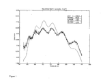
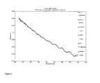
- FIGS. 1 and 2 show the calculated tear film reflectance spectrum fits in smooth lines compared to the interferometer measured reflectance spectra in the lines with noise (small changes in measured reflectance observed as vertical lines).
- FIG. 1 shows that application of the method of the invention without the (exp ( ⁇ cc*1000/ ⁇ )) term in the equation for total reflectance, R, results in a poor fit of the calculated tear film reflectance spectrum (smooth line) to that of the measured reflectance spectrum (line with noise).
- the lipid layer thickness is calculated to be 130 nm in this case.
- FIG. 2 shows that application of the method of the invention with the (exp ( ⁇ cc*1000/ ⁇ )) term in the equation for total reflectance, R, results in an excellent fit of the calculated tear film reflectance spectrum (smooth line) to that of the measured reflectance spectrum (line with noise).
- the lipid layer thickness is calculated to be 100 nm in this case.
- Aqueous layer thickness is the same in both cases, 3.309 microns.
- lipid and aqueous layer thickness values are considered to be within the range of values considered non-deficient.
- Calculations for the refractive index of the corneal epithelium are essentially the same in both cases, 1.3361 and 1.3358 respectively, for FIGS. 1 and 2 .
- the (exp ( ⁇ cc*1000/ ⁇ )) term accounts for a hypothetical non-Gaussian distribution in corneal surface roughness. This is believed due to the macroscopic size of the imaged area of the tear film (12.5 ⁇ 133 microns) and the variation of thickness of the aqueous layer caused by the variation of surface roughness (height) of the corneal surface.
- FIGS. 3 and 4 show the calculated tear film reflectance spectrum fits in smooth lines compared to the interferometer measured reflectance spectra in the lines with noise.
- FIG. 3 shows that application of the method of the invention without the (exp ( ⁇ cc*1000/ ⁇ )) term in the equation for total reflectance, R, results in a poor fit of the calculated tear film reflectance spectrum (smooth line) to that of the measured reflectance spectrum (line with noise).
- the lipid layer thickness is calculated to be 111 nm in this case.
- FIG. 4 shows that application of the method of the invention with the (exp ( ⁇ cc*1000/ ⁇ )) term in the equation for total reflectance, R, results in an excellent fit of the calculated tear film reflectance spectrum (smooth line) to that of the measured reflectance spectrum (line with noise).
- the lipid layer thickness is calculated to be 81 nm in this case.
- Aqueous layer thicknesses are similar in both cases, 2.96 and 3.002 microns respectively, for FIGS. 3 and 4 . These lipid and aqueous layer thickness values are considered to be within the range of values considered non-deficient. Calculations for the refractive index of the corneal epithelium are close in both cases, 1.336 and 1.3350 respectively, for FIGS. 3 and 4 .
- FIGS. 5 and 6 show the calculated tear film reflectance spectrum fits (smooth lines) compared to the interferometer measured reflectance spectra (lines with noise).
- FIG. 5 shows that application of the method of the invention without the (exp ( ⁇ cc*1000/ ⁇ )) term in the equation for total reflectance, R, results in a poor fit of the calculated tear film reflectance spectrum (smooth line) to that of the measured reflectance spectrum (line with noise).
- the lipid layer thickness is calculated to be 34 nm in this case.
- FIG. 6 shows that application of the method of the invention with the (exp ( ⁇ cc*1000/ ⁇ )) term in the equation for total reflectance, R, results in a good fit of the calculated tear film reflectance spectrum (smooth line) to that of the measured reflectance spectrum (line with noise).
- the lipid layer thickness is calculated to be 79 nm in this case.
- This lipid layer thickness value is considered to be within the range of values considered non-deficient.
- Aqueous layer thicknesses are similar in both cases, 6.040 and 6.120 microns respectively, for FIGS. 5 and 6 .
- An aqueous layer thickness value well above a value of 3 microns is indicative of either benign reflex tearing or tearing due to the presence of a foreign body or inflammatory process. A determination between these alternatives was not made.
- Calculations for the refractive index of the corneal epithelium are different, 1.3346 and 1.3324 respectively, for FIGS. 5 and 6 .
- FIGS. 7 and 8 show the calculated tear film reflectance spectrum fits (smooth lines) compared to the interferometer measured reflectance spectra (lines with noise).
- FIG. 7 shows that application of the method of the invention with the (exp ( ⁇ cc*1000/ ⁇ ) term in the equation for total reflectance, R, results in a poor fit of the calculated tear film reflectance spectrum (smooth line) to that of the measured reflectance spectrum (line with noise).
- the lipid layer thickness is calculated to be 37.8 nm in this case.
- FIG. 8 shows that application of the method of the invention with the (exp ( ⁇ a(1000/ ⁇ )+b(1000/ ⁇ ) 2 ) term in the equation for total reflectance, R, results in a good fit of the calculated tear film reflectance spectrum (smooth line) to that of the measured reflectance spectrum (line with noise).
- the lipid layer thickness is calculated to be 86.1 nm in this case.
- Aqueous layer thicknesses are similar in both cases, 3.040 and 2.985 microns respectively, for FIGS. 7 and 8 . Again, these lipid and aqueous layer thickness values are considered to be within the range of values considered non-deficient.
- Calculations for the refractive index of the corneal epithelium are similar, 1.3344 and 1.3349 respectively, for FIGS. 7 and 8 .
- the additional exponential term, b(1000/ ⁇ ) 2 is believed to account for a Gaussian corneal surface roughness factor, occurring simultaneously with a non-Gaussian surface roughness, accounted for by the ( ⁇ a(1000/ ⁇ ) term, within the relative large imaged surface area (12.5 ⁇ 133 microns).
- Interferometric reflectance spectra of human subject's right eye baseline tear films are taken, as described in U.S. Pat. No. 7,963,655 B2.
- Measured reflectance data are processed according to the method of the present invention with the application of the correction with either the (exp ( ⁇ cc*1000/ ⁇ )) or (exp ( ⁇ a(1000/ ⁇ )+b(1000/ ⁇ ) 2 ; subject 2, scans CJ through CN) term and consistently with the bb termin the equation for total reflectance, R.
- Table 1 presents results of simultaneous measurements and calculations of tear film lipid and aqueous layer thicknesses and corneal surface refractive index.
- Tear film lipid and aqueous layer thickness values are consistent with literature (King-Smith P E, Fink B A, Fogt N, Nichols K K, Hill R M, Wilson G S. The Thickness of the Human Precorneal Tear Film Evidence from reflection Spectra. Invest Ophthalmol Vis Sci. 2000; 41:3348-3359; Korb D R, Baron D F, Herman J P, Finnemore V M, Exford J M, Hermosa J L, Leahy C D, Glonek T, Greiner W. Tear film lipid layer thickness as a function of blinking. Cornea. 1994; 13(4): 354-359).
- a tear lipid layer thickness of 34 nm potentially represents a tear lipid deficiency.
- An aqueous layer thickness of 1546 nm potentially represents a tear aqueous deficiency.
- Table 2 and FIG. 9 show the time sequence of tear film lipid, aqueous and conical surface refractive index measurements, taken from a subset of subject 2 data in Table 1.
- the type of exponential term (exp term) used to correct for surface roughness for each spectrum in Table 2 is referenced by way of referring to the preceding example in which it was used, e.g. Ex. 1 or Ex. 2.
- Sequential interferometric measurements were taken for subject 2 every 0.168 msec for a 25.2 second period.
- Data in Table 2 present scan data from 14.448-17.472 seconds. Tear film aqueous layer thickness in nanometers (nm) was divided by 20 for plotting purpose.
- Corneal surface refractive index was multiplied by 10000 and then 13300 was subtracted from this for plotting purposes. This time interval was selected because it encompasses a single eyelid blink at 14.784 seconds, visualized by a sudden increase in tear film aqueous layer thickness from 2368 nm to 3143 nm. It is also seen that the tear film lipid layer thickness rose from a minimum thickness of 75.6 nm at 14.616 seconds just before the blink, to a maximum of 107.6 nm at 15.792 seconds after the blink. Thus, the tear film lipid layer increased in thickness by 32.0 nm in 1.176 seconds.
- Table 3 presents average corneal surface refractive index calculations taken from data in Table 1, along with refractive index data from subjects wherein a single measurement was taken.
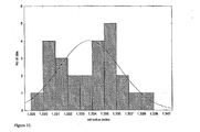
- Refractive index distribution was bimodal, with peaks at 1.3300-1.3310 and 1.3350-1.3360, wherein 15 out of 25 subjects had mean values lower than a low reported value of 1.3346 for the tear film.
- Corneal surface refractive index values comparable to those of the tear film confirm a prior hypothesis (King-Smith P E, Fink B A, Fogt N, Nichols K K, Hill R M, Wilson G S. The Thickness of the Human Precorneal Tear Film: Evidence from reflection Spectra. Invest Ophthalmol Vis Sci. 2000; 41:3348-3359). Corneal surface refractive index values lower than those of the aqueous tear were unexpected.
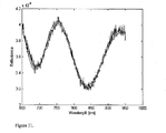
- FIG. 11 shows the calculated tear film reflectance spectrum (smooth line) compared to the interferometer measured reflectance spectrum (line with noise). An excellent fit is obtained.
- a tear film lipid layer thickness of 38.6 nm was calculated, along with a tear film aqueous layer thickness of 1365.4 nm and a contact lens surface refractive index of 1.3553.
- tear film lipid and aqueous layer thickness values are substantially lower than those of an individual without tear lipid or aqueous layer deficiencies who is not wearing a contact lens and are generally consistent with the known thinner tear film lipid and aqueous layers among contact lens wearers. While the 1.3553 refractive index is considerably lower than that of a reported value of 1.4053 for the ACUVUE® 2 lens, the refractive index of this lens has also been reported to be a low as 1.361 (M. Lira et al. Contact Lens & Anterior Eye 31 (2008) 89-94).
- ACUVUE® 2 soft hydrophilic hydrogel contact lens surfaces have considerable water-binding capacity, which could lower the surface refractive index from that of the bulk polymer.
- these and other contact lenses adsorb proteins such as tear mucins, with considerable water-binding capacity, which may also result in a lower contact lens surface refractive index. It is anticipated that in-vivo contact lens surface refractive index measurements will be related to surface hydrophilicity and macroscopic contact lens surface wetting in-eye, an important parameter relating to contact lens comfort.
Abstract
Description
- The invention relates to measurement and analysis of the ocular environment.
- Dry eye disease affects approximately 12 million people in the US. The integrity of the tear film lipid and aqueous layers is critical for proper tear film function and avoidance of dry eye. Wavelength-dependent optical interferometry has been used to simultaneously measure tear film lipid and aqueous layers thicknesses at a single point at the apex of the cornea over a period of time. Such measurements can be used to diagnose sub categories of dry eye from (a) either lipid or aqueous deficiencies, or (b) time-profile changes in lipid and aqueous layer thicknesses after a blink.
- Accurate and precise determination of lipid and aqueous layer thicknesses are critical for proper diagnosis of dry eye sub categories. Previous lipid and aqueous layer thickness calculation methods using interferometry data were conducted separately. This was due to the large differences in layer thicknesses (aqueous: 1-5 microns, lipid: 20-120 nanometers), basing aqueous thickness calculations upon spectral interference oscillations and absence of spectral oscillations from the lipid layer.
- The latter absence of spectral oscillations from the lipid layer presents a difficulty in calculating tear film lipid layer thickness. Thus, there is a need for improvement in the accurate and precise determination of the thickness of the lipid layer. This improvement would be beneficial to the physician, and would allow researchers to better design lubricant eye drops for dry eye patients with meibomian gland dysfunction (MGD). Improved measurement methods may also allow researchers to design more comfortable contact lens and lens care solutions for contact lens wearers. Contact lens wear adversely affects the tear film lipid layer, which is thought to be responsible for the thinner, less stable tear film and resulting dryness among contact lens wearers than non-lens wearers.
- Lastly, there are no known non-invasive diagnostic methods in the art for measuring the refractive index of the corneal epithelium at the precise boundary of the aqueous layer and the anterior surface of the corneal epithelium, known as the corneal glycocalyx. Anterior corneal surface refractive index is believed to be a parametric measurement directly related to the structure of the glycocalyx. The glycocalyx is comprised of transmembrane mucins and the integrity of the corneal glycocalyx is believed to be required for tear film stability and prevention of dry eye. Having such a diagnostic tool would assist researchers in the diagnosis of dry eye and development of compositions which could assist or restore a patient's glycocalyx function. Simultaneous in vivo measurements of this interface, along with tear film aqueous and lipid layer measurements, all of which comprise the ocular environment, may prove to be of use in dry eye diagnosis or elucidating dry eye etiology or ocular effects of topically-applied solutions.
-
FIG. 1 shows a tear film spectrum fit (smooth line) before non-Gaussian corneal surface height correction. The 6 observed peaks are aqueous film spectral interference oscillations (3.309 microns). The large spectrum curvature is due to the lipid layer (130 nm). -
FIG. 2 shows a tear film spectrum fit (smooth line) after non-Gaussian corneal surface height correction with the (exp (−cc*1000/λ)) term, wherein cc is a number representing a fitted parameter proportional to average surface roughness (height). Lipid=100 nm, aqueous=3.309 microns. -
FIG. 3 shows the calculated tear film reflectance spectrum fit in smooth line compared to the interferometer measured reflectance spectrum in the lines with noise without the (exp (−cc*1000/λ)) term in the equation for total reflectance. -
FIG. 4 shows the calculated tear film reflectance spectrum fit in smooth line compared to the interferometer measured reflectance spectrum in the lines with noise with the (exp (−cc*1000/λ)) term in the equation for total reflectance. -
FIG. 5 shows the calculated tear film reflectance spectrum fit (smooth line) compared to the interferometer measured reflectance spectrum (line with noise) without the (exp (−cc*1000/λ) term in the equation for total reflectance. -
FIG. 6 shows the calculated tear film reflectance spectrum fit (smooth line) compared to the interferometer measured reflectance spectrum (line with noise) with the (exp (−cc*1000/λ)) term in the equation for total reflectance. -
FIG. 7 shows the calculated tear film reflectance spectrum fit (smooth line) compared to the interferometer measured reflectance spectrum (line with noise) with the (exp (−cc*1000/λ)) term in the equation for total reflectance. -
FIG. 8 shows the calculated tear film reflectance spectrum fit (smooth line) compared to the interferometer measured reflectance spectrum (line with noise) with the (exp (−a(1000/λ)+b(1000/λ)2) term in the equation for total reflectance. -
FIG. 9 shows temporal changes in tear film and corneal surface parameters inSubject 2. -
FIG. 10 shows a histogram of corneal surface refractive index (n=25). Deviation from normal distribution (smooth curve) shown. Values range from above pure water at 35° C. (1.32737) through and above the range of values reported for human tear film (nd=1.3346−1.3371). -
FIG. 11 shows the calculated tear film reflectance spectrum fit (smooth line) compared to the interferometer measured reflectance spectrum (line with noise). - This invention solves the problem of accurately and precisely measuring tear film lipid layer thickness by applying a new mathematical method to simultaneous tear film lipid and aqueous layer thicknesses and corneal refractive index calculations from interferometry data. The mathematical method is based upon electromagnetic and scalar scattering theories and thin film physics and includes two empirically-discovered factors, “bb” and “exp(−cc*1000/λ)”, wherein bb and cc are numbers, to account respectively for interferometer light losses/gains and light scattering at an optically rough surface.
- The mathematical method for simultaneous tear film lipid and aqueous layers thicknesses and corneal refractive index calculations from interferometry data comprises the steps of: selecting a patient; aligning an eye of the patient with light originating from a light source; measuring tear film and ocular surface light reflectance of a patient; determining a value for tear film aqueous layer thickness, creating a mathematical construct of tear film and ocular surface light reflectance R based upon a characteristic mathematical matrix of a thin film stack comprising in sequence from top to bottom: air as a boundary, a tear film lipid layer, the tear film aqueous layer and a corneal epithelium as a semi-infinite substrate; multiplying R by two terms, bb and exp(−cc.*(1000./L).̂1.0), wherein bb and cc are numbers, to find lipid and aqueous layer thicknesses and corneal surface refractive index and determining whether the tear film and ocular surface is deficient.
- This new mathematical method provides a better determination of tear film lipid layer thickness than previous more empirical methods. This new method also provides a more accurate calculation of tear film aqueous layer thickness determination and provides for the first time a value for the corneal epithelial refractive index at the precise boundary of the aqueous layer and the surface of the corneal epithelium, believed to be the corneal glycocalyx. This new method requires one to take under consideration all of the optical characteristics of interferometry measurements and the tear film as well as the optical characteristics of the corneal epithelial surface, which forms the underlying substrate for the tear film. Using this method, a practitioner may determine whether the tear film meets acceptable parameters, or whether it is deficient in any way by comparison to a reference value. By way of example, but not of limitation, such deficiencies may include aqueous deficiencies, lipid deficiencies or deficiencies of the corneal surface. If the practitioner is a doctor, the deficiency may be treated by way of an appropriate medication. If the practitioner is a researcher, this deficiency may be noted as a way to steer research and/or development of a new medication.
- A wavelength-dependent optical interferometer of the type developed by King-Smith et al and Huth (King-Smith P E, Fink B A, Fogt N, Nichols K K, Hill R M, Wilson G S. The thickness of the human precorneal tear film: evidence from reflection spectra. Invest Ophthalmol Vis Sci 2000; 41:3348-3359; Huth, U.S. Pat. No. 7,963,655 B2) was utilized. The tear film was modeled as a stack of 2 homogeneous films between air as a semi-infinite medium and the cornea as a semi-infinite substrate:
-
air (n0) lipid: 20-120 nm (n1) aqueous: 1-5 microns (n2) corneal epithelium (n3)
The refractive indices, nn, were derived from literature, where
n0=1,
n1=sqrt(1+(((−851.03).*L.*L)./(L.*L−(816.139)))+(((420.267).*L.*L)./(L.*L−(−706.86)))+(((431.856).*L.*L)./(L.*L−(2355.29)))), derived from a Sellmeier equation fit of data from Tiffany (Tiffany, J M. Refractive index of meibomian and other lipids. Current Eye Research, 5 (11), 1986, 887-889),
n2=1.32806+0.00306.*(1000./L).̂2 from Ewen King-Smith, personal communication. and
n3=b(2)+0.00306.*(1000./L).̂2, where b(2) starting value=1.338 since the cornea refractive index at the aqueous tear interface is unknown (n3 is expressed as v5 in software code, since it is a fitted term), and where
L=λ, nm for n1, n2 and n3
There are a total of 3 boundaries at the interfaces between media of differing refractive indices:
Boundary I: between air and the lipid layer of the tear film
Boundary II: between the lipid and aqueous layers of the tear film
Boundary III: between the aqueous layer of the tear film and the corneal epithelium
The angle of incidence θ onto the apex of the cornea of the incident light source in the interferometer was 0.091 radians. Other angles of refraction into a layer and incidence onto the succeeding layer are defined and expressed mathematically as follows from Snell's law:
n0 sin θ=n1 sin β;
n1 sin β=n2 sin γ and
n2 sin γ=n3 sin δ
and from the equations above for n0, n1, n2 and n3, and where:
angle of incident light onto the lipid layer, angle θ=0.091 radians;
angle of incident light onto the aqueous layer=angle β;
angle of incident light onto the corneal surface=angle γ and
angle of refracted light into the cornea=angle δ.
Refracted light in the lipid layer=incidence angle onto the aqueous layer=angle β, where β=asin(no sin θ/n1)=asin(1.*sin(0.091)./sqrt(1+(((−851.03).*L.*L)./(L.*L−(816.139)))+(((420.267).*L.*L)./(L.*L−(−706.86)))+(((431.856).*L.*L)./(L.*L−(2355.29)))));
Refracted light in the aqueous layer=incidence angle onto the corneal epithelium=angle γ, where γ=asin(n1 sin β/n2)=asin(n1 sin(asin(no sin θ/n1)/n2))=asin (sqrt(1+(((−851.03).*L.*L)./(L.*L−(816.139)))+(((420.267).*L.*L)./(L.*L−(−706.86)))+(((431.856).*L.*L)./(L.*L−(2355.29)))).*sin(asin(1.*sin(0.091)./sqrt(1+(((−851.03).*L.*L)./(L.*L−(816.139)))+(((420.267).*L.*L)./(L.*L−(−706.86)))+(((431.856).*L.*L)./(L.*L−(2355.29))))))./(1.32806+0.00306.*(1000./L).̂2)))); and
Refracted light in the corneal epithelium=angle δ, where δ=asin(n2 sin γ/n3)=asin ((1.32806+0.00306.*(1000./L).̂2).*sin(asin(sqrt(1+(((−851.03).*L.*L)./(L.*L−(816.139)))+(((420.267).*L.*L)./(L.*L−(−706.86)))+(((431.856).*L.*L)./(L.*L−(2355.29)))).*sin(asin(1.*sin(0.091)./sqrt(1+(((−851.03).*L.*L)./(L.*L−(816.139)))+(((420.267).*L.*L)./(L.*L−(−706.86)))+(((431.856).*L.*L)./(L.*L−(2355.29))))))./(1.32806+0.00306.*(1000./L).̂2)))./(b(2)+0.00306.*(1000./L).̂2)))). The last denominator here, (b(2)+0.00306.*(1000./L).̂2), is expressed as v5 in software code, as the program needs to iteratively fit the best value of n3 to the observed data and thus n3 also becomes a determined output.
The film stack is first treated mathematically as in Hecht (Optics, Eugene Hecht, 4th ed., pp. 426-428, Pearson Education, Inc., Addison Wesley, 1301 Sanome St., San Francisco, Calif. 94111, 2002). Electric and magnetic field intensities are designated conventionally, as E and H, respectively, with subscripts I, II or III referring to these fields at the respective boundaries. Thus, for a single thin dielectric film (layer) between two semi-infinite transparent media, -
E I =E II cos k 0 h+H II(i sin k 0 h)/Ω1 -
and -
H I =E IIΩ1 i sin k 0 h+H II cos k 0 h, -
where -
- and where h=2 n1d cos β, where d=layer thickness.
In matrix notation, these linear equations take the form, -
- Expansion of this equation using the values for EI, HI, EII and HII derived from the boundary condition requirements that the tangential components of both the electric and magnetic fields be equal across the boundaries yields the following expanded expression:
-
- and Ω0 has its corresponding value based upon n0 and cos θ, e.g., Ω0=√∈0/μ0)*n0 cos θ.
When the components of this matrix are expanded, one obtains the reflection (r) and transmission (t) coefficients: -
- The characteristic matrix, M, above, also written as MI, relates the fields at the two adjacent boundaries in the above system with a single film between two semi-infinite transparent media. If there are two overlying films on a substrate, e.g., the tear film lipid and aqueous layers on the corneal epithelial substrate, the resultant system matrix is calculated by multiplication of the individual matrices of the lipid and aqueous layers.
-
- where h1 (lipid layer 1)=2 n1dlip cos β, h2 (aqueous layer 2)=2 n2daq cos γ, where dlip is the thickness of the tear film lipid layer (expressed as “a” in software code), daq is the thickness of the tear film aqueous layer (expressed as “d” in software code), where Ω1 and Ω2 have their previous definitions and where k0=π/λ. From this, reflectance is calculated from:
R=|r|2=|(Ω0m11+Ω0Ω3m12−m21−Ω3m22)/(Ω0m11+Ω0Ω3m12+m21+Ω3m22)|, where Ω2 is replaced by Ω3, since our substrate is the corneal epithelium, and where Ω3 has its corresponding value based upon n3 and cos δ, e.g., Ω3=√(∈0/μ0)*n3 cos δ. Reflectance is a measure of the proportion of intensities rather than field amplitudes. Reflectance is calculated since measurements can only be made of intensities. Matrix terms m11, m12, m21 and m22 are calculated from standard matrix algebra as follows: -
- Thus, ae+bg=m11; af+bh=m12; ce+dg=m21; and cf+dh=m22.
An example of matrix term calculation and expansion follows. From matrix algebra, m11=cos k0h1*cos k0h2+i sin k0h1/Ω1*Ω2i sin k0h2=cos((2.*π)./λ).*n1dlip cos β)*cos ((2.*π)./λ).*n2daq cos γ+((i sin((2.*π)./λ).*n1dlip cos β)/(√(∈0/μ0)*n1 cos β))*(√(∈0μ0)*n2 cos γ*i sin((2.*π)./λ).*n2daq cos γ).
Thus, Ω0m11=√(∈0/μ0)*n0 cos θ.*cos((2.*π)./λ).*n1dlip cos β)*cos((2.*π)./λ).*n2daq cos γ+√(∈0/μ0)*n0 cos θ.*((i sin((2.*π)./λ).*n1dlip cos β)/(√(∈0/μ0)*n1 cos β))*(√(∈0/μ0)*n2 cos γ*i sin((2.*π)./λ).*n2daq cos γ).
In the software code for calculating R=|r|2, the equation for the first term, Ω0m11, is expanded using values and equations above for n0, n1, n2, θ, β and γ to: -
Ω0m11=((((((1.*cos(0.091)).*(cos((((2.*pi)./L).*sqrt(1+ (((−851.03).*L.*L)./(L.*L− (816.139)))+(((420.267).*L.*L)./(L.*L−(−706.86)))+ (((431.856).*L.*L)./(L.*L− (2355.29)))).*a.*cos(asin(1.*sin(0.091)./sqrt(1+ (((−851.03).*L.*L)./(L.*L− (816.139)))+(((420.267).*L.*L)./(L.*L−(−706.86)))+ (((431.856).*L.*L)./(L.*L− (2355.29)))))))).*cos((((2.*pi)./L).*(1.32806+0.00306.* (1000./L).{circumflex over ( )}2).*d.*cos(asin(sqrt(1+ (((−851.03).*L.*L)./(L.*L−(816.139)))+ (((420.267).*L.*L)./(L.*L−(− 706.86)))+(((431.856).*L.*L)./(L.*L−(2355.29)))).*sin (asin(1.*sin(0.091)./sqrt(1+(((− 851.03).*L.*L)./(L.*L−(816.139)))+ (((420.267).*L.*L)./(L.*L−(− 706.86)))+(((431.856).*L.*L)./(L.*L− (2355.29))))))./(1.32806+0.00306.*(1000./L).{circumflex over ( )}2)))))− (((1.32806+0.00306.*(1000./L).{circumflex over ( )}2).*cos(asin(sqrt(1+ (((−851.03).*L.*L)./(L.*L− (816.139)))+(((420.267).*L.*L)./(L.*L−(−706.86)))+ (((431.856).*L.*L)./(L.*L− (2355.29)))).*sin(asin(1.*sin(0.091)./sqrt(1+ (((−851.03).*L.*L)./(L.*L− (816.139)))+(((420.267).*L.*L)./(L.*L−(−706.86)))+ (((431.856).*L.*L)./(L.*L− (2355.29))))))./(1.32806+0.00306.*(1000./L).{circumflex over ( )}2))))./ (sqrt(1+(((−851.03).*L.*L)./(L.*L− (816.139)))+(((420.267).*L.*L)./(L.*L−(−706.86)))+ (((431.856).*L.*L)./(L.*L− (2355.29)))).*cos(asin(1.*sin(0.091)./sqrt(1+ (((−851.03).*L.*L)./(L.*L− (816.139)))+(((420.267).*L.*L)./(L.*L−(−706.86)))+ (((431.856).*L.*L)./(L.*L− (2355.29)))))))).*sin((((2.*pi)./L).*(1.32806+0.00306.* (1000./L).{circumflex over ( )}2).*d.*cos(asin(sqrt(1+ (((−851.03).*L.*L)./(L.*L−(816.139)))+ (((420.267).*L.*L)./(L.*L−(− 706.86)))+(((431.856).*L.*L)./(L.*L−(2355.29)))).*sin (asin(1.*sin(0.091)./sqrt(1+(((− 851.03).*L.*L)./(L.*L−(816.139)))+(((420.267).*L.*L)./ (L.*L−(−706.86)))+(((431.856).*L.*L)./(L.*L− (2355.29))))))./(1.32806+0.00306.*(1000./L).{circumflex over ( )}2))))).*sin ((((2.*pi)./L).*sqrt(1+(((− 851.03).*L.*L)./(L.*L−(816.139)))+(((420.267).*L.*L)./ (L.*L−(−706.86)))+(((431.856).*L.*L)./(L.*L− (2355.29)))).*a.*cos(asin(1.*sin(0.091)./sqrt(1+(((− 851.03).*L.*L)./(L.*L−(816.139)))+(((420.267).*L.*L)./ (L.*L−(−706.86)))+(((431.856).*L.*L)./(L.*L− (2355.29)))))))))+(1.*cos(0.091)).*(v5.*cos(asin ((1.32806+0.00306.*(1000./L).{circumflex over ( )}2).*sin(a sin(sqrt(1+(((−851.03).*L.*L)./(L.*L−(816.139)))+ (((420.267).*L.*L)./(L.*L−(− 706.86)))+(((431.856).*L.*L)./(L.*L−(2355.29)))).*sin (asin(1.*sin(0.091)./sqrt(1+(((− 851.03).*L.*L)./(L.*L−(816.139)))+(((420.267).*L.*L)./ (L.*L−(−706.86)))+(((431.856).*L.*L)./(L.*L− (2355.29))))))./(1.32806+0.00306.*(1000./L).{circumflex over ( )}2)))./v5))). - Other terms for calculating R=|r|2 are calculated and expanded similarly, yielding the final equation:
-
R2=((((abs(((1.*cos(0.091)).*(cos((((2.*pi)./L).* sqrt(1+(((−851.03).*L.*L)./(L.*L− (816.139)))+(((420.267).*L.*L)./(L.*L−(−706.86)))+ (((431.856).*L.*L)./(L.*L− (2355.29)))).*a.*cos(asin(1.*sin(0.091)./sqrt(1+ (((−851.03).*L.*L)./(L.*L− (816.139)))+(((420.267).*L.*L)./(L.*L−(706.86)))+ (((431.856).*L.*L)./(L.*L− (2355.29)))))))).*cos((((2.*pi)./L).*(1.32806+ 0.00306.*(1000./L).{circumflex over ( )}2).*d.*cos(asin(sqrt(1+ (((−851.03).*L.*L).1(L.*L−(816.139)))+ (((420.267).*L.*L)./(L.*L−(− 706.86)))+(((431.856).*L.*L)./(L.*L−(2355.29)))).* sin(asin(1.*sin(0.091)./sqrt(1+(((− 851.03).*L.*L)./(L.*L−(816.139)))+ (((420.267).*L.*L)./(L.*L−(− 706.86)))+(((431.856).*L.*L)./(L.*L− (2355.29))))))./(1.32806+0.00306.*(1000./L).{circumflex over ( )}2)))))− (((1.32806+0.00306.*(1000./L).{circumflex over ( )}2).*cos(asin(sqrt(1+ (((−851.03).*L.*L)./(L.*L− (816.139)))+(((420.267).*L.*L)./(L.*L−(−706.86)))+ (((431.856).*L.*L)./(L.*L− (2355.29)))).*sin(asin(1.*sin(0.091)./sqrt(1+ (((−851.03).*L.*L)./(L.*L− (816.139)))+(((420.267).*L.*L)./(L.*L−(−706.86)))+ (((431.856).*L.*L)./(L.*L− (2355.29))))))./(1.32806+0.00306.*(1000./L).{circumflex over ( )}))))./ (sqrt(1+(((−851.03).*L.*L)./(L.*L− (816.139)))+(((420.267).*L.*L)./(L.*L−(−706.86)))+ (((431.856).*L.*L)./(L.*L− (2355.29)))).*cos(asin(1.*sin(0.091)./sqrt(1+ (((−851.03).*L.*L)./(L.*L− (816.139)))+(((420.267).*L.*L)./(L.*L−(−706.86)))+ (((431.856).*L.*L)./(L.*L− (2355.29)))))))).*sin((((2.*pi)./L).*(1.32806+ 0.00306.*(1000./L).{circumflex over ( )}2).*d.*cos(asin(sqrt(1+ (((−851.03).*L.*L)./(L.*L−(816.139)))+ (((420.267).*L.*L)./(L.*L−(− 706.86)))+(((431.856).*L.*L)./(L.*L−(2355.29)))).* sin(asin(1.*sin(0.091)./sqrt(1+(((− 851.03).*L.*L)./(L.*L−(816.139)))+ (((420.267).*L.*L)./(L.*L−(− 706.86)))+(((431.856).*L.*L)./(L.*L− (2355.29))))))./(1.32806+0.00306.*(1000./L).{circumflex over ( )}2))))).* sin((((2.*pi)./L).*sqrt(1+(((− 851.03).*L.*L)./(L.*L−(816.139)))+ (((420.267).*L.*L)./(L.*L−(− 706.86)))+(((431.856).*L.*L)./(L.*L− (2355.29)))).*a.*cos(asin(1.*sin(0.091)./sqrt(1+(((− 851.03).*L.*L)./(L.*L−(816.139)))+ (((420.267).*L.*L)./(L.*L−(− 706.86)))+(((431.856).*L.*L)./(L.*L− (2355.29)))))))))+(1.*cos(0.091)).*(v5.*cos( asin((1.32806+0.00306.*(1000./L).{circumflex over ( )}2).*sin(a sin(sqrt(1+(((−851.03).*L.*L)./(L.*L−(816.139)))+ (((420.267).*L.*L)./(L.*L−(− 706.86)))+(((431.856).*L.*L)./(L.*L−(2355.29)))).* sin(asin(1.*sin(0.091)./sqrt(1+(((− 851.03).*L.*L)./(L.*L−(816.139)))+ (((420.267).*L.*L)./(L.*L−(− 706.86)))+(((431.856).*L.*L)./(L.*L− (2355.29))))))./(1.32806+0.00306.* (1000./L).{circumflex over ( )}2)))./v5))).*(− i.*cos((((2.*pi)./L).*sqrt(1+(((−851.03).*L.*L)./(L.*L− (816.139)))+(((420.267).*L.*L)./(L.*L−(−706.86)))+ (((431.856).*L.*L)./(L.*L− (2355.29)))).*a.*cos(asin(1.*sin(0.091)./sqrt(1+ (((−851.03).*L.*L)./(L.*L− (816.139)))+(((420.267).*L*L)./(L.*L−(−706.86)))+ (((431.856).*L.*L)./(L.*L− (2355.29)))))))).*(sin((((2.*pi)./L).*(1.32806+ 0.00306.*(1000./L).{circumflex over ( )}2).*d.*cos(asin(sqrt(1+ (((−851.03).*L.*L)./(L.*L−(816.139)))+ (((420.267).*L.*L)./(L.*L−(− 706.86)))+(((431.856).*L.*L)./(L.*L−(2355.29)))).* sin(asin(1.*sin(0.091)./sqrt(1+(((− 851.03).*L.*L)./(L.*L−(816.139)))+ (((420.267).*L.*L)./(L.*L−(− 706.86)))+(((431.856).*L.*L)./(L.*L− (2355.29))))))./(1.32806+0.00306.*(1000./L).{circumflex over ( )}2)))))./ ((1.32806+0.00306.*(1000./L){circumflex over ( )}.2). (((−851.03).*L.*L)./(L.*L−(816.139)))+ (((420.267).*L.*L)./(L.*L−(− 706.86)))+(((431.856).*L.*L)./(L.*L−(2355.29)))).* sin(asin(1.*sin(0.091)./sqrt(1+(((− 851.03).*L.*L)./(L.*L−(816.139)))+ (((420.267).*L.*L)./(L.*L−(− 706.86)))+(((431.856).*L.*L)./(L.*L− (2355.29))))))./(1.32806+0.00306.*(1000./L).+2)))))− i.*cos((((2.*pi)./L).*(1.32806+0.00306.* (1000./L).{circumflex over ( )}2).*d.*cos(asin(sqrt(1+(((− 851.03).*L.*L)./(L*L−(816.139)))+ (((420.267).*L.*L)./(L.*L−(− 706.86)))+(((431.856).*L.*L)./(L.*L−(2355.29)))).* sin(asin(1.*sin(0.091)./sqrt(1+(((− 851.03).*L.*L)./(L.*L−(816.139)))+ (((420.267).*L.*L)./(L.*L−(− 706.86)))+(((431.856).*L.*L)./(L.*L− (2355.29))))))./(1.32806+0.00306.*(1000./L).{circumflex over ( )}2))))).* (sin((((2.*pi)./L).*sqrt(1+(((− 851.03).*L.*L)./(L.*L−(816.139)))+ (((420.267).*L.*L)./(L.*L−(− 706.86)))+(((431.856).*L.*L)./(L.*L−(2355.29)))).*a.* cos(asin(1.*sin(0.091)./sqrt(1+(((− 851.03).*L.*L)./(L.*L−(816.139)))+ (((420.267).*L.*L)./(L.*L−(− 706.86)))+(((431.856).*L.*L)./(L.*L−(2355.29))))))))./ (sqrt(1+(((−851.03).*L.*L)./(L.*L− (816.139)))+(((420.267).*L.*L)./(L.*L−(−706.86)))+ (((431.856).*L.*L)./(L.*L− (2355.29)))).*cos(asin(1.*sin(0.091)./sqrt(1+ (((−851.03).*L.*L)./(L.*L− (816.139)))+(((420.267).*L.*L)./(L.*L−(−706.86)))+ (((431.856).*L.*L)./(L.*L− (2355.29)))))))))−(−(sqrt(1+ (((−851.03).*L.*L)./(L.*L− (816.139)))+(((420.267).*L.*L)./(L.*L−(−706.86)))+ (((431.856).*L.*L)./(L.*L− (2355.29)))).*cos(asin(1.*sin(0.091)./sqrt(1+ (((−851.03).*L.*L)./(L.*L− (816.139)))+(((420.267).*L.*L)./(L.*L−(−706.86)))+ (((431.856).*L.*L)./(L.*L− (2355.29))))))).*i.*sin((((2.*pi)./L).*sqrt(1+ (((−851.03).*L.*L)./(L.*L− (816.139)))+(((420.267).*L.*L)./(L.*L−(−706.86)))+ (((431.856).*L.*L)./(L.*L− (2355.29)))).*a.*cos(asin(1.*sin(0.091)./sqrt(1+ (((−851.03).*L.*L)./(L.*L− (816.139)))+(((420.267).*L.*L)./(L.*L−(−706.86)))+ (((431.856).*L.*L)./(L.*L− (2355.29)))))))).*cos((((2.*pi)./L).*(1.32806+ 0.00306.*(1000./L).{circumflex over ( )}2).*d.*cos(asin(sqrt(1+ (((−851.03).*L.*L)./(L.*L−(816.139)))+ (((420.267).*L.*L)./(L.*L−(− 706.86)))+(((431.856).*L.*L)./(L.*L−(2355.29)))).* sin(asin(1.*sin(0.091)./sqrt(1+(((− 851.03).*L.*L)./(L.*L−(816.139)))+ (((420.267).*L.*L)./(L.*L−(− 706.86)))+(((431.856).*L.*L)./(L.*L− (2355.29))))))./(1.32806+0.00306.*(1000./L).{circumflex over ( )}2)))))− cos((((2.*pi)./L).*sqrt(1+(((− 851.03).*L.*L)./(L.*L−(816.139)))+ (((420.267).*L.*L)./(L.*L−(− 706.86)))+(((431.856).*L.*L)./(L.*L−(2355.29)))).* a.*cos(asin(1.*sin(0.091)./sqrt(1+(((− 851.03).*L.*L)./(L.*L−(816.139)))+ (((420.267).*L.*L)./(L.*L−(− 706.86)))+(((431.856).*L.*L)./(L.*L− (2355.29)))))))).*((1.32806+0.00306.* (1000./L).{circumflex over ( )}2).*cos(asin(sqrt(1+(((− 851.03).*L.*L)./(L.*L−(816.139)))+ (((420.267).*L.*L)./(L.*L−(− 706.86)))+(((431.856).*L.*L)./(L.*L−(2355.29)))).* sin(asin(1.*sin(0.091)./sqrt(1+(((− 851.03).*L.*L)./(L.*L−(816.139)))+ (((420.267).*L.*L)./(L.*L−(− 706.86)))+(((431.856).*L.*L)./(L.*L− (2355.29))))))./(1.32806+0.00306.*(1000./L).{circumflex over ( )}2 )))).*i.*sin((((2.*pi)./L).*(1.32806+0.003 06.*(1000./L).{circumflex over ( )}2).*d.*cos(asin(sqrt(1+ (((−851.03).*L.*L)./(L.*L− (816.139)))+(((420.267).*L.*L)./(L.*L− (−706.86)))+(((431.856).*L.*L)./(L.*L− (2355.29)))).*sin(asin(1.*sin(0.091)./sqrt(1+ (((−851.03).*L.*L)./(L.*L− (816.139)))+(((420.267).*L.*L)./(L.*L− (−706.86)))+(((431.856).*L.*L)./(L.*L− (2355.29))))))./(1.32806+0.00306.* (1000./L).{circumflex over ( )}2))))))− (v5.*cos(asin((1.32806+0.00306.* (1000./L).{circumflex over ( )}2).*sin(asin(sqrt(1+(((− 851.03).*L.*L)./(L.*L−(816.139)))+ (((420.267).*L.*L)./(L.*L−(− 706.86)))+(((431.856).*L*L)./(L.*L−(2355.29)))).* sin(asin(1.*sin(0.091)./sqrt(1+(((− 851.03).*L.*L)./(L.*L−(816.139)))+ (((420.267).*L.*L).4.*L−(− 706.86)))+(((431.856).*L.*L)./(L.*L− (2355.29))))))./(1.32806+0.00306.*(1000./L).{circumflex over ( )}2)))./ v5))).*(cos((((2.*pi)./L).*sqrt(1+(((− 851.03).*L.*L)./(L.*L−(816.139)))+ (((420.267).*L.*L)./(L.*L−(− 706.86)))+(((431.856).*L.*L)./(L.*L−( 2355.29)))).*a.*cos(asin(1.*sin(0.091)./sqrt(1+ (((−851.03).*L.*L)./(L.*L−(816.139)))+ (((420.267).*L.*L)./(L.*L−(− 706.86)))+(((431.856).*L.*L)./(L.*L− (2355.29)))))))).*cos((((2.*pi)./L).*(1.32806+ 0.00306.*(1000./L).{circumflex over ( )}2).*d.*cos(asin(sqrt(1+ (((−851.03).*L.*L)./(L.*L−(816.139)))+ (((420.267).*L.*L)./(L.*L−(− 706.86)))+(((431.856).*L.*L)./(L.*L−(2355.29)))).* sin(asin(1.*sin(0.091)./sqrt(1+(((− 851.03).*L.*L)./(L.*L−(816.139)))+ (((420.267).*L.*L)./(L.*L−(− 706.86)))+(((431.856).*L.*L)./(L.*L− (2355.29))))))./(1.32806+0.00306.*(1000./L).{circumflex over ( )}2)))))− ((sqrt(1+(((−851.03).*L.*L)./(L.*L− (816.139)))+(((420.267).*L.*L)./(L.*L−(−706.86)))+ (((431.856).*L.*L)./(L.*L− (2355.29)))).*cos(asin(1.*sin(0.091)./sqrt(1+ (((−851.03).*L.*L)./(L.*L− (816.139)))+(((420.267).*L.*L)./(L.*L−(−706.86)))+ (((431.856).*L.*L)./(L.*L− (2355.29)))))))./((1.32806+0.00306.*(1000./L).{circumflex over ( )}2).* cos(asin(sqrt(1+(((− 851.03).*L.*L)./(L.*L−(816.139)))+ (((420.267).*L.*L)./(L.*L−(− 706.86)))+(((431.856).*L.*L)./(L.*L−(2355.29)))).* sin(asin(1.*sin(0.091)./sqrt(1+(((− 851.03).*L.*L)./(L.*L−(816.139)))+ (((420.267).*L.*L)./(L.*L−(− 706.86)))+(((431.856).*L.*L)./(L.*L− (2355.29))))))./(1.32806+0.00306.*(1000./L).{circumflex over ( )}2))))).* sin((((2.*pi)./L).*sqrt(1+(((− 851.03).*L.*L)./(L.*L−(816.139)))+ (((420.267).*L.*L)./(L.*L−(− 706.86)))+(((431.856).*L.*L)./(L.*L−(2355.29)))).* a.*cos(asin(1.*sin(0.091)./sqrt(1+(((− 851.03).*L.*L)./(L.*L−(816.139)))+ (((420.267).*L.*L)./(L.*L−(− 706.86)))+(((431.856).*L.*L)./(L.*L− (2355.29)))))))).*sin((((2.*pi)./L).*(1.32806+ 0.00306.*(1000./L).{circumflex over ( )}2).*d.*cos(asin(sqrt(1+ (((−851.03).*L.*L)./(L.*L−(816.139)))+ (((420.267).*L.*L)./(L.*L−(− 706.86)))+(((431.856).*L.*L)./(L.*L−(2355.29)))).* sin(asin(1.*sin(0.091)./sqrt(1+(((− 851.03).*L.*L)./(L.*L−(816.139)))+ (((420.267).*L.*L)./(L.*L−(− 706.86)))+(((431.856).*L.*L)./(L.*L− (2355.29))))))./(1.32806+0.00306.* (1000./L).{circumflex over ( )}2)))))))./((1.*cos(0.091)).*(cos((((2.*pi)./ L).*sqrt(1+(((−851.03).*L.*L)./(L.*L−(816.139)))+ (((420.267).*L.*L)./(L.*L−(− 706.86)))+(((431.856).*L.*L)./(L.*L− (2355.29)))).*a.*cos(asin(1.*sin(0.091)./sqrt(1+(((− 851.03).*L.*L)./(L.*L−(816.139)))+ (((420.267).*L.*L)./(L.*L−(− 706.86)))+(((431.856).*L.*L)./(L.*L− (2355.29)))))))).*cos((((2.*pi)./L).*(1.32806+ 0.00306.*(1000./L).{circumflex over ( )}2).*d.*cos(asin(sqrt(1+ (((−851.03).*L.*L)./(L.*L−(816.139)))+ (((420.267).*L.*L)./(L.*L−(− 706.86)))+(((431.856).*L.*L)./(L.*L−(2355.29)))).* sin(asin(1.*sin(0.091)./sqrt(1+(((− 851.03).*L.*L)./(L.*L−(816.139)))+ (((420.267).*L.*L)./(L.*L−(− 706.86)))+(((431.856).*L.*L)./(L.*L− (2355.29))))))./(1.32806+0.00306.*(1000./L).{circumflex over ( )}2)))))− (((1.32806+0.00306.*(1000./L).{circumflex over ( )}2).*cos(asin(sqrt(1+ (((−851.03).*L.*L)./(L.*L− (816.139)))+(((420.267).*L.*L)./(L.*L−(−706.86)))+ (((431.856).*L.*L)./(L.*L− (2355.29)))).*sin(asin(1.*sin(0.091)./sqrt(1+ (((−851.03).*L.*L)./(L.*L− (816.139)))+(((420.267).*L.*L)./(L.*L−(−706.86)))+ (((431.856).*L.*L)./(L.*L− (2355.29))))))/(1.32806+0.00306.*(1000./L).{circumflex over ( )}2))))./ (sqrt(1+(((−851.03).*L.*L)./(L.*L− (816.139)))+(((420.267).*L.*L)./(L.*L−(−706.86)))+ (((431.856).*L.*L)./(L.*L− (2355.29)))).*cos(asin(1.*sin(0.091)./sqrt(1+ (((−851.03).*L.*L)./(L.*L− (816.139)))+(((420.267).*L.*L)./(L.*L−(−706.86)))+ (((431.856).*L.*L)./(L.*L− (2355.29)))))))).*sin((((2.*pi)./L).*(1.32806+ 0.00306.*(1000./L).{circumflex over ( )}2).*d.*cos(asin(sqrt(1+ (((−851.03).*L.*L)./(L.*L−(816.139)))+ (((420.267).*L.*L)./(L.*L−(− 706.86)))+(((431.856).*L.*L)./(L.*L−(2355.29)))).* sin(asin(1.*sin(0.091)./sqrt(1+(((− 851.03).*L.*L)./(L.*L−(816.139)))+ (((420.267).*L.*L)./(L.*L−(− 706.86)))+(((431.856).*L.*L)./(L.*L− (2355.29))))))./(1.32806+0.00306.*(1000./L).{circumflex over ( )}2))))).* sin((((2.*pi)./L).*sqrt(1+(((− 851.03).*L.*L)./(L.*L−(816.139)))+ (((420.267).*L.*L)./(L.*L−(− 706.86)))+(((431.856).*L.*L)./(L.*L−(2355.29)))).* a.*cos(asin(1.*sin(0.091)./sqrt(1+(((− 851.03).*L.*L)./(L.*L−(816.139)))+ (((420.267).*L.*L)./(L.*L−(− 706.86)))+(((431.856).*L.*L)./(L.*L− (2355.29)))))))))+(1.*cos(0.091)).*(v5.*cos(asin ((1.32806+0.00306.*(1000./L).{circumflex over ( )}2).*sin(a sin(sqrt(1+(((−851.03).*L.*L)./(L.*L−(816.139)))+ (((420.267).*L.*L)./(L.*L−(− 706.86)))+(((431.856).*L.*L)./(L.*L−(2355.29)))).* sin(asin(1.*sin(0.091)./sqrt(1+(((− 851.03).*L.*L)./(L.*L−(816.139)))+ (((420.267).*L.*L)./(L.*L−(− 706.86)))+(((431.856).*L.*L)./(L.*L− (2355.29))))))./(1.32806+0.00306.* (1000./L).{circumflex over ( )}2)))./v5))).*(− i.*cos((((2.*pi)./L).*sqrt(1+(((−851.03).*L.*L)./(L.*L− (816.139)))+(((420.267).*L.*L)./(L.*L−(−706.86)))+ (((431.856).*L.*L)./(L.*L− (2355.29)))).*a.*cos(asin(1.*sin(0.091)./sqrt(1+ (((−851.03).*L.*L)./(L.*L− (816.139)))+(((420.267).*L.*L)./(L.*L−(−706.86)))+ (((431.856).*L.*L)./(L.*L− (2355.29)))))))).*(sin((((2.*pi)./L).*(1.32806+ 0.00306.*(1000./L).{circumflex over ( )}2).*d.*cos(asin(sqrt(1+ (((−851.03).*L.*L)./(L.*L−(816.139)))+ (((420.267).*L.*L)./(L.*L−(− 706.86)))+(((431.856).*L.*L)./(L.*L−(2355.29)))).* sin(asin(1.*sin(0.091)./sqrt(1+(((− 851.03).*L.*L)./(L.*L−(816.139)))+ (((420.267).*L.*L)./(L.*L−(− 706.86)))+(((431.856).*L.*L)./(L.*L− (2355.29))))))./(1.32806+0.00306.*(1000./L).{circumflex over ( )}2)))))./ ((1.32806+0.00306.*(1000./L).{circumflex over ( )}2). *cos(asin(sqrt(1+(((−851.03).*L.*L)./(L.*L− (816.139)))+(((420.267).*L.*L)./(L.*L+ 706.86)))+(((431.856).*L.*L)./(L.*L−(2355.29)))).* sin(asin(1.*sin(0.091)./sqrt(1+(((− 851.03).*L.*L)./(L.*L−(816.139)))+ (((420.267).*L.*L)./(L.*L−(− 706.86)))+(((431.856).*L.*L)./(L.*L− (2355.29))))))./(1.32806+0.00306.*(1000./L).{circumflex over ( )}2)))))− i.*cos((((2.*pi)./L).*(1.32806+0.00306.* (1000./L).{circumflex over ( )}2).*d.*cos(asin(sqrt(1+(((− 851.03).*L.*L)./(L.*L−(816.139)))+ (((420.267).*L.*L)./(L.*L−(− 706.86)))+(((431.856).*L.*L)./(L.*L− (2355.29)))).*sin(asin(1.*sin(0.091)./sqrt(1+(((− 851.03).*L.*L)./(L.*L−(816.139)))+ (((420.267).*L.*L)./(L.*L−(− 706.86)))+(((431.856).*L.*L)./(L.*L− (2355.29))))))./(1.32806+0.00306.*(1000./L).{circumflex over ( )}2))))).* (sin((((2.*pi)./L).*sqrt(1+(((− 851.03).*L.*L)./(L.*L−(816.139)))+ (((420.267).*L.*L)./(L.*L−(− 706.86)))+(((431.856).*L.*L)./(L.*L−(2355.29)))).* a.*cos(asin(1.*sin(0.091)./sqrt(1+(((− 851.03).*L.*L)./(L.*L−(816.139)))+ (((420.267).*L.*L)./(L.*L−(− 706.86)))+(((431.856).*L.*L)./(L.*L−(2355.29))))))))./ (sqrt(1+(((−851.03).*L.*L)./(L.*L− (816.139)))+(((420.267).*L.*L)./(L.*L−(−706.86)))+ (((431.856).*L.*L)./(L.*L− (2355.29)))).*cos(asin(1.*sin(0.091)./sqrt(1+ (((−851.03).*L.*L)./(L.*L− (816.139)))+(((420.267).*L.*L)./(L.*L−(−706.86)))+ (((431.856).*L.*L)./(L.*L− (2355.29)))))))))+(−(sqrt(1+(((−851.03).*L.*L)./(L.*L− (816.139)))+(((420.267).*L.*L)./(L.*L−(−706.86)))+ (((431.856).*L.*L)./(L.*L− (2355.29)))).*cos(asin(1.*sin(0.091)./sqrt(1+ (((−851.03).*L.*L)./(L.*L− (816.139)))+(((420.267).*L.*L)./(L.*L−(−706.86)))+ (((431.856).*L.*L)./(L.*L− (2355.29))))))).*i.*sin((((2.*pi)./L).*sqrt(1+ (((−851.03).*L.*L)./(L.*L− (816.139)))+(((420.267).*L.*L)./(L.*L−(−706.86)))+ (((431.856).*L.*L)./(L.*L− (2355.29)))).*a.*cos(asin(1.*sin(0.091)./sqrt(1+ (((−851.03).*L.*L)./(L.*L− (816.139)))+(((420.267).*L.*L)./(L.*L−(−706.86)))+ (((431.856).*L.*L)./(L.*L− (2355.29)))))))).*cos((((2.*pi)./L).*(1.32806+ 0.00306.*(1000./L).{circumflex over ( )}2).*d.*cos(asin(sqrt(1+ (((−851.03).*L.*L)./(L.*L−(816.139)))+ (((420.267).*L.*L)./(L.*L−(− 706.86)))+(((431.856).*L.*L)./(L.*L−(2355.29)))).* sin(asin(1.*sin(0.091)./sqrt(1+(((− 851.03).*L.*L)./(L.*L−(816.139)))+ (((420.267).*L.*L)./(L.*L−(− 706.86)))+(((431.856).*L.*L)./(L.*L− (2355.29))))))./(1.32806+0.00306.*(1000./L).{circumflex over ( )}2)))))− cos((((2.*pi)./L).*sqrt(1+(((− 851.03).*L.*L)./(L.*L−(816.139)))+ (((420.267).*L.*L)./(L.*L−(− 706.86)))+(((431.856).*L.*L)./(L.*L−(2355.29)))).* a.*cos(asin(1.*sin(0.091)./sqrt(1+(((− 851.03).*L.*L)./(L.*L−(816.139)))+ (((420.267).*L.*L)./(L.*L−(− 706.86)))+(((431.856).*L.*L)./(L.*L− (2355.29)))))))).*((1.32806+0.00306.*(1000./L).{circumflex over ( )}2).* cos(asin(sqrt(1+(((− 851.03).*L.*L)./(L.*L−(816.139)))+ (((420.267).*L.*L)./(L.*L−(− 706.86)))+(((431.856).*L.*L)./(L.*L−(2355.29)))).* sin(asin(1.*sin(0.091)./sqrt(1+(((− 851.03).*L.*L)./(L.*L−(816.139)))+ (((420.267).*L.*L)./(L.*L−(− 706.86)))+(((431.856).*L.*L)./(L.*L− (2355.29))))))./(1.32806+0.00306.*(1000./L).{circumflex over ( )}2)))).* i.*sin((((2.*pi)./L).*(1.32806+0.003 06.*(1000./L).{circumflex over ( )}2).*d.*cos(asin(sqrt(1+ (((−851.03).*L.*L)./(L.*L− (816.139)))+(((420.267).*L.*L)./(L.*L−(−706.86)))+ (((431.856).*L.*L)./(L.*L− (2355.29)))).*sin(asin(1.*sin(0.091)./sqrt(1+ (((−851.03).*L.*L)./(L.*L− (816.139)))+(((420.267).*L.*L)./(L.*L−(−706.86)))+ (((431.856).*L.*L)./(L.*L− (2355.29))))))./(1.32806+0.00306.*(1000./L).{circumflex over ( )}2))))))+ (v5.*cos(asin((1.32806+0.00306.* (1000./L).{circumflex over ( )}2).*sin(asin(sqrt(1+ (((−851.03).*L.*L)./(L.*L− (816.139)))+(((420.267).*L.*L)./(L.*L−(−706.86)))+ (((431.856).*L.*L)./(L.*L− (2355.29)))).*sin(asin(1.*sin(0.091)./sqrt(1+ (((−851.03).*L.*L)./(L.*L− (816.139)))+(((420.267).*L.*L)./(L.*L−(−706.86)))+ (((431.856).*L.*L)./(L.*L− (2355.29))))))./(1.32806+0.00306.* (1000./L).{circumflex over ( )}2)))./v5))).* (cos((((2.*pi)./L).*sqrt(1+(((− 851.03).*L.*L)./(L.*L−(816.139)))+ (((420.267).*L.*L)./(L.*L−(− 706.86)))+(((431.856).*L.*L)./(L.*L−(2355.29)))).* a.*cos(asin(1.*sin(0.091)./sqrt(1+(((− 851.03).*L.*L)./(L.*L−(816.139)))+ (((420.267).*L.*L)./(L.*L−(− 706.86)))+(((431.856).*L.*L)./(L.*L− (2355.29)))))))).*cos((((2.*pi)./L).*(1.32806+ 0.00306.*(1000./L).{circumflex over ( )}2).*d.*cos(asin(sqrt(1+ (((−851.03).*L.*L)./(L.*L−(816.139)))+ (((420.267).*L.*L)./(L.*L−(− 706.86)))+(((431.856).*L.*L)./(L.*L−(2355.29)))).* sin(asin(1.*sin(0.091)./sqrt(1+(((− 851.03).*L.*L)./(L.*L−(816.139)))+ (((420.267).*L.*L)./(L.*L−(− 706.86)))+(((431.856).*L.*L)./(L.*L− (2355.29))))))./(1.32806+0.00306.*(1000./L).{circumflex over ( )}2)))))− ((sqrt(1+(((−851.03).*L.*L)./(L.*L− (816.139)))+(((420.267).*L.*L)./(L.*L−(−706.86)))+ (((431.856).*L*L)./(L.*L− (2355.29)))).*cos(asin(1.*sin(0.091)./sqrt (1+(((−851.03).*L.*L)./(L.*L− (816.139)))+(((420.267).*L.*L)./(L.*L−(−706.86)))+ (((431.856).*L.*L)./(L.*L−+ (2355.29)))))))./((1.32806+0.00306.*(1000./L).{circumflex over ( )}2).* cos(asin(sqrt(1+(((− (((851.03).*L.*L)./(L.*L−(816.139)))+ (((420.267).*L.*L)./(L.*L−(− 706.86)))+(((431.856).*L.*L)./(L.*L−(2355.29)))).* sin(asin(1.*sin(0.091)./sqrt(1+(((− 851.03).*L.*L)./(L.*L−(816.139)))+ (((420.267).*L.*L)./(L.*L−(− 706.86)))+(((431.856).*L.*L)./(L.*L− (2355.29))))))./(1.32806+0.00306.*(1000./L).{circumflex over ( )}2))))).* sin((((2.*pi)./L).*sqrt(1+(((− 851.03).*L.*L)./(L.*L−(816.139)))+ (((420.267).*L.*L)./(L.*L−(− 706.86)))+(((431.856).*L.*L)./(L.*L−(2355.29)))).* a.*cos(asin(1.*sin(0.091)./sqrt(1+(((− 851.03).*L.*L)./(L.*L−(816.139)))+ (((420.267).*L.*L)./(L.*L−(− 706.86)))+(((431.856).*L.*L)./(L.*L− (2355.29)))))))).*sin((((2.*pi)./L).*(1.32806+0.00306.* (1000./L).{circumflex over ( )}2).*d.*cos(asin(sqrt(1+ (((−851.03).*L.*L)./(L.*L−(816.139)))+ (((420.267).*L.*L)./(L.*L−(− 706.86)))+(((431.856).*L.*L)./(L.*L−(2355.29)))).* sin(asin(1.*sin(0.091)./sqrt(1+(((− 851.03).*L.*L)./(L.*L−(816.139)))+ (((420.267).*L.*L)./(L.*L−(− 706.86)))+(((431.856).*L.*L)./(L.*L− (2355.29))))))./(1.32806+0.00306.*(1000./L){circumflex over ( )}2 ))))))))).{circumflex over ( )}2))).*bb.*exp(−cc.*(1000./L).{circumflex over ( )}1.0); - The final equation and software require that an initial value for tear film aqueous layer thickness be used. This initial value for tear film aqueous layer thickness can be derived from methods disclosed in U.S. Pat. No. 7,963,655 B2, which is incorporated herein by reference. Alternatively, since the aqueous layer thickness of the tear film averages about 3000 nm for non-contact lens wearers, this can be used as an input starting value for non-contact lens wearers. Since the aqueous layer thickness of the tear film averages about 2500 nm for contact lens wearers, this can be used as an input starting value for contact lens wearers.
- Note the final equation also includes two additional terms, bb and exp(−cc.*(1000./L).̂1.0), wherein bb and cc are numbers, not described by the theory for the characteristic matrix for a film stack. The first term, bb, was determined to be required to increase or decrease the mathematically-fitted reflectance, R, at each measured wavelength, to achieve a better fit to measured reflectance. This is necessary since the interferometer measures only relative reflectance of the tear film, relative to the measured reflectance of a glass lens standard, not absolute reflectance. Thus, interferometer instrument raw data are quotients of measured reflectance of the tear film divided by the measured reflectance of the glass lens standard. Measured tear film reflectance is subject to changes in light intensity, depending upon focus and eye alignment, since the instrument is designed to reflect only a small spot of light from the apex of the cornea.
- The second term, exp(−cc.*(1000./L).̂1.0), was discovered empirically to achieve a better fit of the measured reflectance data to the mathematically-fitted reflectance, R, at each measured wavelength, L. This term evolved from an initial failed attempt to use scalar light scattering theory and a theoretical Gaussian distribution of substrate (e.g., the corneal epithelium in our case) surface height variation, which involved multiplying R by exp(−cc.*(1000./L).̂2.0). Scalar scattering theory is based upon the principle that longer light wavelengths are scattered by a rough surface less than shorter wavelengths, resulting in interference peak and trough amplitude modulation. In other words, interference spectra of thin films overlying rough surfaces are expected to have larger oscillations at longer wavelengths, due to variation of thickness of the thin film layer caused by variation of surface roughness (height) of the underlying surface.
- We believe, without wishing to be bound by this explanation, that the second term, exp(−cc.*(1000./L).̂1.0), accounts for an empirically-discovered non-Gaussian distribution of substrate surface roughness. This is believed due to the macroscopic size of the imaged area of the tear film (12.5×133 um) which would encompass multiple corneal epithelial cell surfaces, cell borders and corneal surface microplicae.
- In some cases, a second term to account for substrate surface roughness of exp(−a(1000/λ)+b(1000/λ)2), wherein a and b are numbers, was found to provide a better fit of the measured reflectance data to the mathematically-fitted reflectance, R. The format of this second term accounts for both non-Gaussian and Gaussian distributions in surface roughness. It is anticipated that other non-Gaussian surface roughness distributions will have to be accounted-for when using the methods of the present invention. Such surface roughness distributions can be mathematically modeled using mathematics terms as in Rakels J. Influence of the surface height distribution on the total integrated scatter (TIS) formula. Nanotechnology 7 (1996): 43-46, which is incorporated herein in its entirety by reference. Alternatively, any non-Gaussian height distribution function or single mathematical term may be employed, whose relevance can be determined by the goodness of fit methods of the present invention, comparing a fitted function R comprising a non-Gaussian height distribution function or single mathematical term to experimentally measured interference spectra.
- Given the length of the equation, changing wavelength and requirements for fitting calculated R to measured R, a least squares minimization technique is preferably employed, where an error function is evaluated and minimized. Software was developed using the MatLab® software platform from The MathWorks, Inc. The software of the present invention uses the Gauss-Newton method to find the optimal values for the refractive index of the corneal epithelium, thickness of the lipid layer and “bb” and “cc” parameters. The software requires starting values for aqueous layer thickness, lipid layer thickness (using a value selected from 20 to 140 nm), refractive index of the corneal epithelium (starting with 1.338+0.00306.*(1000./L).̂2) and bb parameter (set=1 to start). Other fitting-error minimization methods other than the Gauss-Newton method may also be employed, which are well-known in the art, such as the Levenberg-Marquardt algorithm.
- Thus, the mathematical method for simultaneous tear film lipid and aqueous layers thicknesses and corneal refractive index calculations from interferometry data comprises the steps of: selecting a patient; aligning an eye of the patient with light from a light source; measuring tear film and ocular surface light reflectance of a patient; determining a value for tear film aqueous layer thickness, fitting the light reflectance from the eye of the patient to a mathematical construct of tear film and ocular surface light reflectance R based upon a characteristic mathematical matrix of a thin film stack comprising in sequence from top to bottom: air as a boundary, a tear film lipid layer, the tear film aqueous layer and a corneal epithelium as a semi-infinite substrate; multiplying R by two terms, bb and exp(−cc.*(1000/L).̂1.0), wherein bb and cc are numbers, to find lipid and aqueous layer thicknesses and conical surface refractive index and determining whether the tear film and ocular surface is deficient by comparing the obtained thickness and refractive index values to reference values representing a normal eye without any deficiencies or an eye with deficiencies.
- Alternatively, depending on the patient being tested, since the aqueous layer thickness of the tear film in non-contact lens wearers averages about 3000 nm, this can be used as an input starting value and the step for determining a value for aqueous layer thickness in the method above can be omitted.
- Alternatively, depending on the patient being tested, since the aqueous layer thickness of the tear film in contact lens wearers averages about 2500 am, this can be used as an input starting value and the step for determining a value for aqueous layer thickness in the method above can be omitted.
- Also, if interferometer instrument optical reflectance measurement errors are eliminated, the bb term becomes 1, and thus can be omitted.
- This new method provides a value for the conical epithelial refractive index at the precise boundary of the aqueous layer and the surface of the corneal epithelium, believed to be the corneal glycocalyx. The glycocalyx is comprised of the membrane-spanning mucin MUC16. When MUC16 is lost or shed, a dry spot can form. Since the integrity of the corneal glycocalyx is known to be required for tear film stability and prevention of dry eye, this new method offers a potential new diagnostic tool for the diagnosis of dry eye.
- This new method can be used for both non-contact lens wearers and contact lens wearers. The method can be used to evaluate the efficacy and retention time of novel lubricant eye drops such as those based upon oil-in-water emulsions and which are designed to supplement the lipid or lipid and aqueous layers of the tear film.
- The code we constructed on the Matlab® software platform follows:
- The following examples illustrate the method of the invention:
- An interferometric reflectance spectrum of a human subject's right eye baseline tear film is taken, as described in U.S. Pat. No. 7,963,655 B2. Measured reflectance data are processed according to the method of the present invention without and with the application of the correction with the (exp (−cc*10001×)) term in the equation for total reflectance, R, wherein cc is a number.
FIGS. 1 and 2 show the calculated tear film reflectance spectrum fits in smooth lines compared to the interferometer measured reflectance spectra in the lines with noise (small changes in measured reflectance observed as vertical lines).FIG. 1 shows that application of the method of the invention without the (exp (−cc*1000/λ)) term in the equation for total reflectance, R, results in a poor fit of the calculated tear film reflectance spectrum (smooth line) to that of the measured reflectance spectrum (line with noise). The lipid layer thickness is calculated to be 130 nm in this case.FIG. 2 shows that application of the method of the invention with the (exp (−cc*1000/λ)) term in the equation for total reflectance, R, results in an excellent fit of the calculated tear film reflectance spectrum (smooth line) to that of the measured reflectance spectrum (line with noise). The lipid layer thickness is calculated to be 100 nm in this case. Aqueous layer thickness is the same in both cases, 3.309 microns. These lipid and aqueous layer thickness values are considered to be within the range of values considered non-deficient. Calculations for the refractive index of the corneal epithelium are essentially the same in both cases, 1.3361 and 1.3358 respectively, forFIGS. 1 and 2 . The (exp (−cc*1000/λ)) term accounts for a hypothetical non-Gaussian distribution in corneal surface roughness. This is believed due to the macroscopic size of the imaged area of the tear film (12.5×133 microns) and the variation of thickness of the aqueous layer caused by the variation of surface roughness (height) of the corneal surface. - An interferometric reflectance spectrum of a human subject's right eye baseline tear film is taken, as described in U.S. Pat. No. 7,963,655 B2. Measured reflectance data are processed according to the method of the present invention without and with the application of the correction with the (exp (−cc*1000/λ)) term in the equation for total reflectance, R.
FIGS. 3 and 4 show the calculated tear film reflectance spectrum fits in smooth lines compared to the interferometer measured reflectance spectra in the lines with noise.FIG. 3 shows that application of the method of the invention without the (exp (−cc*1000/λ)) term in the equation for total reflectance, R, results in a poor fit of the calculated tear film reflectance spectrum (smooth line) to that of the measured reflectance spectrum (line with noise). The lipid layer thickness is calculated to be 111 nm in this case.FIG. 4 shows that application of the method of the invention with the (exp (−cc*1000/λ)) term in the equation for total reflectance, R, results in an excellent fit of the calculated tear film reflectance spectrum (smooth line) to that of the measured reflectance spectrum (line with noise). The lipid layer thickness is calculated to be 81 nm in this case. Aqueous layer thicknesses are similar in both cases, 2.96 and 3.002 microns respectively, forFIGS. 3 and 4 . These lipid and aqueous layer thickness values are considered to be within the range of values considered non-deficient. Calculations for the refractive index of the corneal epithelium are close in both cases, 1.336 and 1.3350 respectively, forFIGS. 3 and 4 . - An interferometric reflectance spectrum of a human subject's right eye baseline tear film is taken, as described in U.S. Pat. No. 7,963,655 B2. Measured reflectance data are processed according to the method of the present invention without and with the application of the correction with the (exp (−cc*1000/λ)) term in the equation for total reflectance, R.
FIGS. 5 and 6 show the calculated tear film reflectance spectrum fits (smooth lines) compared to the interferometer measured reflectance spectra (lines with noise).FIG. 5 shows that application of the method of the invention without the (exp (−cc*1000/λ)) term in the equation for total reflectance, R, results in a poor fit of the calculated tear film reflectance spectrum (smooth line) to that of the measured reflectance spectrum (line with noise). The lipid layer thickness is calculated to be 34 nm in this case.FIG. 6 shows that application of the method of the invention with the (exp (−cc*1000/λ)) term in the equation for total reflectance, R, results in a good fit of the calculated tear film reflectance spectrum (smooth line) to that of the measured reflectance spectrum (line with noise). The lipid layer thickness is calculated to be 79 nm in this case. This lipid layer thickness value is considered to be within the range of values considered non-deficient. Aqueous layer thicknesses are similar in both cases, 6.040 and 6.120 microns respectively, forFIGS. 5 and 6 . An aqueous layer thickness value well above a value of 3 microns is indicative of either benign reflex tearing or tearing due to the presence of a foreign body or inflammatory process. A determination between these alternatives was not made. Calculations for the refractive index of the corneal epithelium are different, 1.3346 and 1.3324 respectively, forFIGS. 5 and 6 . - An interferometric reflectance spectrum of a human subject's right eye baseline tear film is taken, as described in U.S. Pat. No. 7,963,655 B2. Measured reflectance data are processed according to the method of the present invention without and with the application of the correction with the term (exp (−a(1000/λ)+b(1000/λ)2), wherein a and b are numbers, in the equation for total reflectance, R.
FIGS. 7 and 8 show the calculated tear film reflectance spectrum fits (smooth lines) compared to the interferometer measured reflectance spectra (lines with noise).FIG. 7 shows that application of the method of the invention with the (exp (−cc*1000/λ) term in the equation for total reflectance, R, results in a poor fit of the calculated tear film reflectance spectrum (smooth line) to that of the measured reflectance spectrum (line with noise). The lipid layer thickness is calculated to be 37.8 nm in this case.FIG. 8 shows that application of the method of the invention with the (exp (−a(1000/λ)+b(1000/λ)2) term in the equation for total reflectance, R, results in a good fit of the calculated tear film reflectance spectrum (smooth line) to that of the measured reflectance spectrum (line with noise). The lipid layer thickness is calculated to be 86.1 nm in this case. Aqueous layer thicknesses are similar in both cases, 3.040 and 2.985 microns respectively, forFIGS. 7 and 8 . Again, these lipid and aqueous layer thickness values are considered to be within the range of values considered non-deficient. Calculations for the refractive index of the corneal epithelium are similar, 1.3344 and 1.3349 respectively, forFIGS. 7 and 8 . The additional exponential term, b(1000/λ)2, is believed to account for a Gaussian corneal surface roughness factor, occurring simultaneously with a non-Gaussian surface roughness, accounted for by the (−a(1000/λ) term, within the relative large imaged surface area (12.5×133 microns). - Interferometric reflectance spectra of human subject's right eye baseline tear films are taken, as described in U.S. Pat. No. 7,963,655 B2. Measured reflectance data are processed according to the method of the present invention with the application of the correction with either the (exp (−cc*1000/λ)) or (exp (−a(1000/λ)+b(1000/λ)2; subject 2, scans CJ through CN) term and consistently with the bb termin the equation for total reflectance, R. Table 1 presents results of simultaneous measurements and calculations of tear film lipid and aqueous layer thicknesses and corneal surface refractive index. Tear film lipid and aqueous layer thickness values are consistent with literature (King-Smith P E, Fink B A, Fogt N, Nichols K K, Hill R M, Wilson G S. The Thickness of the Human Precorneal Tear Film Evidence from reflection Spectra. Invest Ophthalmol Vis Sci. 2000; 41:3348-3359; Korb D R, Baron D F, Herman J P, Finnemore V M, Exford J M, Hermosa J L, Leahy C D, Glonek T, Greiner W. Tear film lipid layer thickness as a function of blinking. Cornea. 1994; 13(4): 354-359). Lipid thickness range=34-119 nm, mean=74 nm, stdev=23 nm and aqueous thickness range=1546-3870 nm, mean=2639 nm and stdev=403 nm. A tear lipid layer thickness of 34 nm potentially represents a tear lipid deficiency. An aqueous layer thickness of 1546 nm potentially represents a tear aqueous deficiency. Corneal surface refractive index range=1.3288-1.3386, mean=1.3328 and stdev=0.0024. Intrasubject refractive index stdev for 6 subjects, n≧5 measurements, were: 0.0010, 0.0009, 0.0006, 0.0009, 0.0010 and 0.0027.
-
TABLE 1 Clinical studies OPIN-101-Sys and 103 Nd subject# scan# lipid t, nm Aqueous t, nm Nd stdev 1 29 34 3263 1.3346 1 115 38 3256 1.3334 1 116 38 3222 1.3333 1 117 36 3128 1.3332 1 118 29 2967 1.3319 1 119 53 2909 1.3318 sub1 mean & stdev 1.3330 0.0010 2 AY 76 2548.9 1.3312 2 BY 97 2629.1 1.3347 2 BZ 101 2615.2 1.3346 2 CI 89 2355 1.3308 2 CJ 75.6 2368 1.3309 2 CK 76.9 3143 1.3313 2 CL 74.8 2846 1.3318 2 CM 77.7 2750 1.3313 2 CN 81.5 2669 1.331 2 CO 87 2631 1.3312 2 CP 93 2604 1.3312 2 CQ 108 2582.1 1.3309 2 CR 106 2566 1.3311 2 CS 95 2561.5 1.3309 2 CT 90 2554.1 1.3313 2 CU 94 2541.6 1.3312 2 CV 96 2525.8 1.3312 2 CW 103 2513.5 1.331 2 CX 101 2503.7 1.3311 2 CY 105 2491.5 1.3312 2 CZ 105 2478.5 1.3314 2 DA 101 2469.6 1.3315 2 DB 100 2484 1.3306 2 DC 97 2481 1.3308 2 DD 92 2480 1.3306 2 DE 101 2468 1.3308 2 54 88 2491 1.3317 2 49 80 2550 1.331 2 39 99 2795 1.3311 2 50 75 2551 1.3309 sub2 mean & stdev 1.3313 0.0009 3 10 72 1867.2 1.3359 3 15 71 1546.4 1.3368 3 55 58 1628 1.3352 3 56 66 1523 1.3358 3 100 79 2068 1.3358 sub3 mean & stdev 1.3359 0.0006 4 5 37 1991 1.3382 4 26 39 2181 1.3386 sub4 mean & stdev 1.3384 0.0003 5 121 102 2065 1.3341 6 6 60 3905 1.3347 6 7 71 3870.1 1.3351 6 55 57 3412.5 1.3349 6 84 94 3217.2 1.3369 6 137 60 3171.6 1.3359 6 137 96 3137 1.3365 sub6 mean & stdev 1.3357 0.0009 7 49 99 2470.4 1.3288 7 26 36 2626 1.3306 7 27 59 2594 1.3303 7 47 108 2469.9 1.3288 7 77 55 2477.9 1.3308 sub7 mean & stdev 1.3299 0.0010 8 25 105 3704 1.3306 10 11 53 2465 1.3349 10 12 50 2386 1.3339 10 16 37 2431 1.3293 10 17 63 2594 1.3354 10 18 38 2462 1.3306 sub10 mean & stdev 1.3328 0.0027 12 93 85 4004.4 1.3349 103S1 4 62 2563.4 1.3345 103S2 5 59.8 2162.1 1.3307 103S3 1 54 3610.8 1.3303 103S4 2 76.6 2103.3 1.336 103S6 3 50.7 2783.5 1.3341 103S9 21 73.9 1807.4 1.3306 103S12 1 67.4 2330.1 1.3312 103S8 1 65 3672.4 1.3376 103S15 25 119.1 2074.7 1.3314 103S16 25 36.98 2565.5 1.3337 103S17 5 72 2697.3 1.3364 103S18 10 36.8 3254.1 1.3335 103S19 3 45.33 1988.2 1.3366 103S20 3 86.3 3301.4 1.3354 103S21 5 58.6 1998.7 1.3354 mean 1.3328 0.0024 - Table 2 and
FIG. 9 show the time sequence of tear film lipid, aqueous and conical surface refractive index measurements, taken from a subset of subject 2 data in Table 1. The type of exponential term (exp term) used to correct for surface roughness for each spectrum in Table 2 is referenced by way of referring to the preceding example in which it was used, e.g. Ex. 1 or Ex. 2. Sequential interferometric measurements were taken forsubject 2 every 0.168 msec for a 25.2 second period. Data in Table 2 present scan data from 14.448-17.472 seconds. Tear film aqueous layer thickness in nanometers (nm) was divided by 20 for plotting purpose. Corneal surface refractive index was multiplied by 10000 and then 13300 was subtracted from this for plotting purposes. This time interval was selected because it encompasses a single eyelid blink at 14.784 seconds, visualized by a sudden increase in tear film aqueous layer thickness from 2368 nm to 3143 nm. It is also seen that the tear film lipid layer thickness rose from a minimum thickness of 75.6 nm at 14.616 seconds just before the blink, to a maximum of 107.6 nm at 15.792 seconds after the blink. Thus, the tear film lipid layer increased in thickness by 32.0 nm in 1.176 seconds. This change in thickness following a blink is consistent with the average change in tear film lipid layer thickness reported by Korb (Korb D R, Baron D F, Heiman J P, Finnemore V M, Exford J M, Hermosa J L, Leahy C D, Glonek T, Greiner J V. Tear film lipid layer thickness as a function of blinking. Cornea. 1994; 13(4): 354-359) of 33 nm following a blink among individuals with baseline tear film lipid layer thicknesses of 75-150 nm. It is seen that the corneal surface refractive index does not change much following the blink in this subject. These temporal changes in tear film and corneal surface parameters require further study and it is seen that the methods of the present invention will be useful in that regard. -
TABLE 2 Subject 2 scan time data from Table 1.(nd × time, lipid 10000) − exp scan sec nm aq nm nd aq/20 13300 term CI 14.448 88.7 2355 1.3308 117.75 8 Ex. 1 CJ 14.616 75.6 2368 1.3309 118.4 9 Ex. 4 CK 14.784 76.9 3143 1.3313 157.15 13 Ex. 4 CL 14.952 74.8 2846 1.3318 142.3 18 Ex. 4 CM 15.12 77.7 2750 1.3313 137.5 13 Ex. 4 CN 15.288 81.5 2669 1.331 133.45 10 Ex. 4 CO 15.456 86.8 2631 1.3312 131.55 12 Ex. 1 CP 15.624 92.5 2604 1.3312 130.2 12 Ex. 1 CQ 15.792 107.6 2582.1 1.3309 129.105 9 Ex. 1 CR 15.96 106.0 2566 1.3311 128.3 11 Ex. 1 CS 16.128 95.4 2561.5 1.3309 128.075 9 Ex. 1 CT 16.296 89.6 2554.1 1.3313 127.705 13 Ex. 1 CU 16.464 94.1 2541.6 1.3312 127.08 12 Ex. 1 CV 16.632 96.1 2525.8 1.3312 126.29 12 Ex. 1 CW 16.8 103.2 2513.5 1.331 125.675 10 Ex. 1 CX 16.968 101.4 2503.7 1.3311 125.185 11 Ex. 1 CY 17.136 105.4 2491.5 1.3312 124.575 12 Ex. 1 CZ 17.304 105.4 2478.5 1.3314 123.925 14 Ex. 1 DA 17.472 100.5 2469.6 1.3315 123.48 15 Ex. 1 - Table 3 presents average corneal surface refractive index calculations taken from data in Table 1, along with refractive index data from subjects wherein a single measurement was taken.
FIG. 10 shows a histogram plot of the data in Table 3. It is seen that corneal surface refractive index values range from above that of pure water at the ocular surface temperature of 35° C. (132737) through and above the range of values reported for the human tear film (nd=1.3346-1.3371; Golding T R, Brennan N A. Tear refractive index in dry and normal eyes. Clin Exper Optom Suppl 1991; 74(6):212). Refractive index distribution was bimodal, with peaks at 1.3300-1.3310 and 1.3350-1.3360, wherein 15 out of 25 subjects had mean values lower than a low reported value of 1.3346 for the tear film. Corneal surface refractive index values comparable to those of the tear film confirm a prior hypothesis (King-Smith P E, Fink B A, Fogt N, Nichols K K, Hill R M, Wilson G S. The Thickness of the Human Precorneal Tear Film: Evidence from reflection Spectra. Invest Ophthalmol Vis Sci. 2000; 41:3348-3359). Corneal surface refractive index values lower than those of the aqueous tear were unexpected. Nonetheless, lower values are consistent with the hypothesis that transmembrane mucin chains extending into the aqueous tear film expel some non-cationic tear proteins between the chains at the interface, since tear proteins otherwise contribute to tear refractive index (Golding T R, Brennan N A. Tear refractive index in dry and normal eyes. Clin Exper Optom Suppl. 1991; 74(6):212). This proposed mechanism of tear protein expulsion is similar to the mechanism wherein polyethylene glycol-modified surfaces expel proteins. -
TABLE 3 nd no. of obs., subject# (ave for n > 1) n OP101S1ave 1.3330 6 OP101S2ave 1.3313 30 OP101S3ave 1.3359 5 OP101S4ave 1.3384 2 OP101S5scan121 1.3341 1 OP101S6ave 1.3357 6 OP101S7ave 1.3299 5 OP101S8scan25 1.3306 1 OP101S10ave 1.3328 5 OP101S12scan93 1.3349 1 103S1scan4 1.3345 1 103S2scan5 1.3307 1 103S3scan1 1.3303 1 103S4scan2 1.336 1 103S6scan3 1.3341 1 103S9scan21 1.3306 1 103S12scan1 1.3312 1 103S8scan1 1.3376 1 103S15scan25 1.3314 1 103S16scan25 1.3337 1 103S17scan5 1.3364 1 103S18scan10 1.3335 1 103S19scan3 1.3366 1 103S20scan3 1.3354 1 103S21scan5 1.3354 1 - An interferometric reflectance spectrum of a human subject's (rh33) baseline tear film is taken, as described in U.S. Pat. No. 7,963,655 B2, while the subject was wearing an
ACUVUE® 2 soft hydrogel contact lens. Measured reflectance data are processed according to the method of the present invention with the application of the correction with the (exp (−cc*1000/λ)) and bb terms in the equation for total reflectance, R. The application of the method of the invention to contact lens wearers requires the use of the contact lens refractive index as a starting value for refractive index, instead of the refractive index starting value of 1.338+0.00306*(1000/λ)2 used for non-contact lens wearers. In this case, a value of 1.4053+0.00306*(1000/λ)2 was used, as this is the published value for refractive index of theACUVUE® 2 soft hydrogel contact lens (1.4053), along with an assumed dispersion factor of 0.00306*(1000/λ)2.FIG. 11 shows the calculated tear film reflectance spectrum (smooth line) compared to the interferometer measured reflectance spectrum (line with noise). An excellent fit is obtained. A tear film lipid layer thickness of 38.6 nm was calculated, along with a tear film aqueous layer thickness of 1365.4 nm and a contact lens surface refractive index of 1.3553. These tear film lipid and aqueous layer thickness values are substantially lower than those of an individual without tear lipid or aqueous layer deficiencies who is not wearing a contact lens and are generally consistent with the known thinner tear film lipid and aqueous layers among contact lens wearers. While the 1.3553 refractive index is considerably lower than that of a reported value of 1.4053 for theACUVUE® 2 lens, the refractive index of this lens has also been reported to be a low as 1.361 (M. Lira et al. Contact Lens & Anterior Eye 31 (2008) 89-94). Moreover, without wishing to be bound by any particular theory, it is known thatACUVUE® 2 soft hydrophilic hydrogel contact lens surfaces have considerable water-binding capacity, which could lower the surface refractive index from that of the bulk polymer. Also, it is known that these and other contact lenses adsorb proteins such as tear mucins, with considerable water-binding capacity, which may also result in a lower contact lens surface refractive index. It is anticipated that in-vivo contact lens surface refractive index measurements will be related to surface hydrophilicity and macroscopic contact lens surface wetting in-eye, an important parameter relating to contact lens comfort.
Claims (21)
Priority Applications (1)
| Application Number | Priority Date | Filing Date | Title |
|---|---|---|---|
| US14/058,564 US9173558B2 (en) | 2011-12-02 | 2013-10-21 | Method for calculating tear film lipid and aqueous layer thicknesses and corneal surface refractive index from interferometry data |
Applications Claiming Priority (2)
| Application Number | Priority Date | Filing Date | Title |
|---|---|---|---|
| US13/310,026 US8602557B2 (en) | 2011-12-02 | 2011-12-02 | Method for calculating tear film lipid and aqueous layer thickness and corneal surface refractive index from interferometry data |
| US14/058,564 US9173558B2 (en) | 2011-12-02 | 2013-10-21 | Method for calculating tear film lipid and aqueous layer thicknesses and corneal surface refractive index from interferometry data |
Related Parent Applications (1)
| Application Number | Title | Priority Date | Filing Date |
|---|---|---|---|
| US13/310,026 Continuation US8602557B2 (en) | 2011-12-02 | 2011-12-02 | Method for calculating tear film lipid and aqueous layer thickness and corneal surface refractive index from interferometry data |
Publications (2)
| Publication Number | Publication Date |
|---|---|
| US20140118699A1 true US20140118699A1 (en) | 2014-05-01 |
| US9173558B2 US9173558B2 (en) | 2015-11-03 |
Family
ID=48093073
Family Applications (2)
| Application Number | Title | Priority Date | Filing Date |
|---|---|---|---|
| US13/310,026 Active US8602557B2 (en) | 2011-12-02 | 2011-12-02 | Method for calculating tear film lipid and aqueous layer thickness and corneal surface refractive index from interferometry data |
| US14/058,564 Active 2032-04-01 US9173558B2 (en) | 2011-12-02 | 2013-10-21 | Method for calculating tear film lipid and aqueous layer thicknesses and corneal surface refractive index from interferometry data |
Family Applications Before (1)
| Application Number | Title | Priority Date | Filing Date |
|---|---|---|---|
| US13/310,026 Active US8602557B2 (en) | 2011-12-02 | 2011-12-02 | Method for calculating tear film lipid and aqueous layer thickness and corneal surface refractive index from interferometry data |
Country Status (2)
| Country | Link |
|---|---|
| US (2) | US8602557B2 (en) |
| WO (1) | WO2013082356A2 (en) |
Cited By (11)
| Publication number | Priority date | Publication date | Assignee | Title |
|---|---|---|---|---|
| US8888286B2 (en) | 2009-04-01 | 2014-11-18 | Tearscience, Inc. | Full-eye illumination ocular surface imaging of an ocular tear film for determining tear film thickness and/or providing ocular topography |
| US8915592B2 (en) | 2009-04-01 | 2014-12-23 | Tearscience, Inc. | Apparatuses and methods of ocular surface interferometry (OSI) employing polarization and subtraction for imaging, processing, and/or displaying an ocular tear film |
| US20150351627A1 (en) | 2014-06-06 | 2015-12-10 | Abbott Medical Optics Inc. | Fast absolute-reflectance method for the determination of tear film lipid layer thickness |
| US9339177B2 (en) | 2012-12-21 | 2016-05-17 | Tearscience, Inc. | Full-eye illumination ocular surface imaging of an ocular tear film for determining tear film thickness and/or providing ocular topography |
| US9456741B2 (en) * | 2014-06-06 | 2016-10-04 | Abbott Medical Optics Inc. | Method for rapid calculation of tear film lipid and aqueous layer thickness and ocular surface refractive index from interferometry spectra |
| US9642520B2 (en) | 2009-04-01 | 2017-05-09 | Tearscience, Inc. | Background reduction apparatuses and methods of ocular surface interferometry (OSI) employing polarization for imaging, processing, and/or displaying an ocular tear film |
| US9662008B2 (en) | 2009-04-01 | 2017-05-30 | Tearscience, Inc. | Ocular surface interferometry (OSI) devices and systems for imaging, processing, and/or displaying an ocular tear film |
| US9681802B2 (en) | 2014-06-06 | 2017-06-20 | Abbott Medical Optics Inc. | Fast absolute-reflectance method for the determination of tear film lipid layer thickness |
| US9795290B2 (en) | 2013-11-15 | 2017-10-24 | Tearscience, Inc. | Ocular tear film peak detection and stabilization detection systems and methods for determining tear film layer characteristics |
| US9888839B2 (en) | 2009-04-01 | 2018-02-13 | Tearscience, Inc. | Methods and apparatuses for determining contact lens intolerance in contact lens wearer patients based on dry eye tear film characteristic analysis and dry eye symptoms |
| US10278587B2 (en) | 2013-05-03 | 2019-05-07 | Tearscience, Inc. | Eyelid illumination systems and method for imaging meibomian glands for meibomian gland analysis |
Families Citing this family (3)
| Publication number | Priority date | Publication date | Assignee | Title |
|---|---|---|---|---|
| US7758190B2 (en) | 2007-06-20 | 2010-07-20 | Tearscience, Inc. | Tear film measurement |
| US8192026B2 (en) | 2007-06-20 | 2012-06-05 | Tearscience, Inc. | Tear film measurement |
| US20200405146A1 (en) * | 2019-06-28 | 2020-12-31 | Topcon Corporation | 2d multi-layer thickness measurement |
Citations (2)
| Publication number | Priority date | Publication date | Assignee | Title |
|---|---|---|---|---|
| US20090201465A1 (en) * | 2007-05-04 | 2009-08-13 | Abbott Medical Optics Inc. | Methods and devices for measuring tear film and diagnosing tear disorders |
| US20100259723A1 (en) * | 2009-04-01 | 2010-10-14 | Tearscience, Inc. | Ocular surface interferometry (OSI) methods for imaging and measuring ocular tear film layer thickness(es) |
Family Cites Families (8)
| Publication number | Priority date | Publication date | Assignee | Title |
|---|---|---|---|---|
| US6236459B1 (en) | 1998-11-05 | 2001-05-22 | University Of Miami | Thin film measuring device and method |
| US7241012B2 (en) | 2003-01-21 | 2007-07-10 | Kabushiki Kaisha Topcon | Ophthalmologic apparatus |
| US7281801B2 (en) | 2004-09-15 | 2007-10-16 | University Of Rochester | Tear dynamics measured with optical coherence tomography |
| US7520609B2 (en) | 2006-01-18 | 2009-04-21 | Amo Manufacturing Llc | Non-invasive measurement of tear volume systems and methods |
| DE112008001228T5 (en) | 2007-05-04 | 2010-03-18 | Abbott Medical Optics Inc., Santa Ana | Methods and apparatus for measuring tear film and diagnosing tear disorders |
| US7758190B2 (en) | 2007-06-20 | 2010-07-20 | Tearscience, Inc. | Tear film measurement |
| US9192296B2 (en) * | 2007-08-21 | 2015-11-24 | Visionix Ltd. | Multifunctional ophthalmic measurement system |
| EP2334223A1 (en) * | 2008-09-11 | 2011-06-22 | IOL Innovations APS | System and method for determining and predicting iol power in situ |
-
2011
- 2011-12-02 US US13/310,026 patent/US8602557B2/en active Active
-
2012
- 2012-11-30 WO PCT/US2012/067188 patent/WO2013082356A2/en active Application Filing
-
2013
- 2013-10-21 US US14/058,564 patent/US9173558B2/en active Active
Patent Citations (2)
| Publication number | Priority date | Publication date | Assignee | Title |
|---|---|---|---|---|
| US20090201465A1 (en) * | 2007-05-04 | 2009-08-13 | Abbott Medical Optics Inc. | Methods and devices for measuring tear film and diagnosing tear disorders |
| US20100259723A1 (en) * | 2009-04-01 | 2010-10-14 | Tearscience, Inc. | Ocular surface interferometry (OSI) methods for imaging and measuring ocular tear film layer thickness(es) |
Cited By (30)
| Publication number | Priority date | Publication date | Assignee | Title |
|---|---|---|---|---|
| US9999346B2 (en) | 2009-04-01 | 2018-06-19 | Tearscience, Inc. | Background reduction apparatuses and methods of ocular surface interferometry (OSI) employing polarization for imaging, processing, and/or displaying an ocular tear film |
| US9888839B2 (en) | 2009-04-01 | 2018-02-13 | Tearscience, Inc. | Methods and apparatuses for determining contact lens intolerance in contact lens wearer patients based on dry eye tear film characteristic analysis and dry eye symptoms |
| US10004396B2 (en) | 2009-04-01 | 2018-06-26 | Tearscience, Inc. | Ocular surface interferometry (OSI) devices and systems for imaging, processing, and/or displaying an ocular tear film |
| US8888286B2 (en) | 2009-04-01 | 2014-11-18 | Tearscience, Inc. | Full-eye illumination ocular surface imaging of an ocular tear film for determining tear film thickness and/or providing ocular topography |
| US11771317B2 (en) | 2009-04-01 | 2023-10-03 | Tearscience, Inc. | Ocular surface interferometry (OSI) for imaging, processing, and/or displaying an ocular tear film |
| US11259700B2 (en) | 2009-04-01 | 2022-03-01 | Tearscience Inc | Ocular surface interferometry (OSI) for imaging, processing, and/or displaying an ocular tear film |
| US9642520B2 (en) | 2009-04-01 | 2017-05-09 | Tearscience, Inc. | Background reduction apparatuses and methods of ocular surface interferometry (OSI) employing polarization for imaging, processing, and/or displaying an ocular tear film |
| US9662008B2 (en) | 2009-04-01 | 2017-05-30 | Tearscience, Inc. | Ocular surface interferometry (OSI) devices and systems for imaging, processing, and/or displaying an ocular tear film |
| US10716465B2 (en) | 2009-04-01 | 2020-07-21 | Johnson & Johnson Vision Care, Inc. | Methods and apparatuses for determining contact lens intolerance in contact lens wearer patients based on dry eye tear film characteristic analysis and dry eye symptoms |
| US10582848B2 (en) | 2009-04-01 | 2020-03-10 | Tearscience, Inc. | Ocular surface interferometry (OSI) devices and systems for imaging, processing, and/or displaying an ocular tear film |
| US9693682B2 (en) | 2009-04-01 | 2017-07-04 | Tearscience, Inc. | Ocular surface interferometry (OSI) devices and systems for imaging, processing, and/or displaying an ocular tear film |
| US8915592B2 (en) | 2009-04-01 | 2014-12-23 | Tearscience, Inc. | Apparatuses and methods of ocular surface interferometry (OSI) employing polarization and subtraction for imaging, processing, and/or displaying an ocular tear film |
| US10582849B2 (en) | 2012-12-21 | 2020-03-10 | Tearscience, Inc. | Full-eye illumination ocular surface imaging of an ocular tear film for determining tear film thickness and/or providing ocular topography |
| US9993151B2 (en) | 2012-12-21 | 2018-06-12 | Tearscience, Inc. | Full-eye illumination ocular surface imaging of an ocular tear film for determining tear film thickness and/or providing ocular topography |
| US9339177B2 (en) | 2012-12-21 | 2016-05-17 | Tearscience, Inc. | Full-eye illumination ocular surface imaging of an ocular tear film for determining tear film thickness and/or providing ocular topography |
| US10244939B2 (en) | 2012-12-21 | 2019-04-02 | Tearscience, Inc. | Full-eye illumination ocular surface imaging of an ocular tear film for determining tear film thickness and/or providing ocular topography |
| US9668647B2 (en) | 2012-12-21 | 2017-06-06 | Tearscience Inc. | Full-eye illumination ocular surface imaging of an ocular tear film for determining tear film thickness and/or providing ocular topography |
| US11844586B2 (en) | 2013-05-03 | 2023-12-19 | Tearscience, Inc. | Eyelid illumination systems and methods for imaging meibomian glands for meibomian gland analysis |
| US11141065B2 (en) | 2013-05-03 | 2021-10-12 | Tearscience, Inc | Eyelid illumination systems and methods for imaging meibomian glands for meibomian gland analysis |
| US10278587B2 (en) | 2013-05-03 | 2019-05-07 | Tearscience, Inc. | Eyelid illumination systems and method for imaging meibomian glands for meibomian gland analysis |
| US10512396B2 (en) | 2013-11-15 | 2019-12-24 | Tearscience, Inc. | Ocular tear film peak detection and stabilization detection systems and methods for determining tear film layer characteristics |
| US9795290B2 (en) | 2013-11-15 | 2017-10-24 | Tearscience, Inc. | Ocular tear film peak detection and stabilization detection systems and methods for determining tear film layer characteristics |
| US10376140B2 (en) | 2014-06-06 | 2019-08-13 | Johnson & Johnson Surgical Vision, Inc. | Fast absolute-reflectance method for the determination of tear film lipid layer thickness |
| US9681802B2 (en) | 2014-06-06 | 2017-06-20 | Abbott Medical Optics Inc. | Fast absolute-reflectance method for the determination of tear film lipid layer thickness |
| US10368738B2 (en) | 2014-06-06 | 2019-08-06 | Johnson & Johnson Surgical Vision, Inc. | Fast absolute-reflectance method for the determination of tear film lipid layer thickness |
| US10842372B2 (en) | 2014-06-06 | 2020-11-24 | Johnson & Johnson Surgical Vision, Inc. | Fast absolute-reflectance method for the determination of tear film lipid layer thickness |
| US10117571B2 (en) | 2014-06-06 | 2018-11-06 | Johnson & Johnson Surgical Vision, Inc. | Fast absolute-reflectance method for the determination of tear film lipid layer thickness |
| US9610011B2 (en) | 2014-06-06 | 2017-04-04 | Abbott Medical Optics Inc. | Method for rapid calculation of tear film lipid and aqueous layer thickness and ocular surface refractive index from interferometry spectra |
| US9456741B2 (en) * | 2014-06-06 | 2016-10-04 | Abbott Medical Optics Inc. | Method for rapid calculation of tear film lipid and aqueous layer thickness and ocular surface refractive index from interferometry spectra |
| US20150351627A1 (en) | 2014-06-06 | 2015-12-10 | Abbott Medical Optics Inc. | Fast absolute-reflectance method for the determination of tear film lipid layer thickness |
Also Published As
| Publication number | Publication date |
|---|---|
| WO2013082356A3 (en) | 2013-08-15 |
| US20130141698A1 (en) | 2013-06-06 |
| US9173558B2 (en) | 2015-11-03 |
| WO2013082356A2 (en) | 2013-06-06 |
| US8602557B2 (en) | 2013-12-10 |
Similar Documents
| Publication | Publication Date | Title |
|---|---|---|
| US9173558B2 (en) | Method for calculating tear film lipid and aqueous layer thicknesses and corneal surface refractive index from interferometry data | |
| Nichols et al. | Thinning rate of the precorneal and prelens tear films | |
| Dos Santos et al. | In vivo tear film thickness measurement and tear film dynamics visualization using spectral domain optical coherence tomography | |
| Wang et al. | Precorneal and pre-and postlens tear film thickness measured indirectly with optical coherence tomography | |
| Chen et al. | Ultrahigh-resolution measurement by optical coherence tomography of dynamic tear film changes on contact lenses | |
| Misra et al. | In vivo confocal microscopy of corneal nerves: an ocular biomarker for peripheral and cardiac autonomic neuropathy in type 1 diabetes mellitus | |
| Garway-Heath et al. | Measurement of optic disc size: equivalence of methods to correct for ocular magnification | |
| Prakash et al. | Reliability and reproducibility of assessment of corneal epithelial thickness by fourier domain optical coherence tomography | |
| US20100315591A1 (en) | Method and device for tear film analysis | |
| Nichols et al. | The impact of hydrogel lens settling on the thickness of the tears and contact lens | |
| Azartash et al. | Pre-corneal tear film thickness in humans measured with a novel technique | |
| RU2514725C1 (en) | Apparatus and method for optical coherence tomography | |
| US20110184262A1 (en) | Non-invasive ocular monitoring | |
| Chen et al. | High speed, long range, deep penetration swept source OCT for structural and angiographic imaging of the anterior eye | |
| Xu et al. | In vivo imaging of the mouse model of X-linked juvenile retinoschisis with fourier domain optical coherence tomography | |
| Valdes et al. | OCT applications in contact lens fitting | |
| Leyland | Validation of Orbscan II posterior corneal curvature measurement for intraocular lens power calculation | |
| Li et al. | Simultaneous optical coherence tomography and Scheimpflug imaging using the same incident light | |
| Adamov et al. | Modified method of laser triangulation | |
| CN204636295U (en) | For the myopia scan module of OCT | |
| JP2003526404A (en) | Eye biometer | |
| Jonuscheit et al. | Evidence for a relative thinning of the peripheral cornea with age in white European subjects | |
| Sharma et al. | Repeatability of Orbscan III for anterior segment parameters in normal eyes | |
| Hom et al. | Prelens tear stability: relationship to symptoms of dryness | |
| Piotrowiak et al. | Spectral Optical Coherence Tomography vs. fluorescein pattern for rigid gas-permeable lens fit |
Legal Events
| Date | Code | Title | Description |
|---|---|---|---|
| AS | Assignment |
Owner name: ABBOTT MEDICAL OPTICS INC., CALIFORNIA Free format text: ASSIGNMENT OF ASSIGNORS INTEREST;ASSIGNORS:HUTH, STANLEY;TRAN, DENISE;ZHAO, HUAWEI;AND OTHERS;SIGNING DATES FROM 20120103 TO 20120105;REEL/FRAME:031921/0515 |
|
| STCF | Information on status: patent grant |
Free format text: PATENTED CASE |
|
| AS | Assignment |
Owner name: JOHNSON & JOHNSON SURGICAL VISION, INC., CALIFORNI Free format text: CHANGE OF NAME;ASSIGNOR:ABBOTT MEDICAL OPTICS INC.;REEL/FRAME:047151/0187 Effective date: 20180209 |
|
| MAFP | Maintenance fee payment |
Free format text: PAYMENT OF MAINTENANCE FEE, 4TH YEAR, LARGE ENTITY (ORIGINAL EVENT CODE: M1551); ENTITY STATUS OF PATENT OWNER: LARGE ENTITY Year of fee payment: 4 |
|
| MAFP | Maintenance fee payment |
Free format text: PAYMENT OF MAINTENANCE FEE, 8TH YEAR, LARGE ENTITY (ORIGINAL EVENT CODE: M1552); ENTITY STATUS OF PATENT OWNER: LARGE ENTITY Year of fee payment: 8 |