US20130191663A1 - System and method to conserve power in an access network without loss of service quality - Google Patents
System and method to conserve power in an access network without loss of service quality Download PDFInfo
- Publication number
- US20130191663A1 US20130191663A1 US13/624,849 US201213624849A US2013191663A1 US 20130191663 A1 US20130191663 A1 US 20130191663A1 US 201213624849 A US201213624849 A US 201213624849A US 2013191663 A1 US2013191663 A1 US 2013191663A1
- Authority
- US
- United States
- Prior art keywords
- data
- network element
- modem
- entry
- access control
- Prior art date
- Legal status (The legal status is an assumption and is not a legal conclusion. Google has not performed a legal analysis and makes no representation as to the accuracy of the status listed.)
- Granted
Links
Images


Classifications
-
- G—PHYSICS
- G06—COMPUTING; CALCULATING OR COUNTING
- G06F—ELECTRIC DIGITAL DATA PROCESSING
- G06F1/00—Details not covered by groups G06F3/00 - G06F13/00 and G06F21/00
- G06F1/26—Power supply means, e.g. regulation thereof
- G06F1/32—Means for saving power
- G06F1/3203—Power management, i.e. event-based initiation of a power-saving mode
- G06F1/3206—Monitoring of events, devices or parameters that trigger a change in power modality
- G06F1/3209—Monitoring remote activity, e.g. over telephone lines or network connections
-
- G—PHYSICS
- G06—COMPUTING; CALCULATING OR COUNTING
- G06F—ELECTRIC DIGITAL DATA PROCESSING
- G06F1/00—Details not covered by groups G06F3/00 - G06F13/00 and G06F21/00
- G06F1/26—Power supply means, e.g. regulation thereof
- G06F1/32—Means for saving power
- G06F1/3203—Power management, i.e. event-based initiation of a power-saving mode
- G06F1/3206—Monitoring of events, devices or parameters that trigger a change in power modality
- G06F1/3215—Monitoring of peripheral devices
-
- G—PHYSICS
- G06—COMPUTING; CALCULATING OR COUNTING
- G06F—ELECTRIC DIGITAL DATA PROCESSING
- G06F1/00—Details not covered by groups G06F3/00 - G06F13/00 and G06F21/00
- G06F1/26—Power supply means, e.g. regulation thereof
- G06F1/32—Means for saving power
- G06F1/3203—Power management, i.e. event-based initiation of a power-saving mode
- G06F1/3234—Power saving characterised by the action undertaken
- G06F1/325—Power saving in peripheral device
- G06F1/3278—Power saving in modem or I/O interface
-
- G—PHYSICS
- G06—COMPUTING; CALCULATING OR COUNTING
- G06F—ELECTRIC DIGITAL DATA PROCESSING
- G06F1/00—Details not covered by groups G06F3/00 - G06F13/00 and G06F21/00
- G06F1/26—Power supply means, e.g. regulation thereof
- G06F1/32—Means for saving power
- G06F1/3203—Power management, i.e. event-based initiation of a power-saving mode
- G06F1/3234—Power saving characterised by the action undertaken
- G06F1/3287—Power saving characterised by the action undertaken by switching off individual functional units in the computer system
-
- Y—GENERAL TAGGING OF NEW TECHNOLOGICAL DEVELOPMENTS; GENERAL TAGGING OF CROSS-SECTIONAL TECHNOLOGIES SPANNING OVER SEVERAL SECTIONS OF THE IPC; TECHNICAL SUBJECTS COVERED BY FORMER USPC CROSS-REFERENCE ART COLLECTIONS [XRACs] AND DIGESTS
- Y02—TECHNOLOGIES OR APPLICATIONS FOR MITIGATION OR ADAPTATION AGAINST CLIMATE CHANGE
- Y02D—CLIMATE CHANGE MITIGATION TECHNOLOGIES IN INFORMATION AND COMMUNICATION TECHNOLOGIES [ICT], I.E. INFORMATION AND COMMUNICATION TECHNOLOGIES AIMING AT THE REDUCTION OF THEIR OWN ENERGY USE
- Y02D10/00—Energy efficient computing, e.g. low power processors, power management or thermal management
-
- Y—GENERAL TAGGING OF NEW TECHNOLOGICAL DEVELOPMENTS; GENERAL TAGGING OF CROSS-SECTIONAL TECHNOLOGIES SPANNING OVER SEVERAL SECTIONS OF THE IPC; TECHNICAL SUBJECTS COVERED BY FORMER USPC CROSS-REFERENCE ART COLLECTIONS [XRACs] AND DIGESTS
- Y02—TECHNOLOGIES OR APPLICATIONS FOR MITIGATION OR ADAPTATION AGAINST CLIMATE CHANGE
- Y02D—CLIMATE CHANGE MITIGATION TECHNOLOGIES IN INFORMATION AND COMMUNICATION TECHNOLOGIES [ICT], I.E. INFORMATION AND COMMUNICATION TECHNOLOGIES AIMING AT THE REDUCTION OF THEIR OWN ENERGY USE
- Y02D30/00—Reducing energy consumption in communication networks
- Y02D30/50—Reducing energy consumption in communication networks in wire-line communication networks, e.g. low power modes or reduced link rate
Definitions
- This disclosure relates in general to the field of energy and, more particularly, to a system and a method for conserving power in an access network without loss of service quality.
- Modern hardware can generally be placed into various low-power states, where various components may be throttled down or disabled altogether. Certain low-power states cause a total loss of network connectivity for some period of time. This makes low-power features difficult (almost impossible) to use for some devices (e.g., set-top boxes and embedded multimedia terminal adapters (eMTAs) that need continuous uninterrupted access to upstream and/or downstream data). It would be beneficial if power savings strategies could be employed as frequently as possible without interrupting important data flows. It would be a further benefit if a system could make intelligent decisions to minimize the energy consumption, while maximizing the user experience.
- eMTAs embedded multimedia terminal adapters
- FIG. 1 is a simplified block diagram of an energy management system in accordance with one embodiment of the present disclosure
- FIG. 2 is a simplified block diagram illustrating possible example details associated with one embodiment of the present disclosure
- FIG. 3 is a simplified block diagram illustrating possible example details associated with one embodiment of the present disclosure
- FIG. 4 is a simplified block diagram illustrating possible example details associated with one embodiment of the present disclosure
- FIG. 5 is a simplified flow diagram illustrating potential operations associated with one embodiment of the present disclosure
- FIG. 6 is a simplified flow diagram illustrating potential operations associated with one embodiment of the present disclosure.
- FIG. 7 is a simplified flow diagram illustrating potential operations associated with one embodiment of the present disclosure.
- a method in one example embodiment and includes receiving a first data at a first network element; determining that the first data does not match an entry in an access control list; and sending a first message to a second network element that causes the second network element to enter into a low-power state.
- the method can include receiving a second data; determining that the second data matches an entry in the access control list; buffering the second data; sending a second message to the second network element, where the second message causes the second network element to exit the low-power state; and sending the buffered second data to the second network element.
- More specific implementations may include receiving a second data at the first network element, where the second data matches an entry in the access control list; buffering the second data; increasing a number of channels allocated to the second network element; and sending the buffered second data to the second network element.
- the first network element can be a cable modem termination system (CMTS)
- the second network element can be a cable modem (CM). Copies of the access control list are provided in the CMTS and the CM.
- FIG. 1 is a simplified block diagram of an energy management system 10 in accordance with one example implementation of the present disclosure.
- FIG. 1 includes provisioning servers 12 , a network management system (NMS) server 14 , an Internet 16 , an edge router 18 , a service provider backbone 20 , an access router 22 , an access network 24 , a plurality of modems 26 a - c , a gateway 28 , a customer premise equipment (CPE) 30 , and an energy policy server 32 .
- Access router 22 can include a router energy module 34
- each of the plurality of modems 26 a - c can include a modem energy module 36 .
- energy management system 10 can be configured to communicate with modems 26 a - c to shift from one power state to a different power state. More specifically, access router 22 and modems 26 a - c can use access control lists (ACLS) to identify important data when making decisions about the desired power saving state of modems 26 a - c .
- ACL access control lists
- DOCSIS data over cable service interfaces specification
- TCAM telecommunications access method
- access router 22 and the modem can buffer important data to minimize data loss. Any unimportant data may be ignored or deliberately lost, thereby allowing the modem to remain in a deeper power savings state. In an embodiment, all (or a portion) of the unimportant data can also be buffered.
- access router 22 can send the buffered data to the modem. Further, when the modem exits the power saving state, the modem can send any buffered data from the modem to the access router. From a business perspective, the smart loading capabilities of the architecture allow for realizable cost savings. Furthermore, energy management system 10 may provide a mechanism that can identify import data and wake the modem to receive the important data or to send the important data.
- the modem may use a combination of power savings strategies.
- the modem may utilize duty-cycle based power savings, where the modem moves into a low-power standby state and periodically wakes up to look for a wake-up signal from access router 22 .
- the modem may decrease the number of utilized channels and/or transmitters.
- the modem may enter into a “light sleep” mode, where a single downstream channel remains active and all the other downstream channels and all upstream transmitters are in a standby mode. The single downstream channel can watch for wake-up signals.
- the modem may change the modulation profile used for the upstream transmitters, and access router 22 may use reduced bitrates and smaller constellations to achieve the same bit error rate while using less transmit power.
- DOCSIS is a telecommunications standard that permits the addition of high-speed data transfer to an existing cable TV (CATV) system.
- CATV cable TV
- DOCSIS is employed by many cable television operators to provide Internet access over existing hybrid fiber-coaxial (HFC) infrastructure.
- a DOCSIS architecture generally includes two primary components: a cable modem (CM) located at a customer premises (e.g., more generally represented as modem 26 a ) and a cable modem termination system (CMTS) located at a CATV headend (e.g., more generally represented as access router 22 ).
- CM cable modem
- CMTS cable modem termination system
- CATV headend e.g., more generally represented as access router 22
- Cable systems supporting on-demand programming typically use a hybrid fiber-coaxial system. Fiber optic lines bring digital signals to nodes in the system, where they are converted into RF channels and modem signals on coaxial trunk lines.
- a DOCSIS cable modem hardware (e.g., modem 26 a ) can generally be placed into various low-power states, where hardware components may be throttled down or disabled altogether. These hardware components can include a tuner, demodulator, upstream transmitter, main central processing unit (CPU), etc.
- Some low-power states cause a total loss of network connectivity for some period of time. This makes low-power features difficult or impossible to use for devices like set-top boxes and embedded media terminal adapters (eMTAs) that need continuous uninterrupted access to upstream and/or downstream data.
- Other low-power states reduce the usable bandwidth available to data consumers. For example, it is desirable for the usable bandwidth to adjust up and down automatically to maximize the potential power savings while minimizing the negative effects to the end user experience. To be effective, these power savings strategies may be employed as frequently as possible without interrupting important data flows.
- an access router e.g., access router 22
- Each ACL may include expressions to match traffic at OSI Layer 2, Layer 3, Layer 4, or any suitable combination thereof.
- the access router can monitor the data rate of packets matching ACLs.
- each modem may be used to make decisions about entering or leaving power saving states.
- each modem can be provisioned with the same or different ACLs that may or may not contain entries from the ACLs in the access router.
- each modem may be provisioned with the same ACLs.
- the ACLs can include packet matching parameters, rate thresholds, time thresholds, timers, etc.
- DOCSIS Packet Classifiers are functionally equivalent to ACLs in this context.
- packets such as Address Resolution Protocol (ARP) packets can be identified based on parameters such as the target address.
- ARP Address Resolution Protocol
- An ARP may be filtered based on parameters within the body of the ARP (e.g., a target hardware address).
- Other network elements performing network traffic shaping functions may also use the ACLs to identify important traffic.
- the access router can be configured to monitor the aggregate data rate used by a cable modem and adjust downstream/upstream channel allocation accordingly. By consolidating traffic on fewer channels, the access router can make a tradeoff between traffic engineering efficiency and modem power consumption. This may be beneficial when the overall network usage is low. Likewise, each modem may request a smaller channel set based on information from a CPE (e.g., CPE 30 ) or an end user.
- CPE e.g., CPE 30
- the access router may only allocate enough channels for important data and data loss can occur for unimportant data. (Important data can be described by the ACLs.) Likewise, the access router may reduce the channels allocated to one or more modems based on its own power-savings needs (e.g., a brownout). In extreme cases, one or more modems may employ only a single downstream channel and not use a transmitter. In one example, the downstream channel can continue to forward multicast traffic. Each modem can restore the upstream channel upon receiving a signal from the access router or based on the need to forward important data.
- each modem may be placed into a standby mode, where no data can be sent or received until the access router sends a wake-up signal.
- the wake-up signal can optionally indicate which specific modems have data pending at the access router.
- the wake-up signal may be delivered using a DOCSIS Media Access Control (MAC) Management Message, so the wake-up process can be effective even if a modem does not have an IP address.
- MAC Media Access Control
- the access router can monitor the downstream ACLs and their associated rate thresholds, while the modem can monitor the ACLs applicable to a user network port. Once the important data exceeds a threshold, the access router may send a wakeup signal to the modem, or the modem may initiate a wakeup with the access router. Upon waking up, the modem can use a wake-on-LAN or similar feature to wake the attached CPE devices (e.g., CPE 30 ) that will receive important data.
- CPE devices e.g., CPE 30
- the access router can be configured to take into account the power savings mode of different modems when it makes decisions such as modem load balancing.
- the access router may also take into account the power savings capabilities of each modem when assigning each modem to specific channels.
- the access router can make intelligent decisions to minimize the energy consumption of each modem and the access router while maximizing the user experience.
- the access router can also be configured to have the capability to force all the modems into certain energy savings modes under certain conditions, such as during brownouts.
- the access router may also adjust the allocated channels to achieve power savings on the access router itself in combination with power savings on the modems. If enough modems have low bandwidth utilization and aggregate bandwidth utilization is also low, the access router may choose to assign specific channels to each modem such that the access router can shut down some channels or ports and, thereby, reduce energy consumption of the access router.
- energy management system 10 can be configured to allow an end user to control the power dissipation policies of a modem, behaviors that have side effects on the user's experience of delivered services to the modem, and to allow changes to the modem's operating states to be initiated by the end user.
- energy management system 10 can be configured by the network and service provider to control the modem's terminal power dissipation policies and behaviors and to allow changes to the modem's operating states to be initiated by application software.
- energy management system 10 can inhibit false alarms from network element management systems that might respond to low-power dissipation states of the modem as if they were fault conditions. For example, if network elements (e.g., modems 26 a - c ) are in a low-power state, a fault condition could be triggered due to packet loss.
- Network management systems e.g., provisioning servers 12 , NMS server 14 , energy policy server 32 , etc.
- Network management systems can initiate two-way network communications to agent processes in the CPE.
- Two-way communications generally have unicast IP source and destination addresses.
- network management systems repeatedly transmit certain types of information in structures called data carousels. Data carousels may be addressed to broadcast or multicast destinations. Data carousels usually convey information that is needed by the CPE, but that is unsuitable for storage in the CPE's persistent memory.
- Carousels deliver data with performance independent of the number of set-top boxes served. In addition, broadcast carousels can remain effective in some situations, where upstream communications are impaired.
- element management and provisioning protocols may use downstream datagram delivery that terminate at the CPE. Some of these datagrams may be unsolicited by the CPE and do not result in any attempt to respond with an acknowledgement. Examples include conditional access Entitlement Management Messages and MPEG DSM-CC passthrough messages when the CPE is a set-top box.
- DOCSIS 1.0/1.1/2.0/3.0 systems typically take 15 to 60 seconds to complete the re-initialization and registration process. Registration delays suffer contributions from the modem, the access routers, servers, etc. Energy management system 10 can be configured to allow these elements to remain synchronized such that a return to full modem operation takes no more than several hundred milliseconds.
- the modem might need to maintain values in memory including IP addresses, configuration file settings, service identifier (SID) values, downstream service identifier (DSID) values, service agreement identifier (SAID), BPI+ state, etc.
- SID service identifier
- DSID downstream service identifier
- SAID service agreement identifier
- BPI+ state etc.
- the modem can be configured to keep track of elapsed time. In one example, the modem may be free from having to maintain autonomous tracking of elapsed time during a low-power dissipation state, even though some set-top boxes support scheduled events.
- the modem can be configured to send messages that signal entry into a low-power dissipation state and indicate which modem activities that are normally visible are now being suspended. For example, when the modem registers with the network, a server sends a configuration file to the modem. In response, the modem constructs a REG-REQ, REG-REQ-MP, REG-RSP, REG-RSP-MP, etc. message including indications of the modem's capabilities and then sends the message to the access router. The access router can send a REG-RSP, REG-RSP-MP, etc. message to the modem to indicate the modes to be engaged.
- a server sends a configuration file to the modem.
- the modem constructs a REG-REQ, REG-REQ-MP, REG-RSP, REG-RSP-MP, etc. message including indications of the modem's capabilities and then sends the message to the access router.
- the access router can send a REG-RS
- messages from the network to the modem or CPE can be used to communicate policies such as duty cycle, always-be-on time window, whether the downstream receiver should continue to listen for control messages, etc.
- Policies of direct interest to the access router may be indicated in extensions in REG-REQ, REG-REQ-MP, REG-RSP and REG-RSP-MP DOCSIS MAC Management messages.
- the modem and the access router can implement these policies only partially and, thus, may need to be discovered or negotiated.
- the ranging operations of the modem may be reduced when coming out of a low-power state. For example, the access router may continue to offer station maintenance opportunities so that the modem can go directly to station maintenance and skip initial maintenance.
- RNG-REQ and RNG-RSP messages can be extended to convey an exchange. More specifically, the modem may send a message indicating, “Entering low-power mode now.” In response, the access router may send a message indicating, “Acknowledged, return for station maintenance in no longer than X seconds.” In another example, a RNG-RSP message may be extended to convey a future time interval over which the next MAP with a station maintenance opportunity would occur so the modem can wake-up just for the maintenance opportunity.
- the RNG-RSP message may be extended to express a signal from the access router to the modem commanding “wake-up for sustained downstream reception for an interval of no less than X seconds,” or to separately express “wake-up for two-way operation.”
- the downstream-only reception can be useful if an application needed to push DSG or multicast content like system information or program guide tables.
- the modem can continue to be aware of the passage of time in suspended operation modes, with a resolution no coarser than 10 milliseconds.
- the modem may also consider the uncertainty in its own timekeeping when scheduling future events so that needed wake-up activities sufficiently precede the events of concern.
- the modem may cease to maintain its local replica of a SYNC time counter during suspended operation modes.
- the modem can continue using all attributes and parameters that were obtained from the DHCP process if the DHCP lease (or DHCPv6 lease and router advertisement lifetime) has not expired.
- CPE 30 can be associated with devices, customers, or end users wishing to receive data or content in energy management system 10 via some network.
- the term ‘customer premise equipment’ is inclusive of devices used to initiate a communication, such as a receiver, a computer, a set-top box, an Internet radio device (IRD), a cell phone, a smart phone, a tablet, a personal digital assistant (PDA), a Google Android, an iPhone, and iPad, or any other device, component, element, or object capable of initiating voice, audio, video, media, or data exchanges within energy management system 10 .
- CPE 30 may also be inclusive of a suitable interface to the human user, such as a display, a keyboard, a touchpad, a remote control, or other terminal equipment.
- CPE 30 may also be any device that seeks to initiate a communication on behalf of another entity or element, such as a program, a database, or any other component, device, element, or object capable of initiating an exchange within energy management system 10 .
- Data refers to any type of numeric, voice, video, media, or script data, or any type of source or object code, or any other suitable information in any appropriate format that may be communicated from one point to another.
- Service provider backbone 20 and access network 24 each represent a series of points or nodes of interconnected communication paths for receiving and transmitting packets of information that propagate through energy management system 10 .
- Service provider backbone 20 and access network 24 each offer a communicative interface between sources and/or hosts, and may be any local area network (LAN), wireless local area network (WLAN), metropolitan area network (MAN), Intranet, Extranet, WAN, virtual private network (VPN), or any other appropriate architecture or system that facilitates communications in a network environment.
- a network can comprise any number of hardware or software elements coupled to (and in communication with) each other through a communications medium.
- the architecture of the present disclosure can be associated with a service provider digital subscriber line (DSL) deployment.
- DSL digital subscriber line
- the architecture of the present disclosure would be equally applicable to other communication environments, such as an enterprise wide area network (WAN) deployment, cable scenarios, broadband generally, fixed wireless instances, fiber to the x (FTTx), which is a generic term for any broadband network architecture that uses optical fiber in last-mile architectures, and DOCSIS cable television (CATV).
- the architecture of the present disclosure may include a configuration capable of transmission control protocol/internet protocol (TCP/IP) communications for the transmission and/or reception of packets in a network.
- TCP/IP transmission control protocol/internet protocol
- Access router 22 and modem 26 a - c are network elements that can facilitate the power management activities discussed herein.
- the term ‘network element’ is meant to encompass any of the aforementioned elements, as well as switches, cable boxes of any kind (including set-top boxes), CMTSs, CMs, gateways, bridges, load balancers, firewalls, inline service nodes, proxies, servers, processors, modules, or any other suitable device, component, element, proprietary appliance, or object operable to exchange information in a network environment.
- These network elements may include any suitable hardware, software, components, modules, interfaces, or objects that facilitate the operations thereof. This may be inclusive of appropriate algorithms and communication protocols that allow for the effective exchange of data or information.
- access router 22 and/or modem 26 a include software to achieve (or to foster) the power management activities discussed herein. This could include the implementation of instances of initialization router energy module 34 and/or modem energy module 36 . Additionally, each of these elements can have an internal structure (e.g., a processor, a memory element, etc.) to facilitate some of the operations described herein. In other embodiments, these energy management activities may be executed externally to these elements, or included in some other network element to achieve the intended functionality. Alternatively, access router 22 and/or modem 26 a may include software (or reciprocating software) that can coordinate with other network elements in order to achieve the power energy management activities described herein. In still other embodiments, one or several devices may include any suitable algorithms, hardware, software, components, modules, interfaces, or objects that facilitate the operations thereof.
- FIG. 2 is a simplified block diagram illustrating one possible set of details associated with energy management system 10 .
- FIG. 2 includes access router 22 that includes router energy module 34 , which includes a processor 35 a , a memory 38 a , a packet inspection engine 40 a , and an energy state control message generator 42 .
- Memory 38 a includes an ACL 44 a , a buffer 46 a , and a link state 48 a .
- ACL 44 a can include one or more ACLs.
- Buffer 46 a can include one or more buffers.
- router energy module 34 may be configured to communicate with modem 26 a (or modems 26 b and 26 c ) to shift from one power state to a different power state. More specifically, router energy module 34 can use ACL 44 a to identify important data when making decisions about the desired power saving state of modem 26 a . In addition, router energy module 34 can buffer important data in buffer 46 a while modem 26 a is in a reduced power state to minimize data loss.
- ACL 44 a in router energy module 34 can be configured with one or more upstream and downstream ACLs, and optionally with a rate threshold for each ACL.
- Each ACL may include expressions to match traffic at OSI Layer 2, Layer 3, Layer 4, or any suitable combination thereof.
- router energy module 34 can be configured to monitor the aggregate data rate connected to ACLs and/or used by modem 26 a and adjust downstream/upstream channel allocation accordingly. Further, by consolidating traffic on fewer channels, router energy module 34 can be configured to make a tradeoff between traffic engineering efficiency and modem 26 a power consumption, which may be beneficial when the overall network usage is low.
- modem 26 a may request a smaller channel set based on information from CPE 30 or an end user. If aggregate data rates are low, access router 22 can ask modem 26 a to drop down to a smaller number of channels in order to turn off some channels on access router 22 and, thereby, reduce power consumption of access router 22 .
- Router energy module 34 can be configured to take into account the power savings mode of different modems 26 a - c when it makes decisions such as modem load balancing. Router energy module 34 may also take into account the power savings capabilities of each modem when assigning specific channels to each modem. By taking into account the power savings capabilities of modem 26 a , the current power savings mode that modem 26 a is in, the tier of service for modem 26 a , and/or the current congestion levels on the network, router energy module 34 can make intelligent decisions to minimize the energy consumption of modem 26 a and access router 22 while maximizing the user experience.
- Buffer 46 a may help avoid data loss while modem 26 a is in a power savings mode, thus making the power saving system invisible (or somewhat seamless) to the end users.
- the data can be placed in buffer 46 a .
- Access router 22 can continue to buffer data for modem 26 a until it can bring modem 26 a back into full service mode (either by sending it a wakeup signal or by increasing the number of channels allocated to it).
- modem 26 a may not need to go back into full service mode and may (instead) move into any mode that provides sufficient connectivity to allow the buffered data to be delivered to modem 26 a.
- an operator or subscriber may want to discard large amounts of unimportant data at certain times to maximize power savings.
- the subscriber may push a “deep sleep” button on modem 26 a that prevents all normal Internet access (e.g., web browsing), but that still allows essential services like VOIP to work normally. Buffering can allow the power savings mode to occur transparently without other network elements being aware of the power saving mode.
- a headend controller e.g., Digital Network Control System (DNCS)
- DNCS Digital Network Control System
- EMMs Entitlement Management Messages
- the set-top will no longer be able to view protected content.
- the EMMs can be delivered even when modem 26 a is in a low-power mode (e.g., sleeping).
- the DNCS does not have to be aware of modem's 26 power savings state.
- buffering allows TCP keepalives to be delivered, allowing TCP sessions to remain alive across an otherwise sleeping modem 26 a.
- Packet inspection engine 40 a can be configured to inspect each packet in upstream and downstream traffic to determine the type of data in each packet.
- ACL 44 a can be used to identify important downstream data such as: EMM messages to CableCARDs, incoming phone calls, TCP keepalives (for idle sessions), SNMP polls from the headends, download triggers, etc. Because the downstream traffic flow is flooded with a barrage of low value data such as ARP messages, Neighbor Discovery messages, port scans, attempted TCP connections for non-critical services, spam email delivery, etc., a wakeup or increase in the allocated channels can be triggered only for critical functions.
- modem 26 a is indiscriminately woken up every time such a low value message arrives, then modem 26 a will have very few opportunities to conserve power. For example, ARPs alone typically arrive at a high rate on the DOCSIS downstream on production headends and a large amount of bandwidth could be consumed by the constant handshaking between access router 22 and modem 26 a to move modem 26 a into a sleep mode and subsequently wake it back up again.
- Energy state control message generator 42 can be configured to optimally communicate messages to modem 26 a.
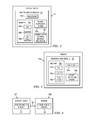
- FIG. 3 is a simplified block diagram illustrating one possible set of details associated with energy management system 10 .
- FIG. 3 includes modem 26 a .
- Modem 26 a may include modem energy module 36 , which includes a processor 35 b , a memory 38 b , and a packet inspection engine 40 b .
- Memory 38 b includes an ACL 44 b , a buffer 46 b , and a link state 48 b .
- ACL 44 b can include one or more ACLs.
- Buffer 46 b can include one or more buffers in particular implementations of the present disclosure.
- modem energy module 36 can be configured to communicate with access router 22 to shift from one power state to a different power state. More specifically, modem energy module 36 can use ACL 44 b to identify important data when making decisions about the desired power saving state of modem 26 a . Modem energy module 34 can buffer important data in buffer 46 b while modem 26 a is in a reduced power state to minimize data loss.
- ACL 44 b in modem energy module 36 can be configured with one or more upstream and downstream ACLs, and optionally with a rate threshold for each ACL.
- Each ACL may include expressions to match traffic at OSI Layer 2, Layer 3, Layer 4, or any suitable combination thereof.
- modem energy module 36 can be configured to monitor the aggregate data rate used by modem 26 a and adjust downstream/upstream channel allocation accordingly. By consolidating traffic on fewer channels, modem energy module 36 can be configured to make a tradeoff between traffic engineering efficiency and modem 26 a power consumption. This may be beneficial when the overall network usage is low.
- modem 26 a may request a smaller channel set based on information from CPE 30 or an end user.
- Buffer 46 b may help avoid data loss while in these power savings modes, making the power saving system invisible (or somewhat seamless) to the end users of the system.
- Buffer 46 b can be used to buffer data in the upstream direction matching the ACLs. In the upstream data flow, when data is important (i.e., matches an entry in ACL 44 b ) and cannot be delivered to access router 22 , the data can be placed in buffer 46 b . Modem 26 a can continue to buffer data for access router 22 until modem 26 a is back into full service mode (either by waking up or by increasing the number of channels allocated to it). Buffering can allow the power savings to occur transparently, without other network elements being aware of it at all.
- Packet inspection engine 40 b can be configured to inspect each packet in upstream and downstream traffic and determine the type of data in each packet.
- ACL 44 b can be used to identify important upstream data such as: messages from the CableCARD to the CA System (e.g., DNCS), outgoing phone calls, download triggers, etc. If modem 26 a is indiscriminately woken up every time a low value message needs to be sent, then modem 26 a will have very few opportunities to conserve power. Hence, a wakeup or increase the allocated channels may be triggered only for certain critical functions.
- FIG. 4 is a simplified block diagram illustrating one possible set of details associated with energy management system 10 .
- FIG. 4 includes access router 22 and modem 26 a .
- Access router 22 includes router energy module 34 .
- Modem 26 a includes modem energy module 36 .
- Access router 22 and modem 26 a are linked together using communication path 50 .
- Communication path 50 may include several different channels that can be used to communicate with one or more modems.
- Access router 22 can be configured to monitor the aggregate data rate used by modem 26 a and adjust downstream/upstream channel allocation accordingly. In aggressive power savings modes, access router 22 may only allocate enough channels for important data and data loss would occur for unimportant data.
- access router 22 may reduce the channels allocated to cable modems based on its own power-savings needs (e.g., a brownout). Access router 22 may also adjust the allocated channels to achieve power savings on access router 22 itself in combination with power savings on the cable modems. If enough cable modems have low bandwidth utilization, and aggregate bandwidth utilization is also low, access router 22 may choose to assign channels to the cable modems such that access router 22 can shut down some channels or ports and, thereby, reduce energy consumption of access router 22 .
- FIG. 5 is a simplified flowchart 500 illustrating example activities for conserving power in an access network.
- the data rate of traffic to a modem is monitored.
- router energy module 34 in access router 22 may monitor the data rate of traffic to modem 26 a .
- modem energy module 36 in modem 26 a may monitor the data rate of traffic to modem 26 a .
- the system determines if the data rate of matching traffic to the modem is below a threshold. For example, the data rate of traffic that matches an entry in an ACL that is related to the modem may be below a data rate threshold.
- the system returns to 502 and the data rate of traffic to the modem is monitored. If the data rate of matching traffic to the modem is below a threshold, then the modem enters into an energy saving mode, as in 506 . For example, if the data rate of traffic to modem 26 a is below a threshold, then energy state control message generator 42 in router energy module 34 may communicate a message (using communication path 50 ) to modem 26 a to enter into an energy saving mode. In another example, if the data rate of traffic to modem 26 a is below a threshold, then modem energy module 36 may request modem 26 a to enter into an energy saving mode.
- FIG. 6 is a simplified flowchart 600 illustrating example activities for conserving power in a network.
- the system determines if a predetermined amount of time has passed without satisfying a condition. For example, the system may not receive any important data (e.g., data that matches an entry in an ACL that is related to a modem) within a predetermined amount of time. If a predetermined amount of time has passed without satisfying a condition, then a request is sent to a modem to enter into an energy saving state, as illustrated at 608 . If a predetermined amount of time has not passed without satisfying a condition, then a traffic flow is received, as illustrated at 604 .
- any important data e.g., data that matches an entry in an ACL that is related to a modem
- the system determines if a packet in the traffic flow matches an entry in an ACL that is related to a modem. For example, packet inspection engine 40 a may inspect a packet in the traffic flow and router energy module 34 may determine if the packet matches an entry in ACL 44 a that is related to modem 26 a . If the packet in the traffic flow does not match an entry in an ACL that is related to a modem, then packets that are destined for the modem are sent to the modem, as illustrated at 614 , and the system determines if a predetermined amount of time has passed without satisfying a condition, as illustrated at 602 . If the packet in the traffic flow does match an entry in an ACL that is related to a modem, then a counter is updated, as illustrated at 610 . For example, a counter that determines the predetermined amount of time may be updated.
- the system determines if a rate threshold is satisfied. If the rate threshold is not satisfied, then packets that are destined for the modem are sent to the modem, as illustrated at 614 , and the system determines if a predetermined amount of time has passed without satisfying a condition, as illustrated at 602 . If the rate threshold is satisfied, then a timer is reset, as illustrated at 616 . The timer may be used to determine if a predetermined amount of time has passed, as illustrated at 602 . At 614 , packets that are destined for the modem are sent to the modem and the system determines if a predetermined amount of time has passed without satisfying a condition, as illustrated at 602 .
- FIG. 7 is a simplified flowchart 700 illustrating example activities for conserving power in a DOCSIS network.
- a packet for a modem is received at a router.
- the system determines if the modem is in a standby state. If the modem is in a standby state, then the system determines if the modem should wake-up to receive the packet, as illustrated at 706 .
- packet inspection engine 40 a may inspect the packet and if the packet matches an entry in ACL 44 a then modem 26 a should wake-up, if the packet does not match an entry in ACL 44 a , then modem 26 a should not wake-up. If the modem should not wake-up to receive the packet, then the packet is discarded, as in 708 .
- the packet is placed in a buffer and the modem is woken up, as illustrated at 710 .
- the packet may be placed in buffer 46 a and energy state control message generator 42 in router energy module 34 may communicate a message (using communication path 50 ) to modem 26 a to wake-up.
- the buffered packet is sent to the modem.
- the system determines if the data rate to the modem is reduced.
- the data rate (e.g., number of channels) on communication path 50 to modem 26 a may have been reduced.) If the data rate to the modem is not reduced, then the packet is sent to the modem, as in 722 . If the data rate to the modem is reduced, then the system determines if the data rate should be increased to receive the packet, as in 716 . For example, packet inspection engine 40 a may inspect the packet and if the packet matches an entry in ACL 44 a , then the data rate should be increased.
- the packet is sent to the modem, as in 722 . Even though the data rate is reduced, delivery of the packet is attempted on a “best effort” basis and it does not matter if the packet is delivered, dropped, discarded, etc. If the data rate should be increased to receive the packet, then the packet is placed in a buffer and the data rate is increased, as illustrated at 718 . At 720 , after the date rate is increased, the buffered packet is sent to the modem.
- a network element can include software to achieve the energy management operations, as outlined herein in this document.
- the energy management functions outlined herein may be implemented by logic encoded in one or more tangible media (e.g., embedded logic provided in an application specific integrated circuit [ASIC], digital signal processor [DSP] instructions, software [potentially inclusive of object code and source code] to be executed by a processor [processors 36 a shown in FIG. 2 and processor 35 b shown in FIG. 3 ], or other similar machine, etc.).
- ASIC application specific integrated circuit
- DSP digital signal processor
- a memory element memory 38 a shown in FIG. 2 and memory 38 b shown in FIG. 3
- the memory element being able to store software, logic, code, or processor instructions that are executed to carry out the activities described in this Specification.
- the processor can execute any type of instructions associated with the data to achieve the operations detailed herein in this Specification.
- the processor could transform an element or an article (e.g., data) from one state or thing to another state or thing.
- the activities outlined herein may be implemented with fixed logic or programmable logic (e.g., software/computer instructions executed by the processor) and the elements identified herein could be some type of a programmable processor, programmable digital logic (e.g., a field programmable gate array [FPGA], an erasable programmable read only memory (EPROM), an electrically erasable programmable ROM (EEPROM)) or an ASIC that includes digital logic, software, code, electronic instructions, or any suitable combination thereof.
- FPGA field programmable gate array
- EPROM erasable programmable read only memory
- EEPROM electrically erasable programmable ROM
- any of these elements can include memory elements for storing information to be used in achieving the energy management activities as outlined herein.
- each of these devices may include a processor that can execute software or an algorithm to perform the energy management activities as discussed in this Specification.
- These devices may further keep information in any suitable memory element [random access memory (RAM), ROM, EPROM, EEPROM, ASIC, etc.], software, hardware, or in any other suitable component, device, element, or object where appropriate and based on particular needs.
- RAM random access memory
- ROM read only memory
- EPROM Erasable programmable read-only memory
- EEPROM electrically erasable programmable read-only memory
- ASIC application specific integrated circuitry
- any of the memory items discussed herein should be construed as being encompassed within the broad term ‘memory element.’
- any of the potential processing elements, modules, and machines described in this Specification should be construed as being encompassed within the broad term ‘processor.’
- Each of the network elements can also include suitable interfaces for receiving, transmitting, and/or otherwise communicating data or information in a network environment.
- energy management system 10 (and its teachings) are readily scalable and, further, can accommodate a large number of components, as well as more complicated/sophisticated arrangements and configurations. Accordingly, the examples provided should not limit the scope or inhibit the broad teachings of energy management system 10 , as potentially applied to a myriad of other architectures.
- energy management system 10 may be applicable to other exchanges and protocols in which data are exchanged in order to provide energy management operations.
- energy management system 10 has been illustrated with reference to particular elements and operations that facilitate the communication process, these elements and operations may be replaced by any suitable architecture or process that achieves the intended functionality of energy management system 10 .
Landscapes
- Engineering & Computer Science (AREA)
- Theoretical Computer Science (AREA)
- General Engineering & Computer Science (AREA)
- Physics & Mathematics (AREA)
- General Physics & Mathematics (AREA)
- Computer Hardware Design (AREA)
- Computing Systems (AREA)
- Data Exchanges In Wide-Area Networks (AREA)
- Small-Scale Networks (AREA)
Abstract
Description
- This application claims the benefit of priority under 35 U.S.C. §119(e) to U.S. Provisional Application Ser. No. 61/588,906, “METHOD TO CONSERVE POWER IN DOCSIS NETWORKS WITHOUT LOSS OF SERVICE QUALITY” filed Jan. 20, 2012, which is hereby incorporated by reference in its entirety.
- This disclosure relates in general to the field of energy and, more particularly, to a system and a method for conserving power in an access network without loss of service quality.
- Modern hardware can generally be placed into various low-power states, where various components may be throttled down or disabled altogether. Certain low-power states cause a total loss of network connectivity for some period of time. This makes low-power features difficult (almost impossible) to use for some devices (e.g., set-top boxes and embedded multimedia terminal adapters (eMTAs) that need continuous uninterrupted access to upstream and/or downstream data). It would be beneficial if power savings strategies could be employed as frequently as possible without interrupting important data flows. It would be a further benefit if a system could make intelligent decisions to minimize the energy consumption, while maximizing the user experience.
- To provide a more complete understanding of the present disclosure and features and advantages thereof, reference is made to the following description, taken in conjunction with the accompanying figures, wherein like reference numerals represent like parts, in which:
-
FIG. 1 is a simplified block diagram of an energy management system in accordance with one embodiment of the present disclosure; -
FIG. 2 is a simplified block diagram illustrating possible example details associated with one embodiment of the present disclosure; -
FIG. 3 is a simplified block diagram illustrating possible example details associated with one embodiment of the present disclosure; -
FIG. 4 is a simplified block diagram illustrating possible example details associated with one embodiment of the present disclosure; -
FIG. 5 is a simplified flow diagram illustrating potential operations associated with one embodiment of the present disclosure; -
FIG. 6 is a simplified flow diagram illustrating potential operations associated with one embodiment of the present disclosure; and -
FIG. 7 is a simplified flow diagram illustrating potential operations associated with one embodiment of the present disclosure. - A method is provided in one example embodiment and includes receiving a first data at a first network element; determining that the first data does not match an entry in an access control list; and sending a first message to a second network element that causes the second network element to enter into a low-power state. In yet another example embodiment, the method can include receiving a second data; determining that the second data matches an entry in the access control list; buffering the second data; sending a second message to the second network element, where the second message causes the second network element to exit the low-power state; and sending the buffered second data to the second network element.
- More specific implementations may include receiving a second data at the first network element, where the second data matches an entry in the access control list; buffering the second data; increasing a number of channels allocated to the second network element; and sending the buffered second data to the second network element. The first network element can be a cable modem termination system (CMTS), and the second network element can be a cable modem (CM). Copies of the access control list are provided in the CMTS and the CM.
-
FIG. 1 is a simplified block diagram of anenergy management system 10 in accordance with one example implementation of the present disclosure.FIG. 1 includesprovisioning servers 12, a network management system (NMS)server 14, an Internet 16, anedge router 18, aservice provider backbone 20, anaccess router 22, anaccess network 24, a plurality of modems 26 a-c, agateway 28, a customer premise equipment (CPE) 30, and anenergy policy server 32. Accessrouter 22 can include arouter energy module 34, and each of the plurality of modems 26 a-c can include amodem energy module 36. - In general terms,
energy management system 10 can be configured to communicate with modems 26 a-c to shift from one power state to a different power state. More specifically,access router 22 and modems 26 a-c can use access control lists (ACLS) to identify important data when making decisions about the desired power saving state of modems 26 a-c. Note that while in the examples discussed herein, an ACL is used as a way to sort or to classify traffic, other methods may equally be used, such as a data over cable service interfaces specification (DOCSIS) classifier, a telecommunications access method (TCAM), etc. If a specific modem (e.g.,modem 26 a) is in a reduced power state,access router 22 and the modem can buffer important data to minimize data loss. Any unimportant data may be ignored or deliberately lost, thereby allowing the modem to remain in a deeper power savings state. In an embodiment, all (or a portion) of the unimportant data can also be buffered. - When the modem exits the power saving state and enters a state that would allow the modem to receive the data,
access router 22 can send the buffered data to the modem. Further, when the modem exits the power saving state, the modem can send any buffered data from the modem to the access router. From a business perspective, the smart loading capabilities of the architecture allow for realizable cost savings. Furthermore,energy management system 10 may provide a mechanism that can identify import data and wake the modem to receive the important data or to send the important data. - In one example implementation, the modem may use a combination of power savings strategies. For example, the modem may utilize duty-cycle based power savings, where the modem moves into a low-power standby state and periodically wakes up to look for a wake-up signal from
access router 22. In another example, the modem may decrease the number of utilized channels and/or transmitters. Further, the modem may enter into a “light sleep” mode, where a single downstream channel remains active and all the other downstream channels and all upstream transmitters are in a standby mode. The single downstream channel can watch for wake-up signals. In addition, the modem may change the modulation profile used for the upstream transmitters, andaccess router 22 may use reduced bitrates and smaller constellations to achieve the same bit error rate while using less transmit power. - For purposes of illustrating certain example techniques of
energy management system 10, it is important to understand howenergy management system 10 conserves power. The following foundational information may be viewed as a basis from which the present disclosure may be properly explained. Such information is offered earnestly for purposes of discussion only and, accordingly, should not be construed in any way to limit the broad scope of the present disclosure. DOCSIS is a telecommunications standard that permits the addition of high-speed data transfer to an existing cable TV (CATV) system. DOCSIS is employed by many cable television operators to provide Internet access over existing hybrid fiber-coaxial (HFC) infrastructure. A DOCSIS architecture generally includes two primary components: a cable modem (CM) located at a customer premises (e.g., more generally represented asmodem 26 a) and a cable modem termination system (CMTS) located at a CATV headend (e.g., more generally represented as access router 22). Cable systems supporting on-demand programming typically use a hybrid fiber-coaxial system. Fiber optic lines bring digital signals to nodes in the system, where they are converted into RF channels and modem signals on coaxial trunk lines. - A DOCSIS cable modem hardware (e.g.,
modem 26 a) can generally be placed into various low-power states, where hardware components may be throttled down or disabled altogether. These hardware components can include a tuner, demodulator, upstream transmitter, main central processing unit (CPU), etc. Some low-power states cause a total loss of network connectivity for some period of time. This makes low-power features difficult or impossible to use for devices like set-top boxes and embedded media terminal adapters (eMTAs) that need continuous uninterrupted access to upstream and/or downstream data. Other low-power states reduce the usable bandwidth available to data consumers. For example, it is desirable for the usable bandwidth to adjust up and down automatically to maximize the potential power savings while minimizing the negative effects to the end user experience. To be effective, these power savings strategies may be employed as frequently as possible without interrupting important data flows. - To identify important data flows, an access router (e.g., access router 22) can be configured with upstream and downstream ACLs. Each ACL may include expressions to match traffic at OSI Layer 2, Layer 3, Layer 4, or any suitable combination thereof. For each modem (e.g., modem 26 a-c) in communication with the access router, the access router can monitor the data rate of packets matching ACLs. In addition, each modem may be used to make decisions about entering or leaving power saving states. In an embodiment, each modem can be provisioned with the same or different ACLs that may or may not contain entries from the ACLs in the access router. In another embodiment, each modem may be provisioned with the same ACLs. The ACLs can include packet matching parameters, rate thresholds, time thresholds, timers, etc.
- Note that DOCSIS Packet Classifiers are functionally equivalent to ACLs in this context. In an embodiment, when implementing the ACLs, packets such as Address Resolution Protocol (ARP) packets can be identified based on parameters such as the target address. An ARP may be filtered based on parameters within the body of the ARP (e.g., a target hardware address). Other network elements performing network traffic shaping functions may also use the ACLs to identify important traffic.
- The access router can be configured to monitor the aggregate data rate used by a cable modem and adjust downstream/upstream channel allocation accordingly. By consolidating traffic on fewer channels, the access router can make a tradeoff between traffic engineering efficiency and modem power consumption. This may be beneficial when the overall network usage is low. Likewise, each modem may request a smaller channel set based on information from a CPE (e.g., CPE 30) or an end user.
- In aggressive power savings modes, the access router may only allocate enough channels for important data and data loss can occur for unimportant data. (Important data can be described by the ACLs.) Likewise, the access router may reduce the channels allocated to one or more modems based on its own power-savings needs (e.g., a brownout). In extreme cases, one or more modems may employ only a single downstream channel and not use a transmitter. In one example, the downstream channel can continue to forward multicast traffic. Each modem can restore the upstream channel upon receiving a signal from the access router or based on the need to forward important data.
- In another example, if all ACLs show a long enough period of inactivity, each modem may be placed into a standby mode, where no data can be sent or received until the access router sends a wake-up signal. For all the modems connected to the access router, the wake-up signal can optionally indicate which specific modems have data pending at the access router. In an embodiment, the wake-up signal may be delivered using a DOCSIS Media Access Control (MAC) Management Message, so the wake-up process can be effective even if a modem does not have an IP address.
- Once a modem has been placed into a standby mode, it can remain there until data for the modem matches the ACLs in either the access router or the modem. In one example, the access router can monitor the downstream ACLs and their associated rate thresholds, while the modem can monitor the ACLs applicable to a user network port. Once the important data exceeds a threshold, the access router may send a wakeup signal to the modem, or the modem may initiate a wakeup with the access router. Upon waking up, the modem can use a wake-on-LAN or similar feature to wake the attached CPE devices (e.g., CPE 30) that will receive important data.
- The access router can be configured to take into account the power savings mode of different modems when it makes decisions such as modem load balancing. The access router may also take into account the power savings capabilities of each modem when assigning each modem to specific channels. By taking into account the power savings capabilities of each modem, the current power savings mode that each modem is in, the tier of service for each modem, and/or the current congestion levels on the network, the access router can make intelligent decisions to minimize the energy consumption of each modem and the access router while maximizing the user experience.
- The access router can also be configured to have the capability to force all the modems into certain energy savings modes under certain conditions, such as during brownouts. The access router may also adjust the allocated channels to achieve power savings on the access router itself in combination with power savings on the modems. If enough modems have low bandwidth utilization and aggregate bandwidth utilization is also low, the access router may choose to assign specific channels to each modem such that the access router can shut down some channels or ports and, thereby, reduce energy consumption of the access router.
- In an embodiment,
energy management system 10 can be configured to allow an end user to control the power dissipation policies of a modem, behaviors that have side effects on the user's experience of delivered services to the modem, and to allow changes to the modem's operating states to be initiated by the end user. In addition,energy management system 10 can be configured by the network and service provider to control the modem's terminal power dissipation policies and behaviors and to allow changes to the modem's operating states to be initiated by application software. In another embodiment,energy management system 10 can inhibit false alarms from network element management systems that might respond to low-power dissipation states of the modem as if they were fault conditions. For example, if network elements (e.g., modems 26 a-c) are in a low-power state, a fault condition could be triggered due to packet loss. - Applications running on a CPE can initiate two-way network communications in response to user interaction and autonomously generated events. Network management systems (e.g., provisioning
servers 12,NMS server 14,energy policy server 32, etc.) can initiate two-way network communications to agent processes in the CPE. Two-way communications generally have unicast IP source and destination addresses. Often, network management systems repeatedly transmit certain types of information in structures called data carousels. Data carousels may be addressed to broadcast or multicast destinations. Data carousels usually convey information that is needed by the CPE, but that is unsuitable for storage in the CPE's persistent memory. For instance, if the CPE is a set-top box, system information and program guide information changes occasionally and this information would not be reliable when the set-top box activates after a significant time offline. Carousels deliver data with performance independent of the number of set-top boxes served. In addition, broadcast carousels can remain effective in some situations, where upstream communications are impaired. - Several element management and provisioning protocols may use downstream datagram delivery that terminate at the CPE. Some of these datagrams may be unsolicited by the CPE and do not result in any attempt to respond with an acknowledgement. Examples include conditional access Entitlement Management Messages and MPEG DSM-CC passthrough messages when the CPE is a set-top box.
- For a low-power dissipation state in which a modem ceases to act on DOCSIS station maintenance opportunities, rapid resumption of a two-way IP data forwarding service is desired when exiting a low-power dissipation state. DOCSIS 1.0/1.1/2.0/3.0 systems typically take 15 to 60 seconds to complete the re-initialization and registration process. Registration delays suffer contributions from the modem, the access routers, servers, etc.
Energy management system 10 can be configured to allow these elements to remain synchronized such that a return to full modem operation takes no more than several hundred milliseconds. - The modem might need to maintain values in memory including IP addresses, configuration file settings, service identifier (SID) values, downstream service identifier (DSID) values, service agreement identifier (SAID), BPI+ state, etc. The modem can be configured to keep track of elapsed time. In one example, the modem may be free from having to maintain autonomous tracking of elapsed time during a low-power dissipation state, even though some set-top boxes support scheduled events.
- The modem can be configured to send messages that signal entry into a low-power dissipation state and indicate which modem activities that are normally visible are now being suspended. For example, when the modem registers with the network, a server sends a configuration file to the modem. In response, the modem constructs a REG-REQ, REG-REQ-MP, REG-RSP, REG-RSP-MP, etc. message including indications of the modem's capabilities and then sends the message to the access router. The access router can send a REG-RSP, REG-RSP-MP, etc. message to the modem to indicate the modes to be engaged.
- In an embodiment, messages from the network to the modem or CPE can be used to communicate policies such as duty cycle, always-be-on time window, whether the downstream receiver should continue to listen for control messages, etc. Policies of direct interest to the access router may be indicated in extensions in REG-REQ, REG-REQ-MP, REG-RSP and REG-RSP-MP DOCSIS MAC Management messages. The modem and the access router can implement these policies only partially and, thus, may need to be discovered or negotiated. In another embodiment, the ranging operations of the modem may be reduced when coming out of a low-power state. For example, the access router may continue to offer station maintenance opportunities so that the modem can go directly to station maintenance and skip initial maintenance.
- In one example, RNG-REQ and RNG-RSP messages can be extended to convey an exchange. More specifically, the modem may send a message indicating, “Entering low-power mode now.” In response, the access router may send a message indicating, “Acknowledged, return for station maintenance in no longer than X seconds.” In another example, a RNG-RSP message may be extended to convey a future time interval over which the next MAP with a station maintenance opportunity would occur so the modem can wake-up just for the maintenance opportunity.
- In addition, the RNG-RSP message may be extended to express a signal from the access router to the modem commanding “wake-up for sustained downstream reception for an interval of no less than X seconds,” or to separately express “wake-up for two-way operation.” The downstream-only reception can be useful if an application needed to push DSG or multicast content like system information or program guide tables.
- In one non-limiting example, the modem can continue to be aware of the passage of time in suspended operation modes, with a resolution no coarser than 10 milliseconds. The modem may also consider the uncertainty in its own timekeeping when scheduling future events so that needed wake-up activities sufficiently precede the events of concern. The modem may cease to maintain its local replica of a SYNC time counter during suspended operation modes. Upon waking from a suspended operation mode, the modem can continue using all attributes and parameters that were obtained from the DHCP process if the DHCP lease (or DHCPv6 lease and router advertisement lifetime) has not expired.
- Turning to the example infrastructure associated with present disclosure,
CPE 30 can be associated with devices, customers, or end users wishing to receive data or content inenergy management system 10 via some network. The term ‘customer premise equipment’ is inclusive of devices used to initiate a communication, such as a receiver, a computer, a set-top box, an Internet radio device (IRD), a cell phone, a smart phone, a tablet, a personal digital assistant (PDA), a Google Android, an iPhone, and iPad, or any other device, component, element, or object capable of initiating voice, audio, video, media, or data exchanges withinenergy management system 10.CPE 30 may also be inclusive of a suitable interface to the human user, such as a display, a keyboard, a touchpad, a remote control, or other terminal equipment.CPE 30 may also be any device that seeks to initiate a communication on behalf of another entity or element, such as a program, a database, or any other component, device, element, or object capable of initiating an exchange withinenergy management system 10. Data, as used herein in this document, refers to any type of numeric, voice, video, media, or script data, or any type of source or object code, or any other suitable information in any appropriate format that may be communicated from one point to another. -
Service provider backbone 20 andaccess network 24 each represent a series of points or nodes of interconnected communication paths for receiving and transmitting packets of information that propagate throughenergy management system 10.Service provider backbone 20 andaccess network 24 each offer a communicative interface between sources and/or hosts, and may be any local area network (LAN), wireless local area network (WLAN), metropolitan area network (MAN), Intranet, Extranet, WAN, virtual private network (VPN), or any other appropriate architecture or system that facilitates communications in a network environment. A network can comprise any number of hardware or software elements coupled to (and in communication with) each other through a communications medium. - In one particular instance, the architecture of the present disclosure can be associated with a service provider digital subscriber line (DSL) deployment. In other examples, the architecture of the present disclosure would be equally applicable to other communication environments, such as an enterprise wide area network (WAN) deployment, cable scenarios, broadband generally, fixed wireless instances, fiber to the x (FTTx), which is a generic term for any broadband network architecture that uses optical fiber in last-mile architectures, and DOCSIS cable television (CATV). The architecture of the present disclosure may include a configuration capable of transmission control protocol/internet protocol (TCP/IP) communications for the transmission and/or reception of packets in a network.
-
Access router 22 and modem 26 a-c are network elements that can facilitate the power management activities discussed herein. As used herein in this Specification, the term ‘network element’ is meant to encompass any of the aforementioned elements, as well as switches, cable boxes of any kind (including set-top boxes), CMTSs, CMs, gateways, bridges, load balancers, firewalls, inline service nodes, proxies, servers, processors, modules, or any other suitable device, component, element, proprietary appliance, or object operable to exchange information in a network environment. These network elements may include any suitable hardware, software, components, modules, interfaces, or objects that facilitate the operations thereof. This may be inclusive of appropriate algorithms and communication protocols that allow for the effective exchange of data or information. - In one implementation,
access router 22 and/ormodem 26 a include software to achieve (or to foster) the power management activities discussed herein. This could include the implementation of instances of initializationrouter energy module 34 and/ormodem energy module 36. Additionally, each of these elements can have an internal structure (e.g., a processor, a memory element, etc.) to facilitate some of the operations described herein. In other embodiments, these energy management activities may be executed externally to these elements, or included in some other network element to achieve the intended functionality. Alternatively,access router 22 and/ormodem 26 a may include software (or reciprocating software) that can coordinate with other network elements in order to achieve the power energy management activities described herein. In still other embodiments, one or several devices may include any suitable algorithms, hardware, software, components, modules, interfaces, or objects that facilitate the operations thereof. - Turning to
FIG. 2 ,FIG. 2 is a simplified block diagram illustrating one possible set of details associated withenergy management system 10.FIG. 2 includesaccess router 22 that includesrouter energy module 34, which includes aprocessor 35 a, amemory 38 a, apacket inspection engine 40 a, and an energy statecontrol message generator 42.Memory 38 a includes anACL 44 a, abuffer 46 a, and alink state 48 a.ACL 44 a can include one or more ACLs.Buffer 46 a can include one or more buffers. - In an example implementation,
router energy module 34 may be configured to communicate withmodem 26 a (ormodems router energy module 34 can useACL 44 a to identify important data when making decisions about the desired power saving state ofmodem 26 a. In addition,router energy module 34 can buffer important data inbuffer 46 awhile modem 26 a is in a reduced power state to minimize data loss. - In an embodiment,
ACL 44 a inrouter energy module 34 can be configured with one or more upstream and downstream ACLs, and optionally with a rate threshold for each ACL. Each ACL may include expressions to match traffic at OSI Layer 2, Layer 3, Layer 4, or any suitable combination thereof. In addition,router energy module 34 can be configured to monitor the aggregate data rate connected to ACLs and/or used bymodem 26 a and adjust downstream/upstream channel allocation accordingly. Further, by consolidating traffic on fewer channels,router energy module 34 can be configured to make a tradeoff between traffic engineering efficiency andmodem 26 a power consumption, which may be beneficial when the overall network usage is low. Likewise,modem 26 a may request a smaller channel set based on information fromCPE 30 or an end user. If aggregate data rates are low,access router 22 can askmodem 26 a to drop down to a smaller number of channels in order to turn off some channels onaccess router 22 and, thereby, reduce power consumption ofaccess router 22. -
Router energy module 34 can be configured to take into account the power savings mode of different modems 26 a-c when it makes decisions such as modem load balancing.Router energy module 34 may also take into account the power savings capabilities of each modem when assigning specific channels to each modem. By taking into account the power savings capabilities ofmodem 26 a, the current power savings mode thatmodem 26 a is in, the tier of service formodem 26 a, and/or the current congestion levels on the network,router energy module 34 can make intelligent decisions to minimize the energy consumption ofmodem 26 a andaccess router 22 while maximizing the user experience. -
Buffer 46 a may help avoid data loss whilemodem 26 a is in a power savings mode, thus making the power saving system invisible (or somewhat seamless) to the end users. In the downstream traffic flow, when data is important (i.e., matches an entry inACL 44 a) and cannot be delivered tomodem 26 a, the data can be placed inbuffer 46 a.Access router 22 can continue to buffer data formodem 26 a until it can bringmodem 26 a back into full service mode (either by sending it a wakeup signal or by increasing the number of channels allocated to it). In one example,modem 26 a may not need to go back into full service mode and may (instead) move into any mode that provides sufficient connectivity to allow the buffered data to be delivered tomodem 26 a. - In one embodiment, an operator or subscriber may want to discard large amounts of unimportant data at certain times to maximize power savings. To facilitate such an action, the subscriber may push a “deep sleep” button on
modem 26 a that prevents all normal Internet access (e.g., web browsing), but that still allows essential services like VOIP to work normally. Buffering can allow the power savings mode to occur transparently without other network elements being aware of the power saving mode. More specifically, in a set-top network, a headend controller (e.g., Digital Network Control System (DNCS)) periodically sends messages called Entitlement Management Messages (EMMs) in the downstream traffic flow. These messages update entitlements and keys used to decrypt protected content. If multiple EMM refreshes are missed, the set-top will no longer be able to view protected content. With buffering, the EMMs can be delivered even whenmodem 26 a is in a low-power mode (e.g., sleeping). The DNCS does not have to be aware of modem's 26 power savings state. Likewise, buffering allows TCP keepalives to be delivered, allowing TCP sessions to remain alive across an otherwise sleepingmodem 26 a. -
Packet inspection engine 40 a can be configured to inspect each packet in upstream and downstream traffic to determine the type of data in each packet.ACL 44 a can be used to identify important downstream data such as: EMM messages to CableCARDs, incoming phone calls, TCP keepalives (for idle sessions), SNMP polls from the headends, download triggers, etc. Because the downstream traffic flow is flooded with a barrage of low value data such as ARP messages, Neighbor Discovery messages, port scans, attempted TCP connections for non-critical services, spam email delivery, etc., a wakeup or increase in the allocated channels can be triggered only for critical functions. Ifmodem 26 a is indiscriminately woken up every time such a low value message arrives, thenmodem 26 a will have very few opportunities to conserve power. For example, ARPs alone typically arrive at a high rate on the DOCSIS downstream on production headends and a large amount of bandwidth could be consumed by the constant handshaking betweenaccess router 22 andmodem 26 a to movemodem 26 a into a sleep mode and subsequently wake it back up again. Energy statecontrol message generator 42 can be configured to optimally communicate messages tomodem 26 a. - Turning to
FIG. 3 ,FIG. 3 is a simplified block diagram illustrating one possible set of details associated withenergy management system 10.FIG. 3 includesmodem 26 a.Modem 26 a may includemodem energy module 36, which includes aprocessor 35 b, amemory 38 b, and apacket inspection engine 40 b.Memory 38 b includes anACL 44 b, abuffer 46 b, and alink state 48 b.ACL 44 b can include one or more ACLs.Buffer 46 b can include one or more buffers in particular implementations of the present disclosure. - In an example implementation,
modem energy module 36 can be configured to communicate withaccess router 22 to shift from one power state to a different power state. More specifically,modem energy module 36 can useACL 44 b to identify important data when making decisions about the desired power saving state ofmodem 26 a.Modem energy module 34 can buffer important data inbuffer 46 b whilemodem 26 a is in a reduced power state to minimize data loss. - In an embodiment,
ACL 44 b inmodem energy module 36 can be configured with one or more upstream and downstream ACLs, and optionally with a rate threshold for each ACL. Each ACL may include expressions to match traffic at OSI Layer 2, Layer 3, Layer 4, or any suitable combination thereof. In addition,modem energy module 36 can be configured to monitor the aggregate data rate used bymodem 26 a and adjust downstream/upstream channel allocation accordingly. By consolidating traffic on fewer channels,modem energy module 36 can be configured to make a tradeoff between traffic engineering efficiency andmodem 26 a power consumption. This may be beneficial when the overall network usage is low. Likewise,modem 26 a may request a smaller channel set based on information fromCPE 30 or an end user. -
Buffer 46 b may help avoid data loss while in these power savings modes, making the power saving system invisible (or somewhat seamless) to the end users of the system.Buffer 46 b can be used to buffer data in the upstream direction matching the ACLs. In the upstream data flow, when data is important (i.e., matches an entry inACL 44 b) and cannot be delivered to accessrouter 22, the data can be placed inbuffer 46 b.Modem 26 a can continue to buffer data foraccess router 22 untilmodem 26 a is back into full service mode (either by waking up or by increasing the number of channels allocated to it). Buffering can allow the power savings to occur transparently, without other network elements being aware of it at all. -
Packet inspection engine 40 b can be configured to inspect each packet in upstream and downstream traffic and determine the type of data in each packet.ACL 44 b can be used to identify important upstream data such as: messages from the CableCARD to the CA System (e.g., DNCS), outgoing phone calls, download triggers, etc. Ifmodem 26 a is indiscriminately woken up every time a low value message needs to be sent, thenmodem 26 a will have very few opportunities to conserve power. Hence, a wakeup or increase the allocated channels may be triggered only for certain critical functions. - Turning to
FIG. 4 ,FIG. 4 is a simplified block diagram illustrating one possible set of details associated withenergy management system 10.FIG. 4 includesaccess router 22 andmodem 26 a.Access router 22 includesrouter energy module 34.Modem 26 a includesmodem energy module 36.Access router 22 andmodem 26 a are linked together usingcommunication path 50.Communication path 50 may include several different channels that can be used to communicate with one or more modems.Access router 22 can be configured to monitor the aggregate data rate used bymodem 26 a and adjust downstream/upstream channel allocation accordingly. In aggressive power savings modes,access router 22 may only allocate enough channels for important data and data loss would occur for unimportant data. Likewise,access router 22 may reduce the channels allocated to cable modems based on its own power-savings needs (e.g., a brownout).Access router 22 may also adjust the allocated channels to achieve power savings onaccess router 22 itself in combination with power savings on the cable modems. If enough cable modems have low bandwidth utilization, and aggregate bandwidth utilization is also low,access router 22 may choose to assign channels to the cable modems such thataccess router 22 can shut down some channels or ports and, thereby, reduce energy consumption ofaccess router 22. - Turning to
FIG. 5 ,FIG. 5 is asimplified flowchart 500 illustrating example activities for conserving power in an access network. At 502, the data rate of traffic to a modem is monitored. For example,router energy module 34 inaccess router 22 may monitor the data rate of traffic tomodem 26 a. In another example,modem energy module 36 inmodem 26 a may monitor the data rate of traffic tomodem 26 a. At 504, the system determines if the data rate of matching traffic to the modem is below a threshold. For example, the data rate of traffic that matches an entry in an ACL that is related to the modem may be below a data rate threshold. If the data rate of matching traffic to the modem is not below a data rate threshold, then the system returns to 502 and the data rate of traffic to the modem is monitored. If the data rate of matching traffic to the modem is below a threshold, then the modem enters into an energy saving mode, as in 506. For example, if the data rate of traffic tomodem 26 a is below a threshold, then energy statecontrol message generator 42 inrouter energy module 34 may communicate a message (using communication path 50) tomodem 26 a to enter into an energy saving mode. In another example, if the data rate of traffic tomodem 26 a is below a threshold, thenmodem energy module 36 may requestmodem 26 a to enter into an energy saving mode. - Turning to
FIG. 6 ,FIG. 6 is asimplified flowchart 600 illustrating example activities for conserving power in a network. At 602, the system determines if a predetermined amount of time has passed without satisfying a condition. For example, the system may not receive any important data (e.g., data that matches an entry in an ACL that is related to a modem) within a predetermined amount of time. If a predetermined amount of time has passed without satisfying a condition, then a request is sent to a modem to enter into an energy saving state, as illustrated at 608. If a predetermined amount of time has not passed without satisfying a condition, then a traffic flow is received, as illustrated at 604. - At 606, the system determines if a packet in the traffic flow matches an entry in an ACL that is related to a modem. For example,
packet inspection engine 40 a may inspect a packet in the traffic flow androuter energy module 34 may determine if the packet matches an entry inACL 44 a that is related tomodem 26 a. If the packet in the traffic flow does not match an entry in an ACL that is related to a modem, then packets that are destined for the modem are sent to the modem, as illustrated at 614, and the system determines if a predetermined amount of time has passed without satisfying a condition, as illustrated at 602. If the packet in the traffic flow does match an entry in an ACL that is related to a modem, then a counter is updated, as illustrated at 610. For example, a counter that determines the predetermined amount of time may be updated. - At 612, the system determines if a rate threshold is satisfied. If the rate threshold is not satisfied, then packets that are destined for the modem are sent to the modem, as illustrated at 614, and the system determines if a predetermined amount of time has passed without satisfying a condition, as illustrated at 602. If the rate threshold is satisfied, then a timer is reset, as illustrated at 616. The timer may be used to determine if a predetermined amount of time has passed, as illustrated at 602. At 614, packets that are destined for the modem are sent to the modem and the system determines if a predetermined amount of time has passed without satisfying a condition, as illustrated at 602.
- Turning to
FIG. 7 ,FIG. 7 is asimplified flowchart 700 illustrating example activities for conserving power in a DOCSIS network. At 702, a packet for a modem is received at a router. At 704, the system determines if the modem is in a standby state. If the modem is in a standby state, then the system determines if the modem should wake-up to receive the packet, as illustrated at 706. For example,packet inspection engine 40 a may inspect the packet and if the packet matches an entry inACL 44 a thenmodem 26 a should wake-up, if the packet does not match an entry inACL 44 a, thenmodem 26 a should not wake-up. If the modem should not wake-up to receive the packet, then the packet is discarded, as in 708. - If the modem should wake-up, then the packet is placed in a buffer and the modem is woken up, as illustrated at 710. For example, if
modem 26 a should wake-up, then the packet may be placed inbuffer 46 a and energy statecontrol message generator 42 inrouter energy module 34 may communicate a message (using communication path 50) tomodem 26 a to wake-up. At 712, after the modem is awake, the buffered packet is sent to the modem. Referring to 704, if the modem is not in a standby state, then the system determines if the data rate to the modem is reduced. (Before the packet was received, the data rate (e.g., number of channels) oncommunication path 50 tomodem 26 a may have been reduced.) If the data rate to the modem is not reduced, then the packet is sent to the modem, as in 722. If the data rate to the modem is reduced, then the system determines if the data rate should be increased to receive the packet, as in 716. For example,packet inspection engine 40 a may inspect the packet and if the packet matches an entry inACL 44 a, then the data rate should be increased. - If the data rate should not be increased to receive the packet, then the packet is sent to the modem, as in 722. Even though the data rate is reduced, delivery of the packet is attempted on a “best effort” basis and it does not matter if the packet is delivered, dropped, discarded, etc. If the data rate should be increased to receive the packet, then the packet is placed in a buffer and the data rate is increased, as illustrated at 718. At 720, after the date rate is increased, the buffered packet is sent to the modem.
- As identified previously, a network element can include software to achieve the energy management operations, as outlined herein in this document. In certain example implementations, the energy management functions outlined herein may be implemented by logic encoded in one or more tangible media (e.g., embedded logic provided in an application specific integrated circuit [ASIC], digital signal processor [DSP] instructions, software [potentially inclusive of object code and source code] to be executed by a processor [processors 36 a shown in
FIG. 2 andprocessor 35 b shown inFIG. 3 ], or other similar machine, etc.). In some of these instances, a memory element [memory 38 a shown inFIG. 2 andmemory 38 b shown inFIG. 3 ] can store data used for the operations described herein. This includes the memory element being able to store software, logic, code, or processor instructions that are executed to carry out the activities described in this Specification. The processor can execute any type of instructions associated with the data to achieve the operations detailed herein in this Specification. In one example, the processor could transform an element or an article (e.g., data) from one state or thing to another state or thing. In another example, the activities outlined herein may be implemented with fixed logic or programmable logic (e.g., software/computer instructions executed by the processor) and the elements identified herein could be some type of a programmable processor, programmable digital logic (e.g., a field programmable gate array [FPGA], an erasable programmable read only memory (EPROM), an electrically erasable programmable ROM (EEPROM)) or an ASIC that includes digital logic, software, code, electronic instructions, or any suitable combination thereof. - Any of these elements (e.g., the network elements, etc.) can include memory elements for storing information to be used in achieving the energy management activities as outlined herein. Additionally, each of these devices may include a processor that can execute software or an algorithm to perform the energy management activities as discussed in this Specification. These devices may further keep information in any suitable memory element [random access memory (RAM), ROM, EPROM, EEPROM, ASIC, etc.], software, hardware, or in any other suitable component, device, element, or object where appropriate and based on particular needs. Any of the memory items discussed herein should be construed as being encompassed within the broad term ‘memory element.’ Similarly, any of the potential processing elements, modules, and machines described in this Specification should be construed as being encompassed within the broad term ‘processor.’ Each of the network elements can also include suitable interfaces for receiving, transmitting, and/or otherwise communicating data or information in a network environment.
- Note that with the examples provided above, interaction may be described in terms of two, three, or four network elements. However, this has been done for purposes of clarity and example only. In certain cases, it may be easier to describe one or more of the functionalities of a given set of flows by only referencing a limited number of network elements. It should be appreciated that energy management system 10 (and its teachings) are readily scalable and, further, can accommodate a large number of components, as well as more complicated/sophisticated arrangements and configurations. Accordingly, the examples provided should not limit the scope or inhibit the broad teachings of
energy management system 10, as potentially applied to a myriad of other architectures. - It is also important to note that the steps in the preceding FIGURES illustrate only some of the possible scenarios that may be executed by, or within,
energy management system 10. Some of these steps may be deleted or removed where appropriate, or these steps may be modified or changed considerably without departing from the scope of the present disclosure. In addition, a number of these operations have been described as being executed concurrently with, or in parallel to, one or more additional operations. However, the timing of these operations may be altered considerably. The preceding operational flows have been offered for purposes of example and discussion. Substantial flexibility is provided byenergy management system 10 in that any suitable arrangements, chronologies, configurations, and timing mechanisms may be provided without departing from the teachings of the present disclosure. - Although the present disclosure has been described in detail with reference to particular arrangements and configurations, these example configurations and arrangements may be changed significantly without departing from the scope of the present disclosure. For example, although the present disclosure has been described with reference to particular communication exchanges involving certain protocols (e.g., TCP/IP, ARP, UDP, SNMP, etc.),
energy management system 10 may be applicable to other exchanges and protocols in which data are exchanged in order to provide energy management operations. In addition, althoughenergy management system 10 has been illustrated with reference to particular elements and operations that facilitate the communication process, these elements and operations may be replaced by any suitable architecture or process that achieves the intended functionality ofenergy management system 10. - Numerous other changes, substitutions, variations, alterations, and modifications may be ascertained to one skilled in the art and it is intended that the present disclosure encompass all such changes, substitutions, variations, alterations, and modifications as falling within the scope of the appended claims. In order to assist the United States Patent and Trademark Office (USPTO) and, additionally, any readers of any patent issued on this application in interpreting the claims appended hereto, Applicant wishes to note that the Applicant: (a) does not intend any of the appended claims to invoke paragraph six (6) of 35 U.S.C. section 112 as it exists on the date of the filing hereof unless the words “means for” or “step for” are specifically used in the particular claims; and (b) does not intend, by any statement in the specification, to limit this disclosure in any way that is not otherwise reflected in the appended claims.
Claims (20)
Priority Applications (1)
| Application Number | Priority Date | Filing Date | Title |
|---|---|---|---|
| US13/624,849 US9141169B2 (en) | 2012-01-20 | 2012-09-21 | System and method to conserve power in an access network without loss of service quality |
Applications Claiming Priority (2)
| Application Number | Priority Date | Filing Date | Title |
|---|---|---|---|
| US201261588906P | 2012-01-20 | 2012-01-20 | |
| US13/624,849 US9141169B2 (en) | 2012-01-20 | 2012-09-21 | System and method to conserve power in an access network without loss of service quality |
Publications (2)
| Publication Number | Publication Date |
|---|---|
| US20130191663A1 true US20130191663A1 (en) | 2013-07-25 |
| US9141169B2 US9141169B2 (en) | 2015-09-22 |
Family
ID=48798241
Family Applications (1)
| Application Number | Title | Priority Date | Filing Date |
|---|---|---|---|
| US13/624,849 Active 2033-06-03 US9141169B2 (en) | 2012-01-20 | 2012-09-21 | System and method to conserve power in an access network without loss of service quality |
Country Status (1)
| Country | Link |
|---|---|
| US (1) | US9141169B2 (en) |
Cited By (16)
| Publication number | Priority date | Publication date | Assignee | Title |
|---|---|---|---|---|
| US20140006816A1 (en) * | 2012-06-29 | 2014-01-02 | Fujitsu Limited | Control apparatus, control method, and computer product |
| US20140086128A1 (en) * | 2012-09-26 | 2014-03-27 | Broadcom Corporation | Power savings within communication systems |
| US20140269470A1 (en) * | 2013-03-15 | 2014-09-18 | Time Warner Cable Enterprises Llc | Apparatus and method for reducing power consumption in customer premises equipment |
| US20150067815A1 (en) * | 2013-08-28 | 2015-03-05 | Cisco Technology, Inc. | Configuration of energy savings |
| CN104838622A (en) * | 2013-11-26 | 2015-08-12 | 华为技术有限公司 | Method and device for forwarding packet in data-over-cable service interface specification system |
| US20160011648A1 (en) * | 2013-02-18 | 2016-01-14 | Telefonaktiebolaget L M Ericsson (Publ) | Method and network units for handling states |
| US9294404B2 (en) | 2014-01-15 | 2016-03-22 | Cisco Technology, Inc. | Modem mode control based on flow ranking |
| WO2017015021A1 (en) * | 2015-07-23 | 2017-01-26 | Cisco Technology, Inc. | Activating and deactivation functional units of a line card |
| GB2543106A (en) * | 2014-10-21 | 2017-04-12 | Arris Entpr Inc | Dynamic power reduction management of network devices |
| US9696781B2 (en) | 2015-05-28 | 2017-07-04 | Cisco Technology, Inc. | Automated power control for reducing power usage in communications networks |
| US9794883B1 (en) * | 2014-12-23 | 2017-10-17 | Roku, Inc. | Wireless streaming system with low power mode and associated remote control |
| WO2018125457A1 (en) | 2016-12-28 | 2018-07-05 | Intel IP Corporation | Technologies for a local network power management protocol |
| US20180239235A1 (en) * | 2017-02-17 | 2018-08-23 | United Microelectronics Corp. | Extreme ultraviolet mask |
| WO2019061046A1 (en) * | 2017-09-27 | 2019-04-04 | 华为技术有限公司 | Method and apparatus for uplink calibration of amplifier |
| US10571990B2 (en) * | 2017-05-16 | 2020-02-25 | Hyundai Motor Company | Method for optimizing the sleep mode of telematics multimedia unit data modem |
| US11402892B2 (en) * | 2020-01-13 | 2022-08-02 | Charter Communications Operating, Llc | Device power savings and extended telemtry messaging |
Families Citing this family (1)
| Publication number | Priority date | Publication date | Assignee | Title |
|---|---|---|---|---|
| US10135917B2 (en) | 2017-04-20 | 2018-11-20 | At&T Intellectual Property I, L.P. | Systems and methods for allocating customers to network elements |
Citations (12)
| Publication number | Priority date | Publication date | Assignee | Title |
|---|---|---|---|---|
| US5802305A (en) * | 1996-05-17 | 1998-09-01 | Microsoft Corporation | System for remotely waking a sleeping computer in power down state by comparing incoming packet to the list of packets storing on network interface card |
| US20060160561A1 (en) * | 2004-12-13 | 2006-07-20 | Ntt Docomo, Inc. | Communication terminal |
| US7133374B2 (en) * | 2002-03-19 | 2006-11-07 | Intel Corporation | Processing wireless packets to reduce host power consumption |
| US20070067445A1 (en) * | 2005-09-16 | 2007-03-22 | Smart Link Ltd. | Remote computer wake-up for network applications |
| US20090132839A1 (en) * | 2007-11-15 | 2009-05-21 | Rothman Michael A | Method and device to handle denial of service attacks on wake events |
| US20090232039A1 (en) * | 2008-03-14 | 2009-09-17 | Samsung Electronics Co. Ltd. | Portable terminal and mode control method for the same |
| US7957332B1 (en) * | 2006-11-15 | 2011-06-07 | Marvell International Ltd. | Memory efficient filtering |
| US20110194474A1 (en) * | 2010-02-08 | 2011-08-11 | Samsung Electronics Co. Ltd. | Apparatus and method for reducing power consumption using packet filterring in portable terminal |
| US20130024706A1 (en) * | 2011-07-20 | 2013-01-24 | Qualcomm Atheros, Inc. | Power save proxy in communication networks |
| US20130121172A1 (en) * | 2011-11-15 | 2013-05-16 | Qualcomm Incorporated | Power savings based wireless traffic controller for mobile devices |
| US8588120B2 (en) * | 2010-09-16 | 2013-11-19 | Qualcomm Incorporated | Power conservation in wireless client terminals using proxy device |
| US8799633B2 (en) * | 2011-02-11 | 2014-08-05 | Standard Microsystems Corporation | MAC filtering on ethernet PHY for wake-on-LAN |
Family Cites Families (123)
| Publication number | Priority date | Publication date | Assignee | Title |
|---|---|---|---|---|
| US4785927A (en) | 1987-03-02 | 1988-11-22 | Mars Incorporated | Vending machine control with product delivery motor home detection, motor speed control and power supply |
| US5523781A (en) | 1993-02-11 | 1996-06-04 | Precision Industries, Incorporated | System for controlling television and billing for its use |
| US5784597A (en) | 1995-09-22 | 1998-07-21 | Hewlett-Packard Company | Communications network system including acknowledgement indicating successful receipt of request for reserved communication slots and start time for said reserved communication slots |
| US5969748A (en) | 1996-05-29 | 1999-10-19 | Starsight Telecast, Inc. | Television schedule system with access control |
| US20020016639A1 (en) | 1996-10-01 | 2002-02-07 | Intelihome, Inc., Texas Corporation | Method and apparatus for improved building automation |
| US6522265B1 (en) | 1997-06-25 | 2003-02-18 | Navox Corporation | Vehicle tracking and security system incorporating simultaneous voice and data communication |
| US6618709B1 (en) | 1998-04-03 | 2003-09-09 | Enerwise Global Technologies, Inc. | Computer assisted and/or implemented process and architecture for web-based monitoring of energy related usage, and client accessibility therefor |
| WO2000011570A1 (en) | 1998-08-25 | 2000-03-02 | Accompany Inc. | On-line marketing system and method |
| US6785592B1 (en) | 1999-07-16 | 2004-08-31 | Perot Systems Corporation | System and method for energy management |
| US6785564B1 (en) | 1999-08-31 | 2004-08-31 | Broadcom Corporation | Method and apparatus for latency reduction in low power two way communications equipment applications in hybrid fiber coax plants |
| US6415270B1 (en) | 1999-09-03 | 2002-07-02 | Omnihub, Inc. | Multiple auction coordination method and system |
| US6233235B1 (en) | 1999-11-01 | 2001-05-15 | Motorola, Inc. | Packet telephony power management |
| US20020040475A1 (en) | 2000-03-23 | 2002-04-04 | Adrian Yap | DVR system |
| US6980526B2 (en) | 2000-03-24 | 2005-12-27 | Margalla Communications, Inc. | Multiple subscriber videoconferencing system |
| US6765925B1 (en) | 2000-09-28 | 2004-07-20 | Nortel Networks Limited | Apparatus and method of maintaining state in a data transmission system |
| US6681156B1 (en) | 2000-09-28 | 2004-01-20 | Siemens Aktiengesellschaft | System and method for planning energy supply and interface to an energy management system for use in planning energy supply |
| EP1380119A4 (en) | 2001-04-18 | 2006-02-01 | Bae Systems Information | Bandwidth-efficient wireless network modem |
| US20020157030A1 (en) | 2001-04-19 | 2002-10-24 | International Business Machines Corporation | Power conservation in communication systems |
| US7587746B1 (en) | 2001-05-02 | 2009-09-08 | Cisco Technology, Inc. | Methods and apparatus for enabling and disabling cable modem receiver circuitry |
| EP1265265A3 (en) | 2001-06-09 | 2002-12-18 | Lg Electronics Inc. | Deflection yoke in CRT |
| US6622097B2 (en) | 2001-06-28 | 2003-09-16 | Robert R. Hunter | Method and apparatus for reading and controlling electric power consumption |
| US7188260B1 (en) | 2001-08-29 | 2007-03-06 | Cisco Technology, Inc. | Apparatus and method for centralized power management |
| US6966005B2 (en) | 2001-12-26 | 2005-11-15 | International Business Machines Corporation | Energy caching for a computer |
| BR0308702A (en) | 2002-03-28 | 2005-02-09 | Robertshaw Controls Co | Power supply management system and method, thermostat device and power request bypass method |
| KR100959968B1 (en) | 2002-07-11 | 2010-05-27 | 톰슨 라이센싱 | Application level gateway and firewall rule set download validation |
| US7441133B2 (en) | 2002-10-15 | 2008-10-21 | Microsemi Corp. - Analog Mixed Signal Group Ltd. | Rack level power management for power over Ethernet |
| US20040148388A1 (en) | 2003-01-24 | 2004-07-29 | Wen-Tzu Chung | Protocol at layer two for discovering and configuring network devices |
| US7324518B2 (en) | 2003-06-05 | 2008-01-29 | International Business Machines Corporation | Method and apparatus for transmitting wake-up packets over a network data processing system |
| TWI220174B (en) | 2003-07-08 | 2004-08-11 | Winbond Electronics Corp | Power source detector and detecting method thereof |
| KR200330467Y1 (en) | 2003-08-01 | 2003-10-17 | (주) 피엔텔레컴 | Data cable for detecting power source automatically |
| JP2005078607A (en) | 2003-09-04 | 2005-03-24 | Sony Corp | Server, client, and network system |
| JP2005175625A (en) | 2003-12-08 | 2005-06-30 | Hitachi Ltd | Remote control system and method |
| US7203849B2 (en) | 2003-12-12 | 2007-04-10 | Hewlett-Packard Development Company, L.P. | Method and system for distributing power to networked devices |
| ATE444608T1 (en) | 2003-12-19 | 2009-10-15 | Ecole Technologie Superieure | SATELLITE MODEM WITH A DYNAMIC BANDWIDTH |
| US7177728B2 (en) | 2003-12-30 | 2007-02-13 | Jay Warren Gardner | System and methods for maintaining power usage within a set allocation |
| US7515526B2 (en) | 2004-04-19 | 2009-04-07 | Microsemi Corp.—Analog Mixed Signal Group Ltd. | Dual mode power over ethernet controller |
| CN100435069C (en) | 2004-05-10 | 2008-11-19 | 美高森美股份有限公司-模拟混合信号集团有限公司 | Method for rapid port power reduction |
| US7084752B2 (en) | 2004-05-12 | 2006-08-01 | Cisco Technology, Inc. | Method and apparatus for triage of network alarms |
| US7366933B1 (en) | 2004-07-09 | 2008-04-29 | American Power Conversion Corporation | Power event analysis |
| JP2006086703A (en) | 2004-09-15 | 2006-03-30 | Toshiba Corp | Access controller, program and remote actuating method of terminal |
| US20060072531A1 (en) | 2004-10-04 | 2006-04-06 | Ewing Carrel W | Communication network |
| US7756544B1 (en) | 2005-01-13 | 2010-07-13 | Enterasys Networks, Inc. | Power controlled network devices for security and power conservation |
| US7392407B2 (en) | 2005-02-09 | 2008-06-24 | Cisco Technology, Inc. | Method and apparatus for negotiating power between power sourcing equipment and powerable devices |
| US7570601B2 (en) | 2005-04-06 | 2009-08-04 | Broadcom Corporation | High speed autotrunking |
| US7274975B2 (en) | 2005-06-06 | 2007-09-25 | Gridpoint, Inc. | Optimized energy management system |
| KR100717962B1 (en) | 2005-07-15 | 2007-05-14 | 전자부품연구원 | Method of controlling data transmission in a wireless network having many nodes and sensor network system using the same and computer readable media using the same |
| US7970000B2 (en) | 2005-08-03 | 2011-06-28 | Cisco Technology, Inc. | Increasing the number of supported devices on a DOCSIS interface |
| US7716705B2 (en) | 2005-08-31 | 2010-05-11 | Time Warner Cable Inc. | Remote DVR manager |
| EP1961150A1 (en) | 2005-12-12 | 2008-08-27 | Linear Technology Corporation | Integrated powered device connector in system for supplying power over communication link |
| CN100438505C (en) | 2005-12-20 | 2008-11-26 | 华为技术有限公司 | Passive optic network user terminal and its power control and state reporting method |
| US7500119B2 (en) | 2005-12-21 | 2009-03-03 | Intel Corporation | Power saving techniques for use in communication systems, networks, and devices |
| JP4966603B2 (en) | 2006-02-08 | 2012-07-04 | 株式会社エヌ・ティ・ティ・ドコモ | Mobile terminal, radio communication system, and mobile terminal control method |
| CN101395559A (en) | 2006-03-01 | 2009-03-25 | Tivo有限公司 | Recommended recording and downloading guides |
| US7734572B2 (en) | 2006-04-04 | 2010-06-08 | Panduit Corp. | Building automation system controller |
| US8565105B2 (en) | 2008-09-29 | 2013-10-22 | Broadcom Corporation | Method and system for ethernet switching, conversion, and PHY optimization based on link length in audio/video systems |
| US7647510B2 (en) | 2006-06-22 | 2010-01-12 | Silicon Laboratories, Inc. | System and method of classification in power over ethernet systems |
| US7890776B2 (en) | 2006-06-28 | 2011-02-15 | Broadcom Corporation | Use of priority information to intelligently allocate power for personal computing devices in a Power-over-Ethernet system |
| TWI315457B (en) | 2006-06-30 | 2009-10-01 | Mstar Semiconductor Inc | Power supply apparatus and method for providing voltage |
| JP2008039809A (en) | 2006-08-01 | 2008-02-21 | Matsushita Electric Ind Co Ltd | Wide band modulation signal generating apparatus |
| US7698580B2 (en) | 2006-08-25 | 2010-04-13 | Cisco Technology, Inc. | Inline power policing |
| JP2010503267A (en) | 2006-08-29 | 2010-01-28 | ヒルクレスト・ラボラトリーズ・インコーポレイテッド | Television control, playlist generation, DVR system and method |
| US8352754B2 (en) | 2006-11-15 | 2013-01-08 | Broadcom Corporation | Power management of PoE devices based on powered queue and unpowered queue of time order connection priority while maintaining reserve power |
| US7941677B2 (en) | 2007-01-05 | 2011-05-10 | Avaya Inc. | Apparatus and methods for managing power distribution over Ethernet |
| US20080178232A1 (en) | 2007-01-18 | 2008-07-24 | Verizon Data Services Inc. | Method and apparatus for providing user control of video views |
| US7920597B2 (en) | 2007-03-12 | 2011-04-05 | Broadcom Corporation | Method and system for low power idle signal transmission in ethernet networks |
| CA2681103C (en) | 2007-03-14 | 2015-06-30 | Zonit Structured Solutions, Llc | Smart nema outlets and associated networks |
| US7908501B2 (en) | 2007-03-23 | 2011-03-15 | Silicon Image, Inc. | Progressive power control of a multi-port memory device |
| US8250381B2 (en) | 2007-03-30 | 2012-08-21 | Brocade Communications Systems, Inc. | Managing power allocation to ethernet ports in the absence of mutually exclusive detection and powering cycles in hardware |
| US7966504B2 (en) | 2007-04-11 | 2011-06-21 | Broadcom Corporation | System and method for power management in a computing device for power over ethernet |
| US20080272741A1 (en) | 2007-05-03 | 2008-11-06 | Summit Microelectronics, Inc. | Systems and methods for detecting power sources |
| JP2008301077A (en) | 2007-05-30 | 2008-12-11 | Toshiba Corp | Network controller, information processor, and wake-up control method |
| US8242742B2 (en) | 2007-06-06 | 2012-08-14 | O2Micro, Inc | Chargers, systems and methods for detecting a power source |
| US7870401B2 (en) | 2007-08-15 | 2011-01-11 | Broadcom Corporation | System and method for power over Ethernet provisioning for a computing device using a network user profile |
| US8001399B2 (en) | 2007-09-12 | 2011-08-16 | Broadcom Corporation | System and method for secure communication for power over ethernet between a computing device and a switch |
| US8140279B2 (en) | 2007-09-24 | 2012-03-20 | Budderfly Ventures, Llc | Computer based energy management |
| US7966502B2 (en) | 2007-12-20 | 2011-06-21 | Broadcom Corporation | System and method for enabling power over ethernet for legacy devices |
| US20090182834A1 (en) | 2008-01-15 | 2009-07-16 | Thomas Zettler | Device and Method for Providing Data |
| US8255090B2 (en) | 2008-02-01 | 2012-08-28 | Energyhub | System and method for home energy monitor and control |
| US8306018B2 (en) | 2008-02-04 | 2012-11-06 | Siemens Enterprise Communications, Inc. | Energy star compliant voice over internet protocol (VoIP) telecommunications network including energy star compliant VoIP devices |
| JP2009199283A (en) | 2008-02-21 | 2009-09-03 | Sony Corp | Information processor |
| US8812970B2 (en) | 2008-02-27 | 2014-08-19 | Microsoft Corporation | Dynamic device state representation in a user interface |
| JP2009218752A (en) | 2008-03-07 | 2009-09-24 | Nec Corp | Electric power supply device, electric power supply method, electric power supply control program, and network system |
| US8301921B2 (en) | 2008-03-27 | 2012-10-30 | International Business Machines Corporation | Secondary power utilization during peak power times |
| US8000602B2 (en) | 2008-04-17 | 2011-08-16 | Pmc-Sierra Israel Ltd. | Methods and devices for reducing power consumption in a passive optical network while maintaining service continuity |
| US20090282277A1 (en) | 2008-05-07 | 2009-11-12 | Aquantia Corporation | Low-power idle mode for network transceiver |
| US8077712B2 (en) | 2008-06-12 | 2011-12-13 | Cisco Technology, Inc. | Static neighbor wake on local area network |
| US8225124B2 (en) | 2008-07-30 | 2012-07-17 | Symbol Technologies, Inc. | Method and system for determining power over ethernet class capabilities |
| US8160753B2 (en) | 2008-07-31 | 2012-04-17 | Microsemi Corp.—Analog Mixed Signal Group Ltd. | Time integrated guard band |
| US8106530B2 (en) | 2008-08-28 | 2012-01-31 | Cisco Technology, Inc. | Network-centric scheduled power provisioning method |
| US8433530B2 (en) | 2008-09-18 | 2013-04-30 | ThinkEco, Inc. | System and method for monitoring and management of utility usage |
| US8498534B2 (en) | 2008-11-05 | 2013-07-30 | Broadcom Corporation | Epon with power-saving features |
| US8442498B2 (en) | 2008-12-19 | 2013-05-14 | Verizon Patent And Licensing Inc. | Methods, systems and computer program products for remote DVR interface provisioning |
| US8726314B2 (en) | 2008-12-23 | 2014-05-13 | Verizon Patent And Licensing Inc. | System and method for extending recording time for a digital video record (DVR) |
| US9088434B2 (en) | 2009-02-06 | 2015-07-21 | Broadcom Corporation | System and method for power over ethernet power mode policy and network management |
| US8732501B1 (en) | 2009-02-09 | 2014-05-20 | Cisco Technology, Inc. | System and method for intelligent energy management in a network environment |
| US8352769B1 (en) | 2009-02-09 | 2013-01-08 | Cisco Technology, Inc. | System and method for querying for energy data in a network environment |
| US8495687B2 (en) | 2009-03-16 | 2013-07-23 | Centurylink Intellectual Property Llc | DVR home network content shifting |
| US8201005B2 (en) | 2009-03-17 | 2012-06-12 | Intel Corporation | Negotiating a transmit wake time |
| US8351759B2 (en) | 2009-03-31 | 2013-01-08 | Centurylink Intellectual Property Llc | Power outage DVR back up system |
| US8515340B2 (en) | 2009-06-08 | 2013-08-20 | Mitel Networks Corporation | Power management in an internet protocol (IP) telephone |
| US7936777B2 (en) | 2009-06-19 | 2011-05-03 | Broadcom Corporation | Parallel detection of remote LPI request and send zero mode |
| US8804578B2 (en) | 2009-06-29 | 2014-08-12 | Broadcom Corporation | Method and system for jitter and frame balance and/or rebalance for EEE refresh cycles |
| US8769082B2 (en) | 2009-07-24 | 2014-07-01 | Broadcom Corporation | Method and system for PHY initiated wake-up in energy efficient ethernet networks |
| US8347121B2 (en) | 2009-07-31 | 2013-01-01 | Broadcom Corporation | System and method for adjusting an energy efficient ethernet control policy using measured power savings |
| US8370671B2 (en) | 2009-12-02 | 2013-02-05 | International Business Machines Corporation | Saving power by powering down an instruction fetch array based on capacity history of instruction buffer |
| US8259482B2 (en) | 2009-12-28 | 2012-09-04 | Advanced Connection Technology, Inc. | Power adapter apparatus and power management method |
| EP2532117A4 (en) | 2010-02-01 | 2013-08-28 | Hewlett Packard Development Co | Deep sleep mode management for a network switch |
| US8996900B2 (en) | 2010-02-04 | 2015-03-31 | Cisco Technology, Inc. | System and method for managing power consumption in data propagation environments |
| TWM385858U (en) | 2010-02-12 | 2010-08-01 | Fu Da Tong Technology Co Ltd | Frequency conversion type wireless power supply and charging device |
| US20110239019A1 (en) | 2010-03-23 | 2011-09-29 | Unisys Corporation | Method and system for managing power consumption of a computing device |
| US9026812B2 (en) | 2010-06-29 | 2015-05-05 | Cisco Technology, Inc. | System and method for providing intelligent power management in a network environment |
| US8407332B1 (en) | 2010-07-01 | 2013-03-26 | Applied Micro Circuits Corporations | System and method for in-network power management |
| US8934781B2 (en) | 2010-08-19 | 2015-01-13 | Intellectual Discovery Co., Ltd. | Optical subscriber network |
| US20110125337A1 (en) | 2010-08-30 | 2011-05-26 | Vyacheslav Zavadsky | Household appliance adapted to work with time of use electricity rates |
| US8850243B2 (en) | 2011-03-02 | 2014-09-30 | Tso Logic Inc. | Non-intrusive power management |
| US8996181B2 (en) | 2011-04-11 | 2015-03-31 | General Electric Company | Systems and methods for analyzing energy usage |
| WO2012150944A1 (en) | 2011-05-05 | 2012-11-08 | Empire Technology Development Llc | Device power management using compiler inserted device alerts |
| US8849473B2 (en) | 2011-08-17 | 2014-09-30 | Cisco Technology, Inc. | System and method for notifying and for controlling power demand |
| US9058167B2 (en) | 2011-09-06 | 2015-06-16 | Cisco Technology, Inc. | Power conservation in a distributed digital video recorder/content delivery network system |
| US20130132745A1 (en) | 2011-11-22 | 2013-05-23 | Cisco Technology Inc. | System and method for network enabled wake for networks |
| US9247526B2 (en) | 2012-05-08 | 2016-01-26 | Qualcomm Incorporated | Systems and methods for paging message enhancement |
| US20130332001A1 (en) | 2012-06-08 | 2013-12-12 | Cisco Technology, Inc. | System and method for detecting a power source and metering points of a network device in a network environment |
| US9958924B2 (en) | 2013-08-28 | 2018-05-01 | Cisco Technology, Inc. | Configuration of energy savings |
-
2012
- 2012-09-21 US US13/624,849 patent/US9141169B2/en active Active
Patent Citations (12)
| Publication number | Priority date | Publication date | Assignee | Title |
|---|---|---|---|---|
| US5802305A (en) * | 1996-05-17 | 1998-09-01 | Microsoft Corporation | System for remotely waking a sleeping computer in power down state by comparing incoming packet to the list of packets storing on network interface card |
| US7133374B2 (en) * | 2002-03-19 | 2006-11-07 | Intel Corporation | Processing wireless packets to reduce host power consumption |
| US20060160561A1 (en) * | 2004-12-13 | 2006-07-20 | Ntt Docomo, Inc. | Communication terminal |
| US20070067445A1 (en) * | 2005-09-16 | 2007-03-22 | Smart Link Ltd. | Remote computer wake-up for network applications |
| US7957332B1 (en) * | 2006-11-15 | 2011-06-07 | Marvell International Ltd. | Memory efficient filtering |
| US20090132839A1 (en) * | 2007-11-15 | 2009-05-21 | Rothman Michael A | Method and device to handle denial of service attacks on wake events |
| US20090232039A1 (en) * | 2008-03-14 | 2009-09-17 | Samsung Electronics Co. Ltd. | Portable terminal and mode control method for the same |
| US20110194474A1 (en) * | 2010-02-08 | 2011-08-11 | Samsung Electronics Co. Ltd. | Apparatus and method for reducing power consumption using packet filterring in portable terminal |
| US8588120B2 (en) * | 2010-09-16 | 2013-11-19 | Qualcomm Incorporated | Power conservation in wireless client terminals using proxy device |
| US8799633B2 (en) * | 2011-02-11 | 2014-08-05 | Standard Microsystems Corporation | MAC filtering on ethernet PHY for wake-on-LAN |
| US20130024706A1 (en) * | 2011-07-20 | 2013-01-24 | Qualcomm Atheros, Inc. | Power save proxy in communication networks |
| US20130121172A1 (en) * | 2011-11-15 | 2013-05-16 | Qualcomm Incorporated | Power savings based wireless traffic controller for mobile devices |
Cited By (29)
| Publication number | Priority date | Publication date | Assignee | Title |
|---|---|---|---|---|
| US20140006816A1 (en) * | 2012-06-29 | 2014-01-02 | Fujitsu Limited | Control apparatus, control method, and computer product |
| US20140086128A1 (en) * | 2012-09-26 | 2014-03-27 | Broadcom Corporation | Power savings within communication systems |
| US9252829B2 (en) * | 2012-09-26 | 2016-02-02 | Broadcom Corporation | Power savings within communication systems |
| US10146294B2 (en) * | 2013-02-18 | 2018-12-04 | Telefonaktiebolaget Lm Ericsson (Publ) | Method and network units for handling states |
| US20160011648A1 (en) * | 2013-02-18 | 2016-01-14 | Telefonaktiebolaget L M Ericsson (Publ) | Method and network units for handling states |
| US20160147272A1 (en) * | 2013-03-15 | 2016-05-26 | Time Warner Cable Enterprises Llc | Apparatus and method for reducing power consumption in customer premises equipment |
| US20140269470A1 (en) * | 2013-03-15 | 2014-09-18 | Time Warner Cable Enterprises Llc | Apparatus and method for reducing power consumption in customer premises equipment |
| US9247500B2 (en) * | 2013-03-15 | 2016-01-26 | Time Warner Cable Enterprises Llc | Apparatus and method for reducing power consumption in customer premises equipment |
| US9753514B2 (en) * | 2013-03-15 | 2017-09-05 | Time Warner Cable Enterprises Llc | Apparatus and method for reducing power consumption in customer premises equipment |
| US10481665B2 (en) | 2013-08-28 | 2019-11-19 | Cisco Technology, Inc. | Configuration of energy savings |
| US20150067815A1 (en) * | 2013-08-28 | 2015-03-05 | Cisco Technology, Inc. | Configuration of energy savings |
| US9958924B2 (en) * | 2013-08-28 | 2018-05-01 | Cisco Technology, Inc. | Configuration of energy savings |
| CN104838622A (en) * | 2013-11-26 | 2015-08-12 | 华为技术有限公司 | Method and device for forwarding packet in data-over-cable service interface specification system |
| US9294404B2 (en) | 2014-01-15 | 2016-03-22 | Cisco Technology, Inc. | Modem mode control based on flow ranking |
| GB2543106B (en) * | 2014-10-21 | 2018-07-18 | Arris Entpr Llc | Dynamic power reduction management of network devices |
| GB2543106A (en) * | 2014-10-21 | 2017-04-12 | Arris Entpr Inc | Dynamic power reduction management of network devices |
| US20190394729A1 (en) * | 2014-12-23 | 2019-12-26 | Roku, Inc. | Wireless streaming system with low power mode and associated remote control |
| US9794883B1 (en) * | 2014-12-23 | 2017-10-17 | Roku, Inc. | Wireless streaming system with low power mode and associated remote control |
| US11026174B2 (en) * | 2014-12-23 | 2021-06-01 | Roku, Inc. | Wireless streaming system with low power mode and associated remote control |
| US9696781B2 (en) | 2015-05-28 | 2017-07-04 | Cisco Technology, Inc. | Automated power control for reducing power usage in communications networks |
| WO2017015021A1 (en) * | 2015-07-23 | 2017-01-26 | Cisco Technology, Inc. | Activating and deactivation functional units of a line card |
| US10554588B2 (en) | 2015-07-23 | 2020-02-04 | Cisco Technology, Inc. | Activating and deactivation functional units of a line card |
| EP3835922A1 (en) * | 2015-07-23 | 2021-06-16 | Cisco Technology, Inc. | Activating and deactivating functional units of a line card |
| WO2018125457A1 (en) | 2016-12-28 | 2018-07-05 | Intel IP Corporation | Technologies for a local network power management protocol |
| EP3563519A4 (en) * | 2016-12-28 | 2020-11-04 | Intel IP Corporation | Technologies for a local network power management protocol |
| US20180239235A1 (en) * | 2017-02-17 | 2018-08-23 | United Microelectronics Corp. | Extreme ultraviolet mask |
| US10571990B2 (en) * | 2017-05-16 | 2020-02-25 | Hyundai Motor Company | Method for optimizing the sleep mode of telematics multimedia unit data modem |
| WO2019061046A1 (en) * | 2017-09-27 | 2019-04-04 | 华为技术有限公司 | Method and apparatus for uplink calibration of amplifier |
| US11402892B2 (en) * | 2020-01-13 | 2022-08-02 | Charter Communications Operating, Llc | Device power savings and extended telemtry messaging |
Also Published As
| Publication number | Publication date |
|---|---|
| US9141169B2 (en) | 2015-09-22 |
Similar Documents
| Publication | Publication Date | Title |
|---|---|---|
| US9141169B2 (en) | System and method to conserve power in an access network without loss of service quality | |
| US10481665B2 (en) | Configuration of energy savings | |
| US11843641B2 (en) | Apparatus and methods for centralized message exchange in a user premises device | |
| US11665610B2 (en) | Apparatus and method for wireless network extensibility and enhancement | |
| US8121124B2 (en) | Applying adaptive thresholds to multicast streams within computer networks | |
| US9787463B2 (en) | Method and system for server-side message handling in a low-power wide area network | |
| US10200425B2 (en) | Methods and apparatus for efficient IP multicasting in a content delivery network | |
| US9058167B2 (en) | Power conservation in a distributed digital video recorder/content delivery network system | |
| US9247500B2 (en) | Apparatus and method for reducing power consumption in customer premises equipment | |
| US9294534B2 (en) | Applying heuristics to manage multicast subscriptions within computer networks | |
| US9160665B2 (en) | Method and system of transmission management in a network | |
| US9442549B2 (en) | Low power paging of consumer electronics | |
| Kim et al. | A framework for energy-efficient operation of set-top boxes | |
| Byon et al. | How to Wake up Cable TV Set-Top Boxes to Send Emergency Broadcast | |
| Gibbens et al. | Towards eco-friendly home networking | |
| KR20120130426A (en) | Apparatus of power consumption decreasing function had ftth switch |
Legal Events
| Date | Code | Title | Description |
|---|---|---|---|
| AS | Assignment |
Owner name: CISCO TECHNOLOGY, INC., CALIFORNIA Free format text: ASSIGNMENT OF ASSIGNORS INTEREST;ASSIGNORS:OVERCASH, MICHAEL;RAMAKRISHNAN, SANGEETA;BERNSTEIN, ALON;SIGNING DATES FROM 20120826 TO 20120828;REEL/FRAME:029087/0911 |
|
| STCF | Information on status: patent grant |
Free format text: PATENTED CASE |
|
| MAFP | Maintenance fee payment |
Free format text: PAYMENT OF MAINTENANCE FEE, 4TH YEAR, LARGE ENTITY (ORIGINAL EVENT CODE: M1551); ENTITY STATUS OF PATENT OWNER: LARGE ENTITY Year of fee payment: 4 |
|
| MAFP | Maintenance fee payment |
Free format text: PAYMENT OF MAINTENANCE FEE, 8TH YEAR, LARGE ENTITY (ORIGINAL EVENT CODE: M1552); ENTITY STATUS OF PATENT OWNER: LARGE ENTITY Year of fee payment: 8 |