US20080242965A1 - Reflective non-contact ocular pulse analyzer for clinical diagnosis of eye and cerebrovascular disease - Google Patents
Reflective non-contact ocular pulse analyzer for clinical diagnosis of eye and cerebrovascular disease Download PDFInfo
- Publication number
- US20080242965A1 US20080242965A1 US12/077,778 US7777808A US2008242965A1 US 20080242965 A1 US20080242965 A1 US 20080242965A1 US 7777808 A US7777808 A US 7777808A US 2008242965 A1 US2008242965 A1 US 2008242965A1
- Authority
- US
- United States
- Prior art keywords
- eye
- ocular pulse
- reflected
- module
- pulse
- Prior art date
- Legal status (The legal status is an assumption and is not a legal conclusion. Google has not performed a legal analysis and makes no representation as to the accuracy of the status listed.)
- Granted
Links
Images


Classifications
-
- A—HUMAN NECESSITIES
- A61—MEDICAL OR VETERINARY SCIENCE; HYGIENE
- A61B—DIAGNOSIS; SURGERY; IDENTIFICATION
- A61B3/00—Apparatus for testing the eyes; Instruments for examining the eyes
- A61B3/10—Objective types, i.e. instruments for examining the eyes independent of the patients' perceptions or reactions
- A61B3/16—Objective types, i.e. instruments for examining the eyes independent of the patients' perceptions or reactions for measuring intraocular pressure, e.g. tonometers
- A61B3/165—Non-contacting tonometers
-
- A—HUMAN NECESSITIES
- A61—MEDICAL OR VETERINARY SCIENCE; HYGIENE
- A61B—DIAGNOSIS; SURGERY; IDENTIFICATION
- A61B3/00—Apparatus for testing the eyes; Instruments for examining the eyes
- A61B3/10—Objective types, i.e. instruments for examining the eyes independent of the patients' perceptions or reactions
- A61B3/16—Objective types, i.e. instruments for examining the eyes independent of the patients' perceptions or reactions for measuring intraocular pressure, e.g. tonometers
Definitions
- the present invention relates generally to ophthalmic clinical screening for the detection of eye and cerebrovascular disease by means of non-contact measurement of the ocular pulse amplitude of a subject's eyes.
- IOP intraocular pressure
- the force is applied to the eye by a plunger, an illuminated prism, a blast of air, a pneumatic pressure probe or piezoelectric crystals. All of these methods suffer from multiple problems. First, distorting the shape of the eye changes the pressure in the eye, reducing the accuracy of the test. Second, all of these instruments have a large mechanical component, introducing friction into the measurement. The damping effect of friction decreases the sensitivity of the test. Third, the force required for a tonometer to indent or flatten the eye surface in measuring the IOP is large compared to the energy contained within the ocular pulse wave. Therefore, the information carried in the ocular pulse wave and created in the eye following each heartbeat remains hidden. Fourth, the lack of ability to produce detailed ocular pulse wave measurements eliminates the opportunity to test both eyes concurrently and compare this data between the eyes. Fifth, applying force to the eye subjects the cornea to trauma.
- Our invention relates generally to ophthalmic clinical screening for the detection of eye and cerebrovascular disease by a non-contact measurement of the ocular pulse amplitude waveform
- the invention an ocular pulse analyzer, probes the eye with a light beam and evaluates the eye's expansile response to an ocular pulse by analyzing movement of the reflected light beam.
- Valuable information about the ocular pulse is recorded in real time.
- the eye is not touched.
- the eye is not distorted. There is no friction interfering with the data and there is no trauma to the eye.
- the time of onset of the ocular pulse after the heart beat is easily measured.
- the amplitude of the ocular pulse, the duration of the ocular pulse and the shape of the ocular pulse is recorded to be compared with normal for each parameter. Since both eyes are tested concurrently, they are compared with each other.
- An embodiment of the ocular pulse analyzer consists of a pulsed laser diode followed by a laser beam expander with an internal spatial filter and a laser beam shaper which forms a low divergence small spot incident beam at the power required to safely strike the eye surface at a large incident angle on the apex of the cornea.
- the reflected beam emerges at an equal and opposite incident angle striking, the analyzer CCD camera array forming a pixelated image of the beam spot.
- up to 128 points are obtained by calculating the center of gravity of each reflected beam spot profile. The distance of each data point from the CCD systolic reference point is proportional to the distance the eye front surface has moved.
- the collection of these points defines the ocular pulse amplitude waveform for each heart pulse.
- Sensors are used to generate triggers that pulse the laser and synchronize the analyzer control and data acquisition.
- FFT Fast Fourier transforms
- the zero frequency amplitude of the power spectrum is a measure of the energy in the mean intraocular pressure (IOP)
- IOP mean intraocular pressure
- Non-zero frequency amplitudes measure energy that may be related to pressure changes during the ocular pulse and may be indicators of eye disease.
- Left-right eye data comparison may allow rapid detection of eye and cerebrovascular disease.
- Two of these optical analyzers may be mounted so that both of the subject's eyes can be examined simultaneously.
- FIG. 1 illustrates a functional block diagram of the device according to an aspect of the present invention.
- FIG. 2 illustrates a diagram of a folded optical system for the left eye for measuring the movement of the eye front surface during the ocular pulse for the apparatus of FIG. 1 ;
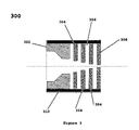
- FIG. 3 is a cross section of the light beam shaping, collimator, and beam dump module 203 of FIG. 2 for the apparatus of FIG. 1 ;
- FIG. 4 is a layout of the patient and operator optics 107 and 108 of FIG. 2 for the apparatus of FIG. 1 ;
- FIG. 5 illustrates how the light beam responds to the movement of the eye front surface in response to the ocular pulse
- FIG. 6 is a plot of the light beam optical magnification vs. the incident angle of the input laser beam illustrating the variation of magnification
- FIG. 7 is a plot of the displacement of the light beam vs. the displacement of the eye surface in response to the ocular pulse.
- FIG. 8 is a plot of the reflected light beam energy at the optical detector as a function of the light beam incident angle
- FIG. 9 is a plot of a simulated power spectrum illustrating the IOP as the zero frequency component with three higher frequency components.
- FIG. 1 is a block diagram of an embodiment of the ocular pulse analyzer.
- a solid state laser 101 produces a pulsed axially symmetric Gaussian beam of 670 nm frequency, and 1 milliwatt power which is injected along the incident-beam-line IO into the beam forming optics module 102 , which forms a small low divergence exit beam of up to 500 micro meters diameter and less than 1.0 milliradians angle which strikes the apex of the cornea O at a 65 to 75 degree angle with respect to the eye visual axis.
- the incident beam is reflected onto the reflected-beam-line OR at an angle of ⁇ 65 to ⁇ 75 degrees where it strikes a CCD camera array 105 which forms a pixelated image of the reflected beam spot width.
- the motion of the beam spot pixelated image on CCD camera array 105 is proportional to the movement of the eye front surface 104 as it responds to the ocular pulse.
- the eye orbit cup 109 is a compliant cup that forms an air tight seal on the eye orbit so that the equilibrium pressure at the eye front surface can be varied. Cup 109 also is the interface to the patient's face.
- the optics target module 107 projects an infinity image of an eye fixation target on which the patient focuses his vision thus minimizing random eye movement.
- Observation module 108 is used by the operator to align and observe the measurement. Both the fixation module 107 and the observation module 108 are aligned along the eye visual axis.
- the ocular pulse analyzer beam forming optics is contained in beam tube 103 , and the reflected beam components 106 are contained in beam tube 106 .
- the fixation module 107 , the observation module 108 and the eye orbit cup 109 are attached to an instrument stand 110 .
- the laser pulser is synchronized to the heart pulse by delayed triggers derived from the blood pulse sensors BPS, during each heart pulse up to 128 pixelated beam spot widths are digitized by the analog-to-digital-converter ADC and processed to provide measurements of the eye surface movement.
- the computer/display CPU/Disp system processes these data providing the operator with the IOP and other parameters. These data are stored in the patient data base DB.
- the CP/disp receives the pulse and timing data and sends control data to the DAC which then controls the laser pulser and the cup control module. By using the real time control module RTCntrl the operator controls the measurement and data processing parameters.
- FIG. 2 illustrates an embodiment of a compact left eye optic head 200 with mirror folded beam lines that allows high angle light reflection at the apex of the cornea.
- the incident laser beam from laser 101 is transformed by the beam forming module 102 which contains a 2.5 ⁇ inverted Keplerian telescope that expands and collimates the beam.
- the beam expander comprises a diffraction limited entrance lens 201 such as an infinity corrected, 5 ⁇ microscope objective of 36 mm focal length and numerical aperture 0.1, which forms a beam waist of about 14 micrometers diameter, followed by an exit lens 202 such as a 90 mm focal length doublet located one focal length from plane 201 a which forms a well collimated exit beam with at least a 10 mm diameter and a total divergence of less than 0.5 mrad at the entrance of beam shaping, collimator and dump module 203 which attenuates and collimates the beam using apertures of decreasing diameter.
- a diffraction limited entrance lens 201 such as an infinity corrected, 5 ⁇ microscope objective of 36 mm focal length and numerical aperture 0.1, which forms a beam waist of about 14 micrometers diameter
- an exit lens 202 such as a 90 mm focal length doublet located one focal length from plane 201 a which forms a well collimated exit beam with at least a 10 mm diameter and a total divergence of less than
- the beam has a diameter no larger than 500 micrometers, a divergence of less than 1.0 mrad, and a power of 1 microwatt at turning mirror 204 , which deflects the incident beam so that it strikes the apex of the cornea at an incident angle of from 65 to 75 degrees to the visual axis of the eye where it is reflected onto turning mirror 205 , which reflects the beam onto the normal to CCD camera array 105 , the beam then passes through the quadrature error detectors 206 which detect out of range reflected beam pulses, finally impinging onto CCD camera array 105 which forms a pixelated image of the reflected beam spot.
- the beam forming module 102 is mounted in beam tube 207 , the reflected beam components 206 and 105 in beam tube 208 and the compact optic head 200 in instrument case 209 , which also mounts the orbit cup 109 and mounts the fixation module 107 and the observation module 108 .
- instrument case 209 may be mounted on a standard slit lamp bench or other ophthalmic examination stand.
- FIG. 3 illustrates an embodiment of a beam shaping, collimator and beam dump 203 of FIG. 2 for the apparatus of FIG. 1 .
- the expanded laser beam enters beam dump 302 where the laser beam diameter is reduced by striking the walls which may be made of graphite, the beam passes through four alternating radial light traps 306 and four apertures 304 further reducing the beam diameter and divergence, light traps 306 collect large angle light rays, and scattered rays from wall scattering by multiple reflections in the radial traps further reducing stray light after passing through a beam defining exit aperture 308 the beam power may be reduced by a factor greater than 1000 may have a reduction of beam divergence of less than 1 milliradian and a diameter of less than 500 micrometers.
- the apertures may be produced by laser or other machining means and may be coated with an optically absorbent coating by sputtering or other means.
- the internal parts may be assembled with spacers into a stack that is self aligning.
- FIG. 4 illustrates the eye fixation module 107 and operator module 108 pertaining to FIG. 1 and compact optic head 200 of FIG. 2 .
- An incandescent light source 402 which is aligned on the extension of the eye visual axis, illuminates a grounded glass 404 , which then illuminates an optical fixation target 406 .
- Light from target 406 passes through beam splitter 408 , onto lens 410 which forms an image of the fixation target at infinity, which the patient fixes his eye on minimizing random eye motion.
- Light from eye surface 412 is reflected 90 degrees by beam splitter 408 , onto lens 414 , which forms an image of eye surface 412 on CCD camera array 416 , which provides the operator with a video observation of the measurement.
- FIG. 5 shows a geometric model of how the reflective head functions.
- the optic head is aligned to the eye surface at the time of the systolic ocular pulse point when eye surface 104 has moved to its maximum outward extent 104 .
- the optics projects the apertured spot image onto the corneal apex and reflects it onto the CCD array 105 which collects the reflected beam data point.
- the ocular pulse amplitude reduces the eye surface 104 moves inward.
- the projection of the incident beam is not changed, but the angle of incidence to the perturbed surface is changed (Snell's law applies).
- the reflected light centroid is shifted on the CCD camera array 105 , and the relative position of the beam on the detector increases.
- the eye front surface 104 moves radially inward along the eye visual axis VA, moving to the second eye surface 104 position 104 P 2 .
- To measure this movement we place a high brightness light source at the point (X0, Y0) aligned so the center of the output beam represented by a single ray intersects the initial eye surface 104 P 1 at (0,0) the corneal apex.
- the angle AO between the input ray and the eye crown visual axis is the angle of incidence of the input beam.
- the laws of reflection apply and the incident light ray is reflected along line (0,0)-( ⁇ X0,Y0) where it strikes the detector at the pixel located at point ( ⁇ X0,Y0) where the beam intensity profile is collected and the profile center of gravity calculated.
- the eye surface 104 moves towards the eye center along the eye visual axis until it reaches the second eye surface position 104 where the incident beam intersects the surface at the point (XN,YN) and is reflected to the array detector at point (XS,YS) along a new normal and a different angle of incidence and another data point is collected.
- the distance between the two reflected beam detector profiles is related to the displacement of the two eye surface locations.
- FIGS. 6 through 8 show the dependence of magnification on the angle of incidence, the pixelated signal displacement as a function of the eye surface motion and the fraction of beam reflected power as a function of angle of incidence.
- FIG. 6 shows the dependence of the light sensor magnification on the angle of incidence AO. Facial obstructions may limit the maximum angle of incidence to about 75 degrees with a useful range of about 65 to 75 degrees with a magnification range of about 30 to 50 times.
- FIG. 7 is a plot of a model of the pixelated beam spot image displacement versus the eye surface movement for a 12.5 mm radius spheroidal eyeball with an 8.5 mm corneal radius and a magnification of 50 times.
- FIG. 8 shows the optical beam energy reflected from the corneal apex vs the incident angle AO at an eyeball index of refraction of 1.356. The model results show that a coherent beam reflects more beam energy than an incoherent beam.
- FIG. 9 is a plot of a power spectrum from a simulated ocular pulse amplitude wave train showing the zero frequency power intensity plus three higher frequency components.
- the zero frequency power is the value of the mean energy in the IOP.
- This power spectrum is an example of the output obtained by using a commercial DSP program as may be understood by those possessing an ordinary skill in the pertinent arts
Landscapes
- Life Sciences & Earth Sciences (AREA)
- Health & Medical Sciences (AREA)
- Medical Informatics (AREA)
- Biophysics (AREA)
- Ophthalmology & Optometry (AREA)
- Engineering & Computer Science (AREA)
- Biomedical Technology (AREA)
- Heart & Thoracic Surgery (AREA)
- Physics & Mathematics (AREA)
- Molecular Biology (AREA)
- Surgery (AREA)
- Animal Behavior & Ethology (AREA)
- General Health & Medical Sciences (AREA)
- Public Health (AREA)
- Veterinary Medicine (AREA)
- Measuring Pulse, Heart Rate, Blood Pressure Or Blood Flow (AREA)
Abstract
Description
- This application is related to U.S. Provisional Patent Application Ser. No. 60/920,209 filed on Mar. 26, 2007, the entire disclosure of which is incorporated by reference as if set forth in its entirety herein.
- The present invention relates generally to ophthalmic clinical screening for the detection of eye and cerebrovascular disease by means of non-contact measurement of the ocular pulse amplitude of a subject's eyes.
- Determination of the intraocular pressure (IOP) is a component of the standard complete eye examination, a necessary test in the diagnosis and management of glaucoma and an indicator of underlying cerebrovascular diseases. A direct measure of the IOP requires surgically opening the eye and placing a device within it. This is not clinically useful on a large scale. Clinically, indirect methods are required to determine the IOP. The instruments used for this determination are called tonometers. Tonometers evaluate the IOP by seeing how much force it takes to distort the eye and inferring what intraocular pressure is required to resist the applied force, and declaring that to be the IOP.
- The force is applied to the eye by a plunger, an illuminated prism, a blast of air, a pneumatic pressure probe or piezoelectric crystals. All of these methods suffer from multiple problems. First, distorting the shape of the eye changes the pressure in the eye, reducing the accuracy of the test. Second, all of these instruments have a large mechanical component, introducing friction into the measurement. The damping effect of friction decreases the sensitivity of the test. Third, the force required for a tonometer to indent or flatten the eye surface in measuring the IOP is large compared to the energy contained within the ocular pulse wave. Therefore, the information carried in the ocular pulse wave and created in the eye following each heartbeat remains hidden. Fourth, the lack of ability to produce detailed ocular pulse wave measurements eliminates the opportunity to test both eyes concurrently and compare this data between the eyes. Fifth, applying force to the eye subjects the cornea to trauma.
- Our invention relates generally to ophthalmic clinical screening for the detection of eye and cerebrovascular disease by a non-contact measurement of the ocular pulse amplitude waveform
- The invention, an ocular pulse analyzer, probes the eye with a light beam and evaluates the eye's expansile response to an ocular pulse by analyzing movement of the reflected light beam. Valuable information about the ocular pulse is recorded in real time. The eye is not touched. The eye is not distorted. There is no friction interfering with the data and there is no trauma to the eye. The time of onset of the ocular pulse after the heart beat is easily measured. The amplitude of the ocular pulse, the duration of the ocular pulse and the shape of the ocular pulse is recorded to be compared with normal for each parameter. Since both eyes are tested concurrently, they are compared with each other.
- An embodiment of the ocular pulse analyzer consists of a pulsed laser diode followed by a laser beam expander with an internal spatial filter and a laser beam shaper which forms a low divergence small spot incident beam at the power required to safely strike the eye surface at a large incident angle on the apex of the cornea. The reflected beam emerges at an equal and opposite incident angle striking, the analyzer CCD camera array forming a pixelated image of the beam spot. During a single ocular pulse up to 128 points are obtained by calculating the center of gravity of each reflected beam spot profile. The distance of each data point from the CCD systolic reference point is proportional to the distance the eye front surface has moved. The collection of these points defines the ocular pulse amplitude waveform for each heart pulse. Sensors are used to generate triggers that pulse the laser and synchronize the analyzer control and data acquisition. Fast Fourier transforms (FFT) are used to analyze the data producing both the ocular pulse waveform and its power spectrum. The zero frequency amplitude of the power spectrum is a measure of the energy in the mean intraocular pressure (IOP) Non-zero frequency amplitudes measure energy that may be related to pressure changes during the ocular pulse and may be indicators of eye disease. Left-right eye data comparison may allow rapid detection of eye and cerebrovascular disease. Two of these optical analyzers may be mounted so that both of the subject's eyes can be examined simultaneously.
- Understanding of the present invention will be facilitated by consideration of the following detailed description of an embodiment of the present invention taken in conjunction with the accompanying drawings, in which like numerals refer to like parts and in which:
-
FIG. 1 illustrates a functional block diagram of the device according to an aspect of the present invention; and -
FIG. 2 illustrates a diagram of a folded optical system for the left eye for measuring the movement of the eye front surface during the ocular pulse for the apparatus ofFIG. 1 ; and -
FIG. 3 is a cross section of the light beam shaping, collimator, andbeam dump module 203 ofFIG. 2 for the apparatus ofFIG. 1 ; and -
FIG. 4 is a layout of the patient andoperator optics FIG. 2 for the apparatus ofFIG. 1 ; and -
FIG. 5 illustrates how the light beam responds to the movement of the eye front surface in response to the ocular pulse; and -
FIG. 6 is a plot of the light beam optical magnification vs. the incident angle of the input laser beam illustrating the variation of magnification; and -
FIG. 7 is a plot of the displacement of the light beam vs. the displacement of the eye surface in response to the ocular pulse; and -
FIG. 8 is a plot of the reflected light beam energy at the optical detector as a function of the light beam incident angle; and -
FIG. 9 is a plot of a simulated power spectrum illustrating the IOP as the zero frequency component with three higher frequency components. - It is to be understood that the figures and descriptions of the present invention have been simplified to illustrate elements that are relevant for a clear understanding of the present invention, while eliminating, for the purpose of clarity, many other elements found in typical optical systems and methods of manufacturing the same. Those of ordinary skill in the art will recognize that other elements and/or steps are desirable and/or required in implementing the present invention. However, because such elements and steps are well known in the art, and because they do not facilitate a better understanding of the present invention, a discussion of such elements and steps is not provided herein. The disclosure herein is directed to all such variations and modifications to such elements and methods known to those skilled in the art.
-
FIG. 1 is a block diagram of an embodiment of the ocular pulse analyzer. Asolid state laser 101 produces a pulsed axially symmetric Gaussian beam of 670 nm frequency, and 1 milliwatt power which is injected along the incident-beam-line IO into the beam formingoptics module 102, which forms a small low divergence exit beam of up to 500 micro meters diameter and less than 1.0 milliradians angle which strikes the apex of the cornea O at a 65 to 75 degree angle with respect to the eye visual axis. The incident beam is reflected onto the reflected-beam-line OR at an angle of −65 to −75 degrees where it strikes aCCD camera array 105 which forms a pixelated image of the reflected beam spot width. The motion of the beam spot pixelated image onCCD camera array 105 is proportional to the movement of theeye front surface 104 as it responds to the ocular pulse. Theeye orbit cup 109 is a compliant cup that forms an air tight seal on the eye orbit so that the equilibrium pressure at the eye front surface can be varied.Cup 109 also is the interface to the patient's face. Theoptics target module 107 projects an infinity image of an eye fixation target on which the patient focuses his vision thus minimizing random eye movement.Observation module 108 is used by the operator to align and observe the measurement. Both thefixation module 107 and theobservation module 108 are aligned along the eye visual axis. The ocular pulse analyzer beam forming optics is contained inbeam tube 103, and the reflectedbeam components 106 are contained inbeam tube 106. Thefixation module 107, theobservation module 108 and theeye orbit cup 109 are attached to aninstrument stand 110. - The laser pulser is synchronized to the heart pulse by delayed triggers derived from the blood pulse sensors BPS, during each heart pulse up to 128 pixelated beam spot widths are digitized by the analog-to-digital-converter ADC and processed to provide measurements of the eye surface movement. The computer/display CPU/Disp system processes these data providing the operator with the IOP and other parameters. These data are stored in the patient data base DB. The CP/disp receives the pulse and timing data and sends control data to the DAC which then controls the laser pulser and the cup control module. By using the real time control module RTCntrl the operator controls the measurement and data processing parameters.
-
FIG. 2 illustrates an embodiment of a compact left eyeoptic head 200 with mirror folded beam lines that allows high angle light reflection at the apex of the cornea. The incident laser beam fromlaser 101 is transformed by thebeam forming module 102 which contains a 2.5× inverted Keplerian telescope that expands and collimates the beam. The beam expander comprises a diffractionlimited entrance lens 201 such as an infinity corrected, 5× microscope objective of 36 mm focal length and numerical aperture 0.1, which forms a beam waist of about 14 micrometers diameter, followed by anexit lens 202 such as a 90 mm focal length doublet located one focal length fromplane 201 a which forms a well collimated exit beam with at least a 10 mm diameter and a total divergence of less than 0.5 mrad at the entrance of beam shaping, collimator anddump module 203 which attenuates and collimates the beam using apertures of decreasing diameter. At the beam shaping anddump module 203 exit, the beam has a diameter no larger than 500 micrometers, a divergence of less than 1.0 mrad, and a power of 1 microwatt at turningmirror 204, which deflects the incident beam so that it strikes the apex of the cornea at an incident angle of from 65 to 75 degrees to the visual axis of the eye where it is reflected onto turningmirror 205, which reflects the beam onto the normal toCCD camera array 105, the beam then passes through thequadrature error detectors 206 which detect out of range reflected beam pulses, finally impinging ontoCCD camera array 105 which forms a pixelated image of the reflected beam spot. To provide noise and stray light shielding; thebeam forming module 102 is mounted inbeam tube 207, the reflectedbeam components beam tube 208 and thecompact optic head 200 ininstrument case 209, which also mounts theorbit cup 109 and mounts thefixation module 107 and theobservation module 108. As may be understood by those possessing an ordinary skill in the pertinentarts instrument case 209 may be mounted on a standard slit lamp bench or other ophthalmic examination stand. -
FIG. 3 illustrates an embodiment of a beam shaping, collimator andbeam dump 203 ofFIG. 2 for the apparatus ofFIG. 1 . The expanded laser beam entersbeam dump 302 where the laser beam diameter is reduced by striking the walls which may be made of graphite, the beam passes through four alternating radiallight traps 306 and fourapertures 304 further reducing the beam diameter and divergence,light traps 306 collect large angle light rays, and scattered rays from wall scattering by multiple reflections in the radial traps further reducing stray light after passing through a beam definingexit aperture 308 the beam power may be reduced by a factor greater than 1000 may have a reduction of beam divergence of less than 1 milliradian and a diameter of less than 500 micrometers. As may be understood by those possessing an ordinary skill in the pertinent arts the apertures may be produced by laser or other machining means and may be coated with an optically absorbent coating by sputtering or other means. The internal parts may be assembled with spacers into a stack that is self aligning. -
FIG. 4 illustrates theeye fixation module 107 andoperator module 108 pertaining toFIG. 1 and compactoptic head 200 ofFIG. 2 . An incandescentlight source 402 which is aligned on the extension of the eye visual axis, illuminates a groundedglass 404, which then illuminates anoptical fixation target 406. Light fromtarget 406 passes throughbeam splitter 408, ontolens 410 which forms an image of the fixation target at infinity, which the patient fixes his eye on minimizing random eye motion. Light fromeye surface 412 is reflected 90 degrees bybeam splitter 408, ontolens 414, which forms an image ofeye surface 412 onCCD camera array 416, which provides the operator with a video observation of the measurement. -
FIG. 5 shows a geometric model of how the reflective head functions. Initially the optic head is aligned to the eye surface at the time of the systolic ocular pulse point wheneye surface 104 has moved to its maximumoutward extent 104. At this time the optics projects the apertured spot image onto the corneal apex and reflects it onto theCCD array 105 which collects the reflected beam data point. As the ocular pulse amplitude reduces theeye surface 104 moves inward. The projection of the incident beam is not changed, but the angle of incidence to the perturbed surface is changed (Snell's law applies). The reflected light centroid is shifted on theCCD camera array 105, and the relative position of the beam on the detector increases. A similar situation occurs when the ocular pulse pressure is raised, except that the reflected light shift moves in the opposite direction. The curvature of the corneal apex and the change in the location of the eye surface normal with respect to the incident beam provide a 50 times magnification of the eye surface movement at an incidence angle of 75 degrees with an equal reflected beam drift of 50 mm. The measurement of the eye surface motion can be explained from the single ray trace deflection diagram given inFIG. 5 which shows two positions of theeye surface 104 during a single ocular pulse. The origin of the diagram is at the point (0,0) at a time ts the time of the systolic peak of the ocular pulse. As the pulse amplitude decreases the eyefront surface 104 moves radially inward along the eye visual axis VA, moving to thesecond eye surface 104 position 104P2. To measure this movement we place a high brightness light source at the point (X0, Y0) aligned so the center of the output beam represented by a single ray intersects the initial eye surface 104P1 at (0,0) the corneal apex. The angle AO between the input ray and the eye crown visual axis is the angle of incidence of the input beam. Physically the laws of reflection apply and the incident light ray is reflected along line (0,0)-(−X0,Y0) where it strikes the detector at the pixel located at point (−X0,Y0) where the beam intensity profile is collected and the profile center of gravity calculated. At time (ts+δt) theeye surface 104 moves towards the eye center along the eye visual axis until it reaches the secondeye surface position 104 where the incident beam intersects the surface at the point (XN,YN) and is reflected to the array detector at point (XS,YS) along a new normal and a different angle of incidence and another data point is collected. The distance between the two reflected beam detector profiles is related to the displacement of the two eye surface locations. -
FIGS. 6 through 8 show the dependence of magnification on the angle of incidence, the pixelated signal displacement as a function of the eye surface motion and the fraction of beam reflected power as a function of angle of incidence.FIG. 6 shows the dependence of the light sensor magnification on the angle of incidence AO. Facial obstructions may limit the maximum angle of incidence to about 75 degrees with a useful range of about 65 to 75 degrees with a magnification range of about 30 to 50 times.FIG. 7 is a plot of a model of the pixelated beam spot image displacement versus the eye surface movement for a 12.5 mm radius spheroidal eyeball with an 8.5 mm corneal radius and a magnification of 50 times.FIG. 8 shows the optical beam energy reflected from the corneal apex vs the incident angle AO at an eyeball index of refraction of 1.356. The model results show that a coherent beam reflects more beam energy than an incoherent beam. -
FIG. 9 is a plot of a power spectrum from a simulated ocular pulse amplitude wave train showing the zero frequency power intensity plus three higher frequency components. The zero frequency power is the value of the mean energy in the IOP. This power spectrum is an example of the output obtained by using a commercial DSP program as may be understood by those possessing an ordinary skill in the pertinent arts - Those of ordinary skill in the art will recognize that many modifications and variations of the present invention may be implemented without departing from the spirit or scope of the invention. Thus, it is intended that the present invention cover the modification and variations of this invention provided they come within the scope of the appended claims and their equivalents.
Claims (2)
Priority Applications (1)
| Application Number | Priority Date | Filing Date | Title |
|---|---|---|---|
| US12/077,778 US8740795B2 (en) | 2007-03-26 | 2008-03-21 | Reflective non-contact ocular pulse analyzer for clinical diagnosis of eye and cerebrovascular disease |
Applications Claiming Priority (2)
| Application Number | Priority Date | Filing Date | Title |
|---|---|---|---|
| US92020907P | 2007-03-26 | 2007-03-26 | |
| US12/077,778 US8740795B2 (en) | 2007-03-26 | 2008-03-21 | Reflective non-contact ocular pulse analyzer for clinical diagnosis of eye and cerebrovascular disease |
Publications (2)
| Publication Number | Publication Date |
|---|---|
| US20080242965A1 true US20080242965A1 (en) | 2008-10-02 |
| US8740795B2 US8740795B2 (en) | 2014-06-03 |
Family
ID=39795575
Family Applications (1)
| Application Number | Title | Priority Date | Filing Date |
|---|---|---|---|
| US12/077,778 Expired - Fee Related US8740795B2 (en) | 2007-03-26 | 2008-03-21 | Reflective non-contact ocular pulse analyzer for clinical diagnosis of eye and cerebrovascular disease |
Country Status (1)
| Country | Link |
|---|---|
| US (1) | US8740795B2 (en) |
Cited By (10)
| Publication number | Priority date | Publication date | Assignee | Title |
|---|---|---|---|---|
| US20150077820A1 (en) * | 2013-09-17 | 2015-03-19 | Alps Electric Co., Ltd. | Image projection apparatus |
| WO2016009334A1 (en) * | 2014-07-17 | 2016-01-21 | Bitoun Pierre | Measurement of ocular parameters using vibrations induced in the eye |
| CN113951846A (en) * | 2021-12-17 | 2022-01-21 | 北京麦邦光电仪器有限公司 | Pulse wave signal processing method and device and readable storage medium |
| US11439303B2 (en) | 2014-03-04 | 2022-09-13 | Photono Oy | Method and arrangement for eye pressure measurements |
| US11529230B2 (en) | 2019-04-05 | 2022-12-20 | Amo Groningen B.V. | Systems and methods for correcting power of an intraocular lens using refractive index writing |
| US11564839B2 (en) | 2019-04-05 | 2023-01-31 | Amo Groningen B.V. | Systems and methods for vergence matching of an intraocular lens with refractive index writing |
| US11583389B2 (en) * | 2019-04-05 | 2023-02-21 | Amo Groningen B.V. | Systems and methods for correcting photic phenomenon from an intraocular lens and using refractive index writing |
| US11583388B2 (en) | 2019-04-05 | 2023-02-21 | Amo Groningen B.V. | Systems and methods for spectacle independence using refractive index writing with an intraocular lens |
| US11678975B2 (en) | 2019-04-05 | 2023-06-20 | Amo Groningen B.V. | Systems and methods for treating ocular disease with an intraocular lens and refractive index writing |
| US11944574B2 (en) | 2019-04-05 | 2024-04-02 | Amo Groningen B.V. | Systems and methods for multiple layer intraocular lens and using refractive index writing |
Families Citing this family (3)
| Publication number | Priority date | Publication date | Assignee | Title |
|---|---|---|---|---|
| EP3164056B1 (en) * | 2014-07-01 | 2021-12-01 | AMO Development, LLC | System and method for corneal topography with flat panel display |
| US9962077B2 (en) | 2014-07-01 | 2018-05-08 | Amo Wavefront Sciences, Llc | System and method for corneal topography with flat panel display |
| US11197604B2 (en) | 2018-10-05 | 2021-12-14 | Mark Schneider | Mobile phone cornea Placido disc image |
Citations (10)
| Publication number | Priority date | Publication date | Assignee | Title |
|---|---|---|---|---|
| US5101113A (en) * | 1989-05-16 | 1992-03-31 | Arizona Board Of Regents | Ensemble scattering particle sizing system with axial spatial resolution |
| US5148807A (en) * | 1990-08-28 | 1992-09-22 | Ohio State University | Non-contact tonometer |
| US5474066A (en) * | 1994-01-31 | 1995-12-12 | Leica Inc. | Non-contact tonometer |
| US5810005A (en) * | 1993-08-04 | 1998-09-22 | Dublin, Jr.; Wilbur L. | Apparatus and method for monitoring intraocular and blood pressure by non-contact contour measurement |
| US5954645A (en) * | 1998-04-03 | 1999-09-21 | Leica Microsystems Inc. | Applanation detection system for a non-contact tonometer |
| US6033075A (en) * | 1998-03-31 | 2000-03-07 | Nidek Co., Ltd. | Ophthalmic apparatus |
| US20020049373A1 (en) * | 2000-07-26 | 2002-04-25 | Nidek Co., Ltd | Non-contact type tonometer |
| US6673014B2 (en) * | 2001-10-05 | 2004-01-06 | Itonix, Inc. | Noninvasive methods and apparatuses for measuring the intraocular pressure of a mammal eye |
| US20040039298A1 (en) * | 1996-09-04 | 2004-02-26 | Abreu Marcio Marc | Noninvasive measurement of chemical substances |
| US20050030473A1 (en) * | 2003-06-12 | 2005-02-10 | Welch Allyn, Inc. | Apparatus and method for determining intraocular pressure and corneal thickness |
Family Cites Families (8)
| Publication number | Priority date | Publication date | Assignee | Title |
|---|---|---|---|---|
| US2519681A (en) | 1946-07-27 | 1950-08-22 | Mueller & Company V | Tonometer head |
| US3049001A (en) | 1959-06-18 | 1962-08-14 | Univ California | Tonometer |
| US3070087A (en) | 1959-09-29 | 1962-12-25 | Franklin Institute | Tonometer |
| US3181351A (en) | 1962-11-06 | 1965-05-04 | Honeywell Inc | Non-contacting tonometer |
| RU2103906C1 (en) * | 1992-12-21 | 1998-02-10 | Борис Михайлович Климашов | Non-contacting method and device for measuring intraocular pressure |
| GB2295460B (en) | 1994-11-26 | 1998-04-29 | O B F Labs | Improvements in and relating to a pneumatic pressure probe |
| US6776756B2 (en) | 2001-05-16 | 2004-08-17 | Marco Ophthalmic, Inc. | Applanation tonometer |
| EP1489958B1 (en) | 2002-03-28 | 2015-07-15 | i SONIC MEDICAL | A non-contacting tonometer |
-
2008
- 2008-03-21 US US12/077,778 patent/US8740795B2/en not_active Expired - Fee Related
Patent Citations (10)
| Publication number | Priority date | Publication date | Assignee | Title |
|---|---|---|---|---|
| US5101113A (en) * | 1989-05-16 | 1992-03-31 | Arizona Board Of Regents | Ensemble scattering particle sizing system with axial spatial resolution |
| US5148807A (en) * | 1990-08-28 | 1992-09-22 | Ohio State University | Non-contact tonometer |
| US5810005A (en) * | 1993-08-04 | 1998-09-22 | Dublin, Jr.; Wilbur L. | Apparatus and method for monitoring intraocular and blood pressure by non-contact contour measurement |
| US5474066A (en) * | 1994-01-31 | 1995-12-12 | Leica Inc. | Non-contact tonometer |
| US20040039298A1 (en) * | 1996-09-04 | 2004-02-26 | Abreu Marcio Marc | Noninvasive measurement of chemical substances |
| US6033075A (en) * | 1998-03-31 | 2000-03-07 | Nidek Co., Ltd. | Ophthalmic apparatus |
| US5954645A (en) * | 1998-04-03 | 1999-09-21 | Leica Microsystems Inc. | Applanation detection system for a non-contact tonometer |
| US20020049373A1 (en) * | 2000-07-26 | 2002-04-25 | Nidek Co., Ltd | Non-contact type tonometer |
| US6673014B2 (en) * | 2001-10-05 | 2004-01-06 | Itonix, Inc. | Noninvasive methods and apparatuses for measuring the intraocular pressure of a mammal eye |
| US20050030473A1 (en) * | 2003-06-12 | 2005-02-10 | Welch Allyn, Inc. | Apparatus and method for determining intraocular pressure and corneal thickness |
Cited By (15)
| Publication number | Priority date | Publication date | Assignee | Title |
|---|---|---|---|---|
| US20150077820A1 (en) * | 2013-09-17 | 2015-03-19 | Alps Electric Co., Ltd. | Image projection apparatus |
| US11439303B2 (en) | 2014-03-04 | 2022-09-13 | Photono Oy | Method and arrangement for eye pressure measurements |
| US11659994B2 (en) | 2014-03-04 | 2023-05-30 | Photono Oy | Method and arrangement for eye pressure measurements |
| US11471050B2 (en) | 2014-03-04 | 2022-10-18 | Photono Oy | Method and arrangement for eye pressure measurements |
| US11006828B2 (en) | 2014-07-17 | 2021-05-18 | 1 Sonic Medical Corporation, S.A.S. | Measurement of ocular parameters using vibrations induced in the eye |
| CN107072529A (en) * | 2014-07-17 | 2017-08-18 | 爱音医疗股份有限公司 | Eye parameters are measured using the vibration sensed in eye |
| WO2016009334A1 (en) * | 2014-07-17 | 2016-01-21 | Bitoun Pierre | Measurement of ocular parameters using vibrations induced in the eye |
| US11529230B2 (en) | 2019-04-05 | 2022-12-20 | Amo Groningen B.V. | Systems and methods for correcting power of an intraocular lens using refractive index writing |
| US11564839B2 (en) | 2019-04-05 | 2023-01-31 | Amo Groningen B.V. | Systems and methods for vergence matching of an intraocular lens with refractive index writing |
| US11583389B2 (en) * | 2019-04-05 | 2023-02-21 | Amo Groningen B.V. | Systems and methods for correcting photic phenomenon from an intraocular lens and using refractive index writing |
| US11583388B2 (en) | 2019-04-05 | 2023-02-21 | Amo Groningen B.V. | Systems and methods for spectacle independence using refractive index writing with an intraocular lens |
| US11678975B2 (en) | 2019-04-05 | 2023-06-20 | Amo Groningen B.V. | Systems and methods for treating ocular disease with an intraocular lens and refractive index writing |
| US11931296B2 (en) | 2019-04-05 | 2024-03-19 | Amo Groningen B.V. | Systems and methods for vergence matching of an intraocular lens with refractive index writing |
| US11944574B2 (en) | 2019-04-05 | 2024-04-02 | Amo Groningen B.V. | Systems and methods for multiple layer intraocular lens and using refractive index writing |
| CN113951846A (en) * | 2021-12-17 | 2022-01-21 | 北京麦邦光电仪器有限公司 | Pulse wave signal processing method and device and readable storage medium |
Also Published As
| Publication number | Publication date |
|---|---|
| US8740795B2 (en) | 2014-06-03 |
Similar Documents
| Publication | Publication Date | Title |
|---|---|---|
| US8740795B2 (en) | Reflective non-contact ocular pulse analyzer for clinical diagnosis of eye and cerebrovascular disease | |
| US7084986B2 (en) | System for measuring the optical image quality of an eye in a contactless manner | |
| EP1605815B1 (en) | Moiré- aberrometer | |
| US7659971B2 (en) | Lensometers and wavefront sensors and methods of measuring aberration | |
| US9364148B2 (en) | Method and apparatus for measuring the deformation characteristics of an object | |
| EP1379158B1 (en) | Method for determining clinical refraction of eye from objective source | |
| US7677728B2 (en) | Ophthalmologic measuring apparatus | |
| EP3001945B1 (en) | Lensometers and wavefront sensors and methods of measuring aberration | |
| US7241012B2 (en) | Ophthalmologic apparatus | |
| US20030028115A1 (en) | System and method for reconstruction of aberrated wavefronts | |
| WO1994023641A1 (en) | Retinal eye disease diagnostic system | |
| EP0337745A1 (en) | Ophthalmological diagnosis method and apparatus | |
| CN101259009B (en) | Cornea topographic map measurer | |
| CN109645954B (en) | Multi-beam optical coherence elasticity measurement system and method based on microlens array | |
| CN105962886A (en) | Ophthalmic apparatus and control method for the same | |
| CN109620130B (en) | Common-light-path multi-beam optical coherence elasticity measurement system and measurement method | |
| EP0386927B1 (en) | Ophthalmological diagnosis apparatus | |
| US4950070A (en) | Ophthalmological diagnosis method and apparatus | |
| US6454722B1 (en) | Doppler velocimeter for blood flow | |
| US20230079050A1 (en) | Ophthalmic device | |
| CN109620131A (en) | Optical path microlens array multiple beam optical coherence elasticity measurement system and method altogether | |
| CN113229777B (en) | Visual quality analyzer | |
| JP2020195883A (en) | Ophthalmologic inspection device | |
| CN209733949U (en) | optical coherence tomography system for measuring eyeball pulsation | |
| CN213309629U (en) | Eyeball imaging device and eyeball blood flow velocity measuring device |
Legal Events
| Date | Code | Title | Description |
|---|---|---|---|
| AS | Assignment |
Owner name: NUSEON LLC, CALIFORNIA Free format text: ASSIGNMENT OF ASSIGNORS INTEREST;ASSIGNORS:NORRIS, JOHN L.;ALLISON, ROBERT W., JR.;REEL/FRAME:028669/0471 Effective date: 20120614 |
|
| STCF | Information on status: patent grant |
Free format text: PATENTED CASE |
|
| FEPP | Fee payment procedure |
Free format text: MAINTENANCE FEE REMINDER MAILED (ORIGINAL EVENT CODE: REM.) |
|
| FEPP | Fee payment procedure |
Free format text: SURCHARGE FOR LATE PAYMENT, SMALL ENTITY (ORIGINAL EVENT CODE: M2554) |
|
| MAFP | Maintenance fee payment |
Free format text: PAYMENT OF MAINTENANCE FEE, 4TH YR, SMALL ENTITY (ORIGINAL EVENT CODE: M2551) Year of fee payment: 4 |
|
| FEPP | Fee payment procedure |
Free format text: MAINTENANCE FEE REMINDER MAILED (ORIGINAL EVENT CODE: REM.); ENTITY STATUS OF PATENT OWNER: SMALL ENTITY |
|
| LAPS | Lapse for failure to pay maintenance fees |
Free format text: PATENT EXPIRED FOR FAILURE TO PAY MAINTENANCE FEES (ORIGINAL EVENT CODE: EXP.); ENTITY STATUS OF PATENT OWNER: SMALL ENTITY |
|
| STCH | Information on status: patent discontinuation |
Free format text: PATENT EXPIRED DUE TO NONPAYMENT OF MAINTENANCE FEES UNDER 37 CFR 1.362 |
|
| FP | Lapsed due to failure to pay maintenance fee |
Effective date: 20220603 |