US20080098510A1 - Pivoting and locking wall mounted support rail for elderly & disabled persons - Google Patents
Pivoting and locking wall mounted support rail for elderly & disabled persons Download PDFInfo
- Publication number
- US20080098510A1 US20080098510A1 US11/589,827 US58982706A US2008098510A1 US 20080098510 A1 US20080098510 A1 US 20080098510A1 US 58982706 A US58982706 A US 58982706A US 2008098510 A1 US2008098510 A1 US 2008098510A1
- Authority
- US
- United States
- Prior art keywords
- diameter
- pivot
- handrail
- wall
- vertical member
- Prior art date
- Legal status (The legal status is an assumption and is not a legal conclusion. Google has not performed a legal analysis and makes no representation as to the accuracy of the status listed.)
- Granted
Links
Images

Classifications
-
- A—HUMAN NECESSITIES
- A47—FURNITURE; DOMESTIC ARTICLES OR APPLIANCES; COFFEE MILLS; SPICE MILLS; SUCTION CLEANERS IN GENERAL
- A47K—SANITARY EQUIPMENT NOT OTHERWISE PROVIDED FOR; TOILET ACCESSORIES
- A47K17/00—Other equipment, e.g. separate apparatus for deodorising, disinfecting or cleaning devices without flushing for toilet bowls, seats or covers; Holders for toilet brushes
- A47K17/02—Body supports, other than seats, for closets, e.g. handles, back-rests, foot-rests; Accessories for closets, e.g. reading tables
- A47K17/022—Wall mounted grab bars or handles, with or without support on the floor
- A47K17/024—Wall mounted grab bars or handles, with or without support on the floor pivotally mounted on the wall
Definitions
- This invention relates to a pivoting and locking wall mounted support rail assembly which improves support to assist elderly and disabled persons while entering into, moving within, or exiting from a bathtub or shower area.
- Entering and moving safely within a typical bathtub area may be a difficult process for some elderly and disabled persons. Particularly, traversing the bath tub outer threshold can cause a loss of balance
- a bathtub requires several tasks that require balance, namely, entering bathtub and stepping over tub outer wall, maintaining stability while standing in the tub, working the shower controls, balancing while using the hand shower, lowering to a seated position on a bath board or shower seat, raising to a standing position from the bath board or shower seat, lowering to sit on the floor of the tub, and subsequently regain a standing position. This all occurs in an area that is wet, slippery, and typically without assistance, or well located hand rail support.
- Wall mounted grab bars typically force a user entering the tub to reach across to the grab bar on the far wall—This reaching can cause a loss of balance before the support is at hand.
- the user When in the bathtub, the user must twist to the side to keep the support at hand. This takes away the use of one or both hands to maintain balance while the hands are needed for tasks such as washing, adjusting water controls, etc
- Tub side mounted support rails are typically a little low in height to be of value, are not always secure, and can prevent the use of shower curtain or rigid shower doors
- Floor to ceiling poles mounted alongside the tub can assist with entry, and mobility to start a bath, however, they are not available when the shower curtain or doors are closed.
- Bath sitting boards and shower seats do not help while the user is standing, and are bulky, and cumbersome to remove for additional persons using the bathtub or shower who do not need these devices. Furthermore, they are not secured in their position, and as a result can move at the instant when secure support is required.
- None of the above prior art devices allow the user to lean forward on the support while adjusting the shower controls. None have the ability to easily move the hand rail support to where it is optimal, and move it again when it may be in the way for the next manoeuvre, or the next occupant. Further, many of the above devices have handrail support at only one height, which may not be optimal for all movement tasks.
- the present devices do not address full safety of the user of a bath or shower area.
- the present invention has a pivoting and locking rail that locks in numerous angular positions to provide optimal support for different activities in the bathtub—i.e. showering, adjusting controls, seating, entering, exiting,
- the pivoting and locking rail locks and unlocks easily—lift the pivot rail assembly to unlock it, hold it up to rotate it freely, and lower at any time to find the nearest agular locking position.
- the pivoting rail stores out of the way along the wall when not in use to permit full enjoyment of the bathtub by other users not needing such support.
- the complete system has three height levels of support to help with low tasks such as lowering down to sit on the floor of the tub, to mid level activities, such as transitional phase of standing up from a seating position, to high activities such as standing support.
- the angular locking feature is fully able to handle shower water on it and through it without consequence.
- the ambidextrous nature of the locking feature permits installation in both directions—with pivot rail vertical tube on the left or the right side
- the top pivot collar assembly has dual tapered bore feature that allows for uneven walls and slight angular installation errors.
- the guide sleeve inside the top pivot collar prevents wear marks on pivot tube of pivot rail assembly and dampens lateral sliding sounds.
- the system attaches to wall using known methods.
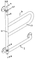
- FIG. 1 is a perspective view of one embodiment of the present invention as would be mounted on a wall, with the pivot rail assembly in the “stored along wall” angular position
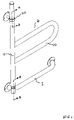
- FIG. 2 is a perspective view of one embodiment of the present invention as would be mounted on a wall, with the pivot rail assembly in the “90 degree pivoted outward” angular position
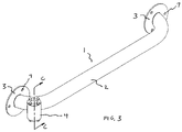
- FIG. 3 is a perspective view of the grab bar assembly
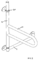
- FIG. 4 is a perspective view of the pivot rail assembly
- FIG. 5 is a perspective view of the pivot collar assembly
- FIG. 6 is a partial section view “A-A” of a portion of the pivot rail assembly as held within the pivot collar assembly
- FIG. 7 is a partial perspective view of the bottom of the pivot rail assembly
- FIG. 8 is a partial perspective view of the grab bar assembly
- FIG. 9 is a partial perspective/section view “C-C” of the grab bar assembly
- FIG. 10 is a partial perspective/section view “B-B” of the main assembly
- FIG. 1 illustrates one embodiment of the present invention showing the wall mounted pivoting support rail 6 , as a complete system, as it would be installed on a typical wall such as the long wall alongside a bathtub.
- the main assembly 6 comprises three major components, namely, the grab bar assembly 1 , the pivot rail assembly, 10 , and the pivot collar assembly 20 . These three major components are combined in place, secured on a wall surface to achieve the working main assembly.
- FIG. 1 shows the pivot rail assembly 10 , located in its rotational position for storing the pivot rail assembly 10 alongside the wall. This position is advantageous both for storing the pivot rail assembly 10 , out of the way, along the wall, as well as, for actual use of the pivot rail assembly 10 in this position, to benefit from the higher gripping levels of the pivot rail assembly 10 .
- FIG. 2 shows the pivot rail assembly 10 , in one of the available locked rotational positions whereby the pivot rail assembly 10 , is situated at approximately 90 degrees outward from the wall.
- the pivot rail assembly 10 as described in the preferred embodiment, is also able to pivot and lock at additional angular positions, including 45, 135 and 180 degrees to the wall. Additional in-between locking angular positions could be achieved by modification to the preferred embodiment by those skilled in the art. The mechanism for locking is described later in this text.
- FIG. 2 shows the main pivot tube 11 , of the pivot rail assembly 10 , supported above the left side of the grab bar assembly 1 .
- the ambidextrous design of the grab bar assembly 1 is such that it will permit the system to have the main pivot tube 11 , of the pivot rail assembly 10 , supported above the right side of the grab bar assembly 1 , by inverting the grab bar assembly 1 , as is described further on in this text.
- FIG. 3 shows the grab bar assembly 1 , which comprises two wall flanges 3 , fastened onto ends of cross member 2 , such that cross member 2 is held essentially parallel to a wall when installed.
- Wall flanges 3 have apertures 7 , through which fasteners (not shown) may be installed to secure the grab bar assembly 1 , to a wall.
- Toothed collar 4 is secured within a mating notch in the outer surface of cross member 2 by permanent means such as welding, adhesive, or fasteners. It is located such that its central vertical axis intersects with the central horizontal axes of the cross member 2 , and wall flange 3 .
- the elements of grab bar assembly 1 may be constructed of a strong corrosion resistant material such as high strength reinforced plastic, or more favourably, steel with a corrosion resistant finish, or an aluminum alloy, or most favourably, stainless steel, which is both strong, and corrosion resistant through it's entire depth, even in moving mating areas where a protective surface finish may wear off over time
- a strong corrosion resistant material such as high strength reinforced plastic, or more favourably, steel with a corrosion resistant finish, or an aluminum alloy, or most favourably, stainless steel, which is both strong, and corrosion resistant through it's entire depth, even in moving mating areas where a protective surface finish may wear off over time
- FIG. 4 shows the pivot rail assembly 10 , which comprises u-rail 12 which is permanently fastened onto pivot tube 11 by permanent means such as welding, adhesive or fasteners (not shown).
- the u-rail 12 provides strength due to it's closed loop design, however alternative embodiments such as a wider “D” shape, “B” shape or other profiles could be attached to the pivot tube 11 .
- the cross section of the u-rail could favourably be circular, oval, or oblong.
- a grooved collar 14 is installed coaxially into the bottom end of the pivot tube 11 , and secured by means such as welding, adhesive or fasteners (not shown).
- a limit bushing 15 is held in place coaxially to the grooved collar 14 central axis to the bottom end of the grooved collar 14 , by means of a screw 16 .
- the top end of the pivot tube 11 is sealed by means of the top cap 13 , which forms a liquid and vapour tight seal which is important in a bathtub and shower environment.
- Top cap 13 may be fabricated from a lightweight corrosion resistant material such as plastic.
- the elements of pivot rail assembly 10 may be constructed of a strong corrosion resistant material such as high strength reinforced plastic, or more favourably, steel with a corrosion resistant finish, or an aluminum alloy, or most favourably, stainless steel, which is both strong, and corrosion resistant, even in moving mating areas where a protective surface finish may wear off over time
- the final major assembly is the pivot collar assembly 20 .
- It comprises guide collar 23 , which is held by and attached to spacer 22 which is attached to wall plate 21 by permanent means such as welding or fasteners (not shown).
- Wall plate 21 has apertures 35 to permit screws to mount the pivot collar 20 to a wall.
- the pivot collar assembly is most favourably fabricated from a corrosion resistant material such as plastic or stainless steel.
- the inner bore 25 of guide collar 23 may be lined with a guide sleeve 24 to provide a more resilient surface to interface with the outside surface of the pivot tube 11 (not shown) of the pivot rail assembly 10 (not shown)
- FIG. 6 better illustrates the makeup of the pivot collar assembly 20 , by means of a section view “A-A”.
- Pivot tube 11 is held coaxially within the bore of guide collar 23 .
- Guide sleeve 24 may be held by a press fit, or within a groove 26 within the bore of guide collar 23 .
- the bore 25 surface is tapered somewhat outward in each direction from the middle of the bore 25 . This permits the pivot collar assembly 20 to accommodate some degree of angular error of installation, yet still maintain free motion of pivot tube 11 .
- FIG. 7 is a partial perspective view of the lower end of the pivot rail assembly 10 .
- the grooved collar 14 is shown situated in the lower end of pivot tube 11 , and secured with permanent means such as welding.
- the grooved collar has eight grooves 17 , which are spaced at equal angles about the bottom shoulder face 18 of the grooved collar 14 .
- a tapered stem 30 further protrudes from the bottom shoulder face 18 of the grooved collar 14 .
- the bottom surface 31 of the grooved collar 14 has a centrally located aperture (not shown) that is threaded to receive screw 16 .
- Limit bushing 15 has a minor diameter 32 , and tapered head 33 , that provides a shoulder 34 .
- the limit bushing 15 has an aperture (not shown) coaxially located through its entire length, to permit the clearance passage of the screw 16 .
- FIG. 8 shows a partial perspective view of the toothed collar on the grab bar assembly.
- FIG. 8 shows a plurality of teeth 8 , located on the top surface and the bottom surface of the toothed collar 4 arranged in a circular pattern in with equal angles between them. Having teeth 8 , located on the top and bottom surface of the toothed collar 4 , permits the grab bar assembly 1 to be used with the toothed collar 4 located on the left or the right side as most advantageous for the particular need.
- FIG. 9 shows a partial perspective section view “C-C” of the grab bar assembly 1 , with the section cut through the middle of the toothed collar 4 . From this view we can see the major bore 42 , the minor bore 9 , and resulting shoulders 41 A, and 41 B.
- FIG. 10 shows a partial perspective section view “B-B” of the locking interface between the bottom end of the pivot rail assembly 10 and the toothed collar 4 .
- the pivot rail assembly 10 is installed into the toothed collar 4 by first removing the screw 16 , of the limit bushing 15 , and setting the tapered stem 30 , of the grooved collar 14 , into the top major bore 42 of the toothed collar 4 .
- the minor diameter 32 of the limit bushing 15 is then inserted up through the bottom of the toothed collar 4 , and held in place against the bottom surface 31 of the tapered stem 30 of the grooved collar 14 by screw 16 engaging into threaded hole (not shown) of grooved collar 14 .
- the bottom end of the pivot rail assembly 10 is held coaxially within the toothed collar 4 , by the tapered stem 30 , centering itself within the major bore 42 of the toothed collar 4 , as well as the minor diameter 32 of the limit bushing 15 centering itself within the minor bore 9 of the toothed collar 4 .
- This arrangement allows the pivot rail assembly 10 to rotate coaxially about the toothed collar 4 , and move a limited amount of up and down axial motion within the toothed collar 4 .
- the teeth 8 of the toothed collar 4 will fit up inside of the grooves 17 of the grooved collar 14 .
- the user In order to unlock the pivot rail assembly 10 , to permit free rotation, the user must lift the pivot rail assembly 10 upward, thereby lifting the grooved collar 14 such that the teeth 8 of the toothed collar 4 are no longer in the grooves 17 of the grooved collar 14 . At this point the pivot rail assembly 10 may be freely rotated coaxially about the tooth collar 4 , and guided at the top by the pivot collar assembly 20 . The pivot rail assembly 10 , is prevented to lifting right out of the toothed collar 4 , by the shoulder 34 of the limit bushing 15 hitting against the shoulder 41 of the toothed collar 4 .
Landscapes
- Health & Medical Sciences (AREA)
- Public Health (AREA)
- Epidemiology (AREA)
- General Health & Medical Sciences (AREA)
- Bathtubs, Showers, And Their Attachments (AREA)
Abstract
A wall mounted pivoting and locking support rail assembly providing improved support to assist elderly and physically challenged persons with safely using a bathtub or shower area. The present invention mounts to the wall like a conventional grab bar, however, it adds an additional rail handle with the ability to pivot outward from the wall, and lock in one of several angular positions to extend support outward from the wall, and more to the centre of a shower or tub. This outward support is invaluable to assist with elderly and disabled persons to safely enter, use, and exit from the bathtub without dangerous reaching.
Description
- 1. Field of Invention
- This invention relates to a pivoting and locking wall mounted support rail assembly which improves support to assist elderly and disabled persons while entering into, moving within, or exiting from a bathtub or shower area.
- 2. Description of Prior Art
- Entering and moving safely within a typical bathtub area may be a difficult process for some elderly and disabled persons. Particularly, traversing the bath tub outer threshold can cause a loss of balance
- Use of a bathtub requires several tasks that require balance, namely, entering bathtub and stepping over tub outer wall, maintaining stability while standing in the tub, working the shower controls, balancing while using the hand shower, lowering to a seated position on a bath board or shower seat, raising to a standing position from the bath board or shower seat, lowering to sit on the floor of the tub, and subsequently regain a standing position. This all occurs in an area that is wet, slippery, and typically without assistance, or well located hand rail support.
- There are numerous prior art devices to assist with bathtub mobility and safety. These include; Wall mounted grab bars, tub side mounted support rails, floor to ceiling poles alongside the tub, bath sitting boards, shower seats, and transfer benches.
- There are numerous issues with the current devices
- Wall mounted grab bars typically force a user entering the tub to reach across to the grab bar on the far wall—This reaching can cause a loss of balance before the support is at hand. When in the bathtub, the user must twist to the side to keep the support at hand. This takes away the use of one or both hands to maintain balance while the hands are needed for tasks such as washing, adjusting water controls, etc
- Tub side mounted support rails are typically a little low in height to be of value, are not always secure, and can prevent the use of shower curtain or rigid shower doors
- Floor to ceiling poles mounted alongside the tub can assist with entry, and mobility to start a bath, however, they are not available when the shower curtain or doors are closed.
- Bath sitting boards and shower seats do not help while the user is standing, and are bulky, and cumbersome to remove for additional persons using the bathtub or shower who do not need these devices. Furthermore, they are not secured in their position, and as a result can move at the instant when secure support is required.
- None of the above prior art devices allow the user to lean forward on the support while adjusting the shower controls. None have the ability to easily move the hand rail support to where it is optimal, and move it again when it may be in the way for the next manoeuvre, or the next occupant. Further, many of the above devices have handrail support at only one height, which may not be optimal for all movement tasks.
- Clearly, the present devices do not address full safety of the user of a bath or shower area.
- Turning now to the present invention, it has a pivoting and locking rail that locks in numerous angular positions to provide optimal support for different activities in the bathtub—i.e. showering, adjusting controls, seating, entering, exiting,
- When the pivoting rail is swung out, it places support in the middle of the tub that permits both vertical and lateral loads. This permits users to lean on the rail for balance, and where appropriate, have more free use of their hands.
- The pivoting and locking rail locks and unlocks easily—lift the pivot rail assembly to unlock it, hold it up to rotate it freely, and lower at any time to find the nearest agular locking position.
- The pivoting rail stores out of the way along the wall when not in use to permit full enjoyment of the bathtub by other users not needing such support.
- The complete system has three height levels of support to help with low tasks such as lowering down to sit on the floor of the tub, to mid level activities, such as transitional phase of standing up from a seating position, to high activities such as standing support.
- The advantageous three point securement to the wall ensures that the rail will not get loose with time as might happen with two point securement
- The angular locking feature is fully able to handle shower water on it and through it without consequence.
- The ambidextrous nature of the locking feature permits installation in both directions—with pivot rail vertical tube on the left or the right side
- The top pivot collar assembly has dual tapered bore feature that allows for uneven walls and slight angular installation errors.
- The guide sleeve inside the top pivot collar prevents wear marks on pivot tube of pivot rail assembly and dampens lateral sliding sounds.
- The system attaches to wall using known methods.
- Other objects, features and versions of the present invention will become apparent from the following detailed description which, when interpreted with the listed drawings together disclose a preferred embodiment of the invention. It is to be understood that the drawings are intended for the purpose of illustration only, and are not intended as a definition of the limits of the invention.
-
FIG. 1 is a perspective view of one embodiment of the present invention as would be mounted on a wall, with the pivot rail assembly in the “stored along wall” angular position -
FIG. 2 is a perspective view of one embodiment of the present invention as would be mounted on a wall, with the pivot rail assembly in the “90 degree pivoted outward” angular position -
FIG. 3 is a perspective view of the grab bar assembly -
FIG. 4 is a perspective view of the pivot rail assembly -
FIG. 5 is a perspective view of the pivot collar assembly -
FIG. 6 is a partial section view “A-A” of a portion of the pivot rail assembly as held within the pivot collar assembly -
FIG. 7 is a partial perspective view of the bottom of the pivot rail assembly -
FIG. 8 is a partial perspective view of the grab bar assembly -
FIG. 9 is a partial perspective/section view “C-C” of the grab bar assembly -
FIG. 10 is a partial perspective/section view “B-B” of the main assembly - Referring now the figures,
FIG. 1 illustrates one embodiment of the present invention showing the wall mounted pivoting support rail 6, as a complete system, as it would be installed on a typical wall such as the long wall alongside a bathtub. - The main assembly 6, comprises three major components, namely, the
grab bar assembly 1, the pivot rail assembly, 10, and thepivot collar assembly 20. These three major components are combined in place, secured on a wall surface to achieve the working main assembly. -
FIG. 1 shows thepivot rail assembly 10, located in its rotational position for storing thepivot rail assembly 10 alongside the wall. This position is advantageous both for storing thepivot rail assembly 10, out of the way, along the wall, as well as, for actual use of thepivot rail assembly 10 in this position, to benefit from the higher gripping levels of thepivot rail assembly 10. - By comparison,
FIG. 2 shows thepivot rail assembly 10, in one of the available locked rotational positions whereby thepivot rail assembly 10, is situated at approximately 90 degrees outward from the wall. Thepivot rail assembly 10, as described in the preferred embodiment, is also able to pivot and lock at additional angular positions, including 45, 135 and 180 degrees to the wall. Additional in-between locking angular positions could be achieved by modification to the preferred embodiment by those skilled in the art. The mechanism for locking is described later in this text. - The illustrated embodiment in
FIG. 2 shows themain pivot tube 11, of thepivot rail assembly 10, supported above the left side of thegrab bar assembly 1. Alternatively, it should be noted that the ambidextrous design of thegrab bar assembly 1, is such that it will permit the system to have themain pivot tube 11, of thepivot rail assembly 10, supported above the right side of thegrab bar assembly 1, by inverting thegrab bar assembly 1, as is described further on in this text. - Turning now to better describe the major sub assemblies,
FIG. 3 shows thegrab bar assembly 1, which comprises twowall flanges 3, fastened onto ends ofcross member 2, such thatcross member 2 is held essentially parallel to a wall when installed.Wall flanges 3, have apertures 7, through which fasteners (not shown) may be installed to secure thegrab bar assembly 1, to a wall. Toothedcollar 4 is secured within a mating notch in the outer surface ofcross member 2 by permanent means such as welding, adhesive, or fasteners. It is located such that its central vertical axis intersects with the central horizontal axes of thecross member 2, andwall flange 3. - The elements of
grab bar assembly 1, may be constructed of a strong corrosion resistant material such as high strength reinforced plastic, or more favourably, steel with a corrosion resistant finish, or an aluminum alloy, or most favourably, stainless steel, which is both strong, and corrosion resistant through it's entire depth, even in moving mating areas where a protective surface finish may wear off over time - Continuing with major assemblies,
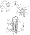
FIG. 4 shows thepivot rail assembly 10, which comprises u-rail 12 which is permanently fastened ontopivot tube 11 by permanent means such as welding, adhesive or fasteners (not shown). The u-rail 12 provides strength due to it's closed loop design, however alternative embodiments such as a wider “D” shape, “B” shape or other profiles could be attached to thepivot tube 11. The cross section of the u-rail could favourably be circular, oval, or oblong. Agrooved collar 14, is installed coaxially into the bottom end of thepivot tube 11, and secured by means such as welding, adhesive or fasteners (not shown). Alimit bushing 15 is held in place coaxially to thegrooved collar 14 central axis to the bottom end of thegrooved collar 14, by means of ascrew 16. The top end of thepivot tube 11, is sealed by means of thetop cap 13, which forms a liquid and vapour tight seal which is important in a bathtub and shower environment.Top cap 13 may be fabricated from a lightweight corrosion resistant material such as plastic. The elements ofpivot rail assembly 10, may be constructed of a strong corrosion resistant material such as high strength reinforced plastic, or more favourably, steel with a corrosion resistant finish, or an aluminum alloy, or most favourably, stainless steel, which is both strong, and corrosion resistant, even in moving mating areas where a protective surface finish may wear off over time - The final major assembly, shown in
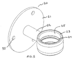
FIG. 5 , is thepivot collar assembly 20. It comprisesguide collar 23, which is held by and attached to spacer 22 which is attached towall plate 21 by permanent means such as welding or fasteners (not shown).Wall plate 21 hasapertures 35 to permit screws to mount thepivot collar 20 to a wall. The pivot collar assembly is most favourably fabricated from a corrosion resistant material such as plastic or stainless steel. In the case of stainless steel, theinner bore 25 ofguide collar 23 may be lined with aguide sleeve 24 to provide a more resilient surface to interface with the outside surface of the pivot tube 11 (not shown) of the pivot rail assembly 10 (not shown) -
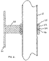
FIG. 6 better illustrates the makeup of thepivot collar assembly 20, by means of a section view “A-A”.Pivot tube 11 is held coaxially within the bore ofguide collar 23.Guide sleeve 24 may be held by a press fit, or within agroove 26 within the bore ofguide collar 23. There is advantageously a small amount of diametrical clearance between the outside diameter ofpivot tube 11, and the inside diameter ofguide sleeve 24 to permit to permit free rotational pivoting, as well as free up and down axial motion ofpivot tube 11 within thepivot collar assembly 20. Advantageously, thebore 25 surface is tapered somewhat outward in each direction from the middle of thebore 25. This permits thepivot collar assembly 20 to accommodate some degree of angular error of installation, yet still maintain free motion ofpivot tube 11. - Moving now to the method of pivot and locking,
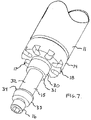
FIG. 7 is a partial perspective view of the lower end of thepivot rail assembly 10. Thegrooved collar 14 is shown situated in the lower end ofpivot tube 11, and secured with permanent means such as welding. The grooved collar has eight grooves 17, which are spaced at equal angles about thebottom shoulder face 18 of thegrooved collar 14. A taperedstem 30 further protrudes from thebottom shoulder face 18 of thegrooved collar 14. Thebottom surface 31 of thegrooved collar 14 has a centrally located aperture (not shown) that is threaded to receivescrew 16. - Limit
bushing 15 has aminor diameter 32, and taperedhead 33, that provides ashoulder 34. Thelimit bushing 15 has an aperture (not shown) coaxially located through its entire length, to permit the clearance passage of thescrew 16. - Moving now to
FIG. 8 , this shows a partial perspective view of the toothed collar on the grab bar assembly.FIG. 8 shows a plurality of teeth 8, located on the top surface and the bottom surface of thetoothed collar 4 arranged in a circular pattern in with equal angles between them. Having teeth 8, located on the top and bottom surface of thetoothed collar 4, permits thegrab bar assembly 1 to be used with thetoothed collar 4 located on the left or the right side as most advantageous for the particular need. -
FIG. 9 shows a partial perspective section view “C-C” of thegrab bar assembly 1, with the section cut through the middle of thetoothed collar 4. From this view we can see themajor bore 42, theminor bore 9, and resultingshoulders 41A, and 41B. -
FIG. 10 shows a partial perspective section view “B-B” of the locking interface between the bottom end of thepivot rail assembly 10 and thetoothed collar 4. - Referring to
FIGS. 7 , 9 and 10, thepivot rail assembly 10 is installed into thetoothed collar 4 by first removing thescrew 16, of thelimit bushing 15, and setting the taperedstem 30, of thegrooved collar 14, into the top major bore 42 of thetoothed collar 4. Theminor diameter 32 of thelimit bushing 15 is then inserted up through the bottom of thetoothed collar 4, and held in place against thebottom surface 31 of the taperedstem 30 of thegrooved collar 14 byscrew 16 engaging into threaded hole (not shown) of groovedcollar 14. - The bottom end of the
pivot rail assembly 10, is held coaxially within thetoothed collar 4, by the taperedstem 30, centering itself within the major bore 42 of thetoothed collar 4, as well as theminor diameter 32 of thelimit bushing 15 centering itself within theminor bore 9 of thetoothed collar 4. This arrangement allows thepivot rail assembly 10 to rotate coaxially about thetoothed collar 4, and move a limited amount of up and down axial motion within thetoothed collar 4. When thepivot rail assembly 10 is allowed to move down, the teeth 8 of thetoothed collar 4, will fit up inside of the grooves 17 of thegrooved collar 14. This will prevent thepivot rail assembly 10 from pivoting, thereby locking the rotational position of thepivot rail assembly 10 relative to thetoothed collar 4 on thegrab bar assembly 1. At this point the user may apply a lateral load or downward load to thepivot rail assembly 10, without it moving. The load force is taken by the teeth 8 of thetoothed collar 4, and thepivot rail assembly 10, is also restrained at its top by thepivot collar assembly 20 which prevents lateral movement, yet permits axial movement when the user wishes to lift thepivot rail assembly 10, to unlock it. - In order to unlock the
pivot rail assembly 10, to permit free rotation, the user must lift thepivot rail assembly 10 upward, thereby lifting thegrooved collar 14 such that the teeth 8 of thetoothed collar 4 are no longer in the grooves 17 of thegrooved collar 14. At this point thepivot rail assembly 10 may be freely rotated coaxially about thetooth collar 4, and guided at the top by thepivot collar assembly 20. Thepivot rail assembly 10, is prevented to lifting right out of thetoothed collar 4, by theshoulder 34 of thelimit bushing 15 hitting against the shoulder 41 of thetoothed collar 4. - Although the invention has been described relating to a preferred embodiment, it should be understood that various modifications, additions, and alterations may be made to the invention by one skilled in the art without departing from the spirit and scope of the invention as defined in the appended claims.
Claims (9)
1. A movable handrail, comprising:
a vertical member movable about an axis including
a lower end having a plurality of grooves disposed along a radius and directed along an axis parallel to said vertical member axis, and
an axial projection including a first diameter member and a distal second diameter member larger than said first diameter member;
a arm member radially having at least one bend therein formed to attach said vertical member at least two places therealong;
a lower pivot having a first portion mounted to a lower wall mounting member, said lower pivot including
a plurality of teeth disposed on a first surface along a radius and directed along an axis substantially parallel to said vertical member axis and aligned to mate with said vertical member grooves,
an aperture therein including at least two diameters, comprising a first diameter proximal to said plurality of teeth, and a relatively wider second diameter distal to said teeth;
wherein said vertical member distal second diameter member is retained within said lower pivot wider second diameter aperture.
2. The handrail of claim 1 , wherein said vertical member distal second diameter member comprises a second diameter member adapted to be retained by said lower pivot said first diameter aperture.
3. The handrail of claim 2 , wherein said vertical member distal second diameter member includes an aperture therein, said handrail further including one of a pin and a screw disposed in said vertical member distal second diameter member.
4. The handrail of claim 1 , further including an annular upper pivot substantially surrounding said vertical member, which together with said lower pivot, define a direction of said vertical member axis.
5. The handrail of claim 4 , wherein said annular upper pivot includes a wall mount member to connect said annular upper pivot to a wall.
6. The handrail of claim 1 , wherein said arm member comprises a tubular member.
7. The handrail of claim 6 , wherein said tubular member comprises one of a “U”, “D” and “P” shape.
8. The handrail of claim 1 , further including a lateral member connected to said lower pivot disposed to extend away from said vertical member axis.
9. The handrail of claim 8 , wherein said lateral member includes a wall mount member to connect said lateral member to a wall.
Priority Applications (1)
| Application Number | Priority Date | Filing Date | Title |
|---|---|---|---|
| US11/589,827 US7823229B2 (en) | 2006-10-31 | 2006-10-31 | Pivoting and locking wall mounted support rail for elderly and disabled persons |
Applications Claiming Priority (1)
| Application Number | Priority Date | Filing Date | Title |
|---|---|---|---|
| US11/589,827 US7823229B2 (en) | 2006-10-31 | 2006-10-31 | Pivoting and locking wall mounted support rail for elderly and disabled persons |
Publications (2)
| Publication Number | Publication Date |
|---|---|
| US20080098510A1 true US20080098510A1 (en) | 2008-05-01 |
| US7823229B2 US7823229B2 (en) | 2010-11-02 |
Family
ID=39328386
Family Applications (1)
| Application Number | Title | Priority Date | Filing Date |
|---|---|---|---|
| US11/589,827 Expired - Fee Related US7823229B2 (en) | 2006-10-31 | 2006-10-31 | Pivoting and locking wall mounted support rail for elderly and disabled persons |
Country Status (1)
| Country | Link |
|---|---|
| US (1) | US7823229B2 (en) |
Cited By (13)
| Publication number | Priority date | Publication date | Assignee | Title |
|---|---|---|---|---|
| US20070130682A1 (en) * | 2004-09-14 | 2007-06-14 | Farrow David L | Grab Bar |
| US8533912B2 (en) | 2011-11-29 | 2013-09-17 | Paccar Inc | Grab handle mounting assembly |
| US20150115119A1 (en) * | 2013-10-31 | 2015-04-30 | University Health Network | Cantilevered support system |
| USD733925S1 (en) * | 2014-01-07 | 2015-07-07 | Craig W. Collier | Handrail |
| KR101554894B1 (en) | 2014-06-27 | 2015-09-23 | 세비앙 주식회사 | Safety handle |
| JP2016077448A (en) * | 2014-10-15 | 2016-05-16 | 株式会社東亜工業 | Horizontally turning handrail |
| US20180079470A1 (en) * | 2016-09-16 | 2018-03-22 | Michael P. Ziaylek | Dock handrail and gate apparatus |
| USD842972S1 (en) | 2017-01-12 | 2019-03-12 | Kohler Co. | Walk in bath |
| CN109662638A (en) * | 2018-12-28 | 2019-04-23 | 扬州博日机械配件有限公司 | A kind of height-adjustable type bathing handrail |
| US20200121141A1 (en) * | 2018-10-17 | 2020-04-23 | Liberty Hardware Mfg. Corp. | Adjustable bathroom handrail assembly |
| US10881251B2 (en) | 2017-01-12 | 2021-01-05 | Kohler Co. | Walk in bath |
| US20220205249A1 (en) * | 2020-12-24 | 2022-06-30 | Anthony KUO | Safety handle device |
| US11832768B2 (en) | 2021-05-04 | 2023-12-05 | Michelle Cates-Fox | Retractable support handle |
Families Citing this family (9)
| Publication number | Priority date | Publication date | Assignee | Title |
|---|---|---|---|---|
| US8474921B2 (en) * | 2009-10-02 | 2013-07-02 | Hill-Rom Services, Inc. | Wall-mounted patient egress and patient assist bar |
| US20120240327A1 (en) * | 2009-12-11 | 2012-09-27 | Dlp Limited | Holder apparatus |
| USD666036S1 (en) * | 2011-05-16 | 2012-08-28 | Lifetime Products Inc. | Toilet paper holder with integrated grab bar |
| USD779644S1 (en) * | 2015-07-02 | 2017-02-21 | Camco Manufacturing, Inc. | Fold-A-Way grab handle |
| FR3045280A1 (en) | 2015-12-17 | 2017-06-23 | Nathalie Berrebi | CONVERTIBLE GARMENT |
| US9968226B1 (en) | 2017-01-06 | 2018-05-15 | Alvin Joseph Anderson | Bathroom fixture assembly for fall protection |
| US10143343B1 (en) * | 2017-07-24 | 2018-12-04 | Standing Improvements, LLC. | Standing assistive device |
| US11096531B2 (en) * | 2018-08-30 | 2021-08-24 | Liberty Hardware Mfg. Corp. | Adjustable bathroom grab bar assembly |
| US10925446B2 (en) | 2019-05-03 | 2021-02-23 | Liberty Hardware Mfg. Corp. | Adjustable bathroom grab bar assembly |
Citations (22)
| Publication number | Priority date | Publication date | Assignee | Title |
|---|---|---|---|---|
| US3228038A (en) * | 1963-04-29 | 1966-01-11 | Augustine John Frank | Safety bar |
| US4206523A (en) * | 1975-11-28 | 1980-06-10 | Mecanaids Limited | Apparatus for lifting disabled persons |
| US4908906A (en) * | 1987-06-25 | 1990-03-20 | Bobrick Washroom Equipment, Inc. | Ambulatory assistance device such as a grab bar or the like |
| US4932090A (en) * | 1989-04-12 | 1990-06-12 | Johansson Paul J | Movable support bar |
| US4976455A (en) * | 1988-11-21 | 1990-12-11 | Stromberg-Carlson Products, Inc. | Handrail |
| US5018302A (en) * | 1990-08-08 | 1991-05-28 | John Sterling Corporation | Burglar bar safety latch assembly |
| US5586352A (en) * | 1994-05-02 | 1996-12-24 | O'brien; John L. | Support pole with a pivoting and locking handrail for elderly and disabled persons |
| US5590440A (en) * | 1995-03-23 | 1997-01-07 | Bradley Corporation | Grab bar assembly |
| US5897085A (en) * | 1997-10-15 | 1999-04-27 | Cronin; John D. | Method and apparatus for assisting the disabled |
| US6068225A (en) * | 1997-09-19 | 2000-05-30 | O'brien; John Leonard | Multi-level trapeze handle and support system for elderly and disabled persons |
| US20020005513A1 (en) * | 2000-07-12 | 2002-01-17 | Berner John M. | Auxiliary handrail for use along stairways |
| US6381772B1 (en) * | 2000-12-07 | 2002-05-07 | Lucille Dawson | Shower support system |
| US20030056447A1 (en) * | 2001-09-25 | 2003-03-27 | O'brien John L. | Removable floor mounted support pole for elderly and disabled persons |
| US6843468B2 (en) * | 2002-06-20 | 2005-01-18 | Marson International, Llc | Handrail and bracket assembly |
| US6922857B2 (en) * | 2003-08-28 | 2005-08-02 | Stanley J. Palma | Shower body support |
| US20050198732A1 (en) * | 2004-03-09 | 2005-09-15 | Knirk Gary L. | Wall mounted bathroom support bars with integral mounting flange |
| US7007366B1 (en) * | 2002-08-16 | 2006-03-07 | Asc Industries, Inc. | Method for installing a foldaway hand rail to a vehicle |
| US20070061959A1 (en) * | 2005-09-20 | 2007-03-22 | Viorel Berlovan | Grab bar universal mounting plate |
| US7249395B2 (en) * | 2004-10-26 | 2007-07-31 | Stromberg-Carlson Products, Inc. | Hand bracket |
| US20080109994A1 (en) * | 2006-11-09 | 2008-05-15 | Unique Product & Design Co., Ltd. | Articulation having angle adjustable function |
| USD584129S1 (en) * | 2007-01-16 | 2009-01-06 | Standers, Inc. | Pivoting support handle |
| US7559105B2 (en) * | 2003-07-31 | 2009-07-14 | Thaxton Bart J | Apparatus and system for supporting an individual during repositioning |
-
2006
- 2006-10-31 US US11/589,827 patent/US7823229B2/en not_active Expired - Fee Related
Patent Citations (23)
| Publication number | Priority date | Publication date | Assignee | Title |
|---|---|---|---|---|
| US3228038A (en) * | 1963-04-29 | 1966-01-11 | Augustine John Frank | Safety bar |
| US4206523A (en) * | 1975-11-28 | 1980-06-10 | Mecanaids Limited | Apparatus for lifting disabled persons |
| US4908906A (en) * | 1987-06-25 | 1990-03-20 | Bobrick Washroom Equipment, Inc. | Ambulatory assistance device such as a grab bar or the like |
| US4908906B1 (en) * | 1987-06-25 | 1993-12-07 | Bobrick Washroom Equipment, Inc. | Ambulatory assistance device such as a grab bar or the like |
| US4976455A (en) * | 1988-11-21 | 1990-12-11 | Stromberg-Carlson Products, Inc. | Handrail |
| US4932090A (en) * | 1989-04-12 | 1990-06-12 | Johansson Paul J | Movable support bar |
| US5018302A (en) * | 1990-08-08 | 1991-05-28 | John Sterling Corporation | Burglar bar safety latch assembly |
| US5586352A (en) * | 1994-05-02 | 1996-12-24 | O'brien; John L. | Support pole with a pivoting and locking handrail for elderly and disabled persons |
| US5590440A (en) * | 1995-03-23 | 1997-01-07 | Bradley Corporation | Grab bar assembly |
| US6068225A (en) * | 1997-09-19 | 2000-05-30 | O'brien; John Leonard | Multi-level trapeze handle and support system for elderly and disabled persons |
| US5897085A (en) * | 1997-10-15 | 1999-04-27 | Cronin; John D. | Method and apparatus for assisting the disabled |
| US20020005513A1 (en) * | 2000-07-12 | 2002-01-17 | Berner John M. | Auxiliary handrail for use along stairways |
| US6381772B1 (en) * | 2000-12-07 | 2002-05-07 | Lucille Dawson | Shower support system |
| US20030056447A1 (en) * | 2001-09-25 | 2003-03-27 | O'brien John L. | Removable floor mounted support pole for elderly and disabled persons |
| US6843468B2 (en) * | 2002-06-20 | 2005-01-18 | Marson International, Llc | Handrail and bracket assembly |
| US7007366B1 (en) * | 2002-08-16 | 2006-03-07 | Asc Industries, Inc. | Method for installing a foldaway hand rail to a vehicle |
| US7559105B2 (en) * | 2003-07-31 | 2009-07-14 | Thaxton Bart J | Apparatus and system for supporting an individual during repositioning |
| US6922857B2 (en) * | 2003-08-28 | 2005-08-02 | Stanley J. Palma | Shower body support |
| US20050198732A1 (en) * | 2004-03-09 | 2005-09-15 | Knirk Gary L. | Wall mounted bathroom support bars with integral mounting flange |
| US7249395B2 (en) * | 2004-10-26 | 2007-07-31 | Stromberg-Carlson Products, Inc. | Hand bracket |
| US20070061959A1 (en) * | 2005-09-20 | 2007-03-22 | Viorel Berlovan | Grab bar universal mounting plate |
| US20080109994A1 (en) * | 2006-11-09 | 2008-05-15 | Unique Product & Design Co., Ltd. | Articulation having angle adjustable function |
| USD584129S1 (en) * | 2007-01-16 | 2009-01-06 | Standers, Inc. | Pivoting support handle |
Cited By (19)
| Publication number | Priority date | Publication date | Assignee | Title |
|---|---|---|---|---|
| US20070130682A1 (en) * | 2004-09-14 | 2007-06-14 | Farrow David L | Grab Bar |
| US8533912B2 (en) | 2011-11-29 | 2013-09-17 | Paccar Inc | Grab handle mounting assembly |
| US20150115119A1 (en) * | 2013-10-31 | 2015-04-30 | University Health Network | Cantilevered support system |
| US9433547B2 (en) * | 2013-10-31 | 2016-09-06 | University Health Network | Cantilevered support system |
| USD733925S1 (en) * | 2014-01-07 | 2015-07-07 | Craig W. Collier | Handrail |
| KR101554894B1 (en) | 2014-06-27 | 2015-09-23 | 세비앙 주식회사 | Safety handle |
| JP2016077448A (en) * | 2014-10-15 | 2016-05-16 | 株式会社東亜工業 | Horizontally turning handrail |
| US10543887B2 (en) * | 2016-09-16 | 2020-01-28 | Specified Technologies Inc. | Dock handrail and gate apparatus |
| US20180079470A1 (en) * | 2016-09-16 | 2018-03-22 | Michael P. Ziaylek | Dock handrail and gate apparatus |
| USD842972S1 (en) | 2017-01-12 | 2019-03-12 | Kohler Co. | Walk in bath |
| US10881251B2 (en) | 2017-01-12 | 2021-01-05 | Kohler Co. | Walk in bath |
| USD916253S1 (en) | 2017-01-12 | 2021-04-13 | Kohler Co | Walk in bath |
| US20200121141A1 (en) * | 2018-10-17 | 2020-04-23 | Liberty Hardware Mfg. Corp. | Adjustable bathroom handrail assembly |
| US10952576B2 (en) * | 2018-10-17 | 2021-03-23 | Liberty Hardware Mfg. Corp. | Adjustable bathroom handrail assembly |
| US11426037B2 (en) * | 2018-10-17 | 2022-08-30 | Liberty Hardware Mfg. Corp. | Adjustable bathroom handrail assembly |
| CN109662638A (en) * | 2018-12-28 | 2019-04-23 | 扬州博日机械配件有限公司 | A kind of height-adjustable type bathing handrail |
| US20220205249A1 (en) * | 2020-12-24 | 2022-06-30 | Anthony KUO | Safety handle device |
| US11643820B2 (en) * | 2020-12-24 | 2023-05-09 | Anthony KUO | Safety handle device |
| US11832768B2 (en) | 2021-05-04 | 2023-12-05 | Michelle Cates-Fox | Retractable support handle |
Also Published As
| Publication number | Publication date |
|---|---|
| US7823229B2 (en) | 2010-11-02 |
Similar Documents
| Publication | Publication Date | Title |
|---|---|---|
| US7823229B2 (en) | Pivoting and locking wall mounted support rail for elderly and disabled persons | |
| CA2405128C (en) | Shower post adjustment mechanism | |
| US5365618A (en) | Support system for bather's lift | |
| US6068225A (en) | Multi-level trapeze handle and support system for elderly and disabled persons | |
| US10238899B1 (en) | Systems and methods for supporting an operator from a building | |
| CA2030058A1 (en) | Bath lift system with stabilizer | |
| US7559105B2 (en) | Apparatus and system for supporting an individual during repositioning | |
| US6986177B2 (en) | Apparatus and system for supporting an individual during repositioning | |
| JP2009045147A (en) | Care apparatus | |
| JP7096208B2 (en) | Rotating connection structure in the caregiving device | |
| US20050133078A1 (en) | Hand-gripped device for assistance in lowering to and rising from a seated position | |
| JP2012217718A (en) | Handrail for toilet bowl | |
| KR20090048769A (en) | A right and left rotary handle for the handicapped | |
| JP3723118B2 (en) | Handrail device | |
| WO2017115299A1 (en) | Support unit for the human body | |
| US20200154950A1 (en) | Hideable grab bars | |
| JP2020199141A5 (en) | ||
| WO2006003593A1 (en) | Kit for a supportive bath-toilet equipment | |
| KR200263426Y1 (en) | Bathroom safety device | |
| JP3137496U (en) | handrail | |
| JP6998621B2 (en) | Retaining structure for transport vehicles and casters | |
| WO2020235561A1 (en) | Assistance device | |
| JP4851102B2 (en) | handrail | |
| JP2588480Y2 (en) | Handrail in bath lift | |
| KR102365709B1 (en) | Opening and closing apparatus for manhole cover |
Legal Events
| Date | Code | Title | Description |
|---|---|---|---|
| REMI | Maintenance fee reminder mailed | ||
| LAPS | Lapse for failure to pay maintenance fees | ||
| STCH | Information on status: patent discontinuation |
Free format text: PATENT EXPIRED DUE TO NONPAYMENT OF MAINTENANCE FEES UNDER 37 CFR 1.362 |
|
| FP | Expired due to failure to pay maintenance fee |
Effective date: 20141102 |