US20080098199A1 - Method and Device for Storing Data on a Record Medium and for Transferring Information - Google Patents
Method and Device for Storing Data on a Record Medium and for Transferring Information Download PDFInfo
- Publication number
- US20080098199A1 US20080098199A1 US11/575,575 US57557505A US2008098199A1 US 20080098199 A1 US20080098199 A1 US 20080098199A1 US 57557505 A US57557505 A US 57557505A US 2008098199 A1 US2008098199 A1 US 2008098199A1
- Authority
- US
- United States
- Prior art keywords
- sap
- jump
- read
- block
- medium access
- Prior art date
- Legal status (The legal status is an assumption and is not a legal conclusion. Google has not performed a legal analysis and makes no representation as to the accuracy of the status listed.)
- Granted
Links
Images


Classifications
-
- G—PHYSICS
- G11—INFORMATION STORAGE
- G11B—INFORMATION STORAGE BASED ON RELATIVE MOVEMENT BETWEEN RECORD CARRIER AND TRANSDUCER
- G11B20/00—Signal processing not specific to the method of recording or reproducing; Circuits therefor
- G11B20/10—Digital recording or reproducing
- G11B20/10527—Audio or video recording; Data buffering arrangements
-
- G—PHYSICS
- G11—INFORMATION STORAGE
- G11B—INFORMATION STORAGE BASED ON RELATIVE MOVEMENT BETWEEN RECORD CARRIER AND TRANSDUCER
- G11B20/00—Signal processing not specific to the method of recording or reproducing; Circuits therefor
- G11B20/10—Digital recording or reproducing
-
- G—PHYSICS
- G06—COMPUTING; CALCULATING OR COUNTING
- G06F—ELECTRIC DIGITAL DATA PROCESSING
- G06F12/00—Accessing, addressing or allocating within memory systems or architectures
-
- G—PHYSICS
- G06—COMPUTING; CALCULATING OR COUNTING
- G06F—ELECTRIC DIGITAL DATA PROCESSING
- G06F3/00—Input arrangements for transferring data to be processed into a form capable of being handled by the computer; Output arrangements for transferring data from processing unit to output unit, e.g. interface arrangements
- G06F3/06—Digital input from, or digital output to, record carriers, e.g. RAID, emulated record carriers or networked record carriers
- G06F3/0601—Interfaces specially adapted for storage systems
- G06F3/0602—Interfaces specially adapted for storage systems specifically adapted to achieve a particular effect
- G06F3/061—Improving I/O performance
-
- G—PHYSICS
- G06—COMPUTING; CALCULATING OR COUNTING
- G06F—ELECTRIC DIGITAL DATA PROCESSING
- G06F3/00—Input arrangements for transferring data to be processed into a form capable of being handled by the computer; Output arrangements for transferring data from processing unit to output unit, e.g. interface arrangements
- G06F3/06—Digital input from, or digital output to, record carriers, e.g. RAID, emulated record carriers or networked record carriers
- G06F3/0601—Interfaces specially adapted for storage systems
- G06F3/0628—Interfaces specially adapted for storage systems making use of a particular technique
- G06F3/0655—Vertical data movement, i.e. input-output transfer; data movement between one or more hosts and one or more storage devices
- G06F3/0659—Command handling arrangements, e.g. command buffers, queues, command scheduling
-
- G—PHYSICS
- G06—COMPUTING; CALCULATING OR COUNTING
- G06F—ELECTRIC DIGITAL DATA PROCESSING
- G06F3/00—Input arrangements for transferring data to be processed into a form capable of being handled by the computer; Output arrangements for transferring data from processing unit to output unit, e.g. interface arrangements
- G06F3/06—Digital input from, or digital output to, record carriers, e.g. RAID, emulated record carriers or networked record carriers
- G06F3/0601—Interfaces specially adapted for storage systems
- G06F3/0668—Interfaces specially adapted for storage systems adopting a particular infrastructure
- G06F3/0671—In-line storage system
- G06F3/0673—Single storage device
- G06F3/0674—Disk device
- G06F3/0677—Optical disk device, e.g. CD-ROM, DVD
-
- G—PHYSICS
- G06—COMPUTING; CALCULATING OR COUNTING
- G06F—ELECTRIC DIGITAL DATA PROCESSING
- G06F3/00—Input arrangements for transferring data to be processed into a form capable of being handled by the computer; Output arrangements for transferring data from processing unit to output unit, e.g. interface arrangements
- G06F3/06—Digital input from, or digital output to, record carriers, e.g. RAID, emulated record carriers or networked record carriers
- G06F3/0601—Interfaces specially adapted for storage systems
- G06F3/0628—Interfaces specially adapted for storage systems making use of a particular technique
- G06F3/0655—Vertical data movement, i.e. input-output transfer; data movement between one or more hosts and one or more storage devices
- G06F3/0656—Data buffering arrangements
-
- G—PHYSICS
- G11—INFORMATION STORAGE
- G11B—INFORMATION STORAGE BASED ON RELATIVE MOVEMENT BETWEEN RECORD CARRIER AND TRANSDUCER
- G11B20/00—Signal processing not specific to the method of recording or reproducing; Circuits therefor
- G11B20/10—Digital recording or reproducing
- G11B20/12—Formatting, e.g. arrangement of data block or words on the record carriers
- G11B20/1217—Formatting, e.g. arrangement of data block or words on the record carriers on discs
- G11B20/1251—Formatting, e.g. arrangement of data block or words on the record carriers on discs for continuous data, e.g. digitised analog information signals, pulse code modulated [PCM] data
-
- G—PHYSICS
- G11—INFORMATION STORAGE
- G11B—INFORMATION STORAGE BASED ON RELATIVE MOVEMENT BETWEEN RECORD CARRIER AND TRANSDUCER
- G11B20/00—Signal processing not specific to the method of recording or reproducing; Circuits therefor
- G11B20/10—Digital recording or reproducing
- G11B20/10527—Audio or video recording; Data buffering arrangements
- G11B2020/10537—Audio or video recording
-
- G—PHYSICS
- G11—INFORMATION STORAGE
- G11B—INFORMATION STORAGE BASED ON RELATIVE MOVEMENT BETWEEN RECORD CARRIER AND TRANSDUCER
- G11B20/00—Signal processing not specific to the method of recording or reproducing; Circuits therefor
- G11B20/10—Digital recording or reproducing
- G11B20/10527—Audio or video recording; Data buffering arrangements
- G11B2020/1062—Data buffering arrangements, e.g. recording or playback buffers
- G11B2020/10675—Data buffering arrangements, e.g. recording or playback buffers aspects of buffer control
-
- G—PHYSICS
- G11—INFORMATION STORAGE
- G11B—INFORMATION STORAGE BASED ON RELATIVE MOVEMENT BETWEEN RECORD CARRIER AND TRANSDUCER
- G11B20/00—Signal processing not specific to the method of recording or reproducing; Circuits therefor
- G11B20/10—Digital recording or reproducing
- G11B20/12—Formatting, e.g. arrangement of data block or words on the record carriers
- G11B2020/1264—Formatting, e.g. arrangement of data block or words on the record carriers wherein the formatting concerns a specific kind of data
- G11B2020/1288—Formatting by padding empty spaces with dummy data, e.g. writing zeroes or random data when de-icing optical discs
-
- G—PHYSICS
- G11—INFORMATION STORAGE
- G11B—INFORMATION STORAGE BASED ON RELATIVE MOVEMENT BETWEEN RECORD CARRIER AND TRANSDUCER
- G11B2220/00—Record carriers by type
- G11B2220/20—Disc-shaped record carriers
- G11B2220/25—Disc-shaped record carriers characterised in that the disc is based on a specific recording technology
- G11B2220/2537—Optical discs
- G11B2220/2541—Blu-ray discs; Blue laser DVR discs
Landscapes
- Engineering & Computer Science (AREA)
- Theoretical Computer Science (AREA)
- Physics & Mathematics (AREA)
- General Engineering & Computer Science (AREA)
- General Physics & Mathematics (AREA)
- Human Computer Interaction (AREA)
- Signal Processing (AREA)
- Multimedia (AREA)
- Signal Processing For Digital Recording And Reproducing (AREA)
Abstract
Description
- The present invention relates in general to the field of storing data on a record medium. The present invention relates particularly to the field of optical storage, such as CD, DVD, BluRay, and the invention will be explained hereinafter for the case of BluRay, but it is to be noted that this is by way of example only and is not intended to restrict the scope of the invention. The gist of the present invention is also applicable to other types of recordable discs, either optical or not, and the gist of the present invention is even applicable to recordable media other than disc type.
- Since the technology of optical data storage is general, including the way in which information can be stored in an optical disc, is commonly known, it is not necessary here to explain this technology in great detail. It is briefly summarized that an optical storage disc comprises at least one track, either in the form of a continuous spiral or in the form of multiple concentric circles, of storage space where information may be stored in the form of a data pattern. The storage space is divided into blocks. The data to be written is organized into data sectors, each sector comprising a user data portion and a header portion. A data sector is written into a storage block.
- For writing information into the storage space of the optical storage disc, or for reading information from the storage space of the optical storage disc, the storage track is scanned by an optical beam, typically a laser beam. The actual handling of the storage disc is performed by an apparatus that will be indicated as disc drive apparatus. This handling includes the functions of receiving, holding, and rotating the disc. This handling also includes the functions of generating the laser beam(s); directing, focussing and displacing the laser beam(s); suitably modulating the laser beam(s) for writing; sensing the reflected beam(s) for reading. This handling also includes the functions of error correction, deciding which information to write at which physical addresses, etc.
- The above-mentioned general functions of the disc drive apparatus are known per se. The present invention is not aiming at improving these general functions; in fact, the present invention may be implemented while using the general functions according to the state of the art. Therefore, a more detailed description and explanation of these general functions is omitted here. It suffices to say that the disc drive apparatus has a data input for receiving data-to-be-stored, and a data output for outputting data-read-from-disc.
- Typically, apart from an optical disc as a record medium and a disc drive apparatus for handling the disc, an optical storage system comprises a host apparatus. The host apparatus, which may be a PC running a suitable program, or an application of a consumer apparatus such as a video recorder, is a device which communicates with the disc drive, sending data and commands to the disc drive instructing the disc drive to write the data to a certain storage location, or sending commands to the disc drive instructing the disc drive to read data from a certain storage location, and receiving data from the disc drive. For the purpose of explaining the present invention, it is immaterial what the host intends to do with the data. It suffices to say that the host apparatus has a data input for receiving data-read-from-disc, and a data output for outputting data-to-be-stored. It is to be noted that, when sending data to the disc drive, the host already sends the data in the form of sectors.
- When a storage system is operating in write mode, the disc drive can only perform the actual write operation after having received a sector from the host. This restriction does not apply in the case of a storage system operating in read mode: while one sector is being communicated to the host, the disc drive is free to already read a next sector. This feature allows for a streaming read process, i.e. a continuous flow of data to the host, which is especially important in the case of, for instance, audio or video being reproduced from disc.
- Usually, audio and video is also written in a streaming process, and the disc drive usually writes the disc in a sequential process, i.e. when a block is full, writing continues at the beginning of the next following block. Based on this fact, a disc drive is designed to operate in a sequential read mode, where blocks are read in a sequential manner. In other words, when a block has been read completely, reading continues automatically at the beginning of the next following block. Such mode of operation is based on the assumption that this block actually is the next block which the host wants to read: this is called “sequential access by the host”. So, normally, there may be a relatively large distance between the block currently being read by a disc drive and the block currently being transferred to the host. The blocks in-between are stored in a block buffer of the disc drive.
- In the following, the address of a block which is currently being read by a disc drive will be indicated as Read Block Address RBA, while the address of a block whose data is currently being transferred to the host will be indicated as Transfer Block Address TBA. The distance between RBS and TBA will be indicated as Block Ahead Distance BAD. In practice, BAD can be as high as the entire length of a track.
- Usually, information is stored sequentially, indeed, and the sequential read mode is actually the correct way of reading data. However, it may happen that the host intends to make a jump thus terminating its sequential access. In order to assure the streaming read process, the host is capable of signalling to the drive his intention to jump, so that the disc drive can already perform the jump and start reading before the host actually requires the data from the jumped location.
- This signalling is executed by the host sending a so-called “set-read-ahead” command. This command typically has the format JUMP(X,Y) containing two parameters X and Y which indicate block addresses of jump-start and jump-end, respectively. For the host, this command has the meaning of saying: “I shall continue to give sequential read commands until I have finished reading block X; then, I shall wish to continue reading at block Y.” For the disc drive, this command has the following meaning: “I shall continue to sequentially read blocks and store their contents in my buffer, until I have read and stored block X; then, I shall make a jump to block Y, and I shall sequentially read blocks from Y onwards.”
- A read-ahead command as described above is known per se. However, when this known command was designed, it was assumed that write jumps would always have been made towards a higher address, so only commands JUMP(X,Y) with Y>X were to be expected. Current disc drives are programmed to ignore a read-ahead command JUMP(X,Y) with Y<X, and/or to issue an error message to the host, under the assumption that the host has made a mistake or that the command has been corrupted in some way. This constitutes a problem, especially in the case of BD video recorders, where the data can actually be fragmented and scattered over the entire disc.
- Accordingly, an important objective of the present invention is to overcome the above problems.
- Particularly, it is an objective of the present invention to provide a modified read-ahead command JUMPm(X,Y) with Y<X in such a way that a disc drive modified in accordance with the present invention will jump back from X to Y only when the command originates from a host modified in accordance with the present invention. If the host is designed in accordance with prior art, i.e. not modified in accordance with the present invention, the disc drive should behave as before, i.e. ignore the command JUMP(X,Y<X) and/or issue an error message to the host.
- According to an important aspect of the present invention, a read-ahead command contains a sequential access parameter SAP, which may be implemented by one bit. If the sequential access parameter has a value indicating that the host deliberately signals a jump to a lower address (i.e. the host is designed in accordance with the present invention and knows what it is doing), a disc drive designed in accordance with the present invention will comply. A disc drive not designed in accordance with the present invention may ignore the sequential access parameter. A host not designed in accordance with the present invention is not capable of setting the sequential access parameter.
- These and other aspects, features and advantages of the present invention will be further explained by the following description with reference to the drawings, in which same reference numerals indicate same or similar parts, and in which:
-
FIG. 1 is a block diagram schematically illustrating a data storage system; -
FIG. 2 is a diagram schematically depicting the block structure of the storage space of a storage medium; -
FIG. 3A is a diagram schematically depicting a read order in the case of a forward jump; -
FIG. 3B is a diagram schematically depicting a read order in the case of a backward jump; -
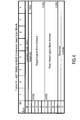
FIG. 4 is a table illustrating a SET-READ-AHEAD command descriptor block of a read command suitable for use in a read method in accordance with the present invention; -
FIG. 5 is a flow diagram schematically illustrating a process of decision-making in a disc drive. -
FIG. 1 is a block diagram schematically illustrating adata storage system 1, comprising adata storage medium 2, amedium access device 10, and ahost device 20. In a typical practical implementation, thehost device 20 may be a suitably programmed personal computer (PC); it is also possible that thedata storage system 1 is implemented as a dedicated user apparatus such as a video recorder, in which case thehost device 20 is the application part of such apparatus. In a specific embodiment, thedata storage medium 2 is implemented as an optical disc, for instance a DVD or a BD, in which case themedium access device 10 is implemented as a disc drive. In the following, the invention will be described specifically for an optical disc implementation, but it is noted that the present invention is not limited to optical discs. - The
optical disc 2 has astorage space 3, which has the form of one or more continuous spiral-shaped tracks or one or more tracks in the form of multiple concentric circles, where information can be stored in the form of a data pattern. Since this technology is commonly known to persons skilled in the art, this technology will not be explained in further detail. - In
FIG. 1 , a host/drive communication link betweenhost device 20 anddisc drive 10 is indicated at 5. Likewise, a drive/disc communication link betweendisc drive 10 anddisc 2 is indicated at 6. The drive/disc communication link 6 represents the physical (optical) read/write operation as well as the physical addressing ofblocks 4 of thestorage space 3. The host/drive communication link 5 represents a data transfer path as well as a command transfer path. -
FIG. 2 is a diagram schematically illustrating that thestorage space 3 is divided into a large number ofblocks 4. Each block has a specific physical address PA. When thehost device 20 wants to access a certain piece of information, it sends a request to thedisc drive 10, indicating the corresponding logical address LA. Thedisc drive 10 comprises amemory 11, which contains information regarding the relationship between logical addresses LA and physical addresses PA, for instance in the form of a look-up table. Based on this information, thedisc drive 10 determines which physical address corresponds to the required logical address. -
FIG. 2 illustrates a typical situation during a reading process. Thehost 20 is receiving information from a first block having a Transfer Block Address TBA, while thedisc drive 10 is already some blocks further, reading the data from a second block having a Read Block Address RBA. It should be understood that thehost 20 is not accessing the first block TBA directly, as the figure suggests, but thehost 20 receives the data from adata buffer 12 of thedisc drive 10. -
FIG. 3A is a diagram schematically illustrating that sectors of a data sequence are not always written in a physically sequential order. In the illustration ofFIG. 3A , a data sequence (for instance a video sequence) comprises sectors A, B, C, which need to be accessed in this order. Assume a host reading the first sector A. Next sector B is the first block after sector A, but third sector C is not located adjacent second sector B, so a jump j1 has to be made. In this case, the jump j1 from second sector B to third sector C is a jump to a higher address. - It is noted that the
track 3 main contain one or more further sectors between sectors B and C, as illustrated, but the storage space between sectors B and C may also be empty. -
FIG. 3B is a diagram comparable toFIG. 3A , illustrating a data sequence (for instance a video sequence) comprising sectors D, E, F, which need to be accessed in this order. Assume a host reading the first sector D. Next sector E is the first block after sector A, but third sector C is not located adjacent second sector B, so a jump j2 has to be made. In this case, the jump j2 from second sector E to third sector F is a jump to a lower address. It is noted that thetrack 3 main contain one or more further sectors between sectors F and D, as illustrated, but the storage space between sectors B and C may also be empty. - In order for the
disc drive 10 to maintain its advance with respect to thehost 20, thedisc drive 10 should also make such jumps j1, j2. However, thedisc drive 10 does not know that thehost 10 will make such jumps, so this information should be communicated from the host to the drive. - For instance, at any time during the reading process of sectors A and B, the
host 20 can send to the disc drive 10 a “read-ahead” command JUMP(B,C). This command is known in the state of the art: in response to this command, since the address of C is higher than the address of B, thedisc drive 10 will jump to sector C when it has completely read sector B. - It is noted that, although in this example sectors A and B are adjacent to each other, the sequence may comprise further sectors between sectors A and B, and the “read-ahead” command JUMP(B,C) may be given at any time before completing the reading of sector B.
- Likewise, the host knows that after sector E it will want to make a jump back to sector F. Thus, the
host 20 will issue a “read-ahead” command JUMP(E,F). In this case, however, since the address of F is lower than the address of E, a priorart disc drive 10 will ignore this command and will return an error message to thehost 20. So, the prior art disc drive will continue reading sector E1 next to sector E. When thehost 20 has actually received all information of the third sector E, it will request the disc drive to read sector F. Thedisc drive 10 will then first have to make a jump to the required track, which takes time, so a continuous data flow may be impossible. - It is noted that, although in this example sectors D and E are adjacent to each other, the sequence may comprise further sectors between sectors D and E, and the “read-ahead” command JUMP(E,F) may be given at any time before completing the reading of sector B.
- According to the invention, the host sends a modified “set-read-ahead” command, indicated as JUMPm(X,Y), which causes the
disc drive 10 to perform the jump, even to a lower address. - There are several practical possibilities envisaged for implementing the modified “set-read-ahead” command JUMPm(X,Y). First, it is of course possible to define an entirely new command. However, it is easier to adapt existing commands of an existing command set. An example of a widely used command set is indicated as MMC3, also indicated as “Mount Fuji” (see, for instance, www.t10.org: “Multimedia
Command Set Version 3 Revision 10G”). In the following, an example of a suitable modified “set-read-ahead” command JUMPm(X,Y) will be described. -
FIG. 4 is a table illustrating a SET READ AHEAD command descriptor block, adapted in accordance with the present invention to comprise a sequential access parameter SAP; therefore, this command will hereinafter also be indicated as JUMPm(X,Y;SAP). It is noted that the sequential access parameter SAP may comprise more than one bit, but one bit suffices. - As illustrated by the table in
FIG. 4 , the SET READ AHEAD command comprises 12 bytes of 8 bits each.Byte 0 contains an operation code, bytes 2-5 are used to indicate the logical block address of the sector from where a jump is to be made (i.e. X), and bytes 6-9 are used to indicate the logical block address of the sector where the jump should end (i.e. Y).Byte 11 is a control byte. -
Bytes - In the embodiment as illustrated in
FIG. 4 , thefirst bit 0 of thesecond byte 1 is used as sequential access parameter SAP. - A
host 20 that is not designed in accordance with the present invention will not set this SAP bit; therefore, such host will always issue a command JUMPm(X,Y;0). Ahost 20 designed in accordance with the present invention may always issue a command JUMPm(X,Y;1). For jumps to a higher address, the host may issue a command JUMPm(X,Y>X;0), but in any case, for jumps to a lower address, the host will always issue a command JUMPm(X,Y<X;1). - A
disc drive 10 that is not designed in accordance with the present invention will not consider the SAP bit, and will behave as before: only commands of type JUMPm(X,Y>X;0) or JUMPm(X,Y>X;1) will be executed, whereas commands of type JUMPm(X,Y<X;0) or JUMPm(X,Y<X;1) will result in an error message. - A
disc drive 10 designed in accordance with the present invention will consider the SAP bit. In case SAP=0, commands of type JUMPm(X,Y>X;0) will be executed, whereas commands of type JUMPm(X,Y<X;0) will result in an error message. In case SAP=1, all commands of type JUMPm(X,Y;1) will be executed, whether Y>X or Y<X. - It is noted that it is not necessary for the
disc drive 10 to consider the SAP bit in case Y>X.FIG. 5 illustrates different possibilities for thedisc drive 10 for executing a decision-making process 50 when receiving a jump command JUMPm(X,Y;SAP) [step 51]. - First, it is possible that the
disc drive 10 considers whether SAP≠0 [step 52]; if so, thedisc drive 10 does not need to compare X and Y but can make the jump X→Y in any case [step 54]. Otherwise, if SAP=0, thedisc drive 10 compares X and Y to check whether Y>X [step 53]; if so, thedisc drive 10 can make the jump X→Y [step 54], otherwise it issues an error message [step 59]. - Alternatively, it is possible that the
disc drive 10 first compares X and Y to check whether Y>X [step 55]; if so, thedisc drive 10 does not need to consider the SAP bit but can make the jump X→Y in any case [step 54]. Otherwise, if Y<X, thedisc drive 10 considers whether SAP≠0 [step 56]; if so, thedisc drive 10 can make the jump X→Y [step 54], otherwise it issues an error message [step 59]. - Thus, it should be clear that the present invention succeeds in providing a
data storage system 1 which comprises: - an
optical disc 2 having astorage space 3 comprisingblocks 4 of storage locations; - a
disc drive 10, suitable for reading information from the disc, the drive being designed to automatically start reading a next block after having read a previous block; - a
host 20, capable of cooperating with the drive; - the host being designed to send commands to said drive, commanding said drive to read one or more sectors of data from said
disc 2; - the host being designed to send a jump command JUMPm(X,Y;SAP) to said drive, for instructing said drive to jump to block Y after having read block X, the jump command JUMPm(X,Y;SAP) including a sequential access parameter SAP;
- the drive being designed, in response to receiving a jump command JUMPm(X,Y<X;SAP≠0), to jump back to block Y after having read block X, the address of block Y being lower than the address of block X.
- It should be clear to a person skilled in the art that the present invention is not limited to the exemplary embodiments discussed above, but that several variations and modifications are possible within the protective scope of the invention as defined in the appending claims.
- In the above, the present invention has been explained with reference to block diagrams, which illustrate functional blocks of the device according to the present invention. It is to be understood that one or more of these functional blocks may be implemented in hardware, where the function of such functional block is performed by individual hardware components, but it is also possible that one or more of these functional blocks are implemented in software, so that the function of such functional block is performed by one or more program lines of a computer program or a programmable device such as a microprocessor, microcontroller, digital signal processor, etc.
Claims (16)
Applications Claiming Priority (4)
| Application Number | Priority Date | Filing Date | Title |
|---|---|---|---|
| EP04104705 | 2004-09-28 | ||
| EP04104705.1 | 2004-09-28 | ||
| EP04104705 | 2004-09-28 | ||
| PCT/IB2005/053079 WO2006035352A1 (en) | 2004-09-28 | 2005-09-20 | Method and device for storing data on a record medium and for transferring information |
Publications (2)
| Publication Number | Publication Date |
|---|---|
| US20080098199A1 true US20080098199A1 (en) | 2008-04-24 |
| US7716418B2 US7716418B2 (en) | 2010-05-11 |
Family
ID=35406282
Family Applications (1)
| Application Number | Title | Priority Date | Filing Date |
|---|---|---|---|
| US11/575,575 Expired - Fee Related US7716418B2 (en) | 2004-09-28 | 2005-09-20 | Method and device for utilizing a modified read-ahead command to store data on a record medium |
Country Status (7)
| Country | Link |
|---|---|
| US (1) | US7716418B2 (en) |
| EP (1) | EP1797561B1 (en) |
| JP (1) | JP4819056B2 (en) |
| KR (1) | KR20070057979A (en) |
| CN (1) | CN101031970B (en) |
| TW (1) | TW200625278A (en) |
| WO (1) | WO2006035352A1 (en) |
Citations (11)
| Publication number | Priority date | Publication date | Assignee | Title |
|---|---|---|---|---|
| US1320035A (en) * | 1919-10-28 | Automatic sound-reproducing- machine | ||
| US5557767A (en) * | 1993-03-31 | 1996-09-17 | Kabushiki Kaisha Toshiba | Disk control system using identification codes for retrieving related data for storage in a read ahead cache |
| US5940351A (en) * | 1991-08-01 | 1999-08-17 | Sony Corporation | Information record medium as well as editing apparatus and reproducing apparatus for the same |
| US6092154A (en) * | 1994-09-14 | 2000-07-18 | Intel Corporation | Method of pre-caching or pre-fetching data utilizing thread lists and multimedia editing systems using such pre-caching |
| US6138147A (en) * | 1995-07-14 | 2000-10-24 | Oracle Corporation | Method and apparatus for implementing seamless playback of continuous media feeds |
| US6185621B1 (en) * | 1997-03-25 | 2001-02-06 | Philips Electronics N.A. Corp. | Direct copying between disk blocks in memory onto a network as sequential access files |
| US6260143B1 (en) * | 1998-07-27 | 2001-07-10 | Oak Technology, Inc. | Host-based caching method and system for copy protected content |
| US6381404B1 (en) * | 1999-01-28 | 2002-04-30 | Oak Technology, Inc. | Memory efficient method and apparatus for reading and caching of DVD data |
| US6484235B1 (en) * | 1999-05-03 | 2002-11-19 | 3Ware, Inc. | Methods and systems for dynamically distributing disk array data accesses |
| US20030210617A1 (en) * | 2002-05-13 | 2003-11-13 | Millikan Thomas N. | Shock protection for compressed audio on a CD player |
| US20040049640A1 (en) * | 2002-09-09 | 2004-03-11 | Kimming So | System and method for directional prefetching |
Family Cites Families (3)
| Publication number | Priority date | Publication date | Assignee | Title |
|---|---|---|---|---|
| JPH10214459A (en) * | 1997-01-31 | 1998-08-11 | Matsushita Electric Ind Co Ltd | Optical disk drive device and optical disk reproducing method |
| JPH11167763A (en) * | 1997-08-29 | 1999-06-22 | Sanyo Electric Co Ltd | Optical disk reproducing device |
| EP1320035A1 (en) * | 2001-12-11 | 2003-06-18 | Thomson Licensing S.A. | Storage device cache management |
-
2005
- 2005-09-20 EP EP05784492A patent/EP1797561B1/en not_active Not-in-force
- 2005-09-20 US US11/575,575 patent/US7716418B2/en not_active Expired - Fee Related
- 2005-09-20 CN CN2005800328443A patent/CN101031970B/en not_active Expired - Fee Related
- 2005-09-20 JP JP2007533031A patent/JP4819056B2/en not_active Expired - Fee Related
- 2005-09-20 WO PCT/IB2005/053079 patent/WO2006035352A1/en active Application Filing
- 2005-09-20 KR KR1020077009347A patent/KR20070057979A/en not_active Application Discontinuation
- 2005-09-23 TW TW094133101A patent/TW200625278A/en unknown
Patent Citations (12)
| Publication number | Priority date | Publication date | Assignee | Title |
|---|---|---|---|---|
| US1320035A (en) * | 1919-10-28 | Automatic sound-reproducing- machine | ||
| US5940351A (en) * | 1991-08-01 | 1999-08-17 | Sony Corporation | Information record medium as well as editing apparatus and reproducing apparatus for the same |
| US5557767A (en) * | 1993-03-31 | 1996-09-17 | Kabushiki Kaisha Toshiba | Disk control system using identification codes for retrieving related data for storage in a read ahead cache |
| US6092154A (en) * | 1994-09-14 | 2000-07-18 | Intel Corporation | Method of pre-caching or pre-fetching data utilizing thread lists and multimedia editing systems using such pre-caching |
| US6138147A (en) * | 1995-07-14 | 2000-10-24 | Oracle Corporation | Method and apparatus for implementing seamless playback of continuous media feeds |
| US6185621B1 (en) * | 1997-03-25 | 2001-02-06 | Philips Electronics N.A. Corp. | Direct copying between disk blocks in memory onto a network as sequential access files |
| US6578070B1 (en) * | 1997-10-22 | 2003-06-10 | Ncube Corporation | Method and apparatus for implementing seamless playback of continuous media feeds |
| US6260143B1 (en) * | 1998-07-27 | 2001-07-10 | Oak Technology, Inc. | Host-based caching method and system for copy protected content |
| US6381404B1 (en) * | 1999-01-28 | 2002-04-30 | Oak Technology, Inc. | Memory efficient method and apparatus for reading and caching of DVD data |
| US6484235B1 (en) * | 1999-05-03 | 2002-11-19 | 3Ware, Inc. | Methods and systems for dynamically distributing disk array data accesses |
| US20030210617A1 (en) * | 2002-05-13 | 2003-11-13 | Millikan Thomas N. | Shock protection for compressed audio on a CD player |
| US20040049640A1 (en) * | 2002-09-09 | 2004-03-11 | Kimming So | System and method for directional prefetching |
Also Published As
| Publication number | Publication date |
|---|---|
| EP1797561B1 (en) | 2012-06-06 |
| CN101031970B (en) | 2013-03-27 |
| WO2006035352A1 (en) | 2006-04-06 |
| JP4819056B2 (en) | 2011-11-16 |
| EP1797561A1 (en) | 2007-06-20 |
| CN101031970A (en) | 2007-09-05 |
| TW200625278A (en) | 2006-07-16 |
| JP2008515123A (en) | 2008-05-08 |
| KR20070057979A (en) | 2007-06-07 |
| US7716418B2 (en) | 2010-05-11 |
Similar Documents
| Publication | Publication Date | Title |
|---|---|---|
| RU2269829C2 (en) | Method for recording digital information signals on disk data carrier, method for reproducing digital information signals on disk data carrier, recording device and computer data system for recording digital information signals on data carrier (variants) | |
| JP4744569B2 (en) | Recording method and reproducing method suitable for recording / reproducing AV data, recording drive and reproducing drive thereof, information recording system, information reproducing system, and information recording medium | |
| KR100531401B1 (en) | Recording and reproducing apparatus | |
| US7324422B2 (en) | Information storage method that assures compatibility of writable medium with read only medium | |
| US8081396B2 (en) | Processing data recorded on a tape medium | |
| US20050030795A1 (en) | Information recording device, information recording method, information recording program, and recording medium | |
| US20090279417A1 (en) | Information recording apparatus | |
| US20080098051A1 (en) | Managing Data Space on a Record Carrier | |
| US7716418B2 (en) | Method and device for utilizing a modified read-ahead command to store data on a record medium | |
| JPH10106170A (en) | Optical disk information recording system | |
| JP2003263842A (en) | Information recorder | |
| CN101159141B (en) | Data recording and reproducing apparatus, data recording and reproducing method | |
| JP2008503847A (en) | Managing defects at the file level | |
| US20100180149A1 (en) | Method and device for storing/reading data on/from a record medium and for transferring information to/from it | |
| JP4196512B2 (en) | Recording method and reproducing method suitable for recording / reproducing AV data, recording drive and reproducing drive thereof, information recording system, information reproducing system, and information recording medium | |
| US7800983B2 (en) | Method and apparatus to record data to minimize a layer jump | |
| US8560769B2 (en) | Interruptible formatting | |
| US20060239156A1 (en) | Recording/reproducing method and disc | |
| US7406011B2 (en) | Recording medium and methods of and device for recording information on the recording medium | |
| JP2004206748A (en) | Program and computer-readable recording medium | |
| JPH1064066A (en) | Optical disk information recording system | |
| JP2003228919A (en) | Information recording and reproducing device, method and program for controlling information recording and reproduction, and storage medium | |
| JP2004227689A (en) | Information reproducing device | |
| JP2002208256A (en) | Information recording method | |
| JPH09223359A (en) | Control system for information recording and reproducing |
Legal Events
| Date | Code | Title | Description |
|---|---|---|---|
| AS | Assignment |
Owner name: KONINKLIJKE PHILIPS ELECTRONICS N V, NETHERLANDS Free format text: ASSIGNMENT OF ASSIGNORS INTEREST;ASSIGNORS:VAN BECKHOVEN, STEPHANUS JOSEPHUS MARIA;BRONDIJK, ROBERT ALBERTUS;IJTSMA, POPE;AND OTHERS;REEL/FRAME:019034/0071 Effective date: 20060424 Owner name: KONINKLIJKE PHILIPS ELECTRONICS N V,NETHERLANDS Free format text: ASSIGNMENT OF ASSIGNORS INTEREST;ASSIGNORS:VAN BECKHOVEN, STEPHANUS JOSEPHUS MARIA;BRONDIJK, ROBERT ALBERTUS;IJTSMA, POPE;AND OTHERS;REEL/FRAME:019034/0071 Effective date: 20060424 |
|
| STCF | Information on status: patent grant |
Free format text: PATENTED CASE |
|
| FPAY | Fee payment |
Year of fee payment: 4 |
|
| MAFP | Maintenance fee payment |
Free format text: PAYMENT OF MAINTENANCE FEE, 8TH YEAR, LARGE ENTITY (ORIGINAL EVENT CODE: M1552) Year of fee payment: 8 |
|
| FEPP | Fee payment procedure |
Free format text: MAINTENANCE FEE REMINDER MAILED (ORIGINAL EVENT CODE: REM.); ENTITY STATUS OF PATENT OWNER: LARGE ENTITY |
|
| LAPS | Lapse for failure to pay maintenance fees |
Free format text: PATENT EXPIRED FOR FAILURE TO PAY MAINTENANCE FEES (ORIGINAL EVENT CODE: EXP.); ENTITY STATUS OF PATENT OWNER: LARGE ENTITY |
|
| STCH | Information on status: patent discontinuation |
Free format text: PATENT EXPIRED DUE TO NONPAYMENT OF MAINTENANCE FEES UNDER 37 CFR 1.362 |
|
| FP | Lapsed due to failure to pay maintenance fee |
Effective date: 20220511 |