US20080098188A1 - Remote copy method and remote copy system - Google Patents
Remote copy method and remote copy system Download PDFInfo
- Publication number
- US20080098188A1 US20080098188A1 US11/585,747 US58574706A US2008098188A1 US 20080098188 A1 US20080098188 A1 US 20080098188A1 US 58574706 A US58574706 A US 58574706A US 2008098188 A1 US2008098188 A1 US 2008098188A1
- Authority
- US
- United States
- Prior art keywords
- data
- storage system
- storage
- logical volume
- written
- Prior art date
- Legal status (The legal status is an assumption and is not a legal conclusion. Google has not performed a legal analysis and makes no representation as to the accuracy of the status listed.)
- Granted
Links
Images


Classifications
-
- G—PHYSICS
- G06—COMPUTING; CALCULATING OR COUNTING
- G06F—ELECTRIC DIGITAL DATA PROCESSING
- G06F11/00—Error detection; Error correction; Monitoring
- G06F11/07—Responding to the occurrence of a fault, e.g. fault tolerance
- G06F11/16—Error detection or correction of the data by redundancy in hardware
- G06F11/20—Error detection or correction of the data by redundancy in hardware using active fault-masking, e.g. by switching out faulty elements or by switching in spare elements
- G06F11/2053—Error detection or correction of the data by redundancy in hardware using active fault-masking, e.g. by switching out faulty elements or by switching in spare elements where persistent mass storage functionality or persistent mass storage control functionality is redundant
- G06F11/2056—Error detection or correction of the data by redundancy in hardware using active fault-masking, e.g. by switching out faulty elements or by switching in spare elements where persistent mass storage functionality or persistent mass storage control functionality is redundant by mirroring
- G06F11/2071—Error detection or correction of the data by redundancy in hardware using active fault-masking, e.g. by switching out faulty elements or by switching in spare elements where persistent mass storage functionality or persistent mass storage control functionality is redundant by mirroring using a plurality of controllers
- G06F11/2074—Asynchronous techniques
-
- G—PHYSICS
- G06—COMPUTING; CALCULATING OR COUNTING
- G06F—ELECTRIC DIGITAL DATA PROCESSING
- G06F11/00—Error detection; Error correction; Monitoring
- G06F11/07—Responding to the occurrence of a fault, e.g. fault tolerance
- G06F11/16—Error detection or correction of the data by redundancy in hardware
- G06F11/20—Error detection or correction of the data by redundancy in hardware using active fault-masking, e.g. by switching out faulty elements or by switching in spare elements
- G06F11/2053—Error detection or correction of the data by redundancy in hardware using active fault-masking, e.g. by switching out faulty elements or by switching in spare elements where persistent mass storage functionality or persistent mass storage control functionality is redundant
- G06F11/2056—Error detection or correction of the data by redundancy in hardware using active fault-masking, e.g. by switching out faulty elements or by switching in spare elements where persistent mass storage functionality or persistent mass storage control functionality is redundant by mirroring
- G06F11/2066—Optimisation of the communication load
-
- G—PHYSICS
- G06—COMPUTING; CALCULATING OR COUNTING
- G06F—ELECTRIC DIGITAL DATA PROCESSING
- G06F2201/00—Indexing scheme relating to error detection, to error correction, and to monitoring
- G06F2201/855—Details of asynchronous mirroring using a journal to transfer not-yet-mirrored changes
-
- Y—GENERAL TAGGING OF NEW TECHNOLOGICAL DEVELOPMENTS; GENERAL TAGGING OF CROSS-SECTIONAL TECHNOLOGIES SPANNING OVER SEVERAL SECTIONS OF THE IPC; TECHNICAL SUBJECTS COVERED BY FORMER USPC CROSS-REFERENCE ART COLLECTIONS [XRACs] AND DIGESTS
- Y10—TECHNICAL SUBJECTS COVERED BY FORMER USPC
- Y10S—TECHNICAL SUBJECTS COVERED BY FORMER USPC CROSS-REFERENCE ART COLLECTIONS [XRACs] AND DIGESTS
- Y10S707/00—Data processing: database and file management or data structures
- Y10S707/99951—File or database maintenance
- Y10S707/99952—Coherency, e.g. same view to multiple users
- Y10S707/99953—Recoverability
-
- Y—GENERAL TAGGING OF NEW TECHNOLOGICAL DEVELOPMENTS; GENERAL TAGGING OF CROSS-SECTIONAL TECHNOLOGIES SPANNING OVER SEVERAL SECTIONS OF THE IPC; TECHNICAL SUBJECTS COVERED BY FORMER USPC CROSS-REFERENCE ART COLLECTIONS [XRACs] AND DIGESTS
- Y10—TECHNICAL SUBJECTS COVERED BY FORMER USPC
- Y10S—TECHNICAL SUBJECTS COVERED BY FORMER USPC CROSS-REFERENCE ART COLLECTIONS [XRACs] AND DIGESTS
- Y10S707/00—Data processing: database and file management or data structures
- Y10S707/99951—File or database maintenance
- Y10S707/99952—Coherency, e.g. same view to multiple users
- Y10S707/99955—Archiving or backup
Definitions
- the present invention relates to a storage system, and in particular to copying of data among plural storage systems.
- first storage system a storage system used for providing continuous services to customers
- other storage systems a storage system a relatively short distance apart from the first storage system is referred to as a second storage system, and a storage system a longer distance apart from the second storage system is referred to as a third storage system
- copies of data in the first storage system are stored in the other storage systems.
- U.S. Pat. No. 6,209,002 discloses a technique in which the second storage system has two copied data corresponding to copy object data in the first storage system, and the third storage system holds one of the copied data.
- JP-A-2003-122509 discloses a technique in which the second storage system has only one copied data corresponding to copy object data in the first storage system, and the third storage system can obtain the copied data without requiring a redundant logical volume for carrying out remote copy as described in U.S. Pat. No. 6,209,002.
- the second storage system is provided between the first storage system and the third storage system, which is located a long distance apart from the first storage system, to realize long-distance remote copy while preventing data loss such that a copy of data in the first storage system is obtained in the third storage system.
- a remote copy system in which cost for system operation is considered while failure resistance of data is increased through long-distance copying.
- a copy of data in the first storage system only has to be held in a storage system located a long distance apart from the first storage system.
- the second storage system is required to have a volume (copied volume) that is the same as a volume of the first storage system. This volume increases as a capacity of the volume of the first storage system increases.
- the present invention has been devised in view of such problems, and it is an object of the present invention to minimize or eliminate use of a volume in a second storage system for copying data when the data is copied from a first site to a third site. In addition, it is another object of the present invention to increase availability of a volume such that plural host apparatuses can set an area of the volume as an object of writing.
- a form of the present invention has a constitution described below.
- a remote copy system includes: a first storage system that sends and receives data to and from a first information processing apparatus; a second storage system that is connected to a second information processing apparatus and the first storage system and receives data from the first storage system; and a third storage system that is connected to the second storage system and receives data from the second storage system.
- the first storage system has a first storage area in which data from an information processing apparatus is written
- the second storage system has a logical address for storing a copy of the data but does not have an allocated storage area, and has a second storage area in which the data and update information thereof are written, the data sent from the first storage system is written in the second storage area as the data and the update information
- the third storage system has a third storage area in which data read out from the second storage area in the second storage system and update information concerning the data are stored, and the data and the update information stored in the second storage area are readout from the third storage system.
- the second storage system has a logical address for storing a copy of the data but does not have an allocated storage area
- the storage area has a structure that can be used for transmission and reception of data to and from a second information processing apparatus.
- a copy object data can be copied to the third storage system without requiring the second storage system to have a complete copy of the copy object data in the first storage system. Consequently, a volume capacity in the second storage system can be reduced.
- an actual volume which is not required to be assigned, can be used for another application.
- a specific area of a volume can be used by plural host apparatuses.
- the host apparatus in this context means an information processing apparatus that issues instructions for writing data in and reading data from the specific area of the volume.
- the first storage system is a host apparatus for the second storage system. It is needless to mention that an information processing apparatus such as a server can be a host apparatus for a storage system.
- FIG. 1 is a block diagram showing a first embodiment of the present invention
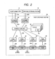
- FIG. 2 is a block diagram showing an internal structure of a storage system
- FIG. 3 is a diagram showing a volume information table
- FIG. 4 is a diagram for explaining a journal
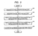
- FIG. 5 is a flowchart showing initial copy processing
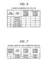
- FIG. 6 is a diagram showing pair setting information
- FIG. 7 is a diagram showing a journal group setting information table
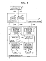
- FIG. 8 is a block diagram showing a flow of access instruction reception processing
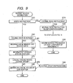
- FIG. 9 is a flowchart explaining the access instruction reception processing
- FIG. 10 is a block diagram showing an operation (journal read reception processing) of a channel adapter 50 of a storage system 15 that has received a journal read instruction;
- FIG. 11 is a flowchart explaining journal read instruction reception processing
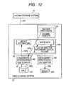
- FIG. 12 is a block diagram showing restore processing
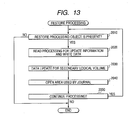
- FIG. 13 is a flowchart showing the restore processing
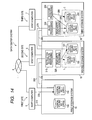
- FIG. 14 is a block diagram showing a second embodiment of the present invention.
- FIG. 15 is a flowchart showing initial setting processing in the second embodiment
- FIG. 16 is a diagram showing pair setting information
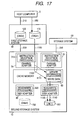
- FIG. 17 is a block diagram showing a flow of access instruction reception processing in the second embodiment
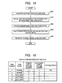
- FIG. 18 is a flowchart showing the access instruction reception processing in the second embodiment
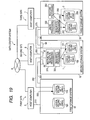
- FIG. 19 is a block diagram showing a third embodiment of the present invention.
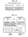
- FIG. 20 is a diagram showing a connection information table
- FIG. 21 is a diagram showing an example of a setting screen for pair generation that is displayed on a host computer or a maintenance terminal in a fourth embodiment of the present invention.
- FIG. 22 is a block diagram showing a case in which a job is taken over by a third site when a failure has occurred in a first site.
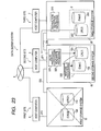
- FIG. 23 is a block diagram showing a case in which a job is taken over by a second site when a failure has occurred in the first site.
- FIG. 1 is a block diagram showing a first embodiment of the present invention.
- FIG. 1 shows an entire remote copy system including plural storage systems.
- a storage system 10 is connected to a host computer 5 via a connection line 210 .
- this storage system 10 will be hereinafter referred to as a first storage system, and a data processing system including this first storage system and the host computer 5 will be hereinafter referred to as a first site.
- a storage system 15 is connected to the first storage system 10 via a connection line 220 .
- this storage system 15 will be hereinafter referred to as a second storage system, and a data processing system including at least this second storage system will be hereinafter referred to as a second site or an intermediate site.
- a storage system 20 is connected to the storage system 15 serving as the second storage system via a connection line 240 .
- this storage system 20 will be hereinafter referred to as a third storage system, and a data processing system including at least this third storage system 20 will be hereinafter referred to as a third site.
- connection lines 210 , 220 , and 240 may be directly connected lines such as fiber cables or may be connection via a wide-area network such as the Internet.
- the storage system 10 in the first site retains a logical volume 110 (ORG 1 ) and a logical volume 120 (ORG 2 ).
- ORG 1 a logical volume 110
- ORG 2 a logical volume 120
- an original data to be a copy object is stored in the logical volume 110 (ORG 1 ).
- the storage system 15 in the second site retains a copy of the logical volume 110 (ORG 1 ) as a logical volume 150 (Data 1 ).
- the storage system 20 in the third site retains a logical volume 200 (Data 2 ) in which copied data is stored.
- a capacity and a physical storage position (physical address) of a logical volume which are defined in the storage systems 10 , 15 , and 20 , can be designated using maintenance terminals (not shown) such as computers connected to the respective storage systems or host computers 5 , 6 , and 7 , respectively.
- a logical volume, in which the copy object data is accumulated will be referred to as a primary logical volume
- a logical volume, in which the copied data is accumulated will be referred to as a secondary logical volume.
- the primary logical volume and the secondary logical volume forming a pair will be referred to as a pair.
- a relation between the primary logical volume and the secondary logical volume, states of the primary logical volume and the secondary logical volume, and the like are saved as a pair setting information table 500 in shared memories (SMs) 70 in the respective storage systems to be described later.
- SMs shared memories
- the second storage system which is shown as the storage system 15 in FIG. 1 , is simply illustrated as the second storage system 15 in FIG. 2 .
- the first storage system 10 has plural channel adapters 50 for connecting the first storage system 10 to the host computer 5 . These channel adapters 50 are connected to the host computer 5 and the second storage system 15 via the connection line 210 .
- the channel adapters 50 are connected to caches 60 via a connection unit 55 , analyzes a command received from a host apparatus, and controls reading-out and writing of data, which is desired by the host computer 5 , on the caches 60 .
- the logical volume 110 (ORG 1 ) and the logical volume 120 (ORG 2 ) are arranged over plural HDDs 100 .
- FIG. 3 shows an example of a table in which logical volumes and physical addresses on the HDDs 100 are defined, and capacities, attribute information such as formats, and pair information of the logical volumes are defined.
- logical volume numbers are treated as unique to respective logical volumes in a data center.
- logical volume numbers so as to be uniquely defined by a unit of each storage system and specified in conjunction with identifiers of the storage systems.
- “Not used” in a volume state indicates that a logical volume is set but is not used yet.
- “Primary” indicates that a logical volume is in a state in which the logical volume can operate normally as the primary volume of the pair volume described above.
- “Normal” indicates that a logical volume is not set as a pair with another logical volume but is in a normal state.
- Secondary indicates that a logical volume is a secondary volume and can operate normally. Volume state information indicating a state of a pair will be described later.
- FIG. 3 represents states of logical volumes in a data center system of this application.
- a logical volume number 1 indicates the logical volume 110 (ORG 1 ) of the first storage system 10
- a logical volume number 2 indicates a state in which the logical volume 150 (Data 1 ) of the second storage system 15 and the pair number 1 form a pair.
- a logical volume 151 (JNL 1 ) of the second storage system 15 is represented as a logical volume number 3
- a logical volume 201 of the third storage system 20 is represented as a logical volume number 4
- a logical volume 200 of the third storage system 20 is represented as a logical volume number 5 .
- the logical volume 120 (ORG 2 ) is defined as a logical volume number 6 .
- a column of a physical address in FIG. 3 indicates addresses on the actual HDDs 100 .
- microprocessors (not shown) on disk adapters 80 in FIG. 2 controls an operation for recording data on the actual HDDs 100 from the caches 60 and an operation for reading out data from the HDDs 100 to the caches 60 .
- the storage system 10 is described above as a representative storage system. However, the other storage systems 15 and 20 shown in FIG. 1 also have substantially the same structure.
- the connection unit 55 may be constituted by a switch or the like for directly connecting channel adapters and caches or the like or may adopt a connection system using a bus. Note that FIG. 2 shows a state in which there are the shared memories 70 in the caches 60 . However, the shared memories 70 may be connected to the connection unit 55 separately from the caches 60 .
- journal data a logical volume of an update source, in which data is updated, is distinguished from the other logical volumes to be referred to as a source logical volume, and a volume, which retains a copy of the update source logical volume, is referred to as a copy logical volume.
- the journal data consists of, when data update is applied to a certain source logical volume, at least updated data itself and update information indicating to which position of the source logical volume the update is applied (e.g., a logical address on the source logical volume).
- journal data is retained when data in the source logical volume is updated, the source logical volume can be reproduced from the journal data.
- journal data the data image of the source logical volume can be reproduced in the copy logical volume without requiring the same capacity as the source logical volume.
- a volume in which the journal data is retained will be hereinafter referred to as a journal logical volume.
- FIG. 4 shows a state in which data from addresses 700 to 1000 of a certain source logical volume is updated (updated data 630 ).
- data itself updated as the journal data 950 is recorded in a write data area 9100 as write data 610
- information relating to update for example, information indicating which position is updated is recorded as update information 620 in an update information area 9000 .
- the journal logical volume is used in a state in which it is divided into a storage area 9000 (update information area), in which the update information 620 is stored, and a storage area 9100 (write data area), in which write data is stored.
- Update information is stored in the update information area 9000 in an order of update (an order of an update number) from the top of the update information area 9000 .
- the update information is stored from the top of the update information area 9000 .
- Write data is stored in the write data area 9100 from the top of the write data area 9100 .
- the write data is stored from the top of the write data area 9100 .
- a ratio of the update information area 9000 and the write data area 9100 may be a fixed value or may be set by the maintenance terminal or the host computer 5 .
- FIG. 1 when the storage system 10 receives a write instruction for the data in the primary logical volume 10 (ORG 1 ) in the storage system 10 from the host computer 5 (arrow 250 shown in FIG. 1 ), the data in the primary logical volume 110 (ORG 1 ) in the first storage system 10 is updated. Then, the logical volume 150 (Data 1 ) in the storage system 15 in the second site (intermediate site), which forms a pair with the updated primary logical volume 110 (ORG 1 ), is updated in the same manner (update of a synchronized pair). Consequently, the second storage system 15 can take over the job immediately even if a failure has occurred in the first storage system 10 . This is because the second storage system 15 retains the secondary logical volume 150 (Data 1 ) having the same data image as the primary logical volume 110 (ORG 1 ) used by the host computer 5 .
- journal volume when data update is applied to the logical volume 150 (Data 1 ), the storage system 15 in the second site saves journal data in the logical volume 151 (JNL 1 ) (hereinafter referred to as a journal volume according to circumstances) (arrow 260 shown in FIG. 1 ).
- the journal data which is accumulated in the logical volume 151 (JNL 1 ) for accumulation of journal data in the second storage system 15 , is asynchronously transferred to the logical volume 201 (JNL 2 ) for journal accumulation in the third storage system 20 located a long distance apart from the second storage system 15 via the connection line 240 (arrow 270 shown in FIG. 1 ) (hereinafter referred to as a PUSH system).
- the third storage system 20 reproduces the logical volume 200 (Data 2 ) corresponding to the logical volume 150 in the second storage system 15 using the journal data in the journal volume 201 (JNL 2 ) in the storage system 20 (arrow 280 shown in FIG. 1 , restore processing).
- the data in the journal volume in the second storage system 15 may be read out from the third storage system 20 and accumulated in the logical volume 201 (JNL 2 ) in the storage system 20 (hereinafter referred to as PULL system).
- journal read instruction an instruction to read journal data (hereinafter referred to as journal read instruction) from the third storage system 20
- the second storage system 15 Upon receiving an instruction to read journal data (hereinafter referred to as journal read instruction) from the third storage system 20 , the second storage system 15 reads out journal data from the journal logical volume 151 (JNL 1 ) and sends the journal data to the third storage system 20 .
- the third storage system 20 reads out the journal data from the journal logical volume (JNL 2 ) 201 according to restore processing 350 to be described later and updates the data in the logical volume 200 (Data 2 ). This completes the processing for reflecting the data update, which is carried out for the primary logical volume 110 (ORG 1 ) in the storage system 10 in the first site, on the secondary logical volume 200 (Data 2 ) in the storage system 20 in the third site.
- journal data By saving the journal data in the journal volume 201 , for example, it is also possible not to perform data update for the secondary logical volume 200 (Data 2 ) when the journal data is received, that is, not to create a copy of the primary logical volume 110 (ORG 1 ) in the secondary logical volume 200 (Data 2 ) using the journal data (restore processing 350 ) when a load of the storage system 20 is high, and update the data in the secondary logical volume 200 (Data 2 ) after a short time when a load of the storage system 20 is low.
- data update for the secondary logical volume 200 (Data 2 ) when the journal data is received that is, not to create a copy of the primary logical volume 110 (ORG 1 ) in the secondary logical volume 200 (Data 2 ) using the journal data (restore processing 350 ) when a load of the storage system 20 is high, and update the data in the secondary logical volume 200 (Data 2 ) after a short time when a load of the storage system 20 is low.
- the logical volume 151 (JNL 1 ) in the second storage system 15 shown in FIG. 1 is a storage area dedicated for journal data and can be made smaller than a storage area that is a data copy object. This makes it possible to copy data to the second and the third storage systems 15 and 20 from the first storage system 10 by controlling consumption of a storage area in the second storage system 15 .
- This setting is adopted in performing an operation for reflecting the data update for the logical volume 110 (ORG 1 ) in the storage system 10 on the second storage system 15 in the intermediate site and the third storage system 20 in the third site.
- journal group means a pair of logical volumes.
- the journal group consists of a logical volume and a journal volume in which, when an instruction to write data in the logical volume is received, the write instruction is sectioned into update information such as a write destination address and write data and accumulated.
- the logical volume 150 (Data 1 ) and the logical volume 151 (JNL 1 ) form a journal group in the storage system 15
- the logical volume 201 (JNL 2 ) and the logical volume 200 (Data 2 ) form a journal group in the storage system 20 .
- FIG. 5 shows an initial setting procedure of the data center system of the present invention.
- a user sets journal groups for the respective storage systems using GUIs (graphical user interfaces) included in the host computers 5 , 6 and 7 or the maintenance terminals not shown in FIG. 1 (steps 900 and 905 ).
- GUIs graphical user interfaces
- journal groups in the storage system 15 and the storage system 20 in the second and the third sites that is, the pair of Data 1 and JNL 1 and the pair of Data 2 and JNL 2 are referred to as a journal group 1 and a journal group 2 , respectively.
- the journal groups may be referred to as journal pairs. More specifically, the journal groups are retained in the shared memories 70 as a journal group setting information table 550 .
- the user designates information indicating a data copy object and information indicating a data copy destination and sends a pair registration instruction to the first and the second storage systems 10 and 15 using the maintenance terminals or the host computers 5 and 6 connected to the respective storage systems (step 910 ). More specifically, the user sets a pair relation between the logical volume 110 (ORG 1 ) and the logical volume 150 (Data 1 ) in FIG. 1 .
- write processing applied to a primary logical volume serves as an opportunity for performing various kinds of processing with respect to a secondary logical volume.
- the status of the pair includes a suspend state, a pair state, an initial copy state, and the like.
- the status of the pair is the pair state, processing for writing data, which is written in the primary logical volume, in the secondary logical volume as well is performed.
- setting information for the journal group and setting information for this pair are accumulated in the shared memories (SMs) 70 shown in FIG. 2 .
- the microprocessors on the channel adapters 50 execute processing on the basis of the information. It is needless to mention that, in this processing, the shared memories (SMs) 70 do not necessarily have to be referred to every time the processing is performed, and information necessary for processing for a channel processor may be transferred onto a local memory of the channel processor in advance.
- FIG. 6 shows an example of a pair setting information table 500 showing states of pairs.
- a first row of FIG. 6 indicates that a pair of the logical volume 110 (ORG 1 ) (logical volume number 1 ) in the first storage system 10 and the logical volume 150 (Data 1 ) (logical volume number 2 ) in the second storage system 15 is generated as a pair number 1 .
- initial copy which is initialization processing for making data images of the logical volume 110 (ORG 1 ) and the logical volume 150 (Data 1 ) identical, is further performed.
- step 915 the user designates the logical volume 150 (Data 1 ) and the logical volume 200 (Data 2 ) to form a pair and performs initial copy. This is for giving the identical data image to the logical volume 150 (Data 1 ) and the logical volume 200 (Data 2 ) as in the processing in step 910 .
- a row of a pair number 2 in FIG. 6 shows a state in which this pair is set. This pair is deleted after the initial copy processing ends (step 920 ).
- FIG. 8 is a block diagram showing data write processing that is performed by the storage system 15 in the second site.
- the second storage system 15 is connected to the storage system 10 in the first site by the connection line 200 via the channel adapter 50 .
- the first storage system 10 is connected to the host computer 5 via the connection line 210 .
- the first storage system 10 receives a data write instruction from the host computer 5 via the connection line 210 (arrow 250 in FIG. 8 ).
- the second storage system 15 receives the data write instruction from the first storage system 10 via the connection line 220 .
- An arrow 1100 shown in FIG. 8 indicates a flow of data in the case in which the data write instruction for writing data in the logical volume 150 (Data 1 ) of a data copy destination in the storage system 15 in the second site is received.
- the channel adapter 50 Upon receiving the data write instruction for writing data in the logical volume 150 (Data 1 ) from the first storage system, the channel adapter 50 retains the write data and update information in the cache memory 60 . The write data on the cache 60 is written in the logical volume 150 (Data 1 ) by the disk adapter 80 at timing different from timing for writing data in the cache 60 (arrow 1110 in FIG. 8 ).
- the update information (including at least an updated address) recorded on the cache 60 is written in an update information area of the logical volume 151 (JNL 1 ), and the write data is further accumulated in a write data area of the logical volume 151 (JNL 1 ) (arrow 1120 in FIG. 8 ).
- the disk adapter 80 writes the write data and the update information on the cache 60 in an address allocated to the logical volume 151 (JNL 1 ) on the HDD (arrows 1130 and 1140 in FIG. 8 ).
- a channel adapter 51 which is connected to the third storage system 20 via the connection line 240 , receives a read instruction for the logical volume 151 (JNL 1 ) from the storage system 20 .
- JNL 1 the logical volume 151
- the channel adapters 50 and 51 are channel adapters of the same structure but are given different numbers according to circumstances for convenience of explanation.
- FIG. 9 is a flowchart showing processing in the case in which the logical volume 150 (Data 1 ) in the storage system 15 in the second site receives an instruction from the storage system 10 in the first site.
- the microprocessor mounted on the channel adapter 50 in FIG. 8 Upon receiving an access instruction from the first storage system 10 , the microprocessor mounted on the channel adapter 50 in FIG. 8 (hereinafter simply referred to as channel adapter 50 ) checks a type of the instruction (step 1210 in FIG. 9 ). This is because a channel adapter may receive a write instruction as in the channel adapter 50 in FIG. 8 or may receive a read instruction from another storage as in the channel adapter 51 .
- the channel adapter 50 performs journal read reception processing to be described later (steps 1215 and 1220 ).
- the channel adapter 50 checks a volume state of the logical volume 150 (Data 1 ) (step 1240 ).
- states of the respective logical volumes are accumulated in the shared memories (SMs) 70 as volume information in a table format as described above.
- the channel adapter 50 informs the host computer 5 of abnormality and ends the processing (step 1230 ).
- the channel adapter 50 reserves the cache memory 60 and receives data (step 1250 ). More specifically, the channel adapter 50 informs the first storage system 10 that the channel adapter 50 is prepared for receiving data. Thereafter, the first storage system 10 sends write data to the second storage system 15 . The channel adapter 50 in the second storage system 15 receives the write data and saves the write data in the prepared cache memory 60 (step 1250 , arrow 1100 in FIG. 8 ). Thereafter, in step 1260 , the channel adapter 50 informs the first storage system 10 of the end of the processing.
- the channel adapter 50 checks whether the logical volume 150 (Data 1 ) is a logical volume having a journal group with reference to the journal group setting information table 550 (see FIG. 7 ) recorded in the shared memories (SMs) 70 (step 1270 ).
- FIG. 7 is a diagram showing how journal pairs are formed among logical volumes.
- a first row indicates that logical volumes with logical volume numbers 2 and 3 form a journal group. More specifically, the first row indicates that the logical volume 150 (Data 1 ) and the logical volume 151 (JNL 1 ) in the storage system 15 form a journal pair.
- the channel adapter 50 applies, journal creation processing to this volume and the journal logical volume 151 (JNL 1 ) forming the journal group (step 1265 ). Thereafter, at arbitrary timing, the disk adapter 80 writes data in the logical volume 150 (Data 1 ) and the logical volume 151 (JNL 1 ) that are defined on the HDD (step 1280 , arrows 1130 and 1140 in FIG. 8 ).
- journal data is sequentially stored in the journal volume 151 (JNL 1 ).
- the journal data is sent to the journal volume 201 (JNL 2 ) in the third storage system 20 with a fixed factor as an opportunity.
- One method for sending the journal data is the PUSH system described above, and there is the PULL system as another method. The PULL system will be explained with reference to FIG. 10 .
- FIG. 10 is a block diagram showing an operation (journal read instruction reception processing) of the channel adapter 51 in the second storage system 15 that has received a journal read instruction.
- FIG. 11 is a flowchart of the operation. An operation in the case in which the second storage system 15 has received the journal read instruction from the third storage system 20 will be explained with reference to FIGS. 10 and 11 .
- the channel adapter 51 in the second storage system 15 receives an access instruction from the third storage system 20 (arrow 1410 in FIG. 10 ).
- the access instruction is a journal read instruction
- the channel adapter 51 checks whether a journal group state is “normal” with reference to FIG. 7 (step 1510 ). If the journal group state is a state other than “normal”, for example, “failure”, the channel adapter 51 informs the third storage system 20 of the journal group state and ends the processing.
- the third storage system 20 performs processing according to the informed journal group state. For example, if the journal group state is “failure”, the channel adapter 51 ends the journal read processing (step 1515 ).
- journal group state is “normal” in step 1510
- the channel adapter 51 checks a state of a journal logical volume (step 1520 ).
- the channel adapter 51 changes the journal group state shown in FIG. 7 to “failure”, informs the storage system 20 of the journal group state, and ends the processing (step 1525 ).
- step 1530 the channel adapter 51 checks whether journal data, which has not been sent, is present. If journal data, which has not been sent, is present, the channel adapter 51 sends the journal data to the third storage system 20 (step 1550 ). If all journal data have been sent to the storage system 20 , the channel adapter 51 informs the third storage system 20 of “absence of journal data” (step 1560 ). Thereafter, the channel adapter 51 opens an area in which the journal data was present (step 1570 ).
- journal data which has not been sent
- the channel adapter 51 reserves the cache memory 60 and instructs the disk adapter 81 to read the update information and the write data in the cache memory 60 (arrow 1440 in FIG. 10 ).
- the disk adapter 81 In read write processing of the disk adapter 81 , the disk adapter 81 reads the update information and the write data from the logical volume 151 (JNL 1 ) that is a logical area formed in a distributed manner on the HDD 100 , saves the update information and the write data in the cache memory 60 , and informs the channel adapter 51 of the same (arrows 1430 and 1450 in FIG. 10 ).
- the channel adapter 51 is informed that the reading of the write data and the update information in the cache memory 60 has ended, sends the update information and the write data from the cache memory 60 to the third storage system 20 , and then opens the cache memory 60 that retains journal data (arrow 1460 in FIG. 10 ).
- the channel adapter 51 opens the storage area for the journal data that was sent to the third storage system 20 at the time of the processing of the last journal read instruction (step 1570 ).
- the second storage system 15 sends the journal data to the third storage system 20 one by one.
- the second storage system 15 may sends plural journal data to the storage system 20 simultaneously.
- the number of journal data to be sent at one journal read instruction may be designated in a journal read instruction by the third storage system 20 or may be designated in the second storage system 15 or the third storage system 20 by a user, for example, when a journal group is registered.
- the number of journal data, which is sent at one journal read instruction may be changed dynamically according to transfer ability, load, or the like of the connection line 240 for the second storage system 15 and the third storage system 20 .
- a transfer amount of journal data may be designated taking into account a size of write data of journal data rather than the number of journal data.
- journal data is read in the cache memory 60 from the HDD 100 .
- the processing is unnecessary.
- the processing for opening a storage area for journal data in the journal read instruction reception processing is performed at the time of processing for the next journal read instruction.
- the storage area may be opened immediately after sending journal data to the third storage system 20 .
- the third storage system 20 sets an update number, which may be opened, in a journal read instruction, and the second storage system 15 opens a storage area for journal data in accordance with an instruction of the third storage system 20 .
- the third storage system 20 having received the journal data stores the received journal data in the journal volume 201 (JNL 2 ). Thereafter, the storage system 20 performs journal restore.
- the third storage system 20 executes a journal restore program to restore data in the logical volume 200 (Data 2 ) from the journal volume 201 (JNL 2 ). Note that an area, in which the restored journal data was stored, is purged (opened) and used for storage of new journal data.
- FIG. 12 is a block diagram showing the restore processing
- FIG. 13 is a flowchart of the restore processing.
- a disk adapter 83 in the storage system 20 may perform the restore processing.
- step 2010 in FIG. 13 the channel adapter 53 checks whether restore object journal data is present in the logical volume 201 (JNL 2 ). If the journal data is not present in the logical volume 201 (JNL 2 ), the channel adapter 53 ends the restore processing once, and after a fixed time, resumes the restore processing (step 2010 ).
- the channel adapter 53 applies the following processing to oldest (smallest) journal data.
- the channel adapter 53 only has to continuously give update numbers to the journal data and apply the restore processing to update information of journal data having an oldest (smallest) update number.
- the channel adapter 53 reserves the cache memory 60 (arrow 1910 in FIG. 12 ) and reads out update information and write data to the disk adapter 83 from the update information with the oldest number (step 2020 , arrows 1920 and 1930 in FIG. 12 ).
- the disk adapter 83 in the third storage system 20 reads update information form the HDD 10 , in which the update information is stored, according to read/write processing 340 , saves the update information in the cache memory 60 , and informs the channel adapter 53 of the update information.
- the disk adapter 83 in the third storage system 20 acquires write data on the basis of the read update information (step 1930 ) and issues an instruction to read the write data in an area of the cache memory 60 corresponding to a part of the logical volume 200 (Data 2 ) that should be updated (step 2020 , arrow 1940 in FIG. 12 ).
- the disk adapter 83 writes the write data from the secondary logical volume cache area into the secondary logical volume 200 (Data 2 ) asynchronously to the restore processing (arrow 1950 in FIG. 12 , step 2030 ). Thereafter, the disk adapter 83 opens (purges) an area where the update information and the write information of the secondary logical volume (JNL 2 ) reflected on the secondary logical volume 200 (Data 2 ) were present (step 2040 ). The disk adapter 83 judges whether to perform the restore processing continuously (step 2050 ). If the restore processing is performed continuously, the disk adapter 83 returns to step 2010 , and if not, ends the restore processing.
- journal data is read in the cache memory 60 from the HDD 100 .
- the processing is unnecessary.
- FIG. 14 is a block diagram for explaining a concept of the second embodiment.
- the second embodiment is different from the first embodiment in that the logical volume 150 (Data 1 ) of the second storage system is a volume, which is virtually set, and does not have a storage area for actually accumulating data.
- FIG. 15 is a flowchart showing an initial setting procedure.
- FIG. 16 is a diagram showing a pair information table for realizing the second embodiment.
- FIG. 17 is a block diagram showing a flow of data in access instruction reception processing in this embodiment.
- FIG. 18 is a flowchart showing processing of the second storage system 15 in the second embodiment.
- the second embodiment will be hereinafter explained with reference to FIGS. 15, 16 , 17 , and 18 .
- FIG. 15 shows the initial setting procedure in the second embodiment.
- a user sets a journal group for the third storage system 20 using GUIs (graphical user interfaces) included in the host computers 5 , 6 , and 7 or maintenance terminals not shown in FIG. 14 (step 3000 ). More specifically, the user writes the logical volume 200 (Data 2 ) and the logical volume 201 (JNL 2 ) in the journal group setting information table as shown in FIG. 7 .
- GUIs graphical user interfaces
- the user designates information indicating a data copy object and information indicating a data copy destination and performs pair setting using the maintenance terminals or the host computers 5 , 6 , and 7 connected to the respective storage system (step 3100 ). More specifically, the user sets a pair relation between the logical volume 110 (ORG 1 ) and the logical volume 200 (Data 2 ) in FIG. 14 .
- step 3100 the user designates the logical volume 110 (ORG 1 ) and the logical volume 200 (Data 2 ) to form a pair and performs initial copy. This is for giving an identical image data to the logical volume 110 (ORG 1 ) and the logical volume 200 (Data 2 ). Then, the pair is deleted after the initial copy processing ends (step 3200 ).
- the user sets a pair relation between the logical volume 110 (ORG 1 ) and the logical volume 150 (Data 1 ) in the first storage system 10 and the second storage system 15 (step 3300 ).
- FIG. 16 shows a pair information table 510 in the second embodiment.
- a structure of the pair information table 510 is substantially the same as that shown in FIG. 6 but is different in that data indicating whether a pair is virtualized is retained for each pair.
- a column of virtualization is ON. This indicates that a secondary logical volume of the pair is virtualized.
- the user registers the logical volume 150 (Data 1 ) and the logical volume 151 (JNL 1 ) as a journal group (step 3400 ).
- FIG. 17 Upon receiving a write command for data from the host computer 5 , the first storage system 10 shown in FIG. 17 writes the data in the designated logical volume 110 (ORG 1 ) (arrow 250 shown in FIG. 17 ).
- the first storage system 10 issues the write command for the data, which is the same as the write command received from the host computer 5 , to the second storage system.
- This write command is received by a channel adapter 54 in the second storage system, and instruction reception processing 310 is performed by a processor on the channel adapter 54 .
- the processor analyzes the write command, stores write data in an area on a cache memory corresponding to a write destination of a designated logical volume, and accumulates update information on a cache memory corresponding to an area where the journal volume 151 (JNL 1 ), in which the update information is written, is written.
- the disk adapter 80 performs processing for writing data on the cache memory in a logical volume area corresponding thereto according to circumstances.
- the second storage system 15 judges whether the logical volume 150 (Data 1 ) in the second storage system 15 designated as a write destination is a logical volume, which should be treated as one having an entity, with reference to the pair information table 510 shown in FIG. 16 .
- the second storage system 15 recognizes that the logical volume (Data 1 ) 150 in the second storage system 15 (itself) is a virtualized logical volume.
- the second storage system 15 Since the second storage system 15 treats this logical volume (Data 1 ) 150 as one not having an entity, the second storage system 15 accumulates write data in a cache area corresponding to the write data area of the logical volume (JNL 1 ) 151 , and accumulates information concerning to which area of the logical volume (Data 1 ) 150 the write instruction is applied as update information in a cache area corresponding to the update information area of the logical volume (JNL 1 ) 151 (arrows 1111 and 1120 shown in FIG. 17 ).
- the disk adapter 80 writes data on the HDD 100 in which a logical volume corresponding to the data on the cache memory is defined (arrows 1130 and 1140 in FIG. 17 ).
- the channel adapter 54 in the second storage system 15 confirms whether the instruction is a write instruction (step 9210 ). If the instruction is not a write instruction, for example, if the instruction is an instruction such as a journal read instruction, the channel adapter 54 performs processing of the instruction (steps 9215 and 9220 ).
- the channel adapter 54 judges whether a volume, for which the write instruction has been received, is a normal volume (step 9240 ). If the volume state is not normal, the channel adapter 54 informs abnormality to a host apparatus, which has issued the instruction, via the maintenance terminal and ends the processing (step 9230 ). Next, the channel adapter 54 judges whether the logical volume, which is a write destination, is a virtual volume using the pair information tale 510 in FIG. 16 (step 9250 ). If the logical volume is a virtual volume, the channel adapter 54 performs journal creation processing (step 9265 ) and, after completing the processing, informs the host apparatus (first storage system) of the end of the processing (step 9275 ).
- the channel adapter 54 receives data in a cache area corresponding to the logical volume (step 9260 ) and informs the host apparatus of the end of the data reception (step 9270 ). Next, the channel adapter 54 judges whether the logical volume is a logical volume having a journal group (step 9280 ). If the logical volume is a logical volume having a journal group, the channel adapter 54 performs journal creation processing (step 9265 ).
- the pair information table 510 also includes virtualization information indicating whether a secondary logical volume is virtualized, actual writing of data in the secondary logical volume can be controlled. This makes it possible to define the secondary logical volume as a destination of remote copy without giving a substantial storage capacity to the secondary logical volume.
- FIG. 19 is a diagram showing the third embodiment conceptually. Differences from the second embodiment shown in FIG. 14 will be explained in detail.
- a channel adapter 56 for receiving a write instruction for data a channel adapter 57 connected to the host computer 6 via a connection line 255 , and a channel adapter 58 connected to the third storage system 20 are clearly shown with the first storage system 10 as a host apparatus. It is needless to mention that channel adapters are also present in FIGS. 1 and 14 .
- the logical volume (Data 1 ) 110 in the first storage system forms a remote copy pair with the logical volume 150 (Data 1 ) in the second storage system 15 , and as in the second embodiment, the logical volume 150 (Data 1 ) is virtualized. Copying of data from this logical volume 150 (Data 1 ) to the logical volume 200 (Data 2 ) in the third storage system is as explained in the second embodiment.
- the logical volume 150 (Data 1 ) is further connected to the host computer 6 via the channel adapter 57 . Then, the third embodiment is particularly characterized by making it possible to write data from the host computer 6 to the logical volume 150 (Data 1 ).
- the configuration information includes, in addition to the above-mentioned tables ( FIGS. 3, 7 , and 16 ), a channel adapter connection information table 5000 that indicates a connection relation among channel adapters and host apparatuses.
- a processor on each of the respective channel adapters in the second storage system 15 judges a host apparatus or another channel adapter, which is connected to the channel adapter, with reference to the connection information table 5000 in FIG. 20 .
- the channel adapter in the second storage system 15 judges that remote copy will be performed, and judges whether a logical volume set as a write destination of the remote copy is virtualized in accordance with the procedure explained in the second embodiment. If the logical volume set as a write object is not virtualized, the channel adapter performs write processing. On the other hand, if the logical volume is virtualized, the channel adapter performs only writing in a journal volume as explained in the second embodiment.
- the channel adapter executes write processing for writing data in the logical volume set as a write object.
- the channel adapter performs this processing by writing data in a cache area corresponding to the logical volume set as the write object and writes the data in a logical volume, for which a disk adapter is defined on the HDD 100 , asynchronously to the writing in the cache area. In this way, the storage system judges whether data, for which I/O (access request) is received, may be written in a designated logical volume.
- the storage system can only judge whether a logical volume is virtualized, the storage system cannot judge whether the data may be actually written in the volume. Thus, the storage system identifies data from a host apparatus that may actually be written according to which adapter receives the data. Consequently, the storage system can use a logical volume that is virtualized by another host apparatus.
- writing of data in a virtualized volume may be restricted only in the case of remote copy using the identifier.
- FIG. 21 shows an example of a setting screen for remote copy pair generation that is displayed on the host computer 5 or the maintenance terminal.
- a user has set Vol # 1 and Vol # 2 as a pair in a pair volume designation display section 4100 in an area 4600 , in which setting for pair generation is performed, on a screen 4000 .
- the user can choose whether to virtualize Vol # 2 , which corresponds to a secondary logical volume, in a virtual Vol designation display section 4300 in the area 4600 in which setting for pair generation is performed.
- the user has chosen to virtualize the Vol # 2 corresponding to a secondary logical volume.
- connection setting section 4400 in an area 4700 that indicates to which storage system or host apparatus each channel adapter in each storage system is connected.
- This connection setting unit 4400 makes it possible to set a connection relation between each channel adapter and storage system.
- a connection destination of the channel adapter may be a channel adapter of another storage system or host apparatus.
- An example of a screen of the connection setting section 4400 indicates that the channel adapters 56 , 57 , and 58 are connected to the first storage system 10 , the host computer 5 , and the third storage system 20 , respectively.
- FIG. 21 there is a logical volume use setting section 4500 in an area 4800 showing volumes used by host apparatuses.
- This logical volume use setting section 4500 makes it possible to set a logical volume that is used by each host computer.
- the logical volume 150 is set as being used by the host computer 6 . It should be noted here that, since the logical volume 150 is already used by the host computer 6 , if the logical volume 150 is designated as the Vol # 2 in the pair volume designation display section 4100 , a pair cannot be designated unless virtualization is set for the logical volume 150 .
- the user chooses not to virtualize the logical volume 150 (Data 1 ) in the second storage system 15 when the user attaches importance to safety and failure resistance property, and chooses to virtualize the logical volume 15 (Data 1 ) when the user wishes to utilize a volume capacity in the second storage system 15 as much as possible.
- This makes it possible to establish a system according to a purpose and cost. Note that a procedure for copying data from the first storage system 10 to the third storage system 20 after virtualizing the same is as explained in the second embodiment.
- the first storage system 10 , the host computer 5 , the third storage system 20 located a long distance apart from the first storage system 10 , the second storage system 15 interposed between the first storage system 10 and the host computer 5 , the host computer 6 , and the host computer 7 connected to the third storage system 20 are connected by connection lines.
- the logical volume 110 (ORG 1 ) retained by the first storage system 10 and the logical volume 200 (Data 2 ) retained by the third storage system 20 are not the same data.
- first storage system 10 and the second storage system 15 are synchronous but the second storage system 15 and the third storage system 20 are asynchronous, a copy of copy object data in the first storage system 10 is not completely created in the third storage system 20 (data, which has not reached, is not reflected on the logical volume 200 (Data 2 ).
- the second storage system 15 does not include the logical volume 150 (Data 1 ), but journal data is present in the journal volume 151 (JNL 1 ).
- the journal data is sent to the third storage system 20 to reflect the data, which has not reached, on the logical volume 200 (Data 2 ) according to the restore processing 350 shown in FIG. 22 . Consequently, a complete copy of the copy object data can be created in the logical volume 200 (Data 2 ) in the third storage system 20 .
- the third storage system 20 can receive an instruction from the host computer 7 .
- journal data is acquired from the third storage system 20 according to the journal read processing 330 to perform the restore processing 350 in the second storage system 15 .
- a copy of a copy source logical volume in the first storage system 10 can be created in the logical volume assigned to the second storage system 15 anew. Thereafter, the second storage system 15 can receive an instruction from the host computer 6 .
Landscapes
- Engineering & Computer Science (AREA)
- Theoretical Computer Science (AREA)
- Quality & Reliability (AREA)
- Physics & Mathematics (AREA)
- General Engineering & Computer Science (AREA)
- General Physics & Mathematics (AREA)
- Information Retrieval, Db Structures And Fs Structures Therefor (AREA)
Abstract
In a configuration in which it is necessary to transfer data from a first storage system to a third storage system through a storage system between the storage systems, there is a problem that it is inevitable to give an excess logical volume to a second storage system between the storage systems. A remote copy system includes first storage system that sends and receives data to and from an information processing apparatus, a second storage system, and a third storage system. The second storage system virtually has a second storage area in which the data should be written and has a third storage area in which the data written in the second storage area and update information concerning the data are written. Data sent from the first storage system is not written in the second storage area but is written in the third storage area as data and update information. The data and the update information written in the third storage area are read out from the third storage system.
Description
- This application relates to and claims priority from Japanese Patent Application No. 2004-122431, filed on Apr. 19, 2004, the entire disclosure of which is incorporated herein by reference.
- 1. Field of the Invention
- The present invention relates to a storage system, and in particular to copying of data among plural storage systems.
- 2. Description of the Related Art
- In recent years, a technique has grown in importance in which, in order to allow a data processing system to provide services even if a failure has occurred in a storage system used for providing continuous services to customers (hereinafter referred to as first storage system), other storage systems (a storage system a relatively short distance apart from the first storage system is referred to as a second storage system, and a storage system a longer distance apart from the second storage system is referred to as a third storage system) are set separately from the first storage system, and copies of data in the first storage system are stored in the other storage systems. As a technique for copying information stored in the first storage system to the second and the third storage systems, there are techniques disclosed in U.S. Pat. No. 6,209,002 and JP-A-2003-122509.
- U.S. Pat. No. 6,209,002 discloses a technique in which the second storage system has two copied data corresponding to copy object data in the first storage system, and the third storage system holds one of the copied data.
- JP-A-2003-122509 discloses a technique in which the second storage system has only one copied data corresponding to copy object data in the first storage system, and the third storage system can obtain the copied data without requiring a redundant logical volume for carrying out remote copy as described in U.S. Pat. No. 6,209,002.
- As described above, in the conventional techniques, the second storage system is provided between the first storage system and the third storage system, which is located a long distance apart from the first storage system, to realize long-distance remote copy while preventing data loss such that a copy of data in the first storage system is obtained in the third storage system.
- However, some users may require a remote copy system in which cost for system operation is considered while failure resistance of data is increased through long-distance copying. For example, a copy of data in the first storage system only has to be held in a storage system located a long distance apart from the first storage system.
- In order to give a complete copy of data in the first storage system to the third storage system, which is located a long distance apart from the first storage system, in preparation for a failure, when influence on performance of the first storage system is taken into account, it is necessary to arrange the second storage system between the first storage system and the third storage system and transfer the data from the first storage system to the third storage system through this second storage system. In such a case, it is desired to minimize a logical volume that is used in the second storage system as much as possible.
- However, in the case in which it is attempted to remotely copy data from the second storage system to the third storage system located a long distance apart from the second storage system, the second storage system is required to have a volume (copied volume) that is the same as a volume of the first storage system. This volume increases as a capacity of the volume of the first storage system increases.
- It is needless to mention that, even if the technique disclosed in JP-A-2003-122509 is applied, the second storage system inevitably has the volume with the same capacity as copy object volume in the first storage system.
- The present invention has been devised in view of such problems, and it is an object of the present invention to minimize or eliminate use of a volume in a second storage system for copying data when the data is copied from a first site to a third site. In addition, it is another object of the present invention to increase availability of a volume such that plural host apparatuses can set an area of the volume as an object of writing.
- In order to attain the above-mentioned objects, a form of the present invention has a constitution described below.
- A remote copy system includes: a first storage system that sends and receives data to and from a first information processing apparatus; a second storage system that is connected to a second information processing apparatus and the first storage system and receives data from the first storage system; and a third storage system that is connected to the second storage system and receives data from the second storage system. In the remote copy system, the first storage system has a first storage area in which data from an information processing apparatus is written, the second storage system has a logical address for storing a copy of the data but does not have an allocated storage area, and has a second storage area in which the data and update information thereof are written, the data sent from the first storage system is written in the second storage area as the data and the update information, the third storage system has a third storage area in which data read out from the second storage area in the second storage system and update information concerning the data are stored, and the data and the update information stored in the second storage area are readout from the third storage system. The second storage system has a logical address for storing a copy of the data but does not have an allocated storage area, and the storage area has a structure that can be used for transmission and reception of data to and from a second information processing apparatus.
- According to the present invention, a copy object data can be copied to the third storage system without requiring the second storage system to have a complete copy of the copy object data in the first storage system. Consequently, a volume capacity in the second storage system can be reduced. In addition, an actual volume, which is not required to be assigned, can be used for another application. Further, a specific area of a volume can be used by plural host apparatuses. The host apparatus in this context means an information processing apparatus that issues instructions for writing data in and reading data from the specific area of the volume. When writing of data in the volume of the second storage system is executed by a writing command issued from the first storage system, the first storage system is a host apparatus for the second storage system. It is needless to mention that an information processing apparatus such as a server can be a host apparatus for a storage system.
- In the accompanying drawings:
-
FIG. 1 is a block diagram showing a first embodiment of the present invention; -
FIG. 2 is a block diagram showing an internal structure of a storage system; -
FIG. 3 is a diagram showing a volume information table; -
FIG. 4 is a diagram for explaining a journal; -
FIG. 5 is a flowchart showing initial copy processing; -
FIG. 6 is a diagram showing pair setting information; -
FIG. 7 is a diagram showing a journal group setting information table; -
FIG. 8 is a block diagram showing a flow of access instruction reception processing; -
FIG. 9 is a flowchart explaining the access instruction reception processing; -
FIG. 10 is a block diagram showing an operation (journal read reception processing) of achannel adapter 50 of astorage system 15 that has received a journal read instruction; -
FIG. 11 is a flowchart explaining journal read instruction reception processing; -
FIG. 12 is a block diagram showing restore processing; -
FIG. 13 is a flowchart showing the restore processing; -
FIG. 14 is a block diagram showing a second embodiment of the present invention; -
FIG. 15 is a flowchart showing initial setting processing in the second embodiment; -
FIG. 16 is a diagram showing pair setting information; -
FIG. 17 is a block diagram showing a flow of access instruction reception processing in the second embodiment; -
FIG. 18 is a flowchart showing the access instruction reception processing in the second embodiment; -
FIG. 19 is a block diagram showing a third embodiment of the present invention; -
FIG. 20 is a diagram showing a connection information table; -
FIG. 21 is a diagram showing an example of a setting screen for pair generation that is displayed on a host computer or a maintenance terminal in a fourth embodiment of the present invention; -
FIG. 22 is a block diagram showing a case in which a job is taken over by a third site when a failure has occurred in a first site; and -
FIG. 23 is a block diagram showing a case in which a job is taken over by a second site when a failure has occurred in the first site. - Embodiments of the present invention will be hereinafter described with reference to the accompanying drawings.
-
FIG. 1 is a block diagram showing a first embodiment of the present invention.FIG. 1 shows an entire remote copy system including plural storage systems. Astorage system 10 is connected to ahost computer 5 via aconnection line 210. (According to circumstances, thisstorage system 10 will be hereinafter referred to as a first storage system, and a data processing system including this first storage system and thehost computer 5 will be hereinafter referred to as a first site.) - A
storage system 15 is connected to thefirst storage system 10 via aconnection line 220. (According to circumstances, thisstorage system 15 will be hereinafter referred to as a second storage system, and a data processing system including at least this second storage system will be hereinafter referred to as a second site or an intermediate site.) - A
storage system 20 is connected to thestorage system 15 serving as the second storage system via aconnection line 240. (According to circumstances, thisstorage system 20 will be hereinafter referred to as a third storage system, and a data processing system including at least thisthird storage system 20 will be hereinafter referred to as a third site.) - The connection lines 210, 220, and 240 may be directly connected lines such as fiber cables or may be connection via a wide-area network such as the Internet.
- The
storage system 10 in the first site retains a logical volume 110 (ORG1) and a logical volume 120 (ORG2). In this embodiment, it is assumed that an original data to be a copy object is stored in the logical volume 110 (ORG1). - The
storage system 15 in the second site retains a copy of the logical volume 110 (ORG1) as a logical volume 150 (Data 1). Thestorage system 20 in the third site retains a logical volume 200 (Data 2) in which copied data is stored. - Here, a capacity and a physical storage position (physical address) of a logical volume, which are defined in the
storage systems host computers - In the following description, in order to facilitate distinction between copy object data and copied data, a logical volume, in which the copy object data is accumulated, will be referred to as a primary logical volume, and a logical volume, in which the copied data is accumulated, will be referred to as a secondary logical volume. The primary logical volume and the secondary logical volume forming a pair will be referred to as a pair. A relation between the primary logical volume and the secondary logical volume, states of the primary logical volume and the secondary logical volume, and the like are saved as a pair setting information table 500 in shared memories (SMs) 70 in the respective storage systems to be described later.
- First, an example of a hardware configuration of the
storage system 10 shown inFIG. 1 will be described with reference toFIG. 2 . The second storage system, which is shown as thestorage system 15 inFIG. 1 , is simply illustrated as thesecond storage system 15 inFIG. 2 . - The
first storage system 10 hasplural channel adapters 50 for connecting thefirst storage system 10 to thehost computer 5. Thesechannel adapters 50 are connected to thehost computer 5 and thesecond storage system 15 via theconnection line 210. - The
channel adapters 50 are connected tocaches 60 via aconnection unit 55, analyzes a command received from a host apparatus, and controls reading-out and writing of data, which is desired by thehost computer 5, on thecaches 60. The logical volume 110 (ORG1) and the logical volume 120 (ORG2) are arranged overplural HDDs 100. -
FIG. 3 shows an example of a table in which logical volumes and physical addresses on theHDDs 100 are defined, and capacities, attribute information such as formats, and pair information of the logical volumes are defined. Here, for convenience of explanation, logical volume numbers are treated as unique to respective logical volumes in a data center. - Note that it is also possible to set the logical volume numbers so as to be uniquely defined by a unit of each storage system and specified in conjunction with identifiers of the storage systems. “Not used” in a volume state indicates that a logical volume is set but is not used yet. “Primary” indicates that a logical volume is in a state in which the logical volume can operate normally as the primary volume of the pair volume described above. “Normal” indicates that a logical volume is not set as a pair with another logical volume but is in a normal state. “Secondary” indicates that a logical volume is a secondary volume and can operate normally. Volume state information indicating a state of a pair will be described later.
- This example shown in
FIG. 3 represents states of logical volumes in a data center system of this application. Alogical volume number 1 indicates the logical volume 110 (ORG1) of thefirst storage system 10, and alogical volume number 2 indicates a state in which the logical volume 150 (Data 1) of thesecond storage system 15 and thepair number 1 form a pair. Similarly, a logical volume 151 (JNL1) of thesecond storage system 15 is represented as alogical volume number 3. Alogical volume 201 of thethird storage system 20 is represented as alogical volume number 4, and alogical volume 200 of thethird storage system 20 is represented as alogical volume number 5. Note that, although not used, the logical volume 120 (ORG2) is defined as alogical volume number 6. - A column of a physical address in
FIG. 3 indicates addresses on theactual HDDs 100. On the basis of this information, microprocessors (not shown) ondisk adapters 80 inFIG. 2 controls an operation for recording data on theactual HDDs 100 from thecaches 60 and an operation for reading out data from theHDDs 100 to thecaches 60. - The
storage system 10 is described above as a representative storage system. However, theother storage systems FIG. 1 also have substantially the same structure. Theconnection unit 55 may be constituted by a switch or the like for directly connecting channel adapters and caches or the like or may adopt a connection system using a bus. Note thatFIG. 2 shows a state in which there are the sharedmemories 70 in thecaches 60. However, the sharedmemories 70 may be connected to theconnection unit 55 separately from thecaches 60. - Next, an operation for reflecting data update, which is applied to the primary logical volume 110 (ORG1) in the
storage system 10 in the first site, on the logical volume 200 (Data2) of thestorage system 20 in the third site via thestorage system 15 in the second site (intermediate site) will be explained with reference toFIG. 1 . - Here, first, journal data will be explained. In order to facilitate explanation, a logical volume of an update source, in which data is updated, is distinguished from the other logical volumes to be referred to as a source logical volume, and a volume, which retains a copy of the update source logical volume, is referred to as a copy logical volume.
- The journal data consists of, when data update is applied to a certain source logical volume, at least updated data itself and update information indicating to which position of the source logical volume the update is applied (e.g., a logical address on the source logical volume).
- In other words, as long as the journal data is retained when data in the source logical volume is updated, the source logical volume can be reproduced from the journal data.
- On the premise that there is a copy logical volume having the same data image as the source logical volume at a certain point in time, as long as the journal data is retained every time data in the source logical volume after that point is updated, it is possible to reproduce the data image of the source logical volume at or after the certain point in time in the copy logical volume.
- If the journal data is used, the data image of the source logical volume can be reproduced in the copy logical volume without requiring the same capacity as the source logical volume. A volume in which the journal data is retained will be hereinafter referred to as a journal logical volume.
- Data update will be further explained with reference to
FIG. 4 .FIG. 4 shows a state in which data fromaddresses 700 to 1000 of a certain source logical volume is updated (updated data 630). In this case, in a journal logical volume forming a pair with the source logical volume, data itself updated as thejournal data 950 is recorded in awrite data area 9100 aswrite data 610, and information relating to update, for example, information indicating which position is updated is recorded asupdate information 620 in anupdate information area 9000. - The journal logical volume is used in a state in which it is divided into a storage area 9000 (update information area), in which the
update information 620 is stored, and a storage area 9100 (write data area), in which write data is stored. Update information is stored in theupdate information area 9000 in an order of update (an order of an update number) from the top of theupdate information area 9000. When the update information reaches the end of theupdate information area 9000, the update information is stored from the top of theupdate information area 9000. Write data is stored in thewrite data area 9100 from the top of thewrite data area 9100. When the write data reaches thewrite data area 9100, the write data is stored from the top of thewrite data area 9100. It is needless to mention that it is necessary to apply update work to a logical volume of a copy destination on the basis of information in the journal logical volume before the data exceeds a capacity reserved for the journal logical volume. A ratio of theupdate information area 9000 and thewrite data area 9100 may be a fixed value or may be set by the maintenance terminal or thehost computer 5. - In
FIG. 1 , when thestorage system 10 receives a write instruction for the data in the primary logical volume 10 (ORG1) in thestorage system 10 from the host computer 5 (arrow 250 shown inFIG. 1 ), the data in the primary logical volume 110 (ORG1) in thefirst storage system 10 is updated. Then, the logical volume 150 (Data1) in thestorage system 15 in the second site (intermediate site), which forms a pair with the updated primary logical volume 110 (ORG1), is updated in the same manner (update of a synchronized pair). Consequently, thesecond storage system 15 can take over the job immediately even if a failure has occurred in thefirst storage system 10. This is because thesecond storage system 15 retains the secondary logical volume 150 (Data1) having the same data image as the primary logical volume 110 (ORG1) used by thehost computer 5. - On the other hand, when data update is applied to the logical volume 150 (Data1), the
storage system 15 in the second site saves journal data in the logical volume 151 (JNL1) (hereinafter referred to as a journal volume according to circumstances) (arrow 260 shown inFIG. 1 ). - The journal data, which is accumulated in the logical volume 151 (JNL1) for accumulation of journal data in the
second storage system 15, is asynchronously transferred to the logical volume 201 (JNL2) for journal accumulation in thethird storage system 20 located a long distance apart from thesecond storage system 15 via the connection line 240 (arrow 270 shown inFIG. 1 ) (hereinafter referred to as a PUSH system). Thethird storage system 20 reproduces the logical volume 200 (Data2) corresponding to thelogical volume 150 in thesecond storage system 15 using the journal data in the journal volume 201 (JNL2) in the storage system 20 (arrow 280 shown inFIG. 1 , restore processing). - The data in the journal volume in the
second storage system 15 may be read out from thethird storage system 20 and accumulated in the logical volume 201 (JNL2) in the storage system 20 (hereinafter referred to as PULL system). - This PULL system will be explained specifically. Upon receiving an instruction to read journal data (hereinafter referred to as journal read instruction) from the
third storage system 20, thesecond storage system 15 reads out journal data from the journal logical volume 151 (JNL1) and sends the journal data to thethird storage system 20. - Thereafter, the
third storage system 20 reads out the journal data from the journal logical volume (JNL2) 201 according to restore processing 350 to be described later and updates the data in the logical volume 200 (Data2). This completes the processing for reflecting the data update, which is carried out for the primary logical volume 110 (ORG1) in thestorage system 10 in the first site, on the secondary logical volume 200 (Data2) in thestorage system 20 in the third site. - By saving the journal data in the
journal volume 201, for example, it is also possible not to perform data update for the secondary logical volume 200 (Data2) when the journal data is received, that is, not to create a copy of the primary logical volume 110 (ORG1) in the secondary logical volume 200 (Data2) using the journal data (restore processing 350) when a load of thestorage system 20 is high, and update the data in the secondary logical volume 200 (Data2) after a short time when a load of thestorage system 20 is low. - As described above, the logical volume 151 (JNL1) in the
second storage system 15 shown inFIG. 1 is a storage area dedicated for journal data and can be made smaller than a storage area that is a data copy object. This makes it possible to copy data to the second and thethird storage systems first storage system 10 by controlling consumption of a storage area in thesecond storage system 15. - Next, setting for an entire data center system will be explained specifically. This setting is adopted in performing an operation for reflecting the data update for the logical volume 110 (ORG1) in the
storage system 10 on thesecond storage system 15 in the intermediate site and thethird storage system 20 in the third site. - In order to establish a data center system consisting of plural sites as shown in
FIG. 1 , first, for example, setting for the logical volume 150 (Data1) and the journal volume 151 (JNL1) to form a journal group is required. The journal group means a pair of logical volumes. As explained above, the journal group consists of a logical volume and a journal volume in which, when an instruction to write data in the logical volume is received, the write instruction is sectioned into update information such as a write destination address and write data and accumulated. - In the example of
FIG. 1 , the logical volume 150 (Data1) and the logical volume 151 (JNL1) form a journal group in thestorage system 15, and the logical volume 201 (JNL2) and the logical volume 200 (Data2) form a journal group in thestorage system 20. - A flowchart in
FIG. 5 shows an initial setting procedure of the data center system of the present invention. A user sets journal groups for the respective storage systems using GUIs (graphical user interfaces) included in thehost computers FIG. 1 (steps 900 and 905). - In
FIG. 1 , the journal groups in thestorage system 15 and thestorage system 20 in the second and the third sites, that is, the pair of Data1 and JNL1 and the pair of Data2 and JNL2 are referred to as ajournal group 1 and ajournal group 2, respectively. The journal groups may be referred to as journal pairs. More specifically, the journal groups are retained in the sharedmemories 70 as a journal group setting information table 550. - Moreover, the user designates information indicating a data copy object and information indicating a data copy destination and sends a pair registration instruction to the first and the
second storage systems host computers FIG. 1 . - When the logical volume 110 (ORG1) and the logical volume 150 (Data1) are set as a pair, according to a status of the pair, write processing applied to a primary logical volume serves as an opportunity for performing various kinds of processing with respect to a secondary logical volume. For example, the status of the pair includes a suspend state, a pair state, an initial copy state, and the like. When the status of the pair is the pair state, processing for writing data, which is written in the primary logical volume, in the secondary logical volume as well is performed. When the status of the pair is the suspend state, data, which is written in the primary logical volume, is not reflected on the secondary logical volume, and a difference between the primary logical volume and the secondary logical volume is retained in the
first storage system 10 using a bit map. - As described above, setting information for the journal group and setting information for this pair are accumulated in the shared memories (SMs) 70 shown in
FIG. 2 . The microprocessors on thechannel adapters 50 execute processing on the basis of the information. It is needless to mention that, in this processing, the shared memories (SMs) 70 do not necessarily have to be referred to every time the processing is performed, and information necessary for processing for a channel processor may be transferred onto a local memory of the channel processor in advance. -
FIG. 6 shows an example of a pair setting information table 500 showing states of pairs. A first row ofFIG. 6 indicates that a pair of the logical volume 110 (ORG1) (logical volume number 1) in thefirst storage system 10 and the logical volume 150 (Data1) (logical volume number 2) in thesecond storage system 15 is generated as apair number 1. Instep 910 inFIG. 5 , initial copy, which is initialization processing for making data images of the logical volume 110 (ORG1) and the logical volume 150 (Data1) identical, is further performed. - In the
next step 915, the user designates the logical volume 150 (Data1) and the logical volume 200 (Data2) to form a pair and performs initial copy. This is for giving the identical data image to the logical volume 150 (Data1) and the logical volume 200 (Data2) as in the processing instep 910. - A row of a
pair number 2 inFIG. 6 shows a state in which this pair is set. This pair is deleted after the initial copy processing ends (step 920). - When the data image of the logical volume 110 (ORG1) in the first storage system is copied to the logical volumes 150 (Data1) and 200 (Data2) in the
storage systems storage systems host computer 5 of the end of the copy. After this initialization processing, accurate restore processing (recovery) for data in thestorage system 20 becomes possible. - Next, an operation of the storage system in an embodiment of the storage system of the present invention will be explained in detail with reference to
FIGS. 8 and 9 . -
FIG. 8 is a block diagram showing data write processing that is performed by thestorage system 15 in the second site. Thesecond storage system 15 is connected to thestorage system 10 in the first site by theconnection line 200 via thechannel adapter 50. Thefirst storage system 10 is connected to thehost computer 5 via theconnection line 210. - First, the
first storage system 10 receives a data write instruction from thehost computer 5 via the connection line 210 (arrow 250 inFIG. 8 ). When the data is written in the logical volume 110 (ORG1), thesecond storage system 15 receives the data write instruction from thefirst storage system 10 via theconnection line 220. - An
arrow 1100 shown inFIG. 8 indicates a flow of data in the case in which the data write instruction for writing data in the logical volume 150 (Data1) of a data copy destination in thestorage system 15 in the second site is received. - Upon receiving the data write instruction for writing data in the logical volume 150 (Data1) from the first storage system, the
channel adapter 50 retains the write data and update information in thecache memory 60. The write data on thecache 60 is written in the logical volume 150 (Data1) by thedisk adapter 80 at timing different from timing for writing data in the cache 60 (arrow 1110 inFIG. 8 ). - Similarly, the update information (including at least an updated address) recorded on the
cache 60 is written in an update information area of the logical volume 151 (JNL1), and the write data is further accumulated in a write data area of the logical volume 151 (JNL1) (arrow 1120 inFIG. 8 ). Thedisk adapter 80 writes the write data and the update information on thecache 60 in an address allocated to the logical volume 151 (JNL1) on the HDD (arrows FIG. 8 ). - On the other hand, a
channel adapter 51, which is connected to thethird storage system 20 via theconnection line 240, receives a read instruction for the logical volume 151 (JNL1) from thestorage system 20. This point will be described later with reference toFIG. 11 . Note that thechannel adapters -
FIG. 9 is a flowchart showing processing in the case in which the logical volume 150 (Data1) in thestorage system 15 in the second site receives an instruction from thestorage system 10 in the first site. - Upon receiving an access instruction from the
first storage system 10, the microprocessor mounted on thechannel adapter 50 inFIG. 8 (hereinafter simply referred to as channel adapter 50) checks a type of the instruction (step 1210 inFIG. 9 ). This is because a channel adapter may receive a write instruction as in thechannel adapter 50 inFIG. 8 or may receive a read instruction from another storage as in thechannel adapter 51. - If the received access instruction is not a write instruction but a journal read instruction from the
third storage system 20, thechannel adapter 50 performs journal read reception processing to be described later (steps 1215 and 1220). - If the access instruction is a write instruction in
step 1210, thechannel adapter 50 checks a volume state of the logical volume 150 (Data1) (step 1240). - As shown in
FIG. 3 , states of the respective logical volumes are accumulated in the shared memories (SMs) 70 as volume information in a table format as described above. - If the volume state of the logical volume 150 (Data1) is not normal in
step 1240, since access to the logical volume 150 (Data1) is impossible, thechannel adapter 50 informs thehost computer 5 of abnormality and ends the processing (step 1230). - If the volume state of the logical volume 150 (Data1) is normal in
step 1240, thechannel adapter 50 reserves thecache memory 60 and receives data (step 1250). More specifically, thechannel adapter 50 informs thefirst storage system 10 that thechannel adapter 50 is prepared for receiving data. Thereafter, thefirst storage system 10 sends write data to thesecond storage system 15. Thechannel adapter 50 in thesecond storage system 15 receives the write data and saves the write data in the prepared cache memory 60 (step 1250,arrow 1100 inFIG. 8 ). Thereafter, instep 1260, thechannel adapter 50 informs thefirst storage system 10 of the end of the processing. - Next, the
channel adapter 50 checks whether the logical volume 150 (Data1) is a logical volume having a journal group with reference to the journal group setting information table 550 (seeFIG. 7 ) recorded in the shared memories (SMs) 70 (step 1270). - Here,
FIG. 7 will be explained in detail.FIG. 7 is a diagram showing how journal pairs are formed among logical volumes. A first row indicates that logical volumes withlogical volume numbers storage system 15 form a journal pair. - If the logical volume 150 (Data1) is a logical volume having a journal group, the
channel adapter 50 applies, journal creation processing to this volume and the journal logical volume 151 (JNL1) forming the journal group (step 1265). Thereafter, at arbitrary timing, thedisk adapter 80 writes data in the logical volume 150 (Data1) and the logical volume 151 (JNL1) that are defined on the HDD (step 1280,arrows FIG. 8 ). - As described above, the journal is created in the
second storage system 15, the journal data is sequentially stored in the journal volume 151 (JNL1). The journal data is sent to the journal volume 201 (JNL2) in thethird storage system 20 with a fixed factor as an opportunity. One method for sending the journal data is the PUSH system described above, and there is the PULL system as another method. The PULL system will be explained with reference toFIG. 10 . -
FIG. 10 is a block diagram showing an operation (journal read instruction reception processing) of thechannel adapter 51 in thesecond storage system 15 that has received a journal read instruction.FIG. 11 is a flowchart of the operation. An operation in the case in which thesecond storage system 15 has received the journal read instruction from thethird storage system 20 will be explained with reference toFIGS. 10 and 11 . - The
channel adapter 51 in thesecond storage system 15 receives an access instruction from the third storage system 20 (arrow 1410 inFIG. 10 ). When the access instruction is a journal read instruction, thechannel adapter 51 checks whether a journal group state is “normal” with reference toFIG. 7 (step 1510). If the journal group state is a state other than “normal”, for example, “failure”, thechannel adapter 51 informs thethird storage system 20 of the journal group state and ends the processing. Thethird storage system 20 performs processing according to the informed journal group state. For example, if the journal group state is “failure”, thechannel adapter 51 ends the journal read processing (step 1515). - If the journal group state is “normal” in
step 1510, thechannel adapter 51 checks a state of a journal logical volume (step 1520). - If the volume state of the journal logical volume is not “normal”, for example, if the volume estate of the journal logical volume is “failure” in
step 1520, thechannel adapter 51 changes the journal group state shown inFIG. 7 to “failure”, informs thestorage system 20 of the journal group state, and ends the processing (step 1525). - In
step 1530, thechannel adapter 51 checks whether journal data, which has not been sent, is present. If journal data, which has not been sent, is present, thechannel adapter 51 sends the journal data to the third storage system 20 (step 1550). If all journal data have been sent to thestorage system 20, thechannel adapter 51 informs thethird storage system 20 of “absence of journal data” (step 1560). Thereafter, thechannel adapter 51 opens an area in which the journal data was present (step 1570). - Processing in the case in which journal data, which has not been sent, is present will be explained more in detail with reference to
FIG. 10 . If journal data, which has not been sent, is present, thechannel adapter 51 reserves thecache memory 60 and instructs thedisk adapter 81 to read the update information and the write data in the cache memory 60 (arrow 1440 inFIG. 10 ). - In read write processing of the
disk adapter 81, thedisk adapter 81 reads the update information and the write data from the logical volume 151 (JNL1) that is a logical area formed in a distributed manner on theHDD 100, saves the update information and the write data in thecache memory 60, and informs thechannel adapter 51 of the same (arrows FIG. 10 ). - The
channel adapter 51 is informed that the reading of the write data and the update information in thecache memory 60 has ended, sends the update information and the write data from thecache memory 60 to thethird storage system 20, and then opens thecache memory 60 that retains journal data (arrow 1460 inFIG. 10 ). - The
channel adapter 51 opens the storage area for the journal data that was sent to thethird storage system 20 at the time of the processing of the last journal read instruction (step 1570). - Note that, in the journal read reception processing described above, the
second storage system 15 sends the journal data to thethird storage system 20 one by one. However, thesecond storage system 15 may sends plural journal data to thestorage system 20 simultaneously. - The number of journal data to be sent at one journal read instruction may be designated in a journal read instruction by the
third storage system 20 or may be designated in thesecond storage system 15 or thethird storage system 20 by a user, for example, when a journal group is registered. - Moreover, the number of journal data, which is sent at one journal read instruction, may be changed dynamically according to transfer ability, load, or the like of the
connection line 240 for thesecond storage system 15 and thethird storage system 20. In addition, a transfer amount of journal data may be designated taking into account a size of write data of journal data rather than the number of journal data. - In the journal read instruction reception processing described above, journal data is read in the
cache memory 60 from theHDD 100. However, when journal data is present in thecache memory 60, the processing is unnecessary. - The processing for opening a storage area for journal data in the journal read instruction reception processing is performed at the time of processing for the next journal read instruction. However, the storage area may be opened immediately after sending journal data to the
third storage system 20. In addition, it is also possible that thethird storage system 20 sets an update number, which may be opened, in a journal read instruction, and thesecond storage system 15 opens a storage area for journal data in accordance with an instruction of thethird storage system 20. - The
third storage system 20 having received the journal data stores the received journal data in the journal volume 201 (JNL2). Thereafter, thestorage system 20 performs journal restore. - The
third storage system 20 executes a journal restore program to restore data in the logical volume 200 (Data2) from the journal volume 201 (JNL2). Note that an area, in which the restored journal data was stored, is purged (opened) and used for storage of new journal data. - Next, this journal restore processing will be explained in detail.
FIG. 12 is a block diagram showing the restore processing, andFIG. 13 is a flowchart of the restore processing. - An operation in which a
channel adapter 53 in thethird storage system 20 updates data using journal data will be explained with reference toFIGS. 12 and 13 . Adisk adapter 83 in thestorage system 20 may perform the restore processing. - In
step 2010 inFIG. 13 , thechannel adapter 53 checks whether restore object journal data is present in the logical volume 201 (JNL2). If the journal data is not present in the logical volume 201 (JNL2), thechannel adapter 53 ends the restore processing once, and after a fixed time, resumes the restore processing (step 2010). - If the restore object journal data is present in
step 2010, thechannel adapter 53 applies the following processing to oldest (smallest) journal data. Thechannel adapter 53 only has to continuously give update numbers to the journal data and apply the restore processing to update information of journal data having an oldest (smallest) update number. Thechannel adapter 53 reserves the cache memory 60 (arrow 1910 inFIG. 12 ) and reads out update information and write data to thedisk adapter 83 from the update information with the oldest number (step 2020,arrows FIG. 12 ). - More specifically, the
disk adapter 83 in thethird storage system 20 reads update information form theHDD 10, in which the update information is stored, according to read/write processing 340, saves the update information in thecache memory 60, and informs thechannel adapter 53 of the update information. - Similarly, the
disk adapter 83 in thethird storage system 20 acquires write data on the basis of the read update information (step 1930) and issues an instruction to read the write data in an area of thecache memory 60 corresponding to a part of the logical volume 200 (Data2) that should be updated (step 2020,arrow 1940 inFIG. 12 ). - Then, the
disk adapter 83 writes the write data from the secondary logical volume cache area into the secondary logical volume 200 (Data2) asynchronously to the restore processing (arrow 1950 inFIG. 12 , step 2030). Thereafter, thedisk adapter 83 opens (purges) an area where the update information and the write information of the secondary logical volume (JNL2) reflected on the secondary logical volume 200 (Data2) were present (step 2040). Thedisk adapter 83 judges whether to perform the restore processing continuously (step 2050). If the restore processing is performed continuously, thedisk adapter 83 returns to step 2010, and if not, ends the restore processing. - In the restore processing described above, journal data is read in the
cache memory 60 from theHDD 100. However, when the journal data is present in thecache memory 60, the processing is unnecessary. - Next, a second embodiment of the present invention will be explained.
FIG. 14 is a block diagram for explaining a concept of the second embodiment. The second embodiment is different from the first embodiment in that the logical volume 150 (Data1) of the second storage system is a volume, which is virtually set, and does not have a storage area for actually accumulating data.FIG. 15 is a flowchart showing an initial setting procedure.FIG. 16 is a diagram showing a pair information table for realizing the second embodiment.FIG. 17 is a block diagram showing a flow of data in access instruction reception processing in this embodiment.FIG. 18 is a flowchart showing processing of thesecond storage system 15 in the second embodiment. The second embodiment will be hereinafter explained with reference toFIGS. 15, 16 , 17, and 18. - First, the flowchart shown in
FIG. 15 shows the initial setting procedure in the second embodiment. A user sets a journal group for thethird storage system 20 using GUIs (graphical user interfaces) included in thehost computers FIG. 14 (step 3000). More specifically, the user writes the logical volume 200 (Data2) and the logical volume 201 (JNL2) in the journal group setting information table as shown inFIG. 7 . - Next, the user designates information indicating a data copy object and information indicating a data copy destination and performs pair setting using the maintenance terminals or the
host computers FIG. 14 . - In this
step 3100, the user designates the logical volume 110 (ORG1) and the logical volume 200 (Data2) to form a pair and performs initial copy. This is for giving an identical image data to the logical volume 110 (ORG1) and the logical volume 200 (Data2). Then, the pair is deleted after the initial copy processing ends (step 3200). - Next, the user sets a pair relation between the logical volume 110 (ORG1) and the logical volume 150 (Data1) in the
first storage system 10 and the second storage system 15 (step 3300). -
FIG. 16 shows a pair information table 510 in the second embodiment. A structure of the pair information table 510 is substantially the same as that shown inFIG. 6 but is different in that data indicating whether a pair is virtualized is retained for each pair. In a pair indicated by apair number 1 inFIG. 16 , a column of virtualization is ON. This indicates that a secondary logical volume of the pair is virtualized. - The user registers the logical volume 150 (Data1) and the logical volume 151 (JNL1) as a journal group (step 3400).
- The above is the procedure for the initial setting in the second embodiment. After this initialization processing, accurate restore processing (recovery) for data in the
storage system 20 becomes possible. - Next,
FIG. 17 will be explained. Upon receiving a write command for data from thehost computer 5, thefirst storage system 10 shown inFIG. 17 writes the data in the designated logical volume 110 (ORG1) (arrow 250 shown inFIG. 17 ). When the data is written in the logical volume 110 (ORG1), if there is a logical volume of the other storage system (in this embodiment, the logical volume (Data1) of the second storage system 15) forming a pair with this logical volume 110 (ORG1), thefirst storage system 10 issues the write command for the data, which is the same as the write command received from thehost computer 5, to the second storage system. This write command is received by achannel adapter 54 in the second storage system, andinstruction reception processing 310 is performed by a processor on thechannel adapter 54. - In the first embodiment, that is, when the logical volume 150 (Data1) in the
second storage system 15 has an entity, in thisinstruction reception processing 310, the processor analyzes the write command, stores write data in an area on a cache memory corresponding to a write destination of a designated logical volume, and accumulates update information on a cache memory corresponding to an area where the journal volume 151 (JNL1), in which the update information is written, is written. Thedisk adapter 80 performs processing for writing data on the cache memory in a logical volume area corresponding thereto according to circumstances. - On the other hand, in the second embodiment, first, the
second storage system 15 judges whether the logical volume 150 (Data1) in thesecond storage system 15 designated as a write destination is a logical volume, which should be treated as one having an entity, with reference to the pair information table 510 shown inFIG. 16 . Thesecond storage system 15 recognizes that the logical volume (Data1) 150 in the second storage system 15 (itself) is a virtualized logical volume. Since thesecond storage system 15 treats this logical volume (Data1) 150 as one not having an entity, thesecond storage system 15 accumulates write data in a cache area corresponding to the write data area of the logical volume (JNL1) 151, and accumulates information concerning to which area of the logical volume (Data1) 150 the write instruction is applied as update information in a cache area corresponding to the update information area of the logical volume (JNL1) 151 (arrows FIG. 17 ). Thedisk adapter 80 writes data on theHDD 100 in which a logical volume corresponding to the data on the cache memory is defined (arrows FIG. 17 ). - The access instruction reception processing will be further explained with reference to
FIG. 18 . Upon receiving an access instruction, first, thechannel adapter 54 in thesecond storage system 15 confirms whether the instruction is a write instruction (step 9210). If the instruction is not a write instruction, for example, if the instruction is an instruction such as a journal read instruction, thechannel adapter 54 performs processing of the instruction (steps 9215 and 9220). - Next, the
channel adapter 54 judges whether a volume, for which the write instruction has been received, is a normal volume (step 9240). If the volume state is not normal, thechannel adapter 54 informs abnormality to a host apparatus, which has issued the instruction, via the maintenance terminal and ends the processing (step 9230). Next, thechannel adapter 54 judges whether the logical volume, which is a write destination, is a virtual volume using thepair information tale 510 inFIG. 16 (step 9250). If the logical volume is a virtual volume, thechannel adapter 54 performs journal creation processing (step 9265) and, after completing the processing, informs the host apparatus (first storage system) of the end of the processing (step 9275). - If the logical volume is not a virtual volume, the
channel adapter 54 receives data in a cache area corresponding to the logical volume (step 9260) and informs the host apparatus of the end of the data reception (step 9270). Next, thechannel adapter 54 judges whether the logical volume is a logical volume having a journal group (step 9280). If the logical volume is a logical volume having a journal group, thechannel adapter 54 performs journal creation processing (step 9265). - In this way, since the pair information table 510 also includes virtualization information indicating whether a secondary logical volume is virtualized, actual writing of data in the secondary logical volume can be controlled. This makes it possible to define the secondary logical volume as a destination of remote copy without giving a substantial storage capacity to the secondary logical volume.
- Next, a third embodiment of the present invention will be explained. In the third embodiment, a constitution for making this virtualized secondary logical volume available for other applications will be explained.
-
FIG. 19 is a diagram showing the third embodiment conceptually. Differences from the second embodiment shown inFIG. 14 will be explained in detail. InFIG. 19 , for convenience of explanation, achannel adapter 56 for receiving a write instruction for data, achannel adapter 57 connected to thehost computer 6 via aconnection line 255, and achannel adapter 58 connected to thethird storage system 20 are clearly shown with thefirst storage system 10 as a host apparatus. It is needless to mention that channel adapters are also present inFIGS. 1 and 14 . The logical volume (Data1) 110 in the first storage system forms a remote copy pair with the logical volume 150 (Data1) in thesecond storage system 15, and as in the second embodiment, the logical volume 150 (Data1) is virtualized. Copying of data from this logical volume 150 (Data1) to the logical volume 200 (Data2) in the third storage system is as explained in the second embodiment. - In the third embodiment, the logical volume 150 (Data1) is further connected to the
host computer 6 via thechannel adapter 57. Then, the third embodiment is particularly characterized by making it possible to write data from thehost computer 6 to the logical volume 150 (Data1). - Next, it will be explained how configuration information on the shared
memory 70 for making it possible to use the logical volume 150 (Data1) in thehost computer 6 is held. The configuration information includes, in addition to the above-mentioned tables (FIGS. 3, 7 , and 16), a channel adapter connection information table 5000 that indicates a connection relation among channel adapters and host apparatuses. - Upon receiving an access request (read/write request for data) from a host apparatus, a processor on each of the respective channel adapters in the
second storage system 15 judges a host apparatus or another channel adapter, which is connected to the channel adapter, with reference to the connection information table 5000 inFIG. 20 . When another storage system or a channel adapter of another storage system is set as the host apparatus, the channel adapter in thesecond storage system 15 judges that remote copy will be performed, and judges whether a logical volume set as a write destination of the remote copy is virtualized in accordance with the procedure explained in the second embodiment. If the logical volume set as a write object is not virtualized, the channel adapter performs write processing. On the other hand, if the logical volume is virtualized, the channel adapter performs only writing in a journal volume as explained in the second embodiment. - If it is judged that the host apparatus connected to the channel adapter is not another storage system (or a channel adapter in the storage system), the channel adapter executes write processing for writing data in the logical volume set as a write object. The channel adapter performs this processing by writing data in a cache area corresponding to the logical volume set as the write object and writes the data in a logical volume, for which a disk adapter is defined on the
HDD 100, asynchronously to the writing in the cache area. In this way, the storage system judges whether data, for which I/O (access request) is received, may be written in a designated logical volume. - Since the storage system can only judge whether a logical volume is virtualized, the storage system cannot judge whether the data may be actually written in the volume. Thus, the storage system identifies data from a host apparatus that may actually be written according to which adapter receives the data. Consequently, the storage system can use a logical volume that is virtualized by another host apparatus.
- Note that, as another method, when an identifier indicating remote copy data is present in a data set transferred in remote copy, writing of data in a virtualized volume may be restricted only in the case of remote copy using the identifier.
- In the present invention, a case in which it is effective to virtualize a volume is explained with remote copy as an example. However, it is also possible to virtualize a logical volume set as an object of a function other than the remote copy, for example, an E-COPY command, which is a standard command of SCSI.
- Note that it is needless to mention that, in
FIG. 14 , the instruction reception processing and the read/write processing 320 are performed in thechannel adapters - Next, a fourth embodiment of the present invention will be explained.
FIG. 21 shows an example of a setting screen for remote copy pair generation that is displayed on thehost computer 5 or the maintenance terminal. In the example ofFIG. 21 , a user has setVol # 1 andVol # 2 as a pair in a pair volumedesignation display section 4100 in anarea 4600, in which setting for pair generation is performed, on ascreen 4000. In performing the setting for pair generation, the user can choose whether to virtualizeVol # 2, which corresponds to a secondary logical volume, in a virtual Voldesignation display section 4300 in thearea 4600 in which setting for pair generation is performed. In the example ofFIG. 21 , the user has chosen to virtualize theVol # 2 corresponding to a secondary logical volume. - There is a
connection setting section 4400 in anarea 4700 that indicates to which storage system or host apparatus each channel adapter in each storage system is connected. Thisconnection setting unit 4400 makes it possible to set a connection relation between each channel adapter and storage system. Note that a connection destination of the channel adapter may be a channel adapter of another storage system or host apparatus. - An example of a screen of the
connection setting section 4400 indicates that thechannel adapters first storage system 10, thehost computer 5, and thethird storage system 20, respectively. - Moreover, as shown in
FIG. 21 , there is a logical volumeuse setting section 4500 in anarea 4800 showing volumes used by host apparatuses. This logical volumeuse setting section 4500 makes it possible to set a logical volume that is used by each host computer. In an example of a screen of the logical volumeuse setting section 4500, thelogical volume 150 is set as being used by thehost computer 6. It should be noted here that, since thelogical volume 150 is already used by thehost computer 6, if thelogical volume 150 is designated as theVol # 2 in the pair volumedesignation display section 4100, a pair cannot be designated unless virtualization is set for thelogical volume 150. - As described above, the user chooses not to virtualize the logical volume 150 (Data1) in the
second storage system 15 when the user attaches importance to safety and failure resistance property, and chooses to virtualize the logical volume 15 (Data1) when the user wishes to utilize a volume capacity in thesecond storage system 15 as much as possible. This makes it possible to establish a system according to a purpose and cost. Note that a procedure for copying data from thefirst storage system 10 to thethird storage system 20 after virtualizing the same is as explained in the second embodiment. - Next, as a fifth embodiment of the present invention, a case will be explained in which, when a failure has occurred in the
first storage system 10, a job is continued in thethird storage system 20 located a long distance apart from the first storage system 10 (failover). - As shown in
FIG. 22 , thefirst storage system 10, thehost computer 5, thethird storage system 20 located a long distance apart from thefirst storage system 10, thesecond storage system 15 interposed between thefirst storage system 10 and thehost computer 5, thehost computer 6, and thehost computer 7 connected to thethird storage system 20 are connected by connection lines. In the event that some failure has occurred in the first storage system, in taking over a job of thefirst storage system 10 in thethird storage system 20 located a long distance apart from thefirst storage system 10, it is a problem in that the logical volume 110 (ORG1) retained by thefirst storage system 10 and the logical volume 200 (Data2) retained by thethird storage system 20 are not the same data. Since thefirst storage system 10 and thesecond storage system 15 are synchronous but thesecond storage system 15 and thethird storage system 20 are asynchronous, a copy of copy object data in thefirst storage system 10 is not completely created in the third storage system 20 (data, which has not reached, is not reflected on the logical volume 200 (Data2). - Thus, in order to resume the job in the
third storage system 20, first, the data, which has not reached, is reflected on the logical volume 200 (Data2). In the second and third embodiments and the fourth embodiment in which a user has chosen to virtualize a logical volume, thesecond storage system 15 does not include the logical volume 150 (Data1), but journal data is present in the journal volume 151 (JNL1). Thus, the journal data is sent to thethird storage system 20 to reflect the data, which has not reached, on the logical volume 200 (Data2) according to the restore processing 350 shown inFIG. 22 . Consequently, a complete copy of the copy object data can be created in the logical volume 200 (Data2) in thethird storage system 20. Thereafter, thethird storage system 20 can receive an instruction from thehost computer 7. - As a result, resistance against a failure can be kept while virtualizing the logical volume 150 (Data1) in the second storage system to reduce a volume capacity.
- In addition, as a sixth embodiment, as shown in
FIG. 23 , if it is desired to continue a jog in thesecond storage system 15, since the logical volume 150 (Data1) in thesecond storage system 15 is virtualized, it is necessary to assign a logical volume to thesecond storage system 15 anew. After assigning the logical volume to thesecond storage system 15, journal data is acquired from thethird storage system 20 according to the journal read processing 330 to perform the restore processing 350 in thesecond storage system 15. - Consequently, a copy of a copy source logical volume in the
first storage system 10 can be created in the logical volume assigned to thesecond storage system 15 anew. Thereafter, thesecond storage system 15 can receive an instruction from thehost computer 6. - The present invention has been explained specifically on the basis of the embodiments. However, it is needless to mention that the present invention is not limited by the embodiments, and various modifications are possible within a range not departing from the scope of the present invention.
Claims (10)
1. A remote copy system comprising:
a first storage system coupled to an information processing apparatus, the first storage system including a first storage area in which the data from the information processing apparatus is written; and
a second storage system coupled to the first storage system, the second storage system including a virtual volume defined by a logical address to be a write destination of data sent from the first storage system, the second storage system having a second storage area in which data for that logical address and update information concerning the data are written, and
wherein data from the first storage system to be written in the logical volume of the second storage system, is written in the second storage area together with the update information of the data, instead of being written to an area indicated by the logical address.
2. A remote copy system according to claim 1 wherein the second storage area has a smaller storage capacity than the first storage area.
3. A remote copy system comprising:
a first storage system having a first storage control unit for controlling data writing in a first logical volume with reference to a first shared memory; and
a second storage system having a second storage control unit for controlling data writing in a second logical volume with reference to a second shared memory, wherein
the remote copy system stores pair information defining a correspondence relationship between the first logical volume and the second logical volume, in the first shared memory, and information, which, when data is written in the second logical volume, defines a journal volume storing the data and update information of the data, in the second shared memory;
when first data is written in the first logical volume, the first storage system issues a write instruction for the first data to the second storage control unit with the second logical volume as an object of writing on the basis of the pair information in the first shared memory, and
when a write instruction to write data in the second logical volume is received from the first storage system, with reference to the second shared memory, the second storage system does not write the first data in the second logical volume, but instead writes the first data and update information of the first data in the journal volume if an area defined as the second logical volume is defined as a logical volume area other than the second logical volume, and writes the first data in the second logical volume if the area defined as the second logical volume is not defined as a logical volume other than the second logical volume.
4. A storage system comprising:
plural storage devices; and
a storage control unit that receives a write instruction for data from an information processing apparatus and controls writing of the data in the storage devices;
wherein the storage system has a shared memory that stores information for defining logical volumes on the storage devices as configuration information, and
an area on the storage device in a first logical volume defined by the shared memory and an area on the storage device in a second logical volume defined by the shared memory are defined such that at least parts of the areas have overlapping addresses.
5. A remote copy system comprising:
a first storage system coupled to an information processing apparatus; and
a second storage system coupled to the first storage system to receive data from the first storage system;
wherein the first storage system has a first storage area in which the data sent from the information processing apparatus is written;
the second storage system has a logical address for a write destination of the data sent from the first storage system, and also has a second storage area in which data and update information, which should be written to the logical address, and when a storage area is allocated to the logical address, the data is written in the storage area, and the data and the update information is written in a second storage area, and
when a storage area is not allocated to the logical address, the data and the update information is written in the second storage area.
6. The remote copy system according to claim 5 , wherein the second storage area has a smaller capacity than the first storage area.
7. A remote copy system comprising:
a first storage system coupled to an information processing apparatus and sends and receives data to and from the information processing apparatus;
a second storage system coupled to the first storage system and receives data from the first storage system; and
a third storage system coupled to the second storage system and receives data from the second storage system;
wherein the first storage system has a first storage area in which the data sent from the information processing apparatus is written,
the second storage system has a logical address to be a write destination of the data sent from the first storage system, and also has a second storage area in which data, which should be written in the logical address, and update information concerning the data are written, and when a storage area is allocated to the logical address, the data is written in the storage area, and the data and the update information is written in a second storage area;
when a storage area is not allocated to the logical address, the data and the update information is written in the second storage area;
the third storage system has a third storage area in which the data read out from the second storage area in the second storage system and update information concerning the data are stored, and a fourth storage area that is a copy destination of the first storage area; and
the data and the update information, which are stored in the second storage area, are read out from the third storage system and written in the third storage area after a predetermined time elapses, and thereafter the second storage area can be opened and is used for new storage.
8. A remote copy system according to claim 7 wherein each of the second and the third storage areas have a smaller storage capacity than either of the first and the fourth storage areas.
9. A remote copy system comprising:
a first storage system coupled to a first information processing apparatus to send data to and receive data from the first information processing apparatus;
a second storage system coupled to a second information processing apparatus and coupled to the first storage system to send data to and receive data from the second information processing apparatus, and to receive data from the first storage system; and
a third storage system coupled to the second storage system to receive data from the second storage system;
wherein the first storage system includes a first storage area in which the data sent from the information processing apparatus is written;
the second storage system includes a logical address as a write destination of data sent from the first storage system, and includes a second storage area in which data targeted for the logical address, and update information concerning the data, are written;
the third storage system includes a third storage area in which data received from the second storage area in the second storage system and update information concerning that data are stored, and includes a fourth storage area that is a copy destination of the first storage area; and
data sent from the first storage system so as to be written to the logical address in the second storage system, is written in the second storage area together with update information, and a storage area for sending and receiving data to and from the second information processing apparatus is allocated to the logical address, and the data and the update information to be stored in the second storage area are read out from the third storage system and written in the third storage area, and thereafter the second storage area can be opened and used for additional storage.
10. A remote copy system according to claim 9 , wherein the second and the third storage areas are smaller than the first and the fourth storage areas.
Priority Applications (4)
| Application Number | Priority Date | Filing Date | Title |
|---|---|---|---|
| US11/585,747 US7640411B2 (en) | 2004-04-19 | 2006-10-23 | Remote copy method and remote copy system |
| US12/467,155 US8028139B2 (en) | 2004-04-19 | 2009-05-15 | Remote copy method and remote copy system |
| US12/570,461 US8234471B2 (en) | 2003-06-27 | 2009-09-30 | Remote copy method and remote copy system |
| US13/535,630 US9058305B2 (en) | 2003-06-27 | 2012-06-28 | Remote copy method and remote copy system |
Applications Claiming Priority (4)
| Application Number | Priority Date | Filing Date | Title |
|---|---|---|---|
| JPP2004-122431 | 2004-04-19 | ||
| JP2004122431A JP2005309550A (en) | 2004-04-19 | 2004-04-19 | Remote copying method and system |
| US10/871,341 US7130976B2 (en) | 2004-04-19 | 2004-06-18 | Remote copy method and remote copy system to eliminate use of excess volume for copying data |
| US11/585,747 US7640411B2 (en) | 2004-04-19 | 2006-10-23 | Remote copy method and remote copy system |
Related Parent Applications (2)
| Application Number | Title | Priority Date | Filing Date |
|---|---|---|---|
| US10/871,341 Continuation US7130976B2 (en) | 2003-06-27 | 2004-06-18 | Remote copy method and remote copy system to eliminate use of excess volume for copying data |
| US12/570,461 Continuation US8234471B2 (en) | 2003-06-27 | 2009-09-30 | Remote copy method and remote copy system |
Related Child Applications (1)
| Application Number | Title | Priority Date | Filing Date |
|---|---|---|---|
| US12/467,155 Continuation US8028139B2 (en) | 2003-06-27 | 2009-05-15 | Remote copy method and remote copy system |
Publications (2)
| Publication Number | Publication Date |
|---|---|
| US20080098188A1 true US20080098188A1 (en) | 2008-04-24 |
| US7640411B2 US7640411B2 (en) | 2009-12-29 |
Family
ID=33487743
Family Applications (5)
| Application Number | Title | Priority Date | Filing Date |
|---|---|---|---|
| US10/871,341 Expired - Fee Related US7130976B2 (en) | 2003-06-27 | 2004-06-18 | Remote copy method and remote copy system to eliminate use of excess volume for copying data |
| US11/585,747 Active 2024-11-21 US7640411B2 (en) | 2003-06-27 | 2006-10-23 | Remote copy method and remote copy system |
| US12/467,155 Expired - Fee Related US8028139B2 (en) | 2003-06-27 | 2009-05-15 | Remote copy method and remote copy system |
| US12/570,461 Active 2024-07-01 US8234471B2 (en) | 2003-06-27 | 2009-09-30 | Remote copy method and remote copy system |
| US13/535,630 Active 2024-09-24 US9058305B2 (en) | 2003-06-27 | 2012-06-28 | Remote copy method and remote copy system |
Family Applications Before (1)
| Application Number | Title | Priority Date | Filing Date |
|---|---|---|---|
| US10/871,341 Expired - Fee Related US7130976B2 (en) | 2003-06-27 | 2004-06-18 | Remote copy method and remote copy system to eliminate use of excess volume for copying data |
Family Applications After (3)
| Application Number | Title | Priority Date | Filing Date |
|---|---|---|---|
| US12/467,155 Expired - Fee Related US8028139B2 (en) | 2003-06-27 | 2009-05-15 | Remote copy method and remote copy system |
| US12/570,461 Active 2024-07-01 US8234471B2 (en) | 2003-06-27 | 2009-09-30 | Remote copy method and remote copy system |
| US13/535,630 Active 2024-09-24 US9058305B2 (en) | 2003-06-27 | 2012-06-28 | Remote copy method and remote copy system |
Country Status (6)
| Country | Link |
|---|---|
| US (5) | US7130976B2 (en) |
| JP (1) | JP2005309550A (en) |
| CN (1) | CN100383749C (en) |
| DE (1) | DE102004056216A1 (en) |
| FR (1) | FR2869128B1 (en) |
| GB (1) | GB2414825B (en) |
Cited By (3)
| Publication number | Priority date | Publication date | Assignee | Title |
|---|---|---|---|---|
| US20080162844A1 (en) * | 2006-12-29 | 2008-07-03 | Yoder Benjamin W | Four site triangular asynchronous replication |
| US20100005260A1 (en) * | 2008-07-02 | 2010-01-07 | Shintaro Inoue | Storage system and remote copy recovery method |
| US9846555B2 (en) | 2014-06-26 | 2017-12-19 | Hitachi, Ltd. | Storage system and method of creating backup of storage system |
Families Citing this family (31)
| Publication number | Priority date | Publication date | Assignee | Title |
|---|---|---|---|---|
| JP2005309550A (en) | 2004-04-19 | 2005-11-04 | Hitachi Ltd | Remote copying method and system |
| JP4519563B2 (en) | 2004-08-04 | 2010-08-04 | 株式会社日立製作所 | Storage system and data processing system |
| JP2006099440A (en) * | 2004-09-29 | 2006-04-13 | Hitachi Ltd | Remote copying system |
| JP5111754B2 (en) * | 2005-11-14 | 2013-01-09 | 株式会社日立製作所 | Storage control system |
| JP4877962B2 (en) * | 2006-10-25 | 2012-02-15 | 株式会社日立製作所 | Storage subsystem with encryption function |
| JP5057366B2 (en) * | 2006-10-30 | 2012-10-24 | 株式会社日立製作所 | Information system and information system data transfer method |
| BRPI0815679A2 (en) * | 2007-08-21 | 2015-02-18 | Thomson Licensing | METHOD ER SYSTEM TO PREVENT CORRUPTION OF HARD DRIVE FILE SYSTEM |
| JP2009181167A (en) * | 2008-01-29 | 2009-08-13 | Hitachi Ltd | Computer system, remote copy method, and first computer |
| JP5422147B2 (en) * | 2008-07-08 | 2014-02-19 | 株式会社日立製作所 | Remote copy system and remote copy method |
| US8069322B2 (en) | 2008-08-15 | 2011-11-29 | International Business Machines Corporation | Active-active remote configuration of a storage system |
| JP2010049637A (en) * | 2008-08-25 | 2010-03-04 | Hitachi Ltd | Computer system, storage system and configuration management method |
| JP4924574B2 (en) * | 2008-08-29 | 2012-04-25 | 富士通株式会社 | Storage device control unit and control method |
| CN102279857B (en) * | 2010-06-11 | 2015-03-04 | 阿里巴巴集团控股有限公司 | Method and system for realizing data reproduction |
| WO2012147124A1 (en) | 2011-04-26 | 2012-11-01 | Hitachi, Ltd. | Server apparatus and method of controlling information system |
| US8832386B2 (en) | 2011-09-27 | 2014-09-09 | Hitachi, Ltd. | Management server and data migration method |
| WO2014106871A1 (en) * | 2013-01-07 | 2014-07-10 | Hitachi, Ltd. | Storage system which realizes asynchronous remote copy using cache memory composed of flash memory, and control method thereof |
| JP5968554B2 (en) * | 2013-03-14 | 2016-08-10 | 株式会社日立製作所 | Disaster recovery virtualization method and apparatus |
| CA2868247C (en) | 2013-07-26 | 2017-04-04 | Ji Ouyang | Data sending method, data receiving method, and storage device |
| WO2015065399A1 (en) * | 2013-10-30 | 2015-05-07 | Hewlett-Packard Development Company, L.P. | Datacenter replication |
| US9274722B2 (en) * | 2013-12-06 | 2016-03-01 | Concurrent Ventures, LLP | System, method and article of manufacture for monitoring, controlling and improving storage media system performance |
| CN105446827B (en) * | 2014-08-08 | 2018-12-14 | 阿里巴巴集团控股有限公司 | Date storage method and equipment when a kind of database failure |
| WO2016024994A1 (en) * | 2014-08-15 | 2016-02-18 | Hitachi, Ltd. | Method and apparatus to virtualize remote copy pair in three data center configuration |
| CN104378438B (en) * | 2014-11-21 | 2018-11-20 | 华为技术有限公司 | Method of data synchronization and its device |
| US10152270B2 (en) * | 2014-11-28 | 2018-12-11 | Hitachi, Ltd. | Storage system |
| TWI536174B (en) * | 2014-12-17 | 2016-06-01 | 緯創資通股份有限公司 | Method and system of sharing data and server apparatus thereof |
| US20180143766A1 (en) * | 2016-11-18 | 2018-05-24 | International Business Machines Corporation | Failure protection copy management |
| US10416901B1 (en) * | 2017-07-28 | 2019-09-17 | EMC IP Holding Company LLC | Storage element cloning in presence of data storage pre-mapper with multiple simultaneous instances of volume address using virtual copies |
| US11132270B2 (en) * | 2019-05-13 | 2021-09-28 | Saudi Arabian Oil Company | Planned zero downtime server switching for web applications |
| US11023431B2 (en) | 2019-06-27 | 2021-06-01 | International Business Machines Corporation | Split data migration in a data storage system |
| US11204712B2 (en) | 2020-02-14 | 2021-12-21 | International Business Machines Corporation | Using mirror path statistics in recalling extents to a primary storage system and a secondary storage system from a third storage system |
| US11093156B1 (en) | 2020-02-14 | 2021-08-17 | International Business Machines Corporation | Using storage access statistics to determine mirrored extents to migrate from a primary storage system and a secondary storage system to a third storage system |
Citations (16)
| Publication number | Priority date | Publication date | Assignee | Title |
|---|---|---|---|---|
| US20020103980A1 (en) * | 2001-01-26 | 2002-08-01 | International Business Machines Corporation | Method, system, and program for discarding data in a storage system where uptdates to a primary storage device are shadowed in a secondary storage device |
| US20030051111A1 (en) * | 2001-08-08 | 2003-03-13 | Hitachi, Ltd. | Remote copy control method, storage sub-system with the method, and large area data storage system using them |
| US20030126107A1 (en) * | 2001-12-27 | 2003-07-03 | Hitachi, Ltd. | Methods and apparatus for backup and restoring systems |
| US20030188233A1 (en) * | 2002-03-28 | 2003-10-02 | Clark Lubbers | System and method for automatic site failover in a storage area network |
| US6654752B2 (en) * | 1996-05-31 | 2003-11-25 | Emc Corporation | Method and apparatus for independent and simultaneous access to a common data set |
| US20040015469A1 (en) * | 2002-07-19 | 2004-01-22 | International Business Machines Corporation | Data-space tracking with index data-spaces and data data-spaces |
| US20040024975A1 (en) * | 2002-07-30 | 2004-02-05 | Noboru Morishita | Storage system for multi-site remote copy |
| US20040024808A1 (en) * | 2002-08-01 | 2004-02-05 | Hitachi, Ltd. | Wide area storage localization system |
| US6732125B1 (en) * | 2000-09-08 | 2004-05-04 | Storage Technology Corporation | Self archiving log structured volume with intrinsic data protection |
| US6754792B2 (en) * | 2000-12-20 | 2004-06-22 | Hitachi, Ltd. | Method and apparatus for resynchronizing paired volumes via communication line |
| US20040153719A1 (en) * | 2002-12-26 | 2004-08-05 | Hitachi, Ltd | Method for controlling information processing system, information processing system and information processing program |
| US20040172509A1 (en) * | 2003-02-27 | 2004-09-02 | Hitachi, Ltd. | Data processing system including storage systems |
| US20040172510A1 (en) * | 2003-02-28 | 2004-09-02 | Hitachi, Ltd. | Storage system control method, storage system, information processing system, managing computer and program |
| US20040215878A1 (en) * | 2003-01-20 | 2004-10-28 | Hitachi, Ltd. | Method of controlling storage device controlling apparatus, and storage device controlling apparatus |
| US20040230756A1 (en) * | 2001-02-28 | 2004-11-18 | Hitachi. Ltd. | Three data center adaptive remote copy |
| US20040230859A1 (en) * | 2003-05-15 | 2004-11-18 | Hewlett-Packard Development Company, L.P. | Disaster recovery system with cascaded resynchronization |
Family Cites Families (92)
| Publication number | Priority date | Publication date | Assignee | Title |
|---|---|---|---|---|
| JPS5925939A (en) | 1982-08-04 | 1984-02-10 | Chuetsu Gokin Chuko Kk | Brass alloy having abrasion resistance |
| JP2544449B2 (en) | 1986-05-23 | 1996-10-16 | 株式会社日立製作所 | Information processing system and method of controlling information processing system |
| US5170480A (en) | 1989-09-25 | 1992-12-08 | International Business Machines Corporation | Concurrently applying redo records to backup database in a log sequence using single queue server per queue at a time |
| US5307481A (en) | 1990-02-28 | 1994-04-26 | Hitachi, Ltd. | Highly reliable online system |
| US5155845A (en) | 1990-06-15 | 1992-10-13 | Storage Technology Corporation | Data storage system for providing redundant copies of data on different disk drives |
| US5544347A (en) | 1990-09-24 | 1996-08-06 | Emc Corporation | Data storage system controlled remote data mirroring with respectively maintained data indices |
| US5459857A (en) | 1992-05-15 | 1995-10-17 | Storage Technology Corporation | Fault tolerant disk array data storage subsystem |
| JPH06133191A (en) * | 1992-10-16 | 1994-05-13 | Canon Inc | Image pickup device |
| US5555371A (en) | 1992-12-17 | 1996-09-10 | International Business Machines Corporation | Data backup copying with delayed directory updating and reduced numbers of DASD accesses at a back up site using a log structured array data storage |
| JP3246146B2 (en) | 1993-12-27 | 2002-01-15 | 株式会社日立製作所 | Data transfer method for external storage device |
| KR0128271B1 (en) | 1994-02-22 | 1998-04-15 | 윌리암 티. 엘리스 | Remote data duplexing |
| US5592618A (en) | 1994-10-03 | 1997-01-07 | International Business Machines Corporation | Remote copy secondary data copy validation-audit function |
| US5835953A (en) | 1994-10-13 | 1998-11-10 | Vinca Corporation | Backup system that takes a snapshot of the locations in a mass storage device that has been identified for updating prior to updating |
| US5799323A (en) | 1995-01-24 | 1998-08-25 | Tandem Computers, Inc. | Remote duplicate databased facility with triple contingency protection |
| US5692155A (en) * | 1995-04-19 | 1997-11-25 | International Business Machines Corporation | Method and apparatus for suspending multiple duplex pairs during back up processing to insure storage devices remain synchronized in a sequence consistent order |
| US5799141A (en) | 1995-06-09 | 1998-08-25 | Qualix Group, Inc. | Real-time data protection system and method |
| US5720029A (en) | 1995-07-25 | 1998-02-17 | International Business Machines Corporation | Asynchronously shadowing record updates in a remote copy session using track arrays |
| US5680640A (en) | 1995-09-01 | 1997-10-21 | Emc Corporation | System for migrating data by selecting a first or second transfer means based on the status of a data element map initialized to a predetermined state |
| US5819020A (en) | 1995-10-16 | 1998-10-06 | Network Specialists, Inc. | Real time backup system |
| US5901327A (en) | 1996-05-28 | 1999-05-04 | Emc Corporation | Bundling of write data from channel commands in a command chain for transmission over a data link between data storage systems for remote data mirroring |
| US6092066A (en) | 1996-05-31 | 2000-07-18 | Emc Corporation | Method and apparatus for independent operation of a remote data facility |
| US6477627B1 (en) | 1996-05-31 | 2002-11-05 | Emc Corporation | Method and apparatus for mirroring data in a remote data storage system |
| US5933653A (en) | 1996-05-31 | 1999-08-03 | Emc Corporation | Method and apparatus for mirroring data in a remote data storage system |
| US5995980A (en) | 1996-07-23 | 1999-11-30 | Olson; Jack E. | System and method for database update replication |
| US6202135B1 (en) * | 1996-12-23 | 2001-03-13 | Emc Corporation | System and method for reconstructing data associated with protected storage volume stored in multiple modules of back-up mass data storage facility |
| US6073209A (en) | 1997-03-31 | 2000-06-06 | Ark Research Corporation | Data storage controller providing multiple hosts with access to multiple storage subsystems |
| JP3414218B2 (en) | 1997-09-12 | 2003-06-09 | 株式会社日立製作所 | Storage controller |
| US6052758A (en) | 1997-12-22 | 2000-04-18 | International Business Machines Corporation | Interface error detection and isolation in a direct access storage device DASD system |
| US6324654B1 (en) | 1998-03-30 | 2001-11-27 | Legato Systems, Inc. | Computer network remote data mirroring system |
| US6157991A (en) | 1998-04-01 | 2000-12-05 | Emc Corporation | Method and apparatus for asynchronously updating a mirror of a source device |
| US6098079A (en) | 1998-04-02 | 2000-08-01 | Mitsubishi Electric Information Technology Center America, Inc. (Ita) | File version reconciliation using hash codes |
| US6178427B1 (en) | 1998-05-07 | 2001-01-23 | Platinum Technology Ip, Inc. | Method of mirroring log datasets using both log file data and live log data including gaps between the two data logs |
| US6148383A (en) | 1998-07-09 | 2000-11-14 | International Business Machines Corporation | Storage system employing universal timer for peer-to-peer asynchronous maintenance of consistent mirrored storage |
| US6237008B1 (en) * | 1998-07-20 | 2001-05-22 | International Business Machines Corporation | System and method for enabling pair-pair remote copy storage volumes to mirror data in another storage volume |
| FR2781940B1 (en) * | 1998-07-31 | 2000-10-06 | St Microelectronics Sa | AMPLIFIER WITH VARIABLE SORTANCE AS A FUNCTION OF TIME |
| JP2000099277A (en) | 1998-09-18 | 2000-04-07 | Fujitsu Ltd | Method for remote transfer between file units |
| JP2000181634A (en) * | 1998-12-18 | 2000-06-30 | Nec Corp | Mirroring device |
| US6209002B1 (en) | 1999-02-17 | 2001-03-27 | Emc Corporation | Method and apparatus for cascading data through redundant data storage units |
| US6397307B2 (en) | 1999-02-23 | 2002-05-28 | Legato Systems, Inc. | Method and system for mirroring and archiving mass storage |
| JP2000276304A (en) | 1999-03-26 | 2000-10-06 | Nec Corp | Data shifting method and information processing system |
| US6662197B1 (en) | 1999-06-25 | 2003-12-09 | Emc Corporation | Method and apparatus for monitoring update activity in a data storage facility |
| US6804676B1 (en) | 1999-08-31 | 2004-10-12 | International Business Machines Corporation | System and method in a data processing system for generating compressed affinity records from data records |
| US6463501B1 (en) | 1999-10-21 | 2002-10-08 | International Business Machines Corporation | Method, system and program for maintaining data consistency among updates across groups of storage areas using update times |
| US7203732B2 (en) | 1999-11-11 | 2007-04-10 | Miralink Corporation | Flexible remote data mirroring |
| US6338126B1 (en) | 1999-12-06 | 2002-01-08 | Legato Systems, Inc. | Crash recovery without complete remirror |
| US6625623B1 (en) | 1999-12-16 | 2003-09-23 | Livevault Corporation | Systems and methods for backing up data files |
| US6526418B1 (en) | 1999-12-16 | 2003-02-25 | Livevault Corporation | Systems and methods for backing up data files |
| US6460055B1 (en) | 1999-12-16 | 2002-10-01 | Livevault Corporation | Systems and methods for backing up data files |
| US6535967B1 (en) * | 2000-01-19 | 2003-03-18 | Storage Technology Corporation | Method and apparatus for transferring data between a primary storage system and a secondary storage system using a bridge volume |
| US6487645B1 (en) | 2000-03-06 | 2002-11-26 | International Business Machines Corporation | Data storage subsystem with fairness-driven update blocking |
| US6446176B1 (en) * | 2000-03-09 | 2002-09-03 | Storage Technology Corporation | Method and system for transferring data between primary storage and secondary storage using a bridge volume and an internal snapshot copy of the data being transferred |
| JP4044717B2 (en) | 2000-03-31 | 2008-02-06 | 株式会社日立製作所 | Data duplication method and data duplication system for storage subsystem |
| JP2001356945A (en) | 2000-04-12 | 2001-12-26 | Anetsukusu Syst Kk | Data backup recovery system |
| US6622152B1 (en) | 2000-05-09 | 2003-09-16 | International Business Machines Corporation | Remote log based replication solution |
| US6859824B1 (en) | 2000-06-30 | 2005-02-22 | Hitachi, Ltd. | Storage system connected to a data network with data integrity |
| US6457109B1 (en) | 2000-08-18 | 2002-09-24 | Storage Technology Corporation | Method and apparatus for copying data from one storage system to another storage system |
| EP1332444A4 (en) | 2000-10-09 | 2005-10-12 | Maximum Availability Ltd | Method and apparatus for data processing |
| US6728736B2 (en) * | 2001-03-14 | 2004-04-27 | Storage Technology Corporation | System and method for synchronizing a data copy using an accumulation remote copy trio |
| US6961727B2 (en) * | 2001-03-15 | 2005-11-01 | International Business Machines Corporation | Method of automatically generating and disbanding data mirrors according to workload conditions |
| US6728849B2 (en) | 2001-12-14 | 2004-04-27 | Hitachi, Ltd. | Remote storage system and method |
| US20020143798A1 (en) | 2001-04-02 | 2002-10-03 | Akamai Technologies, Inc. | Highly available distributed storage system for internet content with storage site redirection |
| US6496908B1 (en) | 2001-05-18 | 2002-12-17 | Emc Corporation | Remote mirroring |
| US20030014523A1 (en) | 2001-07-13 | 2003-01-16 | John Teloh | Storage network data replicator |
| US6883122B2 (en) | 2001-07-31 | 2005-04-19 | Hewlett-Packard Development Company, L.P. | Write pass error detection |
| US20030074800A1 (en) * | 2001-10-23 | 2003-04-24 | Huang Yu Mi | Retractable ruler having positioning and holding function |
| US7047258B2 (en) | 2001-11-01 | 2006-05-16 | Verisign, Inc. | Method and system for validating remote database updates |
| DE60334752D1 (en) * | 2002-03-19 | 2010-12-16 | Network Appliance Inc | System and method for determining and transmitting changes in snapshots |
| US6880052B2 (en) * | 2002-03-26 | 2005-04-12 | Hewlett-Packard Development Company, Lp | Storage area network, data replication and storage controller, and method for replicating data using virtualized volumes |
| US6941322B2 (en) | 2002-04-25 | 2005-09-06 | International Business Machines Corporation | Method for efficient recording and management of data changes to an object |
| US6968349B2 (en) | 2002-05-16 | 2005-11-22 | International Business Machines Corporation | Apparatus and method for validating a database record before applying journal data |
| US20030220935A1 (en) | 2002-05-21 | 2003-11-27 | Vivian Stephen J. | Method of logical database snapshot for log-based replication |
| JP2004013367A (en) | 2002-06-05 | 2004-01-15 | Hitachi Ltd | Data storage subsystem |
| US7162469B2 (en) * | 2002-07-20 | 2007-01-09 | Microsoft Corporation | Querying an object for properties |
| US7076508B2 (en) | 2002-08-12 | 2006-07-11 | International Business Machines Corporation | Method, system, and program for merging log entries from multiple recovery log files |
| US7134044B2 (en) * | 2002-08-16 | 2006-11-07 | International Business Machines Corporation | Method, system, and program for providing a mirror copy of data |
| JP4322511B2 (en) * | 2003-01-27 | 2009-09-02 | 株式会社日立製作所 | Information processing system control method and information processing system |
| US6959369B1 (en) | 2003-03-06 | 2005-10-25 | International Business Machines Corporation | Method, system, and program for data backup |
| JP2004302713A (en) * | 2003-03-31 | 2004-10-28 | Hitachi Ltd | Storage system and its control method |
| US6996698B2 (en) * | 2003-05-12 | 2006-02-07 | International Business Machines Corporation | Blocking processing restrictions based on addresses |
| US7287137B2 (en) | 2003-06-06 | 2007-10-23 | Hewlett-Packard Development Company, L.P. | Batched, asynchronous data redundancy technique |
| JP2005309550A (en) * | 2004-04-19 | 2005-11-04 | Hitachi Ltd | Remote copying method and system |
| JP2005062928A (en) | 2003-08-11 | 2005-03-10 | Hitachi Ltd | Remote copy system using two or more sites |
| US20050050115A1 (en) | 2003-08-29 | 2005-03-03 | Kekre Anand A. | Method and system of providing cascaded replication |
| US7284105B2 (en) * | 2003-09-10 | 2007-10-16 | International Business Machines Corporation | Fast and economical establishment of remote copy |
| US7188222B2 (en) * | 2003-09-29 | 2007-03-06 | International Business Machines Corporation | Method, system, and program for mirroring data among storage sites |
| US7188272B2 (en) * | 2003-09-29 | 2007-03-06 | International Business Machines Corporation | Method, system and article of manufacture for recovery from a failure in a cascading PPRC system |
| US7152183B2 (en) * | 2003-11-20 | 2006-12-19 | Hitachi, Ltd. | Method and apparatus for volume replication management at planned and unplanned link down |
| US7478211B2 (en) * | 2004-01-09 | 2009-01-13 | International Business Machines Corporation | Maintaining consistency for remote copy using virtualization |
| US7139851B2 (en) * | 2004-02-25 | 2006-11-21 | Hitachi, Ltd. | Method and apparatus for re-synchronizing mirroring pair with data consistency |
| JP2005301590A (en) | 2004-04-09 | 2005-10-27 | Hitachi Ltd | Storage system and data copying method |
| JP4376750B2 (en) | 2004-10-14 | 2009-12-02 | 株式会社日立製作所 | Computer system |
| US7627729B2 (en) | 2006-09-07 | 2009-12-01 | International Business Machines Corporation | Apparatus, system, and method for an improved synchronous mirror swap |
-
2004
- 2004-04-19 JP JP2004122431A patent/JP2005309550A/en active Pending
- 2004-06-18 US US10/871,341 patent/US7130976B2/en not_active Expired - Fee Related
- 2004-10-20 GB GB0423335A patent/GB2414825B/en active Active
- 2004-11-22 DE DE102004056216A patent/DE102004056216A1/en not_active Withdrawn
- 2004-11-25 FR FR0452762A patent/FR2869128B1/en not_active Expired - Fee Related
-
2005
- 2005-01-05 CN CNB200510000221XA patent/CN100383749C/en active Active
-
2006
- 2006-10-23 US US11/585,747 patent/US7640411B2/en active Active
-
2009
- 2009-05-15 US US12/467,155 patent/US8028139B2/en not_active Expired - Fee Related
- 2009-09-30 US US12/570,461 patent/US8234471B2/en active Active
-
2012
- 2012-06-28 US US13/535,630 patent/US9058305B2/en active Active
Patent Citations (17)
| Publication number | Priority date | Publication date | Assignee | Title |
|---|---|---|---|---|
| US6654752B2 (en) * | 1996-05-31 | 2003-11-25 | Emc Corporation | Method and apparatus for independent and simultaneous access to a common data set |
| US6732125B1 (en) * | 2000-09-08 | 2004-05-04 | Storage Technology Corporation | Self archiving log structured volume with intrinsic data protection |
| US6915315B2 (en) * | 2000-09-08 | 2005-07-05 | Storage Technology Corporation | Self archiving log structured volume with intrinsic data protection |
| US6754792B2 (en) * | 2000-12-20 | 2004-06-22 | Hitachi, Ltd. | Method and apparatus for resynchronizing paired volumes via communication line |
| US20020103980A1 (en) * | 2001-01-26 | 2002-08-01 | International Business Machines Corporation | Method, system, and program for discarding data in a storage system where uptdates to a primary storage device are shadowed in a secondary storage device |
| US20040230756A1 (en) * | 2001-02-28 | 2004-11-18 | Hitachi. Ltd. | Three data center adaptive remote copy |
| US20030051111A1 (en) * | 2001-08-08 | 2003-03-13 | Hitachi, Ltd. | Remote copy control method, storage sub-system with the method, and large area data storage system using them |
| US20030126107A1 (en) * | 2001-12-27 | 2003-07-03 | Hitachi, Ltd. | Methods and apparatus for backup and restoring systems |
| US20030188233A1 (en) * | 2002-03-28 | 2003-10-02 | Clark Lubbers | System and method for automatic site failover in a storage area network |
| US20040015469A1 (en) * | 2002-07-19 | 2004-01-22 | International Business Machines Corporation | Data-space tracking with index data-spaces and data data-spaces |
| US20040024975A1 (en) * | 2002-07-30 | 2004-02-05 | Noboru Morishita | Storage system for multi-site remote copy |
| US20040024808A1 (en) * | 2002-08-01 | 2004-02-05 | Hitachi, Ltd. | Wide area storage localization system |
| US20040153719A1 (en) * | 2002-12-26 | 2004-08-05 | Hitachi, Ltd | Method for controlling information processing system, information processing system and information processing program |
| US20040215878A1 (en) * | 2003-01-20 | 2004-10-28 | Hitachi, Ltd. | Method of controlling storage device controlling apparatus, and storage device controlling apparatus |
| US20040172509A1 (en) * | 2003-02-27 | 2004-09-02 | Hitachi, Ltd. | Data processing system including storage systems |
| US20040172510A1 (en) * | 2003-02-28 | 2004-09-02 | Hitachi, Ltd. | Storage system control method, storage system, information processing system, managing computer and program |
| US20040230859A1 (en) * | 2003-05-15 | 2004-11-18 | Hewlett-Packard Development Company, L.P. | Disaster recovery system with cascaded resynchronization |
Cited By (8)
| Publication number | Priority date | Publication date | Assignee | Title |
|---|---|---|---|---|
| US20080162844A1 (en) * | 2006-12-29 | 2008-07-03 | Yoder Benjamin W | Four site triangular asynchronous replication |
| US7779291B2 (en) * | 2006-12-29 | 2010-08-17 | Emc Corporation | Four site triangular asynchronous replication |
| US20100005260A1 (en) * | 2008-07-02 | 2010-01-07 | Shintaro Inoue | Storage system and remote copy recovery method |
| US7996637B2 (en) | 2008-07-02 | 2011-08-09 | Hitachi, Ltd. | Storage system and remote copy recovery method |
| US8117411B2 (en) | 2008-07-02 | 2012-02-14 | Hitachi, Ltd. | Storage system and remote copy recovery method |
| US8296537B2 (en) | 2008-07-02 | 2012-10-23 | Hitachi, Ltd. | Storage system and remote copy recovery method |
| US8452933B2 (en) | 2008-07-02 | 2013-05-28 | Hitachi, Ltd. | Storage system and remote copy recovery method |
| US9846555B2 (en) | 2014-06-26 | 2017-12-19 | Hitachi, Ltd. | Storage system and method of creating backup of storage system |
Also Published As
| Publication number | Publication date |
|---|---|
| US8028139B2 (en) | 2011-09-27 |
| US20050235121A1 (en) | 2005-10-20 |
| US9058305B2 (en) | 2015-06-16 |
| US20090327629A1 (en) | 2009-12-31 |
| FR2869128A1 (en) | 2005-10-21 |
| CN1690973A (en) | 2005-11-02 |
| US7640411B2 (en) | 2009-12-29 |
| FR2869128B1 (en) | 2007-01-26 |
| JP2005309550A (en) | 2005-11-04 |
| US20100199038A1 (en) | 2010-08-05 |
| US8234471B2 (en) | 2012-07-31 |
| DE102004056216A1 (en) | 2005-12-08 |
| GB2414825B (en) | 2006-04-26 |
| GB2414825A (en) | 2005-12-07 |
| US20120290787A1 (en) | 2012-11-15 |
| US7130976B2 (en) | 2006-10-31 |
| GB0423335D0 (en) | 2004-11-24 |
| CN100383749C (en) | 2008-04-23 |
Similar Documents
| Publication | Publication Date | Title |
|---|---|---|
| US8028139B2 (en) | Remote copy method and remote copy system | |
| US7165163B2 (en) | Remote storage disk control device and method for controlling the same | |
| US7203806B2 (en) | Remote storage disk control device with function to transfer commands to remote storage devices | |
| US7412578B2 (en) | Snapshot creating method and apparatus | |
| US7159088B2 (en) | Storage system and data processing system | |
| JP5111754B2 (en) | Storage control system | |
| JP2005301590A (en) | Storage system and data copying method | |
| JP2005182222A (en) | Remote copy system | |
| JP2000305856A (en) | Disk subsystems and integration system for them | |
| US20060069889A1 (en) | Remote copy system | |
| JP4208506B2 (en) | High-performance storage device access environment |
Legal Events
| Date | Code | Title | Description |
|---|---|---|---|
| FEPP | Fee payment procedure |
Free format text: PAYOR NUMBER ASSIGNED (ORIGINAL EVENT CODE: ASPN); ENTITY STATUS OF PATENT OWNER: LARGE ENTITY |
|
| STCF | Information on status: patent grant |
Free format text: PATENTED CASE |
|
| CC | Certificate of correction | ||
| FPAY | Fee payment |
Year of fee payment: 4 |
|
| FPAY | Fee payment |
Year of fee payment: 8 |
|
| MAFP | Maintenance fee payment |
Free format text: PAYMENT OF MAINTENANCE FEE, 12TH YEAR, LARGE ENTITY (ORIGINAL EVENT CODE: M1553); ENTITY STATUS OF PATENT OWNER: LARGE ENTITY Year of fee payment: 12 |