US20040140887A1 - System and method of facilitating training of a tire pressure monitoring system on a vehicle - Google Patents
System and method of facilitating training of a tire pressure monitoring system on a vehicle Download PDFInfo
- Publication number
- US20040140887A1 US20040140887A1 US10/693,139 US69313903A US2004140887A1 US 20040140887 A1 US20040140887 A1 US 20040140887A1 US 69313903 A US69313903 A US 69313903A US 2004140887 A1 US2004140887 A1 US 2004140887A1
- Authority
- US
- United States
- Prior art keywords
- tire
- vehicle
- external
- trained
- indication
- Prior art date
- Legal status (The legal status is an assumption and is not a legal conclusion. Google has not performed a legal analysis and makes no representation as to the accuracy of the status listed.)
- Granted
Links
Images


Classifications
-
- B—PERFORMING OPERATIONS; TRANSPORTING
- B60—VEHICLES IN GENERAL
- B60C—VEHICLE TYRES; TYRE INFLATION; TYRE CHANGING; CONNECTING VALVES TO INFLATABLE ELASTIC BODIES IN GENERAL; DEVICES OR ARRANGEMENTS RELATED TO TYRES
- B60C23/00—Devices for measuring, signalling, controlling, or distributing tyre pressure or temperature, specially adapted for mounting on vehicles; Arrangement of tyre inflating devices on vehicles, e.g. of pumps or of tanks; Tyre cooling arrangements
- B60C23/02—Signalling devices actuated by tyre pressure
- B60C23/04—Signalling devices actuated by tyre pressure mounted on the wheel or tyre
- B60C23/0408—Signalling devices actuated by tyre pressure mounted on the wheel or tyre transmitting the signals by non-mechanical means from the wheel or tyre to a vehicle body mounted receiver
- B60C23/0415—Automatically identifying wheel mounted units, e.g. after replacement or exchange of wheels
- B60C23/0416—Automatically identifying wheel mounted units, e.g. after replacement or exchange of wheels allocating a corresponding wheel position on vehicle, e.g. front/left or rear/right
-
- B—PERFORMING OPERATIONS; TRANSPORTING
- B60—VEHICLES IN GENERAL
- B60C—VEHICLE TYRES; TYRE INFLATION; TYRE CHANGING; CONNECTING VALVES TO INFLATABLE ELASTIC BODIES IN GENERAL; DEVICES OR ARRANGEMENTS RELATED TO TYRES
- B60C23/00—Devices for measuring, signalling, controlling, or distributing tyre pressure or temperature, specially adapted for mounting on vehicles; Arrangement of tyre inflating devices on vehicles, e.g. of pumps or of tanks; Tyre cooling arrangements
- B60C23/02—Signalling devices actuated by tyre pressure
- B60C23/04—Signalling devices actuated by tyre pressure mounted on the wheel or tyre
- B60C23/0408—Signalling devices actuated by tyre pressure mounted on the wheel or tyre transmitting the signals by non-mechanical means from the wheel or tyre to a vehicle body mounted receiver
- B60C23/0471—System initialisation, e.g. upload or calibration of operating parameters
- B60C23/0472—System initialisation, e.g. upload or calibration of operating parameters to manually allocate ID codes or mounting positions, e.g. by service technicians
Definitions
- each sensor is associated with a specific identifier.
- the specific identifier is included in all messages transmitted from that sensor so that the tire pressure monitoring system can determine the origin of the message. Identification is necessary because messages are often transmitted wirelessly and it is difficult to detect the origin of the message without the specific identifier.
- the origin is important because messages may be received from sensors other than those associated with tires on the vehicle. For example, a wireless message may be received from a tire sensor on a vehicle parked next to the intended vehicle.
- a method for indicating a tire to be trained using an external indicator on a vehicle includes indicating a tire to be trained using the external indicator on the vehicle, receiving a wireless message including a tire sensor identifier from a transmitter associated with the tire to be trained, and storing the tire sensor identifier from the tire to be trained.
- a system for facilitating training of a tire pressure monitoring system on a vehicle by providing an indication of a tire to be trained to the exterior of the vehicle.
- the system includes means for providing an external indication on the vehicle to indicate the tire to be trained, means for receiving a wireless message including a tire sensor identifier from a transmitter associated with the tire to be trained, and means for storing the tire sensor identifier from the tire to be trained.
- Tire monitor 22 includes a single antenna 32 in this exemplary embodiment for receiving wireless messages from one or more of tire sensors 24 - 30 .
- multiple antennas may be coupled to tire monitor 22 for receiving wireless messages at a plurality of locations on vehicle 12 .
- tire monitor 22 may include four antennas, one disposed in the vicinity of each of tire sensors 24 - 30 .
- Each of tire sensors 24 - 30 is configured to transmit tire sensor identifier signals (IDs) or tire identification data, which may be any type of message uniquely identifying the tire. For example, a tire identification of “000f”, in hexadecimal representation, may indicate a first tire, while a tire identification of “01af” may identify a second tire.
- Tire monitor 22 may be configured to receive the tire identification data on the wireless message and to identify a location of the tire on vehicle 12 , to provide more meaningful tire data to the operator of vehicle 12 .
- tire monitor 22 may associate a tire identification of “000f” with the vehicle position of “left front”, and display the tire pressure data associated with tire “000f” along with a display indicating that the tire is the left front tire, such as, “LF 28”. In this manner, useful information can be provided to the operator of vehicle 12 to determine alarm conditions, such as, “LF LOW”, “RR LOW”, etc.
- Vehicle 12 further includes external indicators 37 .
- External indicators 37 can include turn signals, head lights, break lights, the vehicle horn, or any other system coupled to a vehicle or vehicle exterior element (e.g., bumper, side panel, hood, etc.) that can be used to provide a signal or indication to a person standing outside a vehicle.
- External indicators 37 can be controlled by sending a control signal over the vehicle communication bus to actuate the external indicator.
- a control signal can be sent over a vehicle communication bus to flash the right-front turn signal.
- external indicators can receive control signals without being connected or controlled through the vehicle communication bus.
- Tire monitoring system 22 includes a receiver circuit 34 , a vehicle communication bus interface 36 , a control circuit 38 , and a memory 40 .
- Circuits 34 and 38 , interface 36 , and memory 40 are illustrated in block form to indicate that these elements are functional units which may be embodied in hardware circuitry, software, or other processing elements.
- circuits 34 and 38 , interface 36 and memory 40 may be disposed on one or more integrated circuits, and may be part of a system-on-chip (SOC), and may further include programmable logic, microprocessors, microcontrollers, or other control circuitry.
- memory 40 may include volatile memory portions and non-volatile memory portions, and may include random access memory, read-only memory, and/or other memory types.
- Receiver circuit 34 is configured to receive wireless messages via antenna 32 from tire sensors 24 - 30 .
- Tire sensors 24 - 30 are configured to transmit blocks of wireless messages, each block including eight identical frames of data, in this exemplary embodiment. Due to interference, multipath, and other sources of error, tire sensors 24 - 30 send duplicative data in each of the frames of each block. Tire sensors 24 - 30 are configured to transmit blocks of data periodically, wherein the rate of transmissions is greater when the vehicle is in motion than when the vehicle is idle.
- Control circuit 38 is coupled to receiver circuit 34 and is configured to store the transmitter IDs provided by receiver circuit 34 in memory 40 .
- Control circuit 38 is configured to control the various portions of system 22 , to store data in memory, to operate preprogrammed functionality, etc.
- Control circuit 38 may include various types of control circuitry, digital and/or analog, and may include a microprocessor, microcontroller, application-specific integrated circuit (ASIC), or other circuitry configured to perform various input/output, control, analysis, and other functions to be described herein.
- ASIC application-specific integrated circuit
- Control circuit 38 is coupled to an operator input device 62 which includes one or more push button switches but may alternatively include other user input devices, such as, switches, knobs, dials, etc., or even a voice-actuated input control circuit configured to receive voice signals from a vehicle occupant and to provide such signals to control circuit 38 for control of system 22 .
- operator input device 62 which includes one or more push button switches but may alternatively include other user input devices, such as, switches, knobs, dials, etc., or even a voice-actuated input control circuit configured to receive voice signals from a vehicle occupant and to provide such signals to control circuit 38 for control of system 22 .
- Control circuit 38 is further coupled to a display 60 which includes a liquid crystal display (LCD).
- Display 60 may alternatively include other display elements, such as a light-emitting diodes (LED), a vacuum florescent display (VFD), or other display elements.
- LED light-emitting diodes
- VFD vacuum florescent display
- Control circuit 38 is further coupled to a vehicle communication bus interface 36 configured to allow control circuit 38 to transmit control signals over the vehicle communication bus to external indicators on a vehicle.
- the vehicle communication bus can be any type of communication bus, such as, a bus following the J1850 communication protocol, a serial or parallel data bus, a digital or analog data bus, etc.
- control circuit 38 can be coupled to external indicators 37 on a vehicle without using the vehicle communication bus or wirelessly (e.g., via radio frequency, infrared, etc.).
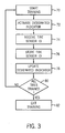
- FIG. 3 an exemplary method of facilitating training of a tire pressure monitoring system on a vehicle is described. It is understood that one or more of the steps in this exemplary method may be eliminated or rearranged in various embodiments.
- training includes storing an identifier for a designated tire location in memory.
- training can include a method performed by a user, a process performed by the control circuit, a method including recording identifiers for all tires on a vehicle, or any other method to recognize tires on a vehicle.
- control circuit 38 identifies whether the user has requested system 22 to enter a training mode to begin training. For example, the user may hold down one, two, or more devices of operator input device 62 for a predetermined time period (e.g., 10 seconds, 20 seconds, etc.) to place control circuit 38 in a training mode, or the user may actuate a separate input device coupled to control circuit 38 (FIG. 2) to place system 22 in the training mode.
- a predetermined time period e.g. 10 seconds, 20 seconds, etc.
- control circuit 38 will initialize training for a tire location.
- a first tire location can be chosen from the tire locations in a logical order such as right-front, left-front, left-rear, right-rear.
- Control circuit 38 is configured to send a control message through vehicle communication bus interface 36 to cause an external indicator in proximity with the first tire location to actuate.
- control circuit 38 can send a control signal to cause the right-front turn signal to start flashing.
- the right front headlight, parking light, brake lights (for rear tire locations), etc. can be activated.
- a vehicle horn can be activated to provide an indication to a user.
- the user could be required to train the tire locations in a specified order, and the vehicle horn would be used to indicate a successful training at each location such that the user can progress to the next tire location.
- a single horn beep could be used to indicate a right-front tire location, two horn beeps to indicate a left-front tire location, etc.
- control circuit 38 waits to receive a tire pressure monitor identifier signal from the tire sensor at the designated location at step 74 .
- this signal can be sent as a result of a manual training operation by the user.
- the user goes to the tire location indicated by the external indicator and holds an actuation device in close proximity to the tire at the designated location.
- the actuation device causes the tire sensor to begin transmitting a tire pressure monitor identifier signal.
- the actuation device can include a magnet where the tire sensor includes a magnetic switch, a transponder where the tire sensor includes a receiver, a button or switch coupled to the tire sensor, or any other device or mechanism which will force the tire pressure sensor to begin transmitting.
- control circuit 38 receives the tire sensor identifier signal and retrieves the identifier for the tire for the designated tire location.
- the identifier can be stored in memory 40 in a location associated with the designated tire location.
- the designated location can be incremented to indicate a next tire location.
- a determination can be made in a step 80 whether all the tires have been successfully trained, and if so, the system can end training in step 82 . If all of the tires have not been successfully trained, step 72 can be repeated using the updated designated tire location.
- the external indicator at the first designation location will cease and the external indicator at the second designated location will activate. This will notify the user that the tire at the first designated location was successfully trained and that the user can progress to the second designation location to train the tire at that location.
Landscapes
- Engineering & Computer Science (AREA)
- Mechanical Engineering (AREA)
- Measuring Fluid Pressure (AREA)
- Arrangements For Transmission Of Measured Signals (AREA)
Abstract
Description
- This application claims the benefit of U.S. Provisional Patent Application No. 60/421,356, filed Oct. 25, 2002.
- Vehicles are increasingly incorporating tire pressure monitoring systems. Tire pressure monitoring systems are systems configured to receive messages from sensors associated with each tire on a vehicle. The sensors are configured to detect characteristics of the associated tire such as tire pressure, temperature, wear, etc. The detected characteristics are communicated in the message to the tire pressure monitoring system for analysis and communication to a user.
- In most tire pressure monitoring systems, each sensor is associated with a specific identifier. The specific identifier is included in all messages transmitted from that sensor so that the tire pressure monitoring system can determine the origin of the message. Identification is necessary because messages are often transmitted wirelessly and it is difficult to detect the origin of the message without the specific identifier. The origin is important because messages may be received from sensors other than those associated with tires on the vehicle. For example, a wireless message may be received from a tire sensor on a vehicle parked next to the intended vehicle.
- Accordingly, it may be desirable to configure the tire pressure monitoring system to recognize the identifiers for the tires on the vehicle. Further, the tire pressure monitoring system may be configured to recognize not only the identifiers for tires on the vehicle, but also their location on the vehicle. Accordingly, it may also be desirable to configure the tire pressure monitoring system to recognize a location for each identifier.
- However, configuring the tire pressure monitoring system to recognize the identifiers and/or their location may be a difficult task. In training the system, a user is often required to check a display mounted inside a vehicle to find out which tire is to be trained. The user then forces the sensor for that tire to transmit its identifier by standing next to the tire and actuating the sensor to transmit. The user must then go into the vehicle and check the display to determine whether the training was successful. If not, the user must again return to the sensor to actuate transmission from the sensor again and repeat the process. Further, this process must be repeated for each tire to be trained.
- Accordingly, what is needed is a tire pressure monitoring system configured to provide an external indication to a user indicating which tire is to be trained. What is further needed is such a tire pressure monitoring system configured to provide an external indication whether training was successful. The teachings hereinbelow extend to those embodiments which fall within the scope of the detailed description, regardless of whether they accomplish one or more of the above-mentioned needs.
- According to an exemplary embodiment, a system for facilitating training of a tire pressure monitoring system on a vehicle by providing an indication to the exterior of the vehicle. The system includes a receiver circuit configured to detect a wireless message including a tire sensor identifier, a memory configured to receive and store a number of tire sensor identifiers, at least one external indicator on the vehicle configured to provide an indication to the exterior of the vehicle, and a control circuit configured to provide a control signal to the external indicator on the vehicle to indicate to a user to actuate a tire sensor transmitter.
- According to another exemplary embodiment, a method for indicating a tire to be trained using an external indicator on a vehicle. The method includes indicating a tire to be trained using the external indicator on the vehicle, receiving a wireless message including a tire sensor identifier from a transmitter associated with the tire to be trained, and storing the tire sensor identifier from the tire to be trained.
- According to yet another exemplary embodiment, a system for facilitating training of a tire pressure monitoring system on a vehicle by providing an indication of a tire to be trained to the exterior of the vehicle. The system includes means for providing an external indication on the vehicle to indicate the tire to be trained, means for receiving a wireless message including a tire sensor identifier from a transmitter associated with the tire to be trained, and means for storing the tire sensor identifier from the tire to be trained.
- The invention will become more fully understood from the following detailed description of exemplary embodiments, taken in conjunction with the accompanying drawings, wherein like reference numerals refer to like parts, and in which:
- FIG. 1 is a schematic diagram of a tire monitoring system having a system and method for facilitating recognition of tire sensor identifiers on a vehicle, according to an exemplary embodiment;
- FIG. 2 is a block diagram of the system for facilitating recognition of tire sensor identifiers on the vehicle of FIG. 1, according to an exemplary embodiment; and
- FIG. 3 is a flowchart illustrating a method for facilitating recognition of tire sensor identifiers on the vehicle of FIG. 1.
- Referring first to FIG. 1, a
tire monitoring system 10 is illustrated on avehicle 12.Tire monitoring system 10 is configured to monitor one or more characteristics of one ormore tires monitoring system 10 is a wireless system, which utilizes radio frequency, infrared, or other wireless signal transmission technology to provide tire characteristic data from tires 14-20 to atire monitor 22. Thus,tire monitoring system 10 includes a plurality oftire sensors tire monitor 22. - Tire
monitor 22 includes asingle antenna 32 in this exemplary embodiment for receiving wireless messages from one or more of tire sensors 24-30. In alternative embodiments, multiple antennas may be coupled totire monitor 22 for receiving wireless messages at a plurality of locations onvehicle 12. For example,tire monitor 22 may include four antennas, one disposed in the vicinity of each of tire sensors 24-30. - Tire
monitor 22 is configured to receive wireless messages from one or more of tire sensors 24-30, to monitor the tire characteristic data on the wireless messages, and to selectively display tire characteristic data to an operator ofvehicle 12. For example,tire monitor 22 may receive tire pressure data from tire sensors 24-30 and may monitor the tire pressure data to determine if the tire pressure of any of tires 14-20 is greater than or less than predetermined maximum and/or minimum thresholds and may provide a display and associated alarm (visible, audible, etc.) to the operator ofvehicle 12 in the vehicle interior. The alarm indicates to the operator that maintenance of the tire causing the alarm may be needed. - Each of tire sensors 24-30 is configured to transmit tire sensor identifier signals (IDs) or tire identification data, which may be any type of message uniquely identifying the tire. For example, a tire identification of “000f”, in hexadecimal representation, may indicate a first tire, while a tire identification of “01af” may identify a second tire. Tire
monitor 22 may be configured to receive the tire identification data on the wireless message and to identify a location of the tire onvehicle 12, to provide more meaningful tire data to the operator ofvehicle 12. For example,tire monitor 22 may associate a tire identification of “000f” with the vehicle position of “left front”, and display the tire pressure data associated with tire “000f” along with a display indicating that the tire is the left front tire, such as, “LF 28”. In this manner, useful information can be provided to the operator ofvehicle 12 to determine alarm conditions, such as, “LF LOW”, “RR LOW”, etc. -
Vehicle 12 further includesexternal indicators 37. (Shown in FIG. 2)External indicators 37 can include turn signals, head lights, break lights, the vehicle horn, or any other system coupled to a vehicle or vehicle exterior element (e.g., bumper, side panel, hood, etc.) that can be used to provide a signal or indication to a person standing outside a vehicle.External indicators 37 can be controlled by sending a control signal over the vehicle communication bus to actuate the external indicator. For example, a control signal can be sent over a vehicle communication bus to flash the right-front turn signal. According to an alternative embodiment, external indicators can receive control signals without being connected or controlled through the vehicle communication bus. - Referring now to FIG. 2, a block diagram of
tire monitoring system 22 is illustrated according to an exemplary embodiment.Tire monitoring system 22 includes areceiver circuit 34, a vehiclecommunication bus interface 36, acontrol circuit 38, and amemory 40.Circuits interface 36, andmemory 40 are illustrated in block form to indicate that these elements are functional units which may be embodied in hardware circuitry, software, or other processing elements. For example,circuits interface 36 andmemory 40 may be disposed on one or more integrated circuits, and may be part of a system-on-chip (SOC), and may further include programmable logic, microprocessors, microcontrollers, or other control circuitry. Furthermore,memory 40 may include volatile memory portions and non-volatile memory portions, and may include random access memory, read-only memory, and/or other memory types. -
Receiver circuit 34 is configured to receive wireless messages viaantenna 32 from tire sensors 24-30. Tire sensors 24-30 are configured to transmit blocks of wireless messages, each block including eight identical frames of data, in this exemplary embodiment. Due to interference, multipath, and other sources of error, tire sensors 24-30 send duplicative data in each of the frames of each block. Tire sensors 24-30 are configured to transmit blocks of data periodically, wherein the rate of transmissions is greater when the vehicle is in motion than when the vehicle is idle. For example, when the vehicle is in motion, a block of data may be sent from each of tire sensors 24-30 at a rate of one transmission per 60 seconds, and whenvehicle 12 is idle, tire sensors 24-30 are each configured to send a block of data at a rate of one transmission per 60 minutes.Receiver circuit 34 may include amplifying circuitry, filtering circuitry, buffering circuitry, demodulating circuitry, and/or other circuit elements necessary to receive wireless messages from tire sensors 24-30 viaantenna 32. -
Control circuit 38 is coupled toreceiver circuit 34 and is configured to store the transmitter IDs provided byreceiver circuit 34 inmemory 40.Control circuit 38 is configured to control the various portions ofsystem 22, to store data in memory, to operate preprogrammed functionality, etc.Control circuit 38 may include various types of control circuitry, digital and/or analog, and may include a microprocessor, microcontroller, application-specific integrated circuit (ASIC), or other circuitry configured to perform various input/output, control, analysis, and other functions to be described herein. -
Control circuit 38 is coupled to anoperator input device 62 which includes one or more push button switches but may alternatively include other user input devices, such as, switches, knobs, dials, etc., or even a voice-actuated input control circuit configured to receive voice signals from a vehicle occupant and to provide such signals to controlcircuit 38 for control ofsystem 22. -
Control circuit 38 is further coupled to adisplay 60 which includes a liquid crystal display (LCD).Display 60 may alternatively include other display elements, such as a light-emitting diodes (LED), a vacuum florescent display (VFD), or other display elements. -
Control circuit 38 is further coupled to a vehiclecommunication bus interface 36 configured to allowcontrol circuit 38 to transmit control signals over the vehicle communication bus to external indicators on a vehicle. The vehicle communication bus can be any type of communication bus, such as, a bus following the J1850 communication protocol, a serial or parallel data bus, a digital or analog data bus, etc. According to an alternative embodiment,control circuit 38 can be coupled toexternal indicators 37 on a vehicle without using the vehicle communication bus or wirelessly (e.g., via radio frequency, infrared, etc.). - Referring to FIG. 3, an exemplary method of facilitating training of a tire pressure monitoring system on a vehicle is described. It is understood that one or more of the steps in this exemplary method may be eliminated or rearranged in various embodiments.
- According to this exemplary embodiment, training includes storing an identifier for a designated tire location in memory. According to alternative embodiments, training can include a method performed by a user, a process performed by the control circuit, a method including recording identifiers for all tires on a vehicle, or any other method to recognize tires on a vehicle.
- At
step 70,control circuit 38 identifies whether the user has requestedsystem 22 to enter a training mode to begin training. For example, the user may hold down one, two, or more devices ofoperator input device 62 for a predetermined time period (e.g., 10 seconds, 20 seconds, etc.) to placecontrol circuit 38 in a training mode, or the user may actuate a separate input device coupled to control circuit 38 (FIG. 2) to placesystem 22 in the training mode. - Once training has begun, at
step 72,control circuit 38 will initialize training for a tire location. A first tire location can be chosen from the tire locations in a logical order such as right-front, left-front, left-rear, right-rear.Control circuit 38 is configured to send a control message through vehiclecommunication bus interface 36 to cause an external indicator in proximity with the first tire location to actuate. For example, where the right-front is the first location,control circuit 38 can send a control signal to cause the right-front turn signal to start flashing. According to alternative embodiments, the right front headlight, parking light, brake lights (for rear tire locations), etc. can be activated. - According to yet another embodiment, a vehicle horn can be activated to provide an indication to a user. According to this embodiment, the user could be required to train the tire locations in a specified order, and the vehicle horn would be used to indicate a successful training at each location such that the user can progress to the next tire location. According to an alternative embodiment, a single horn beep could be used to indicate a right-front tire location, two horn beeps to indicate a left-front tire location, etc.
- Once the external indicator has been activated,
control circuit 38 waits to receive a tire pressure monitor identifier signal from the tire sensor at the designated location atstep 74. According to an exemplary embodiment, this signal can be sent as a result of a manual training operation by the user. In this embodiment, the user goes to the tire location indicated by the external indicator and holds an actuation device in close proximity to the tire at the designated location. The actuation device causes the tire sensor to begin transmitting a tire pressure monitor identifier signal. The actuation device can include a magnet where the tire sensor includes a magnetic switch, a transponder where the tire sensor includes a receiver, a button or switch coupled to the tire sensor, or any other device or mechanism which will force the tire pressure sensor to begin transmitting. - At
step 76,control circuit 38 receives the tire sensor identifier signal and retrieves the identifier for the tire for the designated tire location. The identifier can be stored inmemory 40 in a location associated with the designated tire location. - At
step 78, after correctly receiving and storing the tire sensor identifier signal, the designated location can be incremented to indicate a next tire location. Following the update of the designated location, a determination can be made in astep 80 whether all the tires have been successfully trained, and if so, the system can end training instep 82. If all of the tires have not been successfully trained, step 72 can be repeated using the updated designated tire location. The external indicator at the first designation location will cease and the external indicator at the second designated location will activate. This will notify the user that the tire at the first designated location was successfully trained and that the user can progress to the second designation location to train the tire at that location. - Flashing an external indicator allows
control circuit 38 to indicate to a user which tire needs to be trained and also when the tire has been successfully trained. Providing feedback to a user externally provides the benefit of not requiring that the user enter the vehicle toview display 60 in between each tire training. Accordingly, as each tire is trained, the user can walk directly to the next tire in the sequence as directed by the external indicators. By directing the user to the appropriate tire by using the external indicator, the tire training process is less confusing, more simple, quicker, and less frustrating. - While the exemplary embodiments illustrated in the FIGURES and described above are presently preferred, it should be understood that these embodiments are offered by way of example only. For example, various techniques for comparing detected tire sensor identifier signals with stored identifiers may be used. Further, the teachings herein may be applied to various types of vehicles, including cars, trucks, all-terrain vehicles, construction vehicles, etc. Accordingly, the present invention is not limited to a particular embodiment, but extends to various modifications that nevertheless fall within the scope of the appended claim.
Claims (23)
Priority Applications (1)
| Application Number | Priority Date | Filing Date | Title |
|---|---|---|---|
| US10/693,139 US7084751B2 (en) | 2002-10-25 | 2003-10-24 | System and method of facilitating training of a tire pressure monitoring system on a vehicle |
Applications Claiming Priority (2)
| Application Number | Priority Date | Filing Date | Title |
|---|---|---|---|
| US42135602P | 2002-10-25 | 2002-10-25 | |
| US10/693,139 US7084751B2 (en) | 2002-10-25 | 2003-10-24 | System and method of facilitating training of a tire pressure monitoring system on a vehicle |
Publications (2)
| Publication Number | Publication Date |
|---|---|
| US20040140887A1 true US20040140887A1 (en) | 2004-07-22 |
| US7084751B2 US7084751B2 (en) | 2006-08-01 |
Family
ID=32717413
Family Applications (1)
| Application Number | Title | Priority Date | Filing Date |
|---|---|---|---|
| US10/693,139 Expired - Lifetime US7084751B2 (en) | 2002-10-25 | 2003-10-24 | System and method of facilitating training of a tire pressure monitoring system on a vehicle |
Country Status (1)
| Country | Link |
|---|---|
| US (1) | US7084751B2 (en) |
Cited By (4)
| Publication number | Priority date | Publication date | Assignee | Title |
|---|---|---|---|---|
| US20050071057A1 (en) * | 2003-09-26 | 2005-03-31 | Lite-On Automotive Corp. | Tire monitoring system with a wireless setting capability |
| US20140266661A1 (en) * | 2013-03-15 | 2014-09-18 | Continental Automotive Systems, Inc. | Methods, systems and devices for integration of tire pressure monitoring sensors with a tire pressure monitoring system |
| WO2014160186A1 (en) | 2013-03-13 | 2014-10-02 | Bosch Automotive Service Solutions Llc | Vehicle measurement apparatus having a system-on-a-chip device, a sensor and a wireless adapter |
| WO2015102955A1 (en) * | 2013-12-31 | 2015-07-09 | Continental Automotive Systems, Inc. | A method, apparatus and system for indicating the location of a tire in an abnormal condition using at least one vehicle turn signal |
Families Citing this family (14)
| Publication number | Priority date | Publication date | Assignee | Title |
|---|---|---|---|---|
| US7518495B2 (en) * | 2003-11-18 | 2009-04-14 | Lear Corporation | Universal tire pressure monitor |
| CN101687447B (en) | 2007-07-03 | 2015-02-11 | 欧陆汽车系统美国有限公司 | Universal tire pressure monitoring sensor |
| US8751092B2 (en) | 2011-01-13 | 2014-06-10 | Continental Automotive Systems, Inc. | Protocol protection |
| RU2572990C2 (en) | 2011-08-09 | 2016-01-20 | Континенталь Отомоутив Системз, Инк. | Localization process activation device and method for tire pressure monitoring unit |
| US9676238B2 (en) | 2011-08-09 | 2017-06-13 | Continental Automotive Systems, Inc. | Tire pressure monitor system apparatus and method |
| CN103826879B (en) | 2011-08-09 | 2017-10-10 | 大陆汽车系统公司 | Apparatus and method for transmitting tire pressure signal |
| US8742914B2 (en) | 2011-08-09 | 2014-06-03 | Continental Automotive Systems, Inc. | Tire pressure monitoring apparatus and method |
| KR101599780B1 (en) | 2011-08-09 | 2016-03-04 | 컨티넨탈 오토모티브 시스템즈 인코포레이티드 | Protocol misinterpretation avoidance apparatus and method for a tire pressure monitoring system |
| US9076275B2 (en) | 2013-03-13 | 2015-07-07 | Bosch Automotive Service Solutions Inc. | Vehicle measurement apparatus having a system-on-a-chip device and a sensor |
| US9446636B2 (en) | 2014-02-26 | 2016-09-20 | Continental Automotive Systems, Inc. | Pressure check tool and method of operating the same |
| TWI593570B (en) * | 2014-05-30 | 2017-08-01 | Method to set the position of the tire pressure sensor | |
| US9517664B2 (en) | 2015-02-20 | 2016-12-13 | Continental Automotive Systems, Inc. | RF transmission method and apparatus in a tire pressure monitoring system |
| DE102016213290A1 (en) | 2015-08-03 | 2017-02-09 | Continental Automotive Systems, Inc. | Apparatus, system and method for configuring a tire information sensor with a transmission protocol based on vehicle trigger characteristics |
| CN108248301A (en) * | 2017-12-29 | 2018-07-06 | 南京泰普晟软件有限公司 | Tire lifecycle management system |
Citations (6)
| Publication number | Priority date | Publication date | Assignee | Title |
|---|---|---|---|---|
| US6243007B1 (en) * | 1999-12-01 | 2001-06-05 | Mclaughlin John T. | Tire condition monitoring system |
| US20030030553A1 (en) * | 2001-08-06 | 2003-02-13 | Kenneth Schofield | Self training tire pressure monitoring system |
| US20030080860A1 (en) * | 2001-10-29 | 2003-05-01 | Stewart William David | Determination of wheel sensor position using radio frequency detectors in an automotive remote tire monitor system |
| US6612165B2 (en) * | 2002-02-04 | 2003-09-02 | Trw Inc. | Tire pressure monitoring system with pressure gauge operating mode for indicating when air pressure within a tire is within a predetermined pressure range |
| US20030234723A1 (en) * | 2002-06-24 | 2003-12-25 | Lite-On Automotive Corp. | Code learning method for tire monitoring device |
| US20040041698A1 (en) * | 2002-08-30 | 2004-03-04 | Lite-On Automotive Corp. | Code learning device for tire pressure monitor |
Family Cites Families (2)
| Publication number | Priority date | Publication date | Assignee | Title |
|---|---|---|---|---|
| GB2344232B (en) | 1998-10-16 | 2003-08-20 | Otter Controls Ltd | A tyre condition monitoring system |
| DE10014076B4 (en) | 2000-03-22 | 2004-12-09 | Nolex Ag | Tire pressure display device |
-
2003
- 2003-10-24 US US10/693,139 patent/US7084751B2/en not_active Expired - Lifetime
Patent Citations (6)
| Publication number | Priority date | Publication date | Assignee | Title |
|---|---|---|---|---|
| US6243007B1 (en) * | 1999-12-01 | 2001-06-05 | Mclaughlin John T. | Tire condition monitoring system |
| US20030030553A1 (en) * | 2001-08-06 | 2003-02-13 | Kenneth Schofield | Self training tire pressure monitoring system |
| US20030080860A1 (en) * | 2001-10-29 | 2003-05-01 | Stewart William David | Determination of wheel sensor position using radio frequency detectors in an automotive remote tire monitor system |
| US6612165B2 (en) * | 2002-02-04 | 2003-09-02 | Trw Inc. | Tire pressure monitoring system with pressure gauge operating mode for indicating when air pressure within a tire is within a predetermined pressure range |
| US20030234723A1 (en) * | 2002-06-24 | 2003-12-25 | Lite-On Automotive Corp. | Code learning method for tire monitoring device |
| US20040041698A1 (en) * | 2002-08-30 | 2004-03-04 | Lite-On Automotive Corp. | Code learning device for tire pressure monitor |
Cited By (7)
| Publication number | Priority date | Publication date | Assignee | Title |
|---|---|---|---|---|
| US20050071057A1 (en) * | 2003-09-26 | 2005-03-31 | Lite-On Automotive Corp. | Tire monitoring system with a wireless setting capability |
| US7039508B2 (en) * | 2003-09-26 | 2006-05-02 | Lite-On Automotive Corp. | Tire monitoring system with a wireless setting capability |
| WO2014160186A1 (en) | 2013-03-13 | 2014-10-02 | Bosch Automotive Service Solutions Llc | Vehicle measurement apparatus having a system-on-a-chip device, a sensor and a wireless adapter |
| EP2973487A4 (en) * | 2013-03-13 | 2017-01-11 | Bosch Automotive Service Solutions Inc. | Vehicle measurement apparatus having a system-on-a-chip device, a sensor and a wireless adapter |
| US20140266661A1 (en) * | 2013-03-15 | 2014-09-18 | Continental Automotive Systems, Inc. | Methods, systems and devices for integration of tire pressure monitoring sensors with a tire pressure monitoring system |
| US9120357B2 (en) * | 2013-03-15 | 2015-09-01 | Continental Automotive Systems, Inc. | Methods, systems and devices for integration of tire pressure monitoring sensors with a tire pressure monitoring system |
| WO2015102955A1 (en) * | 2013-12-31 | 2015-07-09 | Continental Automotive Systems, Inc. | A method, apparatus and system for indicating the location of a tire in an abnormal condition using at least one vehicle turn signal |
Also Published As
| Publication number | Publication date |
|---|---|
| US7084751B2 (en) | 2006-08-01 |
Similar Documents
| Publication | Publication Date | Title |
|---|---|---|
| US7084751B2 (en) | System and method of facilitating training of a tire pressure monitoring system on a vehicle | |
| US6441727B1 (en) | Arrangement and method of vehicle tire identification | |
| US7224269B2 (en) | Method and system for resetting tire pressure monitoring system for an automotive vehicle | |
| US6788193B2 (en) | System and method for tire pressure monitoring providing automatic tire location recognition | |
| US6838985B2 (en) | System and method for remote tire pressure monitoring with low frequency initiation | |
| EP0982159B1 (en) | Tire air pressure monitoring system | |
| US6246317B1 (en) | Target pressure learn strategy for vehicular tire pressure systems | |
| CN101746232B (en) | Method and system for associating a tire pressure sensor to a wheel location in an intitiator based tire pressure monitoring system | |
| CA2341790C (en) | Tire pressure display device | |
| EP1946945B1 (en) | Vehicle monitoring system | |
| US7705714B2 (en) | Wheel position detecting device that performs dedicated local communication for each wheel and tire air pressure detecting device including the same | |
| US7358852B2 (en) | Tire pressure monitoring sensor diagnosis via vehicle antitheft and entry system | |
| WO2003016079A1 (en) | Tire monitor compatible with multiple data protocols | |
| EP0671289A1 (en) | Vehicle remote actuating system | |
| US6668636B2 (en) | System and method for tire pressure monitoring including tire location recognition | |
| US9387732B1 (en) | Tire pressure monitoring system (TPMS) activation method | |
| MX2007014019A (en) | Determination of wheel sensor position using a single radio frequency detector in an automotive remote tire monitor system. | |
| US6691567B2 (en) | System and method for tire pressure monitoring including automatic tire location recognition | |
| US20030107481A1 (en) | Tire condition monitoring apparatus and method | |
| JP2010274749A (en) | Tire pressure monitoring system and air pressure monitoring unit | |
| JP2003242585A (en) | Tire state monitoring device | |
| US20030164759A1 (en) | System and method for tire pressure monitoring with optimal tire pressure indication during tire pressure adjustment | |
| US6725712B1 (en) | System and method for tire pressure monitoring with automatic tire location recognition | |
| JP2004216930A (en) | Sensor identification registration method of tire air pressure monitoring device | |
| US8026803B2 (en) | Apparatus and process for monitoring a vehicle condition |
Legal Events
| Date | Code | Title | Description |
|---|---|---|---|
| AS | Assignment |
Owner name: JOHNSON CONTROLS TECHNOLOGY COMPANY, MICHIGAN Free format text: ASSIGNMENT OF ASSIGNORS INTEREST;ASSIGNOR:KLAMER, DOUGLAS W.;REEL/FRAME:015162/0230 Effective date: 20040219 |
|
| STCF | Information on status: patent grant |
Free format text: PATENTED CASE |
|
| FEPP | Fee payment procedure |
Free format text: PAYOR NUMBER ASSIGNED (ORIGINAL EVENT CODE: ASPN); ENTITY STATUS OF PATENT OWNER: LARGE ENTITY |
|
| FPAY | Fee payment |
Year of fee payment: 4 |
|
| FPAY | Fee payment |
Year of fee payment: 8 |
|
| AS | Assignment |
Owner name: GENTEX CORPORATION, MICHIGAN Free format text: ASSIGNMENT OF ASSIGNORS INTEREST;ASSIGNOR:GENTEX CORPORATION;REEL/FRAME:032471/0695 Effective date: 20130927 |
|
| AS | Assignment |
Owner name: GENTEX CORPORATION, MICHIGAN Free format text: CORRECTIVE ASSIGNMENT TO CORRECT THE PATENT # 5703941 IS INCORRECT AND SHOULD BE 6703941. PATENT # 6330569 IS INCORRECT AND SHOULD BE 8330569. PREVIOUSLY RECORDED ON REEL 032471 FRAME 0695. ASSIGNOR(S) HEREBY CONFIRMS THE ASSIGNMENT OF ASSIGNORS INTEREST;ASSIGNOR:GENTEX CORPORATION;REEL/FRAME:032514/0564 Effective date: 20130927 |
|
| AS | Assignment |
Owner name: GENTEX CORPORATION, MICHIGAN Free format text: CORRECTIVE ASSIGNMENT TO CORRECT THE ASSIGNOR, SHOULD BE JOHNSON CONTROLS TECHNOLOGY COMPANY. ADDITIONAL CORRECTIVE ASSIGNMENT RECORDED @ 032514/0564. PREVIOUSLY RECORDED ON REEL 032471 FRAME 0695. ASSIGNOR(S) HEREBY CONFIRMS THE ASSIGNMENT OF ASSIGNORS INTEREST;ASSIGNOR:JOHNSON CONTROLS TECHNOLOGY COMPANY;REEL/FRAME:032621/0757 Effective date: 20130927 |
|
| AS | Assignment |
Owner name: GENTEX CORPORATION, MICHIGAN Free format text: CORRECTIVE ASSIGNMENT TO CORRECT THE ASSIGNOR, IT SHOULD BE JOHNSON CONTROLS TECHNOLOGY COMPANY. PREVIOUSLY RECORDED ON REEL 032514 FRAME 0564. ASSIGNOR(S) HEREBY CONFIRMS THE ASSIGNMENT OF ASSIGNORS INTEREST;ASSIGNOR:JOHNSON CONTROLS TECHNOLOGY COMPANY;REEL/FRAME:032664/0688 Effective date: 20130927 |
|
| MAFP | Maintenance fee payment |
Free format text: PAYMENT OF MAINTENANCE FEE, 12TH YEAR, LARGE ENTITY (ORIGINAL EVENT CODE: M1553) Year of fee payment: 12 |