US20040103864A1 - Automatic priming system - Google Patents
Automatic priming system Download PDFInfo
- Publication number
- US20040103864A1 US20040103864A1 US10/658,063 US65806303A US2004103864A1 US 20040103864 A1 US20040103864 A1 US 20040103864A1 US 65806303 A US65806303 A US 65806303A US 2004103864 A1 US2004103864 A1 US 2004103864A1
- Authority
- US
- United States
- Prior art keywords
- engine
- chamber
- crankcase
- carburetor
- pressure pulses
- Prior art date
- Legal status (The legal status is an assumption and is not a legal conclusion. Google has not performed a legal analysis and makes no representation as to the accuracy of the status listed.)
- Granted
Links
- 230000037452 priming Effects 0.000 title claims abstract description 76
- 238000004891 communication Methods 0.000 claims abstract description 43
- 239000012530 fluid Substances 0.000 claims abstract description 40
- 238000002485 combustion reaction Methods 0.000 claims abstract description 23
- 239000000446 fuel Substances 0.000 claims description 92
- 238000000034 method Methods 0.000 claims description 5
- 238000013022 venting Methods 0.000 claims description 5
- 230000000903 blocking effect Effects 0.000 claims 1
- 230000002401 inhibitory effect Effects 0.000 claims 1
- 239000003921 oil Substances 0.000 description 26
- 239000000203 mixture Substances 0.000 description 12
- 239000007789 gas Substances 0.000 description 8
- 230000008859 change Effects 0.000 description 6
- 230000001133 acceleration Effects 0.000 description 3
- 230000008901 benefit Effects 0.000 description 2
- 230000006835 compression Effects 0.000 description 2
- 238000007906 compression Methods 0.000 description 2
- 230000007423 decrease Effects 0.000 description 2
- 238000013461 design Methods 0.000 description 2
- 230000000694 effects Effects 0.000 description 2
- 239000002828 fuel tank Substances 0.000 description 2
- 230000014509 gene expression Effects 0.000 description 2
- 239000007788 liquid Substances 0.000 description 2
- WANLLPADDCXPGO-WMKJBNATSA-N (6r,9s,12s)-3-[(2s)-butan-2-yl]-6-[(4-methoxyphenyl)methyl]-9-[6-(oxiran-2-yl)-6-oxohexyl]-1,4,7,10-tetrazabicyclo[10.4.0]hexadecane-2,5,8,11-tetrone Chemical compound C([C@@H]1C(=O)NC(C(N2CCCC[C@H]2C(=O)N[C@@H](CCCCCC(=O)C2OC2)C(=O)N1)=O)[C@@H](C)CC)C1=CC=C(OC)C=C1 WANLLPADDCXPGO-WMKJBNATSA-N 0.000 description 1
- WANLLPADDCXPGO-UHFFFAOYSA-N Cyl-2 Natural products N1C(=O)C(CCCCCC(=O)C2OC2)NC(=O)C2CCCCN2C(=O)C(C(C)CC)NC(=O)C1CC1=CC=C(OC)C=C1 WANLLPADDCXPGO-UHFFFAOYSA-N 0.000 description 1
- 108010063406 Cyl-2 Proteins 0.000 description 1
- 230000006978 adaptation Effects 0.000 description 1
- 238000013459 approach Methods 0.000 description 1
- 230000001419 dependent effect Effects 0.000 description 1
- 238000009795 derivation Methods 0.000 description 1
- 230000006872 improvement Effects 0.000 description 1
- 230000010354 integration Effects 0.000 description 1
- 238000012804 iterative process Methods 0.000 description 1
- 230000001050 lubricating effect Effects 0.000 description 1
- 239000010687 lubricating oil Substances 0.000 description 1
- 238000005461 lubrication Methods 0.000 description 1
- 239000000463 material Substances 0.000 description 1
- 239000003595 mist Substances 0.000 description 1
- 230000000737 periodic effect Effects 0.000 description 1
- 238000004064 recycling Methods 0.000 description 1
- 238000012546 transfer Methods 0.000 description 1
- 230000001052 transient effect Effects 0.000 description 1
- 238000011144 upstream manufacturing Methods 0.000 description 1
- 210000000707 wrist Anatomy 0.000 description 1
Images


Classifications
-
- F—MECHANICAL ENGINEERING; LIGHTING; HEATING; WEAPONS; BLASTING
- F02—COMBUSTION ENGINES; HOT-GAS OR COMBUSTION-PRODUCT ENGINE PLANTS
- F02M—SUPPLYING COMBUSTION ENGINES IN GENERAL WITH COMBUSTIBLE MIXTURES OR CONSTITUENTS THEREOF
- F02M1/00—Carburettors with means for facilitating engine's starting or its idling below operational temperatures
- F02M1/16—Other means for enriching fuel-air mixture during starting; Priming cups; using different fuels for starting and normal operation
Definitions
- the present invention relates to small internal combustion engines of the type used with lawn mowers, lawn and garden tractors, snow throwers and other working implements, or with small sport vehicles. Particularly, the present invention relates to a priming system to aid in starting such engines.
- Small internal combustion engines typically include a carburetor which mixes liquid fuel with atmospheric air drawn through the carburetor to provide an air/fuel combustion mixture to the engine.
- a carburetor which mixes liquid fuel with atmospheric air drawn through the carburetor to provide an air/fuel combustion mixture to the engine.
- One type of carburetor commonly used in small engines includes a throat with a venturi through which air is drawn, and into which fuel is drawn for mixing with the intake air, as well as a fuel bowl disposed beneath the throat in which a quantity of liquid fuel is stored.
- a float valve in the fuel bowl meters a supply of fuel thereinto from a main fuel tank as necessary as the fuel in the fuel bowl is consumed.
- such carburetors typically include a manually operable priming feature, such as a priming bulb which is pressed by an operator to pressurize the air space above the fuel in the fuel bowl, thereby forcing a quantity of priming fuel from the fuel bowl into the carburetor throat for mixing with the intake air which is drawn into the carburetor.
- the priming fuel is in excess of the amount of fuel which is normally supplied for mixing with the intake air to form the combustion mixture, such that a rich air/fuel mixture is initially supplied to the engine to aid in engine starting. After the engine starts, the priming fuel is consumed, and mixing of the air/fuel mixture is thereafter controlled by the fuel metering system of the carburetor during running of the engine.
- the foregoing priming feature for carburetors requires an operator to manually press the priming bulb to prime the engine. If the operator does not press the bulb enough times, or if the operator fails to press the priming bulb altogether, pressure will not be built up within the fuel bowl of the carburetor to the extent necessary to supply priming fuel to aid in engine starting. Therefore, difficulty may be encountered in starting the engine. Conversely, if the priming bulb is pressed by an operator too many times, an undesirably large amount of priming fuel may be supplied, which could flood the engine.
- carburetors for small engines also include a choke feature, such as a choke valve, which is manually actuated by the operator during engine starting to further enrich the air/fuel mixture initially supplied to tile engine.
- a choke feature such as a choke valve
- the carburetor will continue to supply an enriched air/fuel mixture to the engine after the engine has started, which could flood the engine. Therefore, the operator must remember to deactivate the choke feature after the engine begins to run in order to prevent the engine from flooding.
- the present invention provides an automatic priming system for internal combustion engines, which is operable at engine cranking speeds, and which is automatically disabled at engine running speeds.
- the automatic priming system is driven by pressure fluctuations within the engine crankcase which are caused by reciprocation of the piston.
- fluid communication between the engine crankcase air space and a chamber is substantially equalized, such that positive pressure pulses from the crankcase pass from the chamber through a check valve to the carburetor for priming.
- communication between the crankcase and the chamber is restricted such that the pressure within the chamber is below atmospheric, positive pressure pulses are not present within the chamber, and the priming function is automatically disabled.
- a restrictor is provided between the crankcase and the chamber.
- the pressure fluctuations within the crankcase do not occur rapidly enough for the restrictor to restrict fluid communication of the pressure fluctuations between the crankcase and the chamber, such that the pressures in the crankcase and the chamber may substantially equalize.
- positive pressure pulses are supplied to the carburetor from the chamber through the check valve for priming.
- the pressure fluctuations within the crankcase occur very rapidly, and the restrictor restricts full communication thereof to the chamber such that the pressure in the chamber does not exceed atmospheric pressure. Therefore, no positive pressure pulses are supplied to the carburetor at engine running speeds, and the priming function is disabled.
- the automatic priming system is driven by pressure pulses from the engine crankcase which are generated by reciprocation of the piston, as controlled by the restrictor, chamber, and check valve, the automatic priming system does not require manual priming of the carburetor or manual operation of a choke feature of the carburetor to prime the carburetor for engine starting and to disable the priming function when the engine reaches running speed.
- the present automatic priming system may include a low oil shutdown feature which disables running of the engine when the oil level in the crankcase drops below a level in which damage to the engine could potentially occur.
- a low oil shutdown feature which disables running of the engine when the oil level in the crankcase drops below a level in which damage to the engine could potentially occur.
- the present invention provides an internal combustion engine, including an engine housing including a crankcase and a cylinder; a crankshaft, connecting rod, and piston assembly disposed within the engine housing, the piston reciprocable within the cylinder to generate positive and negative pressure pulses within the crankcase during cranking and running speeds of the engine; a carburetor attached to the engine housing; and a priming system, including a chamber in fluid communication with the crankcase through a restrictor, the chamber also in fluid communication with the carburetor through a one-way valve permitting fluid flow from the chamber to the carburetor, the restrictor dimensioned to allow substantially uninhibited communication of pressure pulses between the crankcase and the chamber at engine cranking speeds and to dampen communication of pressure pulses between the crankcase and the chamber at engine running speeds; whereby at engine cranking speeds, positive pressure pulses may pass from the chamber to the carburetor through the one-way valve, and at engine running speeds, the positive pressure pulses are substantially absent within the chamber.
- the present invention provides an internal combustion engine, including an engine housing including a crankcase and a cylinder; a crankshaft, connecting rod, and piston assembly disposed within the engine housing, the piston reciprocable within the cylinder to generate positive and negative pressure pulses within the crankcase during cranking and running speeds of the engine; a carburetor attached to the engine housing; and a priming system, including a chamber in fluid communication with the crankcase, the chamber also in fluid communication with the carburetor; a check valve disposed between the chamber and the carburetor, the check valve permitting fluid flow from the chamber to the carburetor and preventing fluid flow from the carburetor to the chamber; and means for allowing substantial pressure equalization between the crankcase and the chamber at engine cranking speeds such that positive pressure pulses may pass from the chamber through the check valve to the carburetor for priming, and for preventing substantial pressure equalization between the crankcase and the chamber at engine running speeds such that positive pressure pulses are not present within the chamber.
- the present invention provides a method of operating an internal combustion engine, including the steps of cranking a crankshaft, connecting rod, and piston assembly of the engine to reciprocate the piston within a cylinder and to generate positive and negative pressure pulses within a crankcase of the engine; allowing substantially uninhibited fluid communication during cranking between the crankcase and a chamber in fluid communication with the crankcase; during cranking, conducting positive pressure pulses from the chamber to the carburetor for priming while preventing passage of negative pressure pulses from the chamber to the carburetor; starting the engine; and subsequent to starting the engine, preventing substantially the passage of positive pressure pulses from the chamber to the carburetor.
- FIG. 1 is a schematic representation of an exemplary automatic priming system according to the present invention
- FIG. 2 is a first side view of an internal combustion engine including an automatic priming system according to an alternative embodiment
- FIG. 3 is a second side view of the engine of FIG. 2, showing the carburetor and a portion of the crankcase in section;
- FIG. 4 is a top view of the engine of FIGS. 2 and 3, showing the crankcase, cylinder block, and carburetor in section;
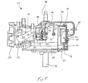
- FIG. 5 is a side view of an internal combustion engine including an automatic priming system according to a further alternative embodiment, showing the carburetor and a portion of the crankcase in section, the engine further including a low oil shutdown feature;
- FIG. 6 is a graphic representation of fuel bowl pressure and chamber pressure vs. time at engine cranking speeds
- FIG. 7 is a graphic representation of crankcase pressure, chamber pressure, and fuel bowl pressure vs. crank angle at engine cranking speeds;
- FIG. 8 is a graphic representation of fuel bowl pressure and chamber pressure vs. time at engine accelerating speeds immediately after engine starting;
- FIG. 9 is a graphic representation of fuel bowl pressure and chamber pressure vs. time at engine running speeds.
- FIG. 10 is a graphic representation of crankcase pressure, chamber pressure, and fuel bowl pressure vs. crank angle at engine running speeds.
- automatic priming system 20 is schematically shown in connection with engine 22 , and is shown in greater detail according to alternate embodiments in FIGS. 2 - 5 .
- Engine 22 may be a small, single or twin cylinder internal combustion engine of the type used in lawn mowers, lawn and garden tractors, snow throwers, generators, other working implements, or in small sport vehicles. Further, engine 22 may have a valve train of an overhead cam (“OHC”), overhead valve (“OHV”), or side valve/L-head type.
- Engine 22 includes crankcase 24 , cylinder block 26 attached to crankcase 24 , and cylinder head 28 attached to cylinder block 26 .
- crankcase 24 and cylinder block 26 may be integrally formed with one another, or cylinder block 26 and cylinder head 28 may be integrally formed with one another.
- Piston 30 is slidably received within cylinder 32 in cylinder block 26 , and combustion chamber 34 is defined between piston 30 and cylinder head 28 .
- Crankshaft 36 is rotatably supported within crankcase 24 via suitable bearings (not shown), and includes eccentric crank pin 38 to which one end of connecting rod 40 is coupled, with the opposite end of connecting rod 40 coupled to wrist pin 42 of piston 30 .
- Crankshaft 36 may be vertically disposed as shown in FIGS. 2 and 3 or alternatively, may be horizontally disposed.
- the crankshaft 36 , connecting rod 40 , and piston 30 assembly may be manually cranked by an operator for starting engine 22 using a recoil motor, for example.
- crankcase 24 At engine cranking speeds and at engine running speeds, reciprocation of piston 30 within cylinder 32 creates pressure fluctuations, or pulses, within crankcase 24 . Specifically, as piston 30 approaches its top dead center (“TDC”) position, a negative, or less than atmospheric, pressure is created within crankcase 24 and, as piston 30 retreats from its TDC position toward its bottom dead center (“BDC”) position, a positive, or greater than atmospheric, pressure is created within crankcase 24 .
- TDC top dead center
- BDC bottom dead center
- blow-by gases typically referred to as “blow-by” gases, and would normally tend to build up within crankcase 24 to create an average positive pressure within crankcase 24 .
- the blow-by gases are typically vented out of crankcase 24 through a one-way breather valve 25 (FIG. 1) connected to crankcase 24 .
- the blow-by gases upon venting from crankcase 24 , may be directed to the intake system of engine 22 for recycling.
- breather valve 25 movement of piston 30 toward its TDC position creates a negative pressure, or partial vacuum condition, within crankcase 24 .
- crankcase 24 is below atmospheric pressure while engine 22 is running, with pressure fluctuations within crankcase 24 occurring in a generally sinusoidal manner as piston 30 reciprocates between its TDC and BDC positions.
- the average of the sinusoidal pressure fluctuations within crankcase 24 is negative, or below atmospheric, the periodic extremes of the pressure pulses, which occur around the BDC position of piston 30 , are positive, i.e., are above atmospheric pressure. As discussed below, these positive pressure pulses are used in automatic priming system 20 for priming.
- automatic priming system 20 generally includes conduit 44 connected to crankcase 24 at its first end 44 a , and connected to carburetor 46 at its opposite end 44 b .
- Carburetor 46 includes main body portion 48 , in which a carburetor throat 47 (FIGS. 3 - 5 ), venturi 49 (FIGS. 3 - 5 ), and throttle valve (not shown) are disposed, and also includes fuel bowl 50 disposed beneath main body portion 48 .
- Carburetor 46 may be of the type disclosed in U.S. Pat. No. 6,152,431, assigned to the assignee of the present invention, the disclosure of which is expressly incorporated herein by reference.
- Main body portion 48 of carburetor 46 is operably connected to intake port 51 or engine 22 via intake manifold 53 , as shown in FIG. 4 for example, to supply an air/fuel mixture for combustion within combustion chamber 34 of engine 22 .
- end 44 b of conduit 44 is connected to carburetor 46 in communication with fuel bowl 50 , and specifically, with air space 52 above a quantity of fuel 54 which is contained within fuel bowl 50 .
- a float valve (not shown) within fuel bowl 50 meters fuel into fuel bowl 50 from a main fuel tank (not shown) of engine 22 .
- the present invention is described herein with respect to a carburetor of the type including a fuel bowl in which priming is carried out by pressurizing an air space above a quantity of fuel in the fuel bowl to thereby force fuel from the fuel bowl into the throat of the carburetor.
- the present invention is more generally applicable for use with other types of carburetors or with separate, designated priming devices which may operate by being pressurized.
- vent conduit 56 may additionally include vent conduit 56 .
- vent conduit 56 fluidly communicates fuel bowl 50 to the atmosphere.
- vent conduit 56 fluidly communicates fuel bowl 50 to the air inlet side of carburetor 46 .
- Vent conduit 56 may include a vent valve 64 , such as a solenoid valve, for example, which is operable in a suitable manner to close during engine starting and to open during engine running, as described further below.
- vent valve 64 may be controlled by the ignition system of engine 22 , or may comprise a thermostatic or bimetallic element responsive to heat produced by engine 22 after engine 22 starts.
- vent valve 64 is alternatively shown as a solenoid valve 65 in fluid communication with conduit 44 via branch conduit 67 , and includes vent port 69 .
- Conduit 44 further includes a dampening or accumulator chamber 58 , shown in FIG. 1 between crankcase 24 and carburetor 46 which, in the exemplary embodiment of FIGS. 6 - 10 , has a volume of approximately 20 cc (20 cm 3 ).
- Conduit 44 additionally includes restrictor 60 , shown in FIG. 1 between crankcase 24 and chamber 58 which, in the exemplary embodiment of FIGS. 6 - 10 , has a diameter of 0.065 inches.
- the size of restrictor 60 may vary depending upon the particular characteristics of each engine, such as crankcase compression ratio and the volume of chamber 58 , as discussed below.
- Restrictor 60 may be a small opening between crankcase 24 and chamber 58 , or a throttling orifice, for example, having a diameter which is smaller than that of conduit 44 , or may be any other suitable device which is operable to restrict fluid movement between crankcase 24 and chamber 58 , as described below.
- a one-way check valve 62 is shown in FIG. 1 disposed in conduit 44 between chamber 58 and carburetor 46 .
- Check valve 62 is configured to permit the fluid flow from chamber 58 to carburetor 46 , and to block fluid flow from carburetor 46 to chamber 58 .
- chamber 58 , restrictor 60 , and check valve 62 have been shown in FIG. 1 as being associated with a common conduit 44 , conduit 44 may be eliminated altogether by, for example, integrating one or more of the foregoing components into a single structural unit which is attached to crankcase 24 , or alternatively, each of the foregoing components may be integrated into crankcase 24 itself.
- FIGS. 2 - 5 the arrangement of the components of priming system 20 is modified as follows.
- Chamber 58 is disposed within crankcase 24 , and includes restrictor 60 in a wall thereof, such that chamber 58 and crankcase 24 are in communication through restrictor 60 .
- check valve 62 is shown in conduit 44 between crankcase 24 and carburetor 46 externally of crankcase 24 .
- the components of priming system 20 may be selectively arranged as desired, while preserving the overall operational characteristics of priming system 20 , the operation of which is described below.
- FIGS. 6, 8, and 9 each show pressure curves for chamber 58 and fuel bowl 50 in pounds per square inch (“PSI”) vs. time in seconds.
- FIGS. 7 and 10 each show pressure curves for crankcase 24 , chamber 58 and fuel bowl 50 in absolute pressure (Pascals, “Pa”) vs. crank angle, whereby 101,000 Pa corresponds to atmospheric pressure.
- vent valve 64 (FIG. 1) or solenoid valve 65 (FIGS. 2 - 4 ) is closed.
- closing of vent valve 64 (FIG. 1) or solenoid valve 65 (FIGS. 2 - 4 ) prevents communication of fuel bowl 50 of carburetor 46 with the atmosphere, such that emission of fuel vapors from fuel bowl 50 into the atmosphere is prevented.
- starting which are typically between about 100 and about 800 rpm in most small engines
- piston 30 reciprocates relatively slowly, and the positive and negative pressure pulses within crankcase 24 which are created by the reciprocation of piston 30 are communicated between crankcase 24 and chamber 58 through restrictor 60 .
- restrictor 60 does not restrict or inhibit fluid flow between crankcase 24 and chamber 58 at are substantially equalized.
- Positive pressure pulses within crankcase 24 and chamber 58 which are above atmospheric pressure, pass through check valve 62 into carburetor 46 , and into air space 52 above fuel 54 within fuel bowl 50 .
- vent valve 64 of fuel bowl 50 is closed, air space 52 is pressurized and a quantity of fuel 54 is forced into the carburetor throat within main body portion 48 of carburetor 46 for engine priming.
- FIG. 6 the relationship between the pressures within chamber 58 and fuel bowl 50 of carburetor 46 is shown at cranking speeds of engine 22 . Further, referring to FIG. 7, the relationships between the pressures within crankcase 24 , chamber 58 , and fuel bowl 50 are shown at engine cranking speeds. As may be seen from FIG. 7, positive and negative pressure fluctuations of the pressures within crankcase 24 and within chamber 58 occur in a sinusoidal manner, with the pressure fluctuations within chamber 58 closely following the pressure fluctuations within crankcase 24 due to the fluid communication between crankcase 24 and chamber 58 through restrictor 60 . Further, the extremes of these pressure fluctuations rise above atmospheric pressure to generate positive pressure pulses.
- the positive pressure pulses are communicated from chamber 58 through check valve 62 and into fuel bowl 50 as described above.
- the pressure within fuel bowl 50 increases responsive to the passing of each positive pressure pulse into fuel bowl 50 from chamber 58 , thus, positive pressure pulses in chamber 58 cause corresponding rises in the pressure 68 within fuel bowl 50 .
- the rises in pressure within fuel bowl 50 pressurize air space 52 of fuel bowl 50 for priming, as described above.
- vent valve 64 (FIG. 1) or solenoid valve 65 (FIGS. 2 - 4 ) may be opened at a desired time or engine temperature to allow venting
- conduit 44 may include a second check valve 71 therein, which allows air from the atmosphere to enter fuel bowl 50 of carburetor 50 for venting fuel bowl to the atmosphere during running of engine 22 , yet prevents air and/or fuel vapors from exiting the intake system of engine 22 to the atmosphere.
- check valve 71 is shown within conduit 44 in FIG. 5, the location of check valve 71 may vary.
- check valve 71 may be disposed within carburetor 46 .
- automatic priming system 20 is driven by the pressure fluctuations within crankcase 24 which are caused by the reciprocation of piston 30 , wherein such pressure fluctuations are automatically controlled by restrictor 60 , chamber 58 , and check valve 62 to prime carburetor 46 at low engine speeds and to disable the priming function at engine running speeds. Therefore, automatic priming system 20 advantageously does not require manual priming of carburetor 46 or manual operation of a choke feature of carburetor 46 by an operator in order to prime carburetor 46 for engine starting, and to disable the priming function when engine 22 reaches running speed.
- the priming system is automatically deactivated as described above. However, the speed of engine 22 will decrease, and re-activate the priming system to supply engine 22 with an enriched air/fuel mixture until engine 22 regains a proper running speed and the priming system is again automatically deactivated.
- the volume of chamber 58 and the size of restrictor 60 may be specifically varied or tuned to provide for disabling of the priming feature at a specific, predetermined engine speed. Additionally, the sizes of chamber 58 and restrictor 60 may be specifically varied or tuned as necessary depending upon the size of the engine or the running speed of the engine.
- solenoid valve 65 may be controlled to disable the above-described priming function at specified engine temperature, regardless of engine speed.
- solenoid valve 65 may be controlled by a thermally-sensitive element, such as a bimetallic element, thermostat, or thermocouple for example, which senses engine temperature.
- solenoid valve 65 At cold engine temperatures, such as during cold starts of engine 22 , solenoid valve 65 is closed, and automatic priming of engine 22 may function as described above.
- solenoid valve 65 opens to vent or bleed off conduit 44 through vent port 69 , thereby disabling the priming function.
- the above-described priming function is disabled during warm re-starts of engine 22 .
- chamber 58 may include bimetallic valve element 73 , shown in FIG. 5 in the form of a strip of bimetallic material attached to the wall of chamber 58 near restrictor 60 .
- valve element 73 When engine 22 is cold, valve element 73 is disposed as shown in FIG. 5, such that valve element 73 is spaced away from restrictor 60 and does not cover restrictor 60 .
- the present priming system functions as described above.
- valve element 73 deforms, and moves to a position in which valve element 73 covers restrictor 60 and prevents fluid communication between crankcase 24 and chamber 58 through restrictor 60 . In this manner, the operation present priming system is positively disabled when engine 22 reaches a warm temperature.
- crankcase 24 changes as piston 30 reciprocates within cylinder 32 .
- crankcase 24 is related to the volume of cylinder 32 as follows:
- V cc V cc,max ⁇ V cyl (1.2)
- Equations (1.1) and (1.2) can be manipulated to obtain ⁇ V cc ⁇ t ,
- Equation (2.3) describes the pressure curve for crankcase 24 , which is shown in FIGS. 7 and 10. Where the mass from blow-by gasses increases the total mass in crankcase 24 due to leakage past piston 30 , the mass out of breather valve 25 decreases the mass in crankcase 24 when the crankcase pressure is above atmospheric, and the mass to chamber 58 is what is ultimately communicated to carburetor 46 as the priming pressure. Similar expressions are also set forth below for the rate of change of pressures in chamber 58 and in fuel bowl 50 of carburetor 46 .
- Equation (2.4) describes the pressure curve for chamber 58 shown in FIGS. 6 - 10
- Equation (2.5) describes the pressure curve for fuel bowl 50 shown in FIGS. 6 - 10
- the mass out of carburetor 46 represents the leakage of priming pressure.
- Equations (2.3) to (2.5) relate the rate of change of pressures to the mass flow rates. Since the mass flow rates are also dependent on the pressure ratios across the volumes, the above equations must be solved iteratively with the mass flow equations.
- ⁇ m ⁇ t C d ⁇ A res ⁇ P 0 RT 0 ⁇ ( P 1 P 0 ) 1 k ⁇ ⁇ 2 ⁇ k k - 1 ⁇ [ 1 - ( P 1 P 0 ) ( k - 1 ) k ] ⁇ 1 2 ( 2.6 )
- Equation (2.6) generally expresses the mass exchange between two volumes, such as between crankcase 24 and chamber 58 , as a function of the opening (A res ) between the two volumes, such as the size of restrictor 60 .
- the above analytical model may be used by one of ordinary skill to design an automatic priming system in accordance with the present invention for any particular small engine.
- one of ordinary skill may use the foregoing analytical model according to an iterative process to determine the mass pressure flow which is supplied to the carburetor when different volumes for chamber 58 and sizes for restrictor 60 are used.
- crankcase 24 includes oil sump 27 containing a quantity of lubricating oil therein.
- oil within oil sump 27 may be agitated by an oil dipper (not shown) on crankshaft 36 , or by other suitable means, to generate an oil mist for lubricating the moving parts within crankcase 24 and/or other moving parts of engine 22 .
- an oil pump (not shown) may be driven from crankshaft 36 to provide oil under pressure through oil galleries, for example, to various lubrication points within engine 22 .
- Chamber 58 includes an auxiliary opening, shown herein as conduit 70 extending into oil sump 27 , the open lower end 72 of conduit 70 normally disposed below the level of oil in oil sump 27 when oil sump 27 contains a sufficient quantity of oil. In this manner, during running of engine 22 , the oil level within oil sump 27 prevents communication of pressure pulses between crankcase 24 and chamber 58 through conduit 70 . Thus, communication of pressure pulses between crankcase 24 and chamber 58 is normally only permitted through restrictor 60 , and the enabling and disabling of the priming system of engine 22 functions as described above.
- Conduit 70 has a diameter much larger that that of restrictor 60 , such that when communication of pressure pulses between crankcase 24 and chamber 58 is established, positive and negative pressure pulses will move freely and substantially uninhibited between crankcase 24 and chamber 58 .
- Positive pressure pulses within chamber 58 will then pass to fuel bowl 50 of carburetor 46 , thereby pressurizing fuel bowl 50 and providing excess fuel to throat 47 of carburetor 46 , supplying an overly rich air/fuel mixture to engine 22 such that engine 22 will stall.
- a low oil shutdown feature is provided, which disables running of engine 22 when the amount of oil within oil sump 27 of crankcase 24 falls below a level in which damage to engine 22 might potentially occur.
Abstract
Description
- This application claims the benefit under Title 35, U.S.C. § 119(e) of U.S. Provisional Patent Application Serial No. 60/412,154, entitled AUTOMATIC PRIMING SYSTEM, filed on Sep. 19, 2002.
- 1. Field of the Invention
- The present invention relates to small internal combustion engines of the type used with lawn mowers, lawn and garden tractors, snow throwers and other working implements, or with small sport vehicles. Particularly, the present invention relates to a priming system to aid in starting such engines.
- 2. Description of the Related Art
- Small internal combustion engines typically include a carburetor which mixes liquid fuel with atmospheric air drawn through the carburetor to provide an air/fuel combustion mixture to the engine. One type of carburetor commonly used in small engines includes a throat with a venturi through which air is drawn, and into which fuel is drawn for mixing with the intake air, as well as a fuel bowl disposed beneath the throat in which a quantity of liquid fuel is stored. A float valve in the fuel bowl meters a supply of fuel thereinto from a main fuel tank as necessary as the fuel in the fuel bowl is consumed.
- Additionally, such carburetors typically include a manually operable priming feature, such as a priming bulb which is pressed by an operator to pressurize the air space above the fuel in the fuel bowl, thereby forcing a quantity of priming fuel from the fuel bowl into the carburetor throat for mixing with the intake air which is drawn into the carburetor. The priming fuel is in excess of the amount of fuel which is normally supplied for mixing with the intake air to form the combustion mixture, such that a rich air/fuel mixture is initially supplied to the engine to aid in engine starting. After the engine starts, the priming fuel is consumed, and mixing of the air/fuel mixture is thereafter controlled by the fuel metering system of the carburetor during running of the engine.
- The foregoing priming feature for carburetors requires an operator to manually press the priming bulb to prime the engine. If the operator does not press the bulb enough times, or if the operator fails to press the priming bulb altogether, pressure will not be built up within the fuel bowl of the carburetor to the extent necessary to supply priming fuel to aid in engine starting. Therefore, difficulty may be encountered in starting the engine. Conversely, if the priming bulb is pressed by an operator too many times, an undesirably large amount of priming fuel may be supplied, which could flood the engine.
- Additionally, many carburetors for small engines also include a choke feature, such as a choke valve, which is manually actuated by the operator during engine starting to further enrich the air/fuel mixture initially supplied to tile engine. However, until the choke feature is manually deactivated by the operator, the carburetor will continue to supply an enriched air/fuel mixture to the engine after the engine has started, which could flood the engine. Therefore, the operator must remember to deactivate the choke feature after the engine begins to run in order to prevent the engine from flooding.
- It is desirable to provide a priming system for use in small internal combustion engines having carburetors which is an improvement over the foregoing.
- The present invention provides an automatic priming system for internal combustion engines, which is operable at engine cranking speeds, and which is automatically disabled at engine running speeds. The automatic priming system is driven by pressure fluctuations within the engine crankcase which are caused by reciprocation of the piston. At engine cranking speeds, fluid communication between the engine crankcase air space and a chamber is substantially equalized, such that positive pressure pulses from the crankcase pass from the chamber through a check valve to the carburetor for priming. At engine running speeds, communication between the crankcase and the chamber is restricted such that the pressure within the chamber is below atmospheric, positive pressure pulses are not present within the chamber, and the priming function is automatically disabled.
- In one embodiment, a restrictor is provided between the crankcase and the chamber. At engine cranking speeds, the pressure fluctuations within the crankcase do not occur rapidly enough for the restrictor to restrict fluid communication of the pressure fluctuations between the crankcase and the chamber, such that the pressures in the crankcase and the chamber may substantially equalize. In this manner, positive pressure pulses are supplied to the carburetor from the chamber through the check valve for priming. At engine running speeds, the pressure fluctuations within the crankcase occur very rapidly, and the restrictor restricts full communication thereof to the chamber such that the pressure in the chamber does not exceed atmospheric pressure. Therefore, no positive pressure pulses are supplied to the carburetor at engine running speeds, and the priming function is disabled.
- Advantageously, because the automatic priming system is driven by pressure pulses from the engine crankcase which are generated by reciprocation of the piston, as controlled by the restrictor, chamber, and check valve, the automatic priming system does not require manual priming of the carburetor or manual operation of a choke feature of the carburetor to prime the carburetor for engine starting and to disable the priming function when the engine reaches running speed.
- Further, the present automatic priming system may include a low oil shutdown feature which disables running of the engine when the oil level in the crankcase drops below a level in which damage to the engine could potentially occur. When the oil level drops below a desired level during running of the engine, positive pressure pulses are freely communicated into the chamber, and from the chamber to the fuel bowl of the carburetor, thereby pressurizing the air space in the fuel bowl to supply and overly rich air/fuel mixture to the engine and causing the engine to stall.
- In one form thereof, the present invention provides an internal combustion engine, including an engine housing including a crankcase and a cylinder; a crankshaft, connecting rod, and piston assembly disposed within the engine housing, the piston reciprocable within the cylinder to generate positive and negative pressure pulses within the crankcase during cranking and running speeds of the engine; a carburetor attached to the engine housing; and a priming system, including a chamber in fluid communication with the crankcase through a restrictor, the chamber also in fluid communication with the carburetor through a one-way valve permitting fluid flow from the chamber to the carburetor, the restrictor dimensioned to allow substantially uninhibited communication of pressure pulses between the crankcase and the chamber at engine cranking speeds and to dampen communication of pressure pulses between the crankcase and the chamber at engine running speeds; whereby at engine cranking speeds, positive pressure pulses may pass from the chamber to the carburetor through the one-way valve, and at engine running speeds, the positive pressure pulses are substantially absent within the chamber.
- In another form thereof, the present invention provides an internal combustion engine, including an engine housing including a crankcase and a cylinder; a crankshaft, connecting rod, and piston assembly disposed within the engine housing, the piston reciprocable within the cylinder to generate positive and negative pressure pulses within the crankcase during cranking and running speeds of the engine; a carburetor attached to the engine housing; and a priming system, including a chamber in fluid communication with the crankcase, the chamber also in fluid communication with the carburetor; a check valve disposed between the chamber and the carburetor, the check valve permitting fluid flow from the chamber to the carburetor and preventing fluid flow from the carburetor to the chamber; and means for allowing substantial pressure equalization between the crankcase and the chamber at engine cranking speeds such that positive pressure pulses may pass from the chamber through the check valve to the carburetor for priming, and for preventing substantial pressure equalization between the crankcase and the chamber at engine running speeds such that positive pressure pulses are not present within the chamber.
- In another form thereof, the present invention provides a method of operating an internal combustion engine, including the steps of cranking a crankshaft, connecting rod, and piston assembly of the engine to reciprocate the piston within a cylinder and to generate positive and negative pressure pulses within a crankcase of the engine; allowing substantially uninhibited fluid communication during cranking between the crankcase and a chamber in fluid communication with the crankcase; during cranking, conducting positive pressure pulses from the chamber to the carburetor for priming while preventing passage of negative pressure pulses from the chamber to the carburetor; starting the engine; and subsequent to starting the engine, preventing substantially the passage of positive pressure pulses from the chamber to the carburetor.
- The above-mentioned and other features and advantages of this invention, and the manner of attaining them, will become more apparent and the invention itself will be better understood by reference to the following description of embodiments of the invention taken in conjunction with the accompanying drawings, wherein:
- FIG. 1 is a schematic representation of an exemplary automatic priming system according to the present invention;
- FIG. 2 is a first side view of an internal combustion engine including an automatic priming system according to an alternative embodiment;
- FIG. 3 is a second side view of the engine of FIG. 2, showing the carburetor and a portion of the crankcase in section;
- FIG. 4 is a top view of the engine of FIGS. 2 and 3, showing the crankcase, cylinder block, and carburetor in section;
- FIG. 5 is a side view of an internal combustion engine including an automatic priming system according to a further alternative embodiment, showing the carburetor and a portion of the crankcase in section, the engine further including a low oil shutdown feature;
- FIG. 6 is a graphic representation of fuel bowl pressure and chamber pressure vs. time at engine cranking speeds;
- FIG. 7 is a graphic representation of crankcase pressure, chamber pressure, and fuel bowl pressure vs. crank angle at engine cranking speeds;
- FIG. 8 is a graphic representation of fuel bowl pressure and chamber pressure vs. time at engine accelerating speeds immediately after engine starting;
- FIG. 9 is a graphic representation of fuel bowl pressure and chamber pressure vs. time at engine running speeds; and
- FIG. 10 is a graphic representation of crankcase pressure, chamber pressure, and fuel bowl pressure vs. crank angle at engine running speeds.
- Corresponding reference characters indicate corresponding parts throughout the several views. The exemplifications set out herein illustrate preferred embodiments of the invention, and such exemplifications are not to be construed as limiting the scope of the invention in any manner.
- Referring to FIG. 1,
automatic priming system 20 is schematically shown in connection withengine 22, and is shown in greater detail according to alternate embodiments in FIGS. 2-5.Engine 22 may be a small, single or twin cylinder internal combustion engine of the type used in lawn mowers, lawn and garden tractors, snow throwers, generators, other working implements, or in small sport vehicles. Further,engine 22 may have a valve train of an overhead cam (“OHC”), overhead valve (“OHV”), or side valve/L-head type. -
Engine 22 includescrankcase 24,cylinder block 26 attached tocrankcase 24, andcylinder head 28 attached tocylinder block 26. Optionally, as shown in FIG. 4,crankcase 24 andcylinder block 26 may be integrally formed with one another, orcylinder block 26 andcylinder head 28 may be integrally formed with one another. Piston 30 is slidably received withincylinder 32 incylinder block 26, andcombustion chamber 34 is defined betweenpiston 30 andcylinder head 28.Crankshaft 36 is rotatably supported withincrankcase 24 via suitable bearings (not shown), and includeseccentric crank pin 38 to which one end of connectingrod 40 is coupled, with the opposite end of connectingrod 40 coupled towrist pin 42 ofpiston 30.Crankshaft 36 may be vertically disposed as shown in FIGS. 2 and 3 or alternatively, may be horizontally disposed. Thecrankshaft 36, connectingrod 40, andpiston 30 assembly may be manually cranked by an operator forstarting engine 22 using a recoil motor, for example. - At engine cranking speeds and at engine running speeds, reciprocation of
piston 30 withincylinder 32 creates pressure fluctuations, or pulses, withincrankcase 24. Specifically, aspiston 30 approaches its top dead center (“TDC”) position, a negative, or less than atmospheric, pressure is created withincrankcase 24 and, aspiston 30 retreats from its TDC position toward its bottom dead center (“BDC”) position, a positive, or greater than atmospheric, pressure is created withincrankcase 24. - Additionally, during combustion of air/fuel mixture within
combustion chamber 34 ofengine 22, a portion of the gases withincombustion chamber 32 may pass betweenpiston 30 andcylinder 32 and entercrankcase 24. These gases are typically referred to as “blow-by” gases, and would normally tend to build up withincrankcase 24 to create an average positive pressure withincrankcase 24. However, the blow-by gases are typically vented out ofcrankcase 24 through a one-way breather valve 25 (FIG. 1) connected tocrankcase 24. The blow-by gases, upon venting fromcrankcase 24, may be directed to the intake system ofengine 22 for recycling. During the period immediately after venting of blow-by gases throughbreather valve 25, movement ofpiston 30 toward its TDC position creates a negative pressure, or partial vacuum condition, withincrankcase 24. - In this manner, because
breather valve 25 only allows gasses to exitcrankcase 24, the average pressure withincrankcase 24 is below atmospheric pressure whileengine 22 is running, with pressure fluctuations withincrankcase 24 occurring in a generally sinusoidal manner aspiston 30 reciprocates between its TDC and BDC positions. Although the average of the sinusoidal pressure fluctuations withincrankcase 24 is negative, or below atmospheric, the periodic extremes of the pressure pulses, which occur around the BDC position ofpiston 30, are positive, i.e., are above atmospheric pressure. As discussed below, these positive pressure pulses are used inautomatic priming system 20 for priming. - As shown in FIG. 1 and also in FIGS. 2-5,
automatic priming system 20 generally includesconduit 44 connected to crankcase 24 at itsfirst end 44 a, and connected to carburetor 46 at its opposite end 44 b.Carburetor 46 includesmain body portion 48, in which a carburetor throat 47 (FIGS. 3-5), venturi 49 (FIGS. 3-5), and throttle valve (not shown) are disposed, and also includesfuel bowl 50 disposed beneathmain body portion 48.Carburetor 46 may be of the type disclosed in U.S. Pat. No. 6,152,431, assigned to the assignee of the present invention, the disclosure of which is expressly incorporated herein by reference.Main body portion 48 ofcarburetor 46 is operably connected tointake port 51 orengine 22 viaintake manifold 53, as shown in FIG. 4 for example, to supply an air/fuel mixture for combustion withincombustion chamber 34 ofengine 22. - As shown in FIG. 1 and also in FIGS. 3 and 5, end 44 b of
conduit 44 is connected tocarburetor 46 in communication withfuel bowl 50, and specifically, withair space 52 above a quantity offuel 54 which is contained withinfuel bowl 50. A float valve (not shown) withinfuel bowl 50 meters fuel intofuel bowl 50 from a main fuel tank (not shown) ofengine 22. The present invention is described herein with respect to a carburetor of the type including a fuel bowl in which priming is carried out by pressurizing an air space above a quantity of fuel in the fuel bowl to thereby force fuel from the fuel bowl into the throat of the carburetor. However, the present invention is more generally applicable for use with other types of carburetors or with separate, designated priming devices which may operate by being pressurized. - As shown in FIG. 1,
carburetor 46 may additionally includevent conduit 56. In an externally vented carburetor, ventconduit 56 fluidly communicatesfuel bowl 50 to the atmosphere. Alternatively, in an internally vented carburetor, ventconduit 56 fluidly communicatesfuel bowl 50 to the air inlet side ofcarburetor 46. Ventconduit 56 may include avent valve 64, such as a solenoid valve, for example, which is operable in a suitable manner to close during engine starting and to open during engine running, as described further below. For example, ventvalve 64 may be controlled by the ignition system ofengine 22, or may comprise a thermostatic or bimetallic element responsive to heat produced byengine 22 afterengine 22 starts. In FIGS. 2-4, ventvalve 64 is alternatively shown as asolenoid valve 65 in fluid communication withconduit 44 viabranch conduit 67, and includes ventport 69. -
Conduit 44 further includes a dampening oraccumulator chamber 58, shown in FIG. 1 betweencrankcase 24 andcarburetor 46 which, in the exemplary embodiment of FIGS. 6-10, has a volume of approximately 20 cc (20 cm3).Conduit 44 additionally includesrestrictor 60, shown in FIG. 1 betweencrankcase 24 andchamber 58 which, in the exemplary embodiment of FIGS. 6-10, has a diameter of 0.065 inches. However, the size ofrestrictor 60 may vary depending upon the particular characteristics of each engine, such as crankcase compression ratio and the volume ofchamber 58, as discussed below.Restrictor 60 may be a small opening betweencrankcase 24 andchamber 58, or a throttling orifice, for example, having a diameter which is smaller than that ofconduit 44, or may be any other suitable device which is operable to restrict fluid movement betweencrankcase 24 andchamber 58, as described below. A one-way check valve 62 is shown in FIG. 1 disposed inconduit 44 betweenchamber 58 andcarburetor 46. Checkvalve 62 is configured to permit the fluid flow fromchamber 58 tocarburetor 46, and to block fluid flow fromcarburetor 46 tochamber 58. - Although
chamber 58,restrictor 60, andcheck valve 62 have been shown in FIG. 1 as being associated with acommon conduit 44,conduit 44 may be eliminated altogether by, for example, integrating one or more of the foregoing components into a single structural unit which is attached tocrankcase 24, or alternatively, each of the foregoing components may be integrated intocrankcase 24 itself. For example, as shown in FIGS. 2-5, the arrangement of the components of primingsystem 20 is modified as follows.Chamber 58 is disposed withincrankcase 24, and includes restrictor 60 in a wall thereof, such thatchamber 58 andcrankcase 24 are in communication throughrestrictor 60. Further,check valve 62 is shown inconduit 44 betweencrankcase 24 andcarburetor 46 externally ofcrankcase 24. In this manner, the components of primingsystem 20 may be selectively arranged as desired, while preserving the overall operational characteristics of primingsystem 20, the operation of which is described below. - With reference to FIGS. 1-5 and further to FIGS. 6-10, operation of
automatic priming system 20 will now be described. FIGS. 6, 8, and 9 each show pressure curves forchamber 58 andfuel bowl 50 in pounds per square inch (“PSI”) vs. time in seconds. FIGS. 7 and 10 each show pressure curves forcrankcase 24,chamber 58 andfuel bowl 50 in absolute pressure (Pascals, “Pa”) vs. crank angle, whereby 101,000 Pa corresponds to atmospheric pressure. - When starting
engine 22, vent valve 64 (FIG. 1) or solenoid valve 65 (FIGS. 2-4) is closed. Advantageously, closing of vent valve 64 (FIG. 1) or solenoid valve 65 (FIGS. 2-4) prevents communication offuel bowl 50 ofcarburetor 46 with the atmosphere, such that emission of fuel vapors fromfuel bowl 50 into the atmosphere is prevented. At low engine speeds during engine cranking (starting), which are typically between about 100 and about 800 rpm in most small engines,piston 30 reciprocates relatively slowly, and the positive and negative pressure pulses withincrankcase 24 which are created by the reciprocation ofpiston 30 are communicated betweencrankcase 24 andchamber 58 throughrestrictor 60. Thus, restrictor 60 does not restrict or inhibit fluid flow betweencrankcase 24 andchamber 58 at are substantially equalized. Positive pressure pulses withincrankcase 24 andchamber 58, which are above atmospheric pressure, pass throughcheck valve 62 intocarburetor 46, and intoair space 52 abovefuel 54 withinfuel bowl 50. In this manner, becausevent valve 64 offuel bowl 50 is closed,air space 52 is pressurized and a quantity offuel 54 is forced into the carburetor throat withinmain body portion 48 ofcarburetor 46 for engine priming. - Referring to FIG. 6, the relationship between the pressures within
chamber 58 andfuel bowl 50 ofcarburetor 46 is shown at cranking speeds ofengine 22. Further, referring to FIG. 7, the relationships between the pressures withincrankcase 24,chamber 58, andfuel bowl 50 are shown at engine cranking speeds. As may be seen from FIG. 7, positive and negative pressure fluctuations of the pressures withincrankcase 24 and withinchamber 58 occur in a sinusoidal manner, with the pressure fluctuations withinchamber 58 closely following the pressure fluctuations withincrankcase 24 due to the fluid communication betweencrankcase 24 andchamber 58 throughrestrictor 60. Further, the extremes of these pressure fluctuations rise above atmospheric pressure to generate positive pressure pulses. The positive pressure pulses are communicated fromchamber 58 throughcheck valve 62 and intofuel bowl 50 as described above. As may be seen from FIGS. 6 and 7, the pressure withinfuel bowl 50 increases responsive to the passing of each positive pressure pulse intofuel bowl 50 fromchamber 58, thus, positive pressure pulses inchamber 58 cause corresponding rises in the pressure 68 withinfuel bowl 50. The rises in pressure withinfuel bowl 50pressurize air space 52 offuel bowl 50 for priming, as described above. - After
engine 22 starts, the speed ofengine 22 rapidly increases during an acceleration period through a range of from about 800 rpm to about 1600 rpm for most small engines. At these speeds, the positive and negative pressure fluctuations withincrankcase 24 caused by reciprocation ofpiston 30 are still adequately communicated throughrestrictor 60 tochamber 58, to the extent that the pressures withincrankcase 24 and withinchamber 58 remain substantially equalized. In this manner, referring to FIG. 8, positive pressure pulses still exist withinchamber 58, which pass throughcheck valve 62 intofuel bowl 50 ofcarburetor 40, resulting in corresponding rises in the pressure withinfuel bowl 50 to continue the above-described priming function. Thus, during the acceleration period ofengine 22 beforeengine 22 reaches full running speeds, an enriched air/fuel mixture is supplied toengine 22 bycarburetor 46. Also, afterengine 22 starts, vent valve 64 (FIG. 1) or solenoid valve 65 (FIGS. 2-4) may be opened at a desired time or engine temperature to allow venting - Alternatively, as shown in FIG. 5,
conduit 44 may include asecond check valve 71 therein, which allows air from the atmosphere to enterfuel bowl 50 ofcarburetor 50 for venting fuel bowl to the atmosphere during running ofengine 22, yet prevents air and/or fuel vapors from exiting the intake system ofengine 22 to the atmosphere. Althoughcheck valve 71 is shown withinconduit 44 in FIG. 5, the location ofcheck valve 71 may vary. For example,check valve 71 may be disposed withincarburetor 46. - When
engine 22 reaches its running speed, which is typically between about 1600 rpm and about 4000 rpm for most small engines, the very rapid reciprocation ofpiston 30 creates very rapid fluctuations of pressure withincrankcase 24. At engine running speeds, such pressure fluctuations occur at such frequency that they cannot be fully communicated throughrestrictor 60 tochamber 58. In other words, restrictor 60 functions to restrict or dampen the full communication of the pressure pulses withincrankcase 24 tochamber 58 at engine running speeds. As discussed above and shown in FIG. 10, the average pressure withincrankcase 24 at running speeds ofengine 22 is below atmospheric pressure, yet periodically exceeds atmospheric pressure at the extremes of the positive pressure fluctuations. However, at engine running speeds, as shown in FIGS. 9 and 10, the pressure fluctuations withincrankcase 24 are much more pronounced than the corresponding pressure fluctuations withinchamber 58, due to the dampening effect ofrestrictor 60. As may be seen in FIGS. 9 and 10, no positive pressure pulses exist withinchamber 58 at engine running speeds which could pass throughcheck valve 62 and intofuel bowl 50 ofcarburetor 46. Therefore, at engine running speeds, the pressure 68 withinfuel bowl 50 remains at substantially atmospheric, as shown in FIGS. 9 and 10, and the priming function is automatically disabled. - As is apparent from the above description,
automatic priming system 20 is driven by the pressure fluctuations withincrankcase 24 which are caused by the reciprocation ofpiston 30, wherein such pressure fluctuations are automatically controlled byrestrictor 60,chamber 58, andcheck valve 62 toprime carburetor 46 at low engine speeds and to disable the priming function at engine running speeds. Therefore,automatic priming system 20 advantageously does not require manual priming ofcarburetor 46 or manual operation of a choke feature ofcarburetor 46 by an operator in order toprime carburetor 46 for engine starting, and to disable the priming function whenengine 22 reaches running speed. - Further, if
engine 22 reaches running speeds too quickly after starting, and without an adequate acceleration period, the priming system is automatically deactivated as described above. However, the speed ofengine 22 will decrease, and re-activate the priming system to supplyengine 22 with an enriched air/fuel mixture untilengine 22 regains a proper running speed and the priming system is again automatically deactivated. - The volume of
chamber 58 and the size ofrestrictor 60 may be specifically varied or tuned to provide for disabling of the priming feature at a specific, predetermined engine speed. Additionally, the sizes ofchamber 58 andrestrictor 60 may be specifically varied or tuned as necessary depending upon the size of the engine or the running speed of the engine. - Further, referring to FIGS. 2-4,
solenoid valve 65 may be controlled to disable the above-described priming function at specified engine temperature, regardless of engine speed. For example,solenoid valve 65 may be controlled by a thermally-sensitive element, such as a bimetallic element, thermostat, or thermocouple for example, which senses engine temperature. At cold engine temperatures, such as during cold starts ofengine 22,solenoid valve 65 is closed, and automatic priming ofengine 22 may function as described above. At higher engine temperatures,solenoid valve 65 opens to vent or bleed offconduit 44 throughvent port 69, thereby disabling the priming function. Advantageously, in this manner, the above-described priming function is disabled during warm re-starts ofengine 22. - Alternatively, as shown in FIG. 5,
chamber 58 may includebimetallic valve element 73, shown in FIG. 5 in the form of a strip of bimetallic material attached to the wall ofchamber 58 nearrestrictor 60. Whenengine 22 is cold,valve element 73 is disposed as shown in FIG. 5, such thatvalve element 73 is spaced away fromrestrictor 60 and does not coverrestrictor 60. Thus, fluid communication betweencrankcase 24 andchamber 58 is allowed, and the present priming system functions as described above. However, afterengine 22 starts and temperatures withincrankcase 24 increase,valve element 73 deforms, and moves to a position in whichvalve element 73 covers restrictor 60 and prevents fluid communication betweencrankcase 24 andchamber 58 throughrestrictor 60. In this manner, the operation present priming system is positively disabled whenengine 22 reaches a warm temperature. - An analytical model of the present automatic priming system is described below, in which the following nomenclature is used:
a Speed of sound, meters/second Ares Area of restrictor, square meters Cd Discharge coefficient Cv Constant volume specific heat, Joules/(Kg*K) h Specific enthalpy, Joules/Kg k Specific heat ratio m Mass, Kg P0 Upstream stagnation pressure P1/P0 Pressure ratio R Gas constant, Joules/(Kg*K) R Ratio of connecting rod length to crank radius in Equation (1.1) rc Compression ratio t Time, seconds T Temperature, Kelvin u Specific internal energy, Joules/Kg Us Sensible energy, Joules V Volume, cubic meters Vd Displaced or swept volume, cubic meters W Work by piston, Joules θ Crank angle, radians cyl cylinder cc crankcase acc accumulator carb carburetor float bowl breather crankcase breather blowby gas flow past the piston into the crankcase - In the analytical model below, the pressure fluctuations in
crankcase 24,chamber 58, andfuel bowl 50 are described. The volume of thecrankcase 24, Vcc, changes aspiston 30 reciprocates withincylinder 32. The volume of thecylinder 32, Vcyl, at any crank position θ ofcrankshaft 36 is:
- The volume of
crankcase 24 is related to the volume ofcylinder 32 as follows: - V cc =V cc,max −V cyl (1.2)
- The derivation of the basic equation for the pressure of
crankcase 24 is based on the first law of thermodynamics and the conservation of mass. To simplify the model, heat transfer through the walls ofcrankcase 24 and chemistry effects are neglected. The remaining terms in the first law of thermodynamics for this transient control volume system are:
- The piston work term,

- is equal to

- the product of crankcase pressure and the derivative of crankcase volume with respect to time. Equations (1.1) and (1.2) can be manipulated to obtain

- the change in the volume of
crankcase 24 as a function of time. The rate of change of sensible energy,
- is given by

- Introducing an ideal gas assumption, substituting equation (2.2) into (2.1) and then rearranging, an expression for the rate of change of the pressure of
crankcase 24 is obtained as shown below.
- Equation (2.3) describes the pressure curve for
crankcase 24, which is shown in FIGS. 7 and 10. Where the mass from blow-by gasses increases the total mass incrankcase 24 due to leakage pastpiston 30, the mass out ofbreather valve 25 decreases the mass incrankcase 24 when the crankcase pressure is above atmospheric, and the mass tochamber 58 is what is ultimately communicated tocarburetor 46 as the priming pressure. Similar expressions are also set forth below for the rate of change of pressures inchamber 58 and infuel bowl 50 ofcarburetor 46. However, becausechamber 58 andfuel bowl 50 are assumed to have constant volumes, the rates of change of their pressures can be expressed as:
- Equation (2.4) describes the pressure curve for
chamber 58 shown in FIGS. 6-10, and Equation (2.5) describes the pressure curve forfuel bowl 50 shown in FIGS. 6-10. The mass out ofcarburetor 46 represents the leakage of priming pressure. Equations (2.3) to (2.5) relate the rate of change of pressures to the mass flow rates. Since the mass flow rates are also dependent on the pressure ratios across the volumes, the above equations must be solved iteratively with the mass flow equations. The one-dimensional isentropic mass flow relation used is shown below:
- The Eulerian first-order integration formula with a small crank angle increment is applied to the set of Equations (2.3) to (2.6). Equation (2.6) generally expresses the mass exchange between two volumes, such as between
crankcase 24 andchamber 58, as a function of the opening (Ares) between the two volumes, such as the size ofrestrictor 60. In view of the fact that different types of small internal combustion engines have different characteristics, such as crankcase and cylinder volumes, displaced piston swept volume, etc., the above analytical model may be used by one of ordinary skill to design an automatic priming system in accordance with the present invention for any particular small engine. In particular, one of ordinary skill may use the foregoing analytical model according to an iterative process to determine the mass pressure flow which is supplied to the carburetor when different volumes forchamber 58 and sizes forrestrictor 60 are used. - Referring to FIG. 5, the present automatic priming system may also include a low oil shutdown feature for
engine 22. In FIG. 5,crankcase 24 includesoil sump 27 containing a quantity of lubricating oil therein. During running ofengine 22, oil withinoil sump 27 may be agitated by an oil dipper (not shown) oncrankshaft 36, or by other suitable means, to generate an oil mist for lubricating the moving parts withincrankcase 24 and/or other moving parts ofengine 22. Alternatively, an oil pump (not shown) may be driven fromcrankshaft 36 to provide oil under pressure through oil galleries, for example, to various lubrication points withinengine 22. -
Chamber 58 includes an auxiliary opening, shown herein asconduit 70 extending intooil sump 27, the openlower end 72 ofconduit 70 normally disposed below the level of oil inoil sump 27 whenoil sump 27 contains a sufficient quantity of oil. In this manner, during running ofengine 22, the oil level withinoil sump 27 prevents communication of pressure pulses betweencrankcase 24 andchamber 58 throughconduit 70. Thus, communication of pressure pulses betweencrankcase 24 andchamber 58 is normally only permitted throughrestrictor 60, and the enabling and disabling of the priming system ofengine 22 functions as described above. - However, if the oil level in
oil sump 27 drops to a level near or below the open end ofconduit 70, such as ifengine 22 runs low of oil during running, communication of pressure pulses betweencrankcase 24 andchamber 58 throughconduit 70 will be allowed.Conduit 70 has a diameter much larger that that ofrestrictor 60, such that when communication of pressure pulses betweencrankcase 24 andchamber 58 is established, positive and negative pressure pulses will move freely and substantially uninhibited betweencrankcase 24 andchamber 58. Positive pressure pulses withinchamber 58 will then pass tofuel bowl 50 ofcarburetor 46, thereby pressurizingfuel bowl 50 and providing excess fuel tothroat 47 ofcarburetor 46, supplying an overly rich air/fuel mixture toengine 22 such thatengine 22 will stall. In this manner, a low oil shutdown feature is provided, which disables running ofengine 22 when the amount of oil withinoil sump 27 ofcrankcase 24 falls below a level in which damage toengine 22 might potentially occur. - While the present invention has been described as having a preferred design, the present invention can be further modified within the spirit and scope of this disclosure. This application is therefore intended to cover any variations, uses, or adaptations of the invention using its general principles. Further, this application is intended to cover such departures from the present disclosure as come within known or customary practice in the art to which this invention pertains.
Claims (19)
Priority Applications (4)
| Application Number | Priority Date | Filing Date | Title |
|---|---|---|---|
| US10/658,063 US6915772B2 (en) | 2002-09-19 | 2003-09-09 | Automatic priming system |
| CA002441245A CA2441245C (en) | 2002-09-19 | 2003-09-17 | Automatic priming system |
| EP03020993A EP1400683A3 (en) | 2002-09-19 | 2003-09-17 | Automatic priming system |
| AU2003248025A AU2003248025B2 (en) | 2002-09-19 | 2003-09-18 | Automatic priming system |
Applications Claiming Priority (2)
| Application Number | Priority Date | Filing Date | Title |
|---|---|---|---|
| US41215402P | 2002-09-19 | 2002-09-19 | |
| US10/658,063 US6915772B2 (en) | 2002-09-19 | 2003-09-09 | Automatic priming system |
Publications (2)
| Publication Number | Publication Date |
|---|---|
| US20040103864A1 true US20040103864A1 (en) | 2004-06-03 |
| US6915772B2 US6915772B2 (en) | 2005-07-12 |
Family
ID=31949927
Family Applications (1)
| Application Number | Title | Priority Date | Filing Date |
|---|---|---|---|
| US10/658,063 Expired - Fee Related US6915772B2 (en) | 2002-09-19 | 2003-09-09 | Automatic priming system |
Country Status (4)
| Country | Link |
|---|---|
| US (1) | US6915772B2 (en) |
| EP (1) | EP1400683A3 (en) |
| AU (1) | AU2003248025B2 (en) |
| CA (1) | CA2441245C (en) |
Cited By (2)
| Publication number | Priority date | Publication date | Assignee | Title |
|---|---|---|---|---|
| EP1719902A2 (en) | 2005-05-05 | 2006-11-08 | Tecumseh Products Company | Automatic priming system |
| US11118521B2 (en) * | 2016-06-07 | 2021-09-14 | Volkswagen Aktiengesellschaft | Method for operating an internal combustion engine, and internal combustion engine |
Families Citing this family (3)
| Publication number | Priority date | Publication date | Assignee | Title |
|---|---|---|---|---|
| DE102008053808B4 (en) * | 2008-10-29 | 2022-05-25 | Andreas Stihl Ag & Co. Kg | Method and device for flooding a fuel metering device |
| US8448622B2 (en) * | 2009-08-04 | 2013-05-28 | Briggs And Stratton Corporation | Choke and priming system for an internal combustion engine |
| US9127976B2 (en) * | 2012-04-19 | 2015-09-08 | Ford Global Technologies, Llc | Method for determining crankcase breach and oil level |
Citations (8)
| Publication number | Priority date | Publication date | Assignee | Title |
|---|---|---|---|---|
| US1365755A (en) * | 1917-03-08 | 1921-01-18 | Walter S Crane | Automatic primer for gasolene-engines |
| US1693732A (en) * | 1924-01-30 | 1928-12-04 | Stokes Charles Lawrence | Priming apparatus |
| US4394852A (en) * | 1981-05-18 | 1983-07-26 | Walbro Corporation | Cowl mounted pulse control start valve |
| US4457271A (en) * | 1982-08-02 | 1984-07-03 | Outboard Marine Corporation | Automatically-controlled gaseous fuel priming system for internal combustion engines |
| US5626118A (en) * | 1994-12-13 | 1997-05-06 | Mikuni Corporation | Piston valve type carburetor |
| US6152431A (en) * | 1998-05-06 | 2000-11-28 | Tecumseh Products Company | Carburetor having extended prime |
| US6186117B1 (en) * | 1996-10-09 | 2001-02-13 | Bombardier Inc. | Electronic compensation system |
| US6286469B1 (en) * | 1998-04-23 | 2001-09-11 | Design & Manufacturing Solutions, Inc. | Pneumatically controlled compressed air assisted fuel injection system |
Family Cites Families (3)
| Publication number | Priority date | Publication date | Assignee | Title |
|---|---|---|---|---|
| US4194483A (en) * | 1977-09-21 | 1980-03-25 | Outboard Marine Corporation | Automatic fuel priming system |
| US4286553A (en) * | 1979-07-25 | 1981-09-01 | Outboard Marine Corporation | Integrated fuel primer and crankcase drain system for internal combustion engine |
| US4594971A (en) * | 1984-10-26 | 1986-06-17 | Outboard Marine Corporation | Variable fuel/oil ratio pump for two-stroke internal combustion engine |
-
2003
- 2003-09-09 US US10/658,063 patent/US6915772B2/en not_active Expired - Fee Related
- 2003-09-17 EP EP03020993A patent/EP1400683A3/en not_active Withdrawn
- 2003-09-17 CA CA002441245A patent/CA2441245C/en not_active Expired - Lifetime
- 2003-09-18 AU AU2003248025A patent/AU2003248025B2/en not_active Ceased
Patent Citations (8)
| Publication number | Priority date | Publication date | Assignee | Title |
|---|---|---|---|---|
| US1365755A (en) * | 1917-03-08 | 1921-01-18 | Walter S Crane | Automatic primer for gasolene-engines |
| US1693732A (en) * | 1924-01-30 | 1928-12-04 | Stokes Charles Lawrence | Priming apparatus |
| US4394852A (en) * | 1981-05-18 | 1983-07-26 | Walbro Corporation | Cowl mounted pulse control start valve |
| US4457271A (en) * | 1982-08-02 | 1984-07-03 | Outboard Marine Corporation | Automatically-controlled gaseous fuel priming system for internal combustion engines |
| US5626118A (en) * | 1994-12-13 | 1997-05-06 | Mikuni Corporation | Piston valve type carburetor |
| US6186117B1 (en) * | 1996-10-09 | 2001-02-13 | Bombardier Inc. | Electronic compensation system |
| US6286469B1 (en) * | 1998-04-23 | 2001-09-11 | Design & Manufacturing Solutions, Inc. | Pneumatically controlled compressed air assisted fuel injection system |
| US6152431A (en) * | 1998-05-06 | 2000-11-28 | Tecumseh Products Company | Carburetor having extended prime |
Cited By (4)
| Publication number | Priority date | Publication date | Assignee | Title |
|---|---|---|---|---|
| EP1719902A2 (en) | 2005-05-05 | 2006-11-08 | Tecumseh Products Company | Automatic priming system |
| US20060249860A1 (en) * | 2005-05-05 | 2006-11-09 | Dedering Daniel E | Automatic priming system |
| US7267326B2 (en) * | 2005-05-05 | 2007-09-11 | Tecumseh Products Company | Automatic priming system |
| US11118521B2 (en) * | 2016-06-07 | 2021-09-14 | Volkswagen Aktiengesellschaft | Method for operating an internal combustion engine, and internal combustion engine |
Also Published As
| Publication number | Publication date |
|---|---|
| AU2003248025A1 (en) | 2004-04-08 |
| US6915772B2 (en) | 2005-07-12 |
| AU2003248025B2 (en) | 2008-12-18 |
| EP1400683A2 (en) | 2004-03-24 |
| CA2441245A1 (en) | 2004-03-19 |
| CA2441245C (en) | 2007-06-05 |
| EP1400683A3 (en) | 2009-01-21 |
Similar Documents
| Publication | Publication Date | Title |
|---|---|---|
| US6427646B2 (en) | Small engine fuel injection system | |
| US7267326B2 (en) | Automatic priming system | |
| US4508068A (en) | Fuel mixture enrichment system for internal combustion engine | |
| JP2671225B2 (en) | 2 cycle engine | |
| US7331315B2 (en) | Two-stroke engine with fuel injection | |
| CA1225887A (en) | Pressure-controlled stroke limiter | |
| US6606971B2 (en) | Small engine fuel injection system | |
| US5377650A (en) | Low emission engines | |
| US4735751A (en) | Primer system and method for priming an internal combustion engine | |
| JPS5840025B2 (en) | Yobinenriyopoumpoyuusuru Ninenkikan | |
| US4684484A (en) | Primer system and method for priming an internal combustion engine | |
| US6915772B2 (en) | Automatic priming system | |
| US4770822A (en) | Diaphragm carburetor for internal combustion engine | |
| EP1277944A1 (en) | Carburetor vent control | |
| US5309875A (en) | Internally vented float bowl carburetor having a cold start vent conduit | |
| US6055962A (en) | Fuel system for an internal combustion engine | |
| US6866019B1 (en) | Breather-operated priming system for small internal combustion engines | |
| EP0262491A2 (en) | Choke valve mechanism for carburetor | |
| US4787832A (en) | Automatic air vent device for fluid pump of internal combustion engine | |
| US6176206B1 (en) | Device for supplying fuel to diaphragm-type carburetor | |
| US1764659A (en) | Automatic fuel regulator | |
| US20040221836A1 (en) | Diaphragm carburetor with air purge system | |
| US4769185A (en) | Diaphragm carburetor for internal combustion engine | |
| US5700402A (en) | Crankcase fuel injection system for two-cycle internal combustion engines | |
| RU2282745C2 (en) | Diaphragm carburetor |
Legal Events
| Date | Code | Title | Description |
|---|---|---|---|
| AS | Assignment |
Owner name: TECUMSEH PRODUCTS COMPANY, MICHIGAN Free format text: ASSIGNMENT OF ASSIGNORS INTEREST;ASSIGNOR:CARPENTER, TODD L;REEL/FRAME:014760/0704 Effective date: 20040519 |
|
| AS | Assignment |
Owner name: JPMORGAN CHASE BANK, N.A.,MICHIGAN Free format text: SECURITY AGREEMENT;ASSIGNOR:TECUMSEH PRODUCTS COMPANY;REEL/FRAME:016641/0380 Effective date: 20050930 Owner name: JPMORGAN CHASE BANK, N.A., MICHIGAN Free format text: SECURITY AGREEMENT;ASSIGNOR:TECUMSEH PRODUCTS COMPANY;REEL/FRAME:016641/0380 Effective date: 20050930 |
|
| AS | Assignment |
Owner name: CITICORP USA, INC.,NEW YORK Free format text: SECURITY INTEREST;ASSIGNORS:TECUMSEH PRODUCTS COMPANY;CONVERGENT TECHNOLOGIES INTERNATIONAL, INC.;TECUMSEH TRADING COMPANY;AND OTHERS;REEL/FRAME:017606/0644 Effective date: 20060206 Owner name: CITICORP USA, INC., NEW YORK Free format text: SECURITY INTEREST;ASSIGNORS:TECUMSEH PRODUCTS COMPANY;CONVERGENT TECHNOLOGIES INTERNATIONAL, INC.;TECUMSEH TRADING COMPANY;AND OTHERS;REEL/FRAME:017606/0644 Effective date: 20060206 |
|
| AS | Assignment |
Owner name: TECUMSEH POWER COMPANY, CALIFORNIA Free format text: ASSIGNMENT OF ASSIGNORS INTEREST;ASSIGNOR:TECUMSEH PRODUCTS COMPANY;REEL/FRAME:020196/0612 Effective date: 20071109 |
|
| AS | Assignment |
Owner name: CONVERGENT TECHNOLOGIES INTERNATIONAL, INC., MICHI Free format text: PARTIAL RELEASE OF SECURITY INTEREST;ASSIGNOR:CITICORP NORTH AMERICA, INC.;REEL/FRAME:020417/0052 Effective date: 20080111 Owner name: VON WEISE GEAR COMPANY, MICHIGAN Free format text: PARTIAL RELEASE OF SECURITY INTEREST;ASSIGNOR:CITICORP NORTH AMERICA, INC.;REEL/FRAME:020417/0052 Effective date: 20080111 Owner name: TECUMSEH POWER COMPANY, WISCONSIN Free format text: PARTIAL RELEASE OF SECURITY INTEREST;ASSIGNOR:CITICORP NORTH AMERICA, INC.;REEL/FRAME:020417/0052 Effective date: 20080111 Owner name: HAYTON PROPERTY COMPANY, LLC, MICHIGAN Free format text: PARTIAL RELEASE OF SECURITY INTEREST;ASSIGNOR:CITICORP NORTH AMERICA, INC.;REEL/FRAME:020417/0052 Effective date: 20080111 Owner name: LITTLE GIANT PUMP COMPANY, OKLAHOMA Free format text: PARTIAL RELEASE OF SECURITY INTEREST;ASSIGNOR:CITICORP NORTH AMERICA, INC.;REEL/FRAME:020417/0052 Effective date: 20080111 Owner name: TECUMSEH COMPRESSOR COMPANY, MICHIGAN Free format text: PARTIAL RELEASE OF SECURITY INTEREST;ASSIGNOR:CITICORP NORTH AMERICA, INC.;REEL/FRAME:020417/0052 Effective date: 20080111 Owner name: TECUMSEH TRADING COMPANY, MICHIGAN Free format text: PARTIAL RELEASE OF SECURITY INTEREST;ASSIGNOR:CITICORP NORTH AMERICA, INC.;REEL/FRAME:020417/0052 Effective date: 20080111 Owner name: MANUFACTURING DATA SYSTEMS, INC., MICHIGAN Free format text: PARTIAL RELEASE OF SECURITY INTEREST;ASSIGNOR:CITICORP NORTH AMERICA, INC.;REEL/FRAME:020417/0052 Effective date: 20080111 Owner name: M.P. PUMPS, INC., MICHIGAN Free format text: PARTIAL RELEASE OF SECURITY INTEREST;ASSIGNOR:CITICORP NORTH AMERICA, INC.;REEL/FRAME:020417/0052 Effective date: 20080111 Owner name: TECUMSEH PUMP COMPANY, MICHIGAN Free format text: PARTIAL RELEASE OF SECURITY INTEREST;ASSIGNOR:CITICORP NORTH AMERICA, INC.;REEL/FRAME:020417/0052 Effective date: 20080111 Owner name: EVERGY, INC., MICHIGAN Free format text: PARTIAL RELEASE OF SECURITY INTEREST;ASSIGNOR:CITICORP NORTH AMERICA, INC.;REEL/FRAME:020417/0052 Effective date: 20080111 Owner name: TECUMSEH DO BRASIL USA, LLC, MICHIGAN Free format text: PARTIAL RELEASE OF SECURITY INTEREST;ASSIGNOR:CITICORP NORTH AMERICA, INC.;REEL/FRAME:020417/0052 Effective date: 20080111 Owner name: TECUMSEH CANADA HOLDING COMPANY, MICHIGAN Free format text: PARTIAL RELEASE OF SECURITY INTEREST;ASSIGNOR:CITICORP NORTH AMERICA, INC.;REEL/FRAME:020417/0052 Effective date: 20080111 Owner name: TECUMSEH AUTO, INC., FORMERLY FASCO INDUSTRIES, IN Free format text: PARTIAL RELEASE OF SECURITY INTEREST;ASSIGNOR:CITICORP NORTH AMERICA, INC.;REEL/FRAME:020417/0052 Effective date: 20080111 Owner name: TECUMSEH PRODUCTS COMPANY, MICHIGAN Free format text: PARTIAL RELEASE OF SECURITY INTEREST;ASSIGNOR:CITICORP NORTH AMERICA, INC.;REEL/FRAME:020417/0052 Effective date: 20080111 Owner name: EUROMOTOR, INC., MICHIGAN Free format text: PARTIAL RELEASE OF SECURITY INTEREST;ASSIGNOR:CITICORP NORTH AMERICA, INC.;REEL/FRAME:020417/0052 Effective date: 20080111 |
|
| AS | Assignment |
Owner name: WELLS FARGO FOOTHILL, LLC, CALIFORNIA Free format text: SECURITY AGREEMENT;ASSIGNOR:TECUMSEH POWER COMPANY;REEL/FRAME:020431/0127 Effective date: 20071221 |
|
| AS | Assignment |
Owner name: DOUGLAS HOLDINGS, INC., MICHIGAN Free format text: PARTIAL RELEASE OF SECURITY INTEREST;ASSIGNOR:JPMORGAN CHASE BANK, N.A.;REEL/FRAME:020582/0023 Effective date: 20080115 Owner name: CONVERGENT TECHNOLOGIES INTERNATIONAL, INC., MICHI Free format text: PARTIAL RELEASE OF SECURITY INTEREST;ASSIGNOR:JPMORGAN CHASE BANK, N.A.;REEL/FRAME:020582/0023 Effective date: 20080115 Owner name: MANUFACTURING DATA SYSTEMS, INC., MICHIGAN Free format text: PARTIAL RELEASE OF SECURITY INTEREST;ASSIGNOR:JPMORGAN CHASE BANK, N.A.;REEL/FRAME:020582/0023 Effective date: 20080115 Owner name: M.P. PUMPS, INC., MICHIGAN Free format text: PARTIAL RELEASE OF SECURITY INTEREST;ASSIGNOR:JPMORGAN CHASE BANK, N.A.;REEL/FRAME:020582/0023 Effective date: 20080115 Owner name: TECUMSEH PRODUCTS COMPANY, MICHIGAN Free format text: PARTIAL RELEASE OF SECURITY INTEREST;ASSIGNOR:JPMORGAN CHASE BANK, N.A.;REEL/FRAME:020582/0023 Effective date: 20080115 Owner name: TECUMSEH INVESTMENTS, INC., MICHIGAN Free format text: PARTIAL RELEASE OF SECURITY INTEREST;ASSIGNOR:JPMORGAN CHASE BANK, N.A.;REEL/FRAME:020582/0023 Effective date: 20080115 Owner name: TECUMSEH COMPRESSOR COMPANY, MICHIGAN Free format text: PARTIAL RELEASE OF SECURITY INTEREST;ASSIGNOR:JPMORGAN CHASE BANK, N.A.;REEL/FRAME:020582/0023 Effective date: 20080115 Owner name: TECUMSEH POWER COMPANY, WISCONSIN Free format text: PARTIAL RELEASE OF SECURITY INTEREST;ASSIGNOR:JPMORGAN CHASE BANK, N.A.;REEL/FRAME:020582/0023 Effective date: 20080115 Owner name: EUROMOTOR, INC., MICHIGAN Free format text: PARTIAL RELEASE OF SECURITY INTEREST;ASSIGNOR:JPMORGAN CHASE BANK, N.A.;REEL/FRAME:020582/0023 Effective date: 20080115 Owner name: EVERGY, INC., MICHIGAN Free format text: PARTIAL RELEASE OF SECURITY INTEREST;ASSIGNOR:JPMORGAN CHASE BANK, N.A.;REEL/FRAME:020582/0023 Effective date: 20080115 Owner name: LITTLE GIANT PUMP COMPANY, OKLAHOMA Free format text: PARTIAL RELEASE OF SECURITY INTEREST;ASSIGNOR:JPMORGAN CHASE BANK, N.A.;REEL/FRAME:020582/0023 Effective date: 20080115 Owner name: TECUMSEH PUMP COMPANY, MICHIGAN Free format text: PARTIAL RELEASE OF SECURITY INTEREST;ASSIGNOR:JPMORGAN CHASE BANK, N.A.;REEL/FRAME:020582/0023 Effective date: 20080115 Owner name: TECUMSEH CANADA HOLDING COMPANY, MICHIGAN Free format text: PARTIAL RELEASE OF SECURITY INTEREST;ASSIGNOR:JPMORGAN CHASE BANK, N.A.;REEL/FRAME:020582/0023 Effective date: 20080115 Owner name: TECUMSEH AUTO, INC., FORMERLY FASCO INDUSTRIES, IN Free format text: PARTIAL RELEASE OF SECURITY INTEREST;ASSIGNOR:JPMORGAN CHASE BANK, N.A.;REEL/FRAME:020582/0023 Effective date: 20080115 Owner name: HAYTON PROPERTY COMPANY, LLC, MICHIGAN Free format text: PARTIAL RELEASE OF SECURITY INTEREST;ASSIGNOR:JPMORGAN CHASE BANK, N.A.;REEL/FRAME:020582/0023 Effective date: 20080115 Owner name: TECUMSEH DO BRASIL USA, LLC, MICHIGAN Free format text: PARTIAL RELEASE OF SECURITY INTEREST;ASSIGNOR:JPMORGAN CHASE BANK, N.A.;REEL/FRAME:020582/0023 Effective date: 20080115 Owner name: VON WEISE GEAR COMPANY, MICHIGAN Free format text: PARTIAL RELEASE OF SECURITY INTEREST;ASSIGNOR:JPMORGAN CHASE BANK, N.A.;REEL/FRAME:020582/0023 Effective date: 20080115 |
|
| FPAY | Fee payment |
Year of fee payment: 4 |
|
| REMI | Maintenance fee reminder mailed | ||
| LAPS | Lapse for failure to pay maintenance fees | ||
| STCH | Information on status: patent discontinuation |
Free format text: PATENT EXPIRED DUE TO NONPAYMENT OF MAINTENANCE FEES UNDER 37 CFR 1.362 |
|
| FP | Lapsed due to failure to pay maintenance fee |
Effective date: 20130712 |