US20040072594A1 - Transmitting and receiving apparatus for supporting transmit antenna diversity using space-time block code - Google Patents

Transmitting and receiving apparatus for supporting transmit antenna diversity using space-time block code Download PDF

Info

Publication number
US20040072594A1
US20040072594A1 US10/681,937 US68193703A US2004072594A1 US 20040072594 A1 US20040072594 A1 US 20040072594A1 US 68193703 A US68193703 A US 68193703A US 2004072594 A1 US2004072594 A1 US 2004072594A1
Authority
US
United States
Prior art keywords
symbols
transmitter
symbol
symbol pairs
transmit antennas
Prior art date
Legal status (The legal status is an assumption and is not a legal conclusion. Google has not performed a legal analysis and makes no representation as to the accuracy of the status listed.)
Granted
Application number
US10/681,937
Other versions
US7505527B2 (en
Inventor
Chan-soo Hwang
Vahid Tarokh
Seung-hoon Nam
Jae-Hak Chung
Yung-soo Kim
Current Assignee (The listed assignees may be inaccurate. Google has not performed a legal analysis and makes no representation or warranty as to the accuracy of the list.)
Samsung Electronics Co Ltd
Original Assignee
Samsung Electronics Co Ltd
Priority date (The priority date is an assumption and is not a legal conclusion. Google has not performed a legal analysis and makes no representation as to the accuracy of the date listed.)
Filing date
Publication date
Application filed by Samsung Electronics Co Ltd filed Critical Samsung Electronics Co Ltd
Priority to US10/681,937 priority Critical patent/US7505527B2/en
Assigned to SAMSUNG ELECTRONICS CO., LTD. reassignment SAMSUNG ELECTRONICS CO., LTD. ASSIGNMENT OF ASSIGNORS INTEREST (SEE DOCUMENT FOR DETAILS). Assignors: CHUNG, JAE-HAK, HWANG, CHAN-SOO, KIM, YUNG-SOO, NAM, SEUNG-HOON, TAROKH, VAHID
Assigned to SAMSUNG ELECTRONICS CO., LTD. reassignment SAMSUNG ELECTRONICS CO., LTD. ASSIGNMENT OF ASSIGNORS INTEREST (SEE DOCUMENT FOR DETAILS). Assignors: TAROKH, VAHID
Publication of US20040072594A1 publication Critical patent/US20040072594A1/en
Priority to US11/804,126 priority patent/US7889814B2/en
Application granted granted Critical
Publication of US7505527B2 publication Critical patent/US7505527B2/en
Active legal-status Critical Current
Adjusted expiration legal-status Critical

Links

Images

Classifications

    • HELECTRICITY
    • H04ELECTRIC COMMUNICATION TECHNIQUE
    • H04BTRANSMISSION
    • H04B7/00Radio transmission systems, i.e. using radiation field
    • H04B7/02Diversity systems; Multi-antenna system, i.e. transmission or reception using multiple antennas
    • HELECTRICITY
    • H04ELECTRIC COMMUNICATION TECHNIQUE
    • H04LTRANSMISSION OF DIGITAL INFORMATION, e.g. TELEGRAPHIC COMMUNICATION
    • H04L1/00Arrangements for detecting or preventing errors in the information received
    • H04L1/02Arrangements for detecting or preventing errors in the information received by diversity reception
    • H04L1/06Arrangements for detecting or preventing errors in the information received by diversity reception using space diversity
    • H04L1/0618Space-time coding
    • HELECTRICITY
    • H04ELECTRIC COMMUNICATION TECHNIQUE
    • H04BTRANSMISSION
    • H04B7/00Radio transmission systems, i.e. using radiation field
    • H04B7/02Diversity systems; Multi-antenna system, i.e. transmission or reception using multiple antennas
    • H04B7/04Diversity systems; Multi-antenna system, i.e. transmission or reception using multiple antennas using two or more spaced independent antennas
    • H04B7/06Diversity systems; Multi-antenna system, i.e. transmission or reception using multiple antennas using two or more spaced independent antennas at the transmitting station
    • H04B7/0613Diversity systems; Multi-antenna system, i.e. transmission or reception using multiple antennas using two or more spaced independent antennas at the transmitting station using simultaneous transmission
    • H04B7/0667Diversity systems; Multi-antenna system, i.e. transmission or reception using multiple antennas using two or more spaced independent antennas at the transmitting station using simultaneous transmission of delayed versions of same signal
    • H04B7/0669Diversity systems; Multi-antenna system, i.e. transmission or reception using multiple antennas using two or more spaced independent antennas at the transmitting station using simultaneous transmission of delayed versions of same signal using different channel coding between antennas
    • HELECTRICITY
    • H04ELECTRIC COMMUNICATION TECHNIQUE
    • H04BTRANSMISSION
    • H04B7/00Radio transmission systems, i.e. using radiation field
    • H04B7/02Diversity systems; Multi-antenna system, i.e. transmission or reception using multiple antennas
    • H04B7/04Diversity systems; Multi-antenna system, i.e. transmission or reception using multiple antennas using two or more spaced independent antennas
    • H04B7/06Diversity systems; Multi-antenna system, i.e. transmission or reception using multiple antennas using two or more spaced independent antennas at the transmitting station
    • H04B7/0697Diversity systems; Multi-antenna system, i.e. transmission or reception using multiple antennas using two or more spaced independent antennas at the transmitting station using spatial multiplexing
    • HELECTRICITY
    • H04ELECTRIC COMMUNICATION TECHNIQUE
    • H04LTRANSMISSION OF DIGITAL INFORMATION, e.g. TELEGRAPHIC COMMUNICATION
    • H04L1/00Arrangements for detecting or preventing errors in the information received
    • H04L1/02Arrangements for detecting or preventing errors in the information received by diversity reception
    • H04L1/06Arrangements for detecting or preventing errors in the information received by diversity reception using space diversity
    • H04L1/0618Space-time coding
    • H04L1/0637Properties of the code
    • H04L1/0643Properties of the code block codes
    • HELECTRICITY
    • H04ELECTRIC COMMUNICATION TECHNIQUE
    • H04BTRANSMISSION
    • H04B7/00Radio transmission systems, i.e. using radiation field
    • H04B7/02Diversity systems; Multi-antenna system, i.e. transmission or reception using multiple antennas
    • H04B7/04Diversity systems; Multi-antenna system, i.e. transmission or reception using multiple antennas using two or more spaced independent antennas
    • H04B7/08Diversity systems; Multi-antenna system, i.e. transmission or reception using multiple antennas using two or more spaced independent antennas at the receiving station
    • H04B7/0891Space-time diversity

Definitions

  • the present invention relates generally to a wireless communication system, and in particular, to a transmitting and receiving apparatus using transmit antenna diversity to combat the degradation effects of fading.
  • One of effective techniques to mitigate fading is transmit diversity in a wireless communication system. Assuming that the channel characteristics of a receiver are known to a transmitter, a switched diversity technique has been proposed (J. H. Winters “Switched Diversity with Feedback for DPSK Mobile Radio System”, IEEE Trans. Veh. Technol., vol. 32, pp. 134-150, February 1983) and a multivibrate modulation/coding has also been proposed (G. G. Raleigh and V. K. Jones, “Multivibrate Modulation and Coding for Wireless Communication”, IEEE J. Select. Areas. Commun., vol. 17, pp. 851-866, May 1999).
  • Foschini, Jr. “Layered Space-Time Architecture for Wireless Communications in a Fading Environment When Using Multi-element Antennas”, Bell Labs Tech. J., pp. 41-59, Autumn 1996).
  • Telatar analyzed the capacity of multiple antenna systems (E. Telatar, “Capacity of Multi-Antenna Gaussian Channels”, AT&T-Bell Laboratories, Internal Tech. Memo., June 1995).
  • Foschini et. al. derived the expression of outage capacity under the assumption of quasi-static fading (G. J. Foschini, Jr. and M. J. Gans, “On Limits of Wireless Communication in a Fading Environment When Using Multiple Antennas”, Wireless Personal Commun., vol. 6, pp. 311-335, 1998).
  • FIG. 1 is a block diagram of a transmitter using conventional space-time block coding.
  • the transmitter is comprised of a serial-to-parallel (S/P) converter 10 , an encoder 20 , and N transmit antennas 30 - 1 to 30 -N.
  • the S/P converter 10 groups every N symbols received from an information source (not shown) into a block.
  • the encoder 20 generates a predetermined number of symbol combinations from the N symbols and feeds them to the N transmit antennas 30 - 1 to 30 -N for corresponding time periods.
  • FIG. 2 is a block diagram of a receiver that receives signals from the transmitter illustrated in FIG. 1.
  • the receiver is comprised of M receive antennas 40 - 1 to 40 -M, a channel estimator 50 , a multi-channel symbol arranger 60 , and a decoder 70 .
  • the channel estimator 50 estimates channel coefficients representing channel gains from the transmit antennas 30 - 1 to 30 -N to the receive antennas 40 - 1 to 40 -M.
  • the multi-channel symbol arranger 60 collects symbols received from the receive antennas 40 - 1 to 40 -M.
  • the decoder 70 achieves a desired result by multiplying the symbols received from the multi-channel symbol arranger 60 by the channel coefficients, computes decision statistic for all possible symbols using the result, and detects desired symbols through threshold detection.
  • n t,j is the noise for the channel between transmit antennas and receive antenna j at time t.
  • the channel gains a i,j are modeled as samples of independent complex Gaussian random variables with zero mean and variance of 0.5 per dimension and the noise values n t,j are modeled as samples of independent complex Gaussian random variables with zero mean and variance of N o /2 per dimension, where N o is the noise spectral density.
  • An optimum space-time block code is designed so as to maximize the minimum coding gain of an error matrix.
  • the error matrix refers to a matrix of the differences between original symbols and erroneous symbols arranged in the receiver, and the minimum coding gain is the product of the eigen values of the error matrix.
  • the rows in the transmission matrix indicate symbols transmitted at the same time and the columns indicate symbols transmitted from the same antenna.
  • s 1 is transmitted from the first transmit antenna and s 2 from the second transmit antenna at time t
  • ⁇ s 2 * is transmitted from the first antenna and s 1 * from the second antenna at time t+1.
  • Alamouti scheme is an example of space-time block code.
  • [0021] is only a function of s 1 .
  • space-time block coding can be implemented using a very simple coding/decoding algorithm and can also achieve 1 spatial diversity 2M, where M is the number of receive antennas. For this reason, it has been adapted by various international standardization bodies including WCDMA (Wide-band Code Division Multiple Access) and IS (International Standard)-136.
  • WCDMA Wide-band Code Division Multiple Access
  • IS International Standard
  • the columns of the transmission matrix must be orthogonal to each other.
  • the above space-time block coding scheme provides a diversity order equal to the number of transmit antennas without loss in transmission rate (i.e., maximum diversity order) even if complex symbols are transmitted from 2 transmit antennas.
  • a space-time block code in the form of a matrix of orthogonal columns provides a maximum diversity order.
  • the space-time block coding techniques including the Tarokh scheme using these transmission matrixes only reduces the transmission rate of one symbol per channel in use to the transmission of 0.5 or 0.75 symbol per channel use, for more than 2 transmit antennas. This problem makes them less attractive for real wireless applications.
  • the above objects are achieved by a transmitter and a receiver that support transmit antenna diversity using space-time block coding in a wireless communication system.
  • the transmitter produces symbol combinations containing, as their elements, input symbols, the inversions and conjugates of the symbols, and symbols obtained by rotating the phases of the symbols once, forms a matrix having symbols in at least two columns orthogonal to each other with the symbol combinations, and transmits the matrix.
  • the receiver detects symbols that minimize ML decoding metrics over all possible symbols using channel gains from transmit antennas to a receive antenna.
  • the receiver selects candidate symbols among all possible symbols according to the characteristics of transmitted modulation symbols and detects symbols that minimize the ML decoding metrics.
  • FIG. 1 is a block diagram of a transmitter using conventional space-time block coding
  • FIG. 2 is a block diagram of a receiver that receives signals from the transmitter illustrated in FIG. 1;
  • FIG. 3 is a block diagram of a transmitter that transmits symbols through 4 transmit antennas according to an embodiment of the present invention
  • FIG. 4 is a block diagram of a transmitter that transmits symbols through 3 transmit antennas according to another embodiment of the present invention.
  • FIG. 5 is a block diagram of a receiver for performing decoding pursuant to an embodiment of the present invention.
  • FIG. 6A illustrates a BPSK (Binary Phase Shift Keying) signal constellation
  • FIG. 6B illustrates a QPSK (Quadrature PSK) signal constellation
  • FIG. 6C illustrates a 8PSK (8-ary PSK) signal constellation
  • FIG. 7A illustrates a 16QAM (16-ary Quadrature Amplitude Modulation) signal constellation
  • FIG. 7B illustrates a 64QAM (64-ary QAM) signal constellation
  • FIG. 8 is a flowchart illustrating another embodiment of decoding according to the present invention.
  • FIG. 9 is a block diagram of a receiver for performing decoding according to the second embodiment of the present invention.
  • FIGS. 10A and 10B depict sub-optimal decoding according to the present invention
  • FIG. 11 is a flowchart illustrating a third embodiment of decoding according to the present invention.
  • FIG. 12 is a graph illustrating symbol error rate (SER) versus SNR (Signal to Noise Ratio) for 2, 3 and 4 transmit antennas transmitting BPSK codes;
  • SER symbol error rate
  • FIG. 13 is a graph illustrating SER versus SNR for 2, 3 and 4 transmit antennas transmitting QPSK codes
  • FIG. 14 is a graph illustrating SER versus SNR for 2, 3 and 4 transmit antennas transmitting 8PSK codes.
  • FIG. 15 is a graph illustrating SER versus SNR for the first and third embodiments of decoding according to the present invention.
  • the present invention is meant to provide a simple encoding and decoding structure that leads to a transmission matrix whose at least 2 columns are orthogonal to each other and provides a maximum diversity gain in a communication system adopting space-time block coding for 3 or more transmit antennas.
  • a transmitter generates a predetermined number of symbol combinations from another predetermined number of input symbols and forms a matrix with one symbol combination in each cell of the matrix.
  • the transmission matrix varies according to a modulation scheme and the number of transmit antennas. Symbols in row (t) are transmitted at time (t) and symbols in column (n) are transmitted through antenna (n).
  • Transmission matrices are formed for transmission of BPSK, QPSK, 8PSK, 16QAM, or 64QAM codes through 3 or 4 transmit antennas.
  • the symbol combinations have orthogonal symbols (s) in at least 2 rows, and the inversions ( ⁇ s) and conjugates (s*) of the symbols as their elements.
  • the transmitter forms a 4 ⁇ 4 matrix out of four symbols for four transmit antennas and transmits them at four times.
  • the 4 ⁇ 4 matrix is built by use of four 2 ⁇ 2 matrices such as equation (7): [ A B C D ] ( 7 )
  • Some of the arranged symbols are rotated by a predetermined phase prior to transmission.
  • the phase is determined by the minimum coding gain of error matrices so as to maximize diversity gain.
  • An error matrix refers to a matrix having the differences between original symbols and erroneous symbols received at the receiver, and the minimum coding gain is the product of all eigen values of the error matrix.
  • phase rotation is implemented once to each of three or four input symbols so that orthogonality is still maintained between the columns of each Alamouti 2 ⁇ 2 matrix. There are 16 phase rotations that satisfy this condition. All possible phase-rotated ones of the first matrix in Eq.
  • the four input symbols s 1 , s 2 , s 3 and s 4 each rotate one time by a predetermined phase value “v”.
  • the phase-rotated matrices are referred to as transmission coding matrices.
  • FIG. 3 is a block diagram of a transmitter for transmitting one of the transmission coding matrices in the first row of Eq. (9) through four transmit antennas according to an embodiment of the present invention.
  • the transmitter includes an S/P converter 110 , an encoder 120 , phase rotators 130 a and 130 b , and four transmit antennas 140 a to 140 d .
  • the S/P converter 110 feeds four input symbols s 1 , s 2 , s 3 and s 4 in one block to the encoder 120 .
  • the encoder 120 produces the first matrix of Eq. (8) from the received one-block symbols. Specifically, the encoder 120 generates four combinations each having four symbol elements from the input four symbols and outputs them one by one at four times. The four symbol combinations correspond to the four rows of the matrix and the plurality of symbols are transmitted once through their respective antennas at their respective times.
  • phase rotators 130 a and 130 b rotate the phases of two of the four rows received from the encoder 120 by v.
  • the phase rotators 130 a and 130 b rotate input symbols by v for transmission at first and fourth times, bypassing symbols for transmission at the other times.
  • the resulting symbols are transmitted to a receiver through the transmit antennas 140 a to 140 d.
  • the encoder 120 and the phase rotators 130 a and 130 b collectively function as a transmission coding matrix generator. While only two rotators 130 a and 130 b are shown, more rotators can be connected between the encoder 120 and corresponding transmit antennas if other transmission coding matrices are adopted.
  • a 4 ⁇ 3 transmission coding matrix for three transmit antennas is generated from a 4 ⁇ 4 transmission coding matrix by selecting two of the four columns of the 4 ⁇ 4 matrix, linearly combining the elements of the selected columns, and replacing the selected columns by a column of the linear elements.
  • Six ways ( 4 C 2 ) can be used to select two of the four columns. For example, 4 ⁇ 3 transmission coding matrices derived from the first matrix of Eq.
  • FIG. 4 is a block diagram of a transmitter for transmitting code symbols in a 4 ⁇ 3 transmission coding matrix produced from the first transmission coding matrix of Eq. (9) according to another embodiment of the present invention.
  • the transmitter includes an S/P converter 210 , an encoder 220 , rotators 230 a and 230 b , a column generator 240 , and three transmit antennas 250 a , 250 b and 250 c .
  • the S/P converter 210 feeds four input symbols s 1 , s 2 , s 3 and s 4 in one block to the encoder 220 .
  • the encoder 220 produces the first matrix of Eq. (8) from the received one-block symbols. Specifically, the encoder 220 generates four combinations each having four symbol elements from the input four symbols and outputs them one by one over four time periods. The four symbol combinations correspond to the four rows of the matrix and the plurality of symbols are transmitted once through their respective antennas at their respective time periods.
  • phase rotators 230 a and 230 b rotate the phases of two of the four rows received from the encoder 220 by v.
  • the phase rotators 130 a and 130 b rotate input symbols by v for transmission at first and fourth times, bypassing symbols for transmission at the other times.
  • the column generator 240 linearly combines the symbol of the second column with the symbol received from the phase rotator 230 a at each transmission time and outputs the combined symbol to the transmit antenna 250 b .
  • the outputs of the encoder 230 , the column generator 240 , and the phase rotator 230 b are transmitted to the receiver through the transmit antennas 250 a , 250 b and 250 c.
  • the encoder 220 , the phase rotators 230 a and 230 b , and the column generator 240 collectively function as a transmission coding matrix generator. While only two rotators 230 a and 230 b are shown and the column generator 240 combines the symbols of the second and third columns, more rotators can be connected between the encoder 220 and corresponding transmit antennas and the column generator 240 can be disposed at a different corresponding position if other transmission coding matrices are adopted.
  • a receiver that can decode symbols of the above transmission coding matrices by ML decoding (first embodiment), by super-fast decoding (second embodiment) that renders the ML decoding more efficient, or by sub-optimal decoding (third embodiment).
  • FIG. 5 is a block diagram of a receiver that decodes according to an embodiment of the present invention.
  • the receiver is comprised of two independent decoders 340 and 345 .
  • a channel estimator 320 estimates channel coefficients representing channel gains from a plurality of transmit antennas to a plurality of receive antennas 310 .
  • a symbol arranger 330 collects symbols received from the receive antennas 310 for the four time periods corresponding to transmission by the transmitter illustrated in FIG. 3 or FIG. 4 of one block of symbols at four times.
  • the symbol arranger 330 forms a matrix out of the collected symbols.
  • symbols received from the same receive antenna are arranged in the same row and symbols received at the same time are arranged in the same column.
  • the plurality of receive antennas 310 are illustrated, decoding for the case of one antenna will be described below, for notational simplicity.
  • the first decoder 340 detects x 1 and x 3 and the second decoder 345 detects x 2 and x 4 , based on the channel gains and the received symbols.
  • the decoders 340 and 345 detect the four symbols x 1 , x 2 , x 3 and x 4 simultaneously.
  • a symbol generator 350 generates all possible symbol pairs and phase rotators 360 and 362 rotate at least one symbol of each symbol pair by the phase value v used in the transmitter or by 1.
  • a metric calculator 370 calculates the metric values of the resulting phase-rotated symbol pairs.
  • the number of all possible symbol pairs is 2 ⁇ 2 for BPSK, 4 ⁇ 4 for QPSK, 8 ⁇ 8 for 8PSK, 16 ⁇ 16 for 16QAM, and 64 ⁇ 64 for 64QAM.
  • a minimum metric detector 380 detects symbols x 1 and x 3 that have a minimum metric.
  • the second decoder 345 operates in the same manner. After the first and second decoders 340 and 345 detect x 1 & x 3 and x 2 & x 4 , respectively, a parallel-to-serial (P/S) converter 390 arranges the detected symbols in the right order and outputs the recovered symbol combination of x 1 , x 2 , x 3 , and x 4 .
  • P/S parallel-to-serial
  • r 1 ⁇ ⁇ ⁇ s 1 + ⁇ ⁇ s 2 + s 3 2 + ⁇ ⁇ ⁇ s 4 + n 1
  • r 2 - ⁇ ⁇ ⁇ s 2 * + ⁇ ⁇ s 1 * - j ⁇ ⁇ s 4 * 2 + ⁇ ⁇ ⁇ s 3 * + n 2
  • r 3 - ⁇ ⁇ ⁇ s 4 * + ⁇ ⁇ - s 3 * + j ⁇ ⁇ s 2 * 2 + ⁇ ⁇ ⁇ s 1 * + n 3
  • r 4 ⁇ ⁇ ⁇ s 3 + ⁇ ⁇ - s 4 - j ⁇ ⁇ s 1 2 + ⁇ ⁇ ⁇ s 2 + n 4 , ( 16 )
  • s 1 , s 2 , s 3 and s 4 are symbols transmitted from the transmitter and n 1 , n 2 , n 3 and n 4 are noise involved with the transmission at the four times.
  • the receiver computes symbols x 1 , x 2 , x 3 , and x 4 that minimize the sum as shown in equation (17): ⁇ r 1 - ( ⁇ ⁇ ⁇ x 1 + ⁇ ⁇ x 2 + x 3 2 + ⁇ ⁇ ⁇ x 4 ) ⁇ 2 + ⁇ ⁇ r 2 - ( - ⁇ ⁇ ⁇ x 2 * + ⁇ ⁇ x 1 * - j ⁇ ⁇ x 4 * 2 + ⁇ ⁇ ⁇ x 3 * ) ⁇ 2 + ⁇ r 3 - ( - ⁇ ⁇ ⁇ x 4 * + ⁇ ⁇ - x 3 * + j ⁇ ⁇ x 2 * 2 + ⁇ ⁇ ⁇ ⁇ ⁇ ⁇ ⁇
  • the receiver illustrated in FIG. 5 is constituted by decoupling the first decoder 340 for decoding the pair of x 1 and x 3 from the second decoder 345 for decoding the pair of x 2 and x 4 .
  • R 1 ⁇ *r 1 + ⁇ r 2 *+ ⁇ r 3 *+j ⁇ *r 4
  • R 3 ⁇ r 2 * ⁇ j ⁇ *r 1 + ⁇ *r 4 ⁇ r 3 *
  • R 13 ⁇ ( C 1 +C 3 )
  • R 2 ⁇ *r 1 ⁇ r 2 *+j ⁇ r 3 *+ ⁇ *r 4
  • R 4 ⁇ *r 1 ⁇ j ⁇ r 2 * ⁇ r 3 * ⁇ *r 4
  • R 24 ⁇ ( C 2 +C 4 )
  • R 1 ⁇ *r 1 + ⁇ r 2 *+ ⁇ r 3 * ⁇ * ⁇ *r 4
  • R 3 ⁇ r 2 *+ ⁇ *r 1 + ⁇ *r 4 ⁇ r 3 *
  • R 13 ⁇ ( C 1 +C 3 )
  • R 2 ⁇ *r 1 ⁇ r 2 *+ ⁇ r 3 + ⁇ * ⁇ *r 4
  • R 4 ⁇ *r 1 ⁇ r 2 * ⁇ r 3 * ⁇ *r 4
  • R 24 ⁇ ( C 2 +C 4 )
  • the metric values of all possible symbol pairs must be computed to detect desired symbols.
  • 8 ⁇ 8 metric calculations are required for 8PSK, and 16 ⁇ 16 metric calculations for 16QAM.
  • FIGS. 6A, 6B and 6 C illustrate BPSK, QPSK, and 8PSK signal constellations, respectively. As shown, all PSK modulation symbols lie on a unit circle, which implies that their length is always 1.
  • FIG. 8 is a flowchart illustrating the second embodiment of decoding according to the present invention. While the procedure is described as being performed for detection of only one symbol pair, it is to be noted that the other symbol pairs are detected in the same manner.
  • thresholds m 1 and m 2 are set to a very small number, for example, 10 ⁇ 10 and symbol index i is set to 0 in step 402 .
  • the receiver computes parameters R 1 , R 2 , and R 13 using signals received for a plurality of time periods and estimated channel gains in step 404 .
  • a first symbol x 1 is set to s i .
  • 2 . If B(x 3 ) is equal to or greater than threshold m 2 , the receiver proceeds to step 430 . Otherwise, it proceeds to step 428 . The receiver updates m 2 to B(x 3 ) and sets y(x 1 ) as x 1 in step 428 . In step 430 , it is determined whether x 1 is the last symbol, for example, if i 16 for 16QAM.
  • step 434 the receiver increases variable i by 1 in step 432 and returns to step 406 .
  • step 434 the receiver finally detects y(x 1 ) and y(x 3 ).
  • FIG. 9 is a block diagram of a receiver that decodes according to the second embodiment of the present invention.
  • the receiver is comprised of two independent decoders 540 and 545 .
  • a channel estimator 520 estimates channel coefficients representing channel gains from a plurality of transmit antennas to a plurality of receive antennas 510 .
  • a symbol arranger 530 collects symbols received from the receive antennas 510 for the four time periods corresponding to transmission by the transmitter illustrated in FIG. 3 or FIG. 4 of one block of symbols at four times.
  • the symbol arranger 530 forms a matrix out of the collected symbols.
  • symbols received from the same receive antenna are arranged in the same row and symbols received at the same time are arranged in the same column.
  • the plurality of receive antennas 510 are illustrated, decoding for the case of one antenna will be described below, for notational simplicity.
  • the first decoder 540 detects x 1 and x 3 and the second decoder 545 detects x 2 and x 4 , based on the channel gains and the received symbols.
  • the decoders 540 and 545 detect the four symbols x 1 , x 2 , x 3 and x 4 simultaneously.
  • a symbol generator 550 generates all possible symbol pairs and phase rotators 552 and 554 rotate at least one symbol of each symbol pair by the phase value v used in the transmitter or by 1.
  • the number of all possible symbol pairs is the square of a modulation order used, for example, 16 2 for 16QAM.
  • a symbol selector 560 computes the parameters R 1 , R 3 , and R 13 and selects symbol pairs that minimize the metric (43) or (44) according to the parameters.
  • the number of the selected symbol pairs is equal to the modulation order. For example, 16 symbol pairs are selected according to the metric (44), for 16QAM.
  • a metric calculator 570 calculates the metric values of the selected symbol pairs using the parameters according to a modulation scheme and the number of the transmit antennas.
  • a minimum metric detector 580 detects one symbol pair having a minimum metric value using the computed metric values. The metric computation is performed by Eq. (19), (23), (27), (31), (35) or (39) shown above.
  • the second decoder 545 operates in the same manner. After the first and second decoders 540 and 545 detect x 1 & x 3 and x 2 & x 4 , respectively, a P/S converter 590 arranges the detected symbols in the right order and outputs the recovered symbol combination of x 1 , x 2 , x 3 , and x 4 .
  • QPSK or 8PSK symbols can be decoded with a reduced volume of computations despite a lower symbol detection performance, as compared to decoding methods according to the first and second embodiments.
  • the receiver computes an angle ⁇ d by dividing the angle between q l3 and q 1 *q 3 by 2. Then the receiver searches for desired first and second symbols by calculating the ML decoding metric values of first symbol and second symbol candidates whose angles are respectively within the angular distance ⁇ d from q 1 and q 3 .
  • the receiver computes an angle ⁇ d ′ by dividing the angle between q 24 and q 2 *q 4 by 2. Then the receiver searches for desired first and second symbols by calculating the ML decoding metric values of first symbol and second symbol candidates whose angles are respectively within the angular distance ⁇ d ′ from q 2 and q 4 .
  • FIGS. 10A and 10B illustrate 8PSK signal constellations to depict sub-optimal decoding according to the present invention.
  • the closest constellation point q 1 to R 1 is e j(3 ⁇ /4)
  • the closest constellation point q 3 to R 3 is e j( ⁇ /4)
  • the closest constellation point q 13 to R 13 is e j( ⁇ /4)
  • the receiver searches for a symbol pair that minimizes the ML decoding metric over all possible symbol pairs made out of first symbol candidates s 2 , s 3 and s 4 which are within 3 ⁇ /8 from q 1 and second symbol candidates s 0 , s 6 and s 7 which are within 3 ⁇ /8 from q 3 .
  • the same process is applied to other PSK transmission coding matrices.
  • FIG. 11 is a flowchart illustrating decoding according to the third embodiment of the present invention. For notational simplicity, the decoding is carried out for only one symbol pair.
  • step 608 selects first symbol and second symbol candidates whose angles are respectively within the angular distance ⁇ d from x 1 and x 3 in step 610 .
  • step 612 the receiver detects a symbol pair that minimizes the ML decoding metric of the first embodiment by calculating the ML decoding metric values of all possible symbol pairs made out of the first and second symbol candidates.
  • the receiver is configured in hardware as illustrated in FIG. 9.
  • the symbol selector 560 computes the parameters R 1 , R 3 and R 13 , finds the closest constellation points to R 1 , R 3 , and to R 13 , computes the angle ⁇ d , and selects candidate symbols within ⁇ d from the constellation points.
  • R 1 , R 3 and R 13 finds the closest constellation points to R 1 , R 3 , and to R 13 , computes the angle ⁇ d , and selects candidate symbols within ⁇ d from the constellation points.
  • For QPSK up to 3 ⁇ 3 candidate symbol pairs are produced from the candidate symbols and for 8PSK, the number of the candidate symbol pairs is up to 5 ⁇ 5.
  • the metric calculator 570 calculates the metric values of the symbol pairs using Eq. (19), (23), (27), (31), (35), or (39) and the minimum metric detector 580 detects one symbol pair having a minimum metric value.
  • the second decoder 545 operates in the same manner.
  • the first decoder 540 detects x 1 and x 3 and the second decoder 545 detects x 2 and x 4 .
  • the P/S converter 590 arranges the detected symbols in the right order and outputs the recovered symbol combination of x 1 , x 2 , x 3 and x 4 .
  • FIGS. 12, 13 and 14 are graphs illustrating SER versus SNR from ML decoding for BPSK, QPSK, and 8PSK, respectively, assuming 2, 3 and 4 transmit antennas and, for example, one receive antenna in the first embodiment of the present invention.
  • reference numerals 700 , 702 and 704 denote SERs for 2, 3, and 4 transmit antennas, respectively.
  • reference numerals 710 , 712 and 714 denote SERs for 2, 3, and 4 transmit antennas, respectively.
  • reference numerals 720 , 722 and 724 denote SERs for 2, 3, and 4 transmit antennas, respectively.
  • FIG. 15 is a graph comparing SERs between the decoding schemes of the first and third embodiments for four transmit antennas transmitting 8PSK symbols according to the present invention.
  • Reference numeral 732 denotes the sub-optimal decoding according to the third embodiment and reference numeral 730 denotes the ML decoding according to the first embodiment.
  • the sub-optimal decoding still provides a maximum diversity gain despite a slightly degraded performance as compared to the ML decoding.
  • the present invention advantageously provides a maximum diversity gain for space-time block codes with three or more transmit antennas and simplifies the structure of a decoder for detecting transmission symbols in a receiver. Therefore, a data processing rate is increased and system development cost is saved.

Landscapes

  • Engineering & Computer Science (AREA)
  • Computer Networks & Wireless Communication (AREA)
  • Signal Processing (AREA)
  • Radio Transmission System (AREA)
  • Digital Transmission Methods That Use Modulated Carrier Waves (AREA)

Abstract

A transmitter and a receiver are disclosed herein that support transmit antenna diversity using space-time block coding in a wireless communication system. The transmitter produces symbol combinations containing, as their elements, input symbols, the inversions and conjugates of the symbols, and symbols obtained by rotating the phases of the symbols once, forms a matrix having symbols in at least two columns orthogonal to each other with the symbol combinations, and transmits the matrix. The receiver detects symbols that minimize maximum likelihood (ML) decoding metrics over all possible symbols using channel gains from transmit antennas to a receive antenna. Also, the receiver selects candidate symbols among all possible symbols according to the characteristics of transmitted modulation symbols and detects symbols that minimize the ML decoding metrics.

Description

    PRIORITY
  • This application claims priority under 35 U.S.C. § 120 to an application entitled “Full Rate Space-Time Block Codes For Complex Constellations” filed in the U.S. Patent and Trademark Office on Oct. 10, 2002 and assigned Serial No. 60/417,466, the contents of which are incorporated herein by reference. This application claims priority under 35 U.S.C. §119 to an application entitled “Transmitting and Receiving Apparatus for Supporting Transmit Antenna Diversity Using Space-Time Block Code” filed in the Korean Intellectual Property Office on Apr. 4, 2003 and assigned Serial No. 2003-21364, the contents of which are incorporated herein by reference.[0001]
  • BACKGROUND OF THE INVENTION
  • 1. Field of the Invention [0002]
  • The present invention relates generally to a wireless communication system, and in particular, to a transmitting and receiving apparatus using transmit antenna diversity to combat the degradation effects of fading. [0003]
  • 2. Description of the Related Art [0004]
  • One of effective techniques to mitigate fading is transmit diversity in a wireless communication system. Assuming that the channel characteristics of a receiver are known to a transmitter, a switched diversity technique has been proposed (J. H. Winters “Switched Diversity with Feedback for DPSK Mobile Radio System”, IEEE Trans. Veh. Technol., vol. 32, pp. 134-150, February 1983) and a multivibrate modulation/coding has also been proposed (G. G. Raleigh and V. K. Jones, “Multivibrate Modulation and Coding for Wireless Communication”, IEEE J. Select. Areas. Commun., vol. 17, pp. 851-866, May 1999). [0005]
  • In practice, however, it is nearly impossible for the transmitter to have perfect instantaneous information about the characteristics of the receiver because of mobility and channel changes. Also, the use of feedback channels for reporting channel status information to the transmitter may not be desirable since it reduces channel capacity. Thus, many researchers have focused on the transmit diversity scheme assuming that the transmitter does not know channel information. An initial type of transmit diversity scheme was proposed by Wittneben (A. Wittneben, “Base Station Modulation Diversity for Digital SIMULCAST”, in proc. IEEE'VTC, May 1993, pp. 505-511). Foschini studied layered space-time architectures for multiple transmit antenna systems (G. J. Foschini, Jr., “Layered Space-Time Architecture for Wireless Communications in a Fading Environment When Using Multi-element Antennas”, Bell Labs Tech. J., pp. 41-59, Autumn 1996). In the presence of Gaussian Noise, Telatar analyzed the capacity of multiple antenna systems (E. Telatar, “Capacity of Multi-Antenna Gaussian Channels”, AT&T-Bell Laboratories, Internal Tech. Memo., June 1995). Later, Foschini et. al. derived the expression of outage capacity under the assumption of quasi-static fading (G. J. Foschini, Jr. and M. J. Gans, “On Limits of Wireless Communication in a Fading Environment When Using Multiple Antennas”, Wireless Personal Commun., vol. 6, pp. 311-335, 1998). [0006]
  • Recently, space-time coding has received increased attention due to its good performance for high-rate transmissions. Tarokh et. al. introduced space-time trellis coding that provides both coding gain and diversity gain (V. Tarokh, N. Seshadri, and A. R. Calderbanck, “Space-Time Codes for High Data Rate Wireless Communications: Performance Criterion and Code Construction”, IEEE Trans. Inform. Theory, vol. 44, pp. 744-765, March 1998, and V. Tarokh, N. Seshadri, and A. R. Calderbanck, “Space-Time Codes for High Data Rate Wireless Communications: Performance Criteria in the Presence of Channel Estimation Errors, Mobility, and Multiple Paths”, IEEE Trans. Inform. Theory, vol. 47, pp. 199-207, February 1999). Particularly, the space-time trellis coding disclosed in the second thesis of Tarokh offers the best possible trade-off between constellation size, data rate, diversity advantage, and trellis complexity. [0007]
  • However, according to the above space-time coding techniques, the decoding complexity increases exponentially with transmission rate when the number of transmit antennas is fixed. Therefore, they are not feasible for a large of transmit antennas and at a high bandwidth efficiency. [0008]
  • To overcome this problem, Alamouti and Tarokh proposed space-time block coding (S. M. Alamouti, “A Simple Transmit Diversity Technique for Wireless Communications”, IEEE J. Select Areas Commun., vol. 16, pp. 1451-1458, October 1998 and V. Tarokh, H. Jafarkhani, and A. R. Calderbandk, “Space-Time Block Codes from Orthogonal Designs”, IEEE Trans. Inform. Theory, vol. 45, pp. 1456-1467, July 1999). These space-time block codes introduce temporal/spatial correlation into signals transmitted from different transmit antennas, so as to provide diversity gain at the receiver and coding gain over an uncoded system. Despite the advantage of simple transmission/reception, these codes cannot achieve all possible diversity gains without data rate losses when complex symbols are transmitted through 3 or more antennas, due to the orthogonality condition for the columns of a transmission matrix. [0009]
  • FIG. 1 is a block diagram of a transmitter using conventional space-time block coding. Referring to FIG. 1, the transmitter is comprised of a serial-to-parallel (S/P) [0010] converter 10, an encoder 20, and N transmit antennas 30-1 to 30-N. The S/P converter 10 groups every N symbols received from an information source (not shown) into a block. The encoder 20 generates a predetermined number of symbol combinations from the N symbols and feeds them to the N transmit antennas 30-1 to 30-N for corresponding time periods.
  • FIG. 2 is a block diagram of a receiver that receives signals from the transmitter illustrated in FIG. 1. Referring to FIG. 2, the receiver is comprised of M receive antennas [0011] 40-1 to 40-M, a channel estimator 50, a multi-channel symbol arranger 60, and a decoder 70. The channel estimator 50 estimates channel coefficients representing channel gains from the transmit antennas 30-1 to 30-N to the receive antennas 40-1 to 40-M. The multi-channel symbol arranger 60 collects symbols received from the receive antennas 40-1 to 40-M. The decoder 70 achieves a desired result by multiplying the symbols received from the multi-channel symbol arranger 60 by the channel coefficients, computes decision statistic for all possible symbols using the result, and detects desired symbols through threshold detection.
  • In a communication system configured as illustrated in FIGS. 1 and 2, let c[0012] i,t be the symbol transmitted from transmit antenna i at time t and ai,j be the channel gain from transmit antenna i to receive antenna j. Then the signal ri,j received at receive antenna j at time t is given by equation (1): r t , j = k = 1 K i = 1 N a i , j c i , t + n t , j ( 1 )
    Figure US20040072594A1-20040415-M00001
  • where k is a time index within each time period and n[0013] t,j is the noise for the channel between transmit antennas and receive antenna j at time t.
  • Assuming signals transmitted from different transmit antennas undergo independent Rayleigh fades, the channel gains a[0014] i,j are modeled as samples of independent complex Gaussian random variables with zero mean and variance of 0.5 per dimension and the noise values nt,j are modeled as samples of independent complex Gaussian random variables with zero mean and variance of No/2 per dimension, where No is the noise spectral density.
  • An optimum space-time block code is designed so as to maximize the minimum coding gain of an error matrix. The error matrix refers to a matrix of the differences between original symbols and erroneous symbols arranged in the receiver, and the minimum coding gain is the product of the eigen values of the error matrix. [0015]
  • For illustration, it is assumed that there are 2 transmit antennas and M receive antennas. The transmitter maps b input bits to one of 2[0016] b complex symbols using a signal constellation with 2b elements. At a first time period, 2b bits arrive at the encoder and constellation symbols s1 and s2 are picked up. The two symbols are formed with these constellation symbols and transmitted through the 2 transmit antennas for two time periods. The 2×2 transmission matrix is then shown in equation (2): S = ( s 1 s 2 - s 2 * s 1 * ) ( 2 )
    Figure US20040072594A1-20040415-M00002
  • where s[0017] i* denotes the conjugate of si.
  • More specifically, the rows in the transmission matrix indicate symbols transmitted at the same time and the columns indicate symbols transmitted from the same antenna. Thus, s[0018] 1 is transmitted from the first transmit antenna and s2 from the second transmit antenna at time t, and −s2* is transmitted from the first antenna and s1* from the second antenna at time t+1. This is the so-called Alamouti scheme and is an example of space-time block code.
  • Maximum likelihood (ML) decoding of the above space-time block code amounts to minimization of the decision metric of equation (3): [0019] m = 1 M ( r 1 , m - a 1 , m s 1 - a 2 , m s 2 2 + a 1 , m s 2 * - a 2 , m s 1 * 2 ) ( 3 )
    Figure US20040072594A1-20040415-M00003
  • over all possible symbol pairs of s[0020] 1 and s2. It can be shown that the above metric decomposes into two parts, shown as equation (4), one of which - m = 1 M [ r 1 , m a 1 , m * s 1 * + r 1 , m * a 1 , m s 1 + r 2 , m a 2 , m * s 1 + r 2 , m * a 2 , m s 1 * ] + s 1 2 m = 1 M n = 1 2 a n , m 2
    Figure US20040072594A1-20040415-M00004
  • is only a function of s[0021] 1. And the other one - m = 1 M [ r 1 , m a 2 , m * s 2 * + r 1 , m * a 2 , m s 2 - r 2 , m a 1 , m * s 2 - r 2 , m * a 1 , m s 2 * ] + s 2 2 m = 1 M n = 1 2 a n , m 2 ( 4 )
    Figure US20040072594A1-20040415-M00005
  • is only a function of s[0022] 2. Minimizing Eq. (3) is equivalent to minimizing the two metric parts in Eq. (4) because the two metric parts are independent of each other. Thus, the decoder design is simplified by decoding s1 and s2 respectively with the minimized two metric parts.
  • Eliminating non-symbol related parts from the metric parts, the ML decoding is equivalent to minimizing the metrics of equation (5): [0023] [ m = 1 M [ r 1 , m a 1 , m * + r 2 , m * a 2 , m ) ] - s 1 2 + ( - 1 + m = 1 M n = 1 2 a n , m 2 ) s 1 2
    Figure US20040072594A1-20040415-M00006
  • for decoding s[0024] 1 and [ m = 1 M [ r 1 , m a 2 , m * + r 2 , m * a 1 , m ) ] - s 2 2 + ( - 1 + m = 1 M n = 1 2 a n , m 2 ) s 2 2 ( 5 )
    Figure US20040072594A1-20040415-M00007
  • for decoding s[0025] 2.
  • Thus, it is observed that space-time block coding can be implemented using a very simple coding/decoding algorithm and can also achieve 1 spatial diversity 2M, where M is the number of receive antennas. For this reason, it has been adapted by various international standardization bodies including WCDMA (Wide-band Code Division Multiple Access) and IS (International Standard)-136. [0026]
  • To achieve the remarkable properties of the space-time block coding, the columns of the transmission matrix must be orthogonal to each other. The above space-time block coding scheme provides a diversity order equal to the number of transmit antennas without loss in transmission rate (i.e., maximum diversity order) even if complex symbols are transmitted from 2 transmit antennas. To generalize the above scheme to more than 2 transmit antennas, a space-time block code in the form of a matrix of orthogonal columns provides a maximum diversity order. Examples of these codes are shown in equation (6): [0027] ( s 1 s 2 s 3 - s 2 * s 1 * 0 s 3 * 0 - s 1 * 0 s 3 * - s 2 * ) ( s 1 s 2 s 3 0 - s 2 * s 1 * 0 s 3 s 3 * 0 - s 1 * s 2 0 s 3 * - s 2 * - s 1 ) ( 6 )
    Figure US20040072594A1-20040415-M00008
  • The space-time block coding techniques including the Tarokh scheme using these transmission matrixes only reduces the transmission rate of one symbol per channel in use to the transmission of 0.5 or 0.75 symbol per channel use, for more than 2 transmit antennas. This problem makes them less attractive for real wireless applications. [0028]
  • SUMMARY OF THE INVENTION
  • It is, therefore, an object of the present invention to provide a transmit diversity apparatus that provides a maximum transmission rate and a maximum diversity gain in a communication system using 3 or more transmit antennas. [0029]
  • It is another object of the present invention to provide a transmit diversity apparatus that provides a maximum diversity gain with a very simple encoding and decoding structure in a communication system having using 3 or more transmit antennas. [0030]
  • It is a further object of the present invention to provide a transmit diversity apparatus that provides a maximum diversity gain in a communication system transmitting complex symbols through 3 or more transmit antennas. [0031]
  • The above objects are achieved by a transmitter and a receiver that support transmit antenna diversity using space-time block coding in a wireless communication system. The transmitter produces symbol combinations containing, as their elements, input symbols, the inversions and conjugates of the symbols, and symbols obtained by rotating the phases of the symbols once, forms a matrix having symbols in at least two columns orthogonal to each other with the symbol combinations, and transmits the matrix. According to one aspect of the present invention, the receiver detects symbols that minimize ML decoding metrics over all possible symbols using channel gains from transmit antennas to a receive antenna. According to another aspect of the present invention, the receiver selects candidate symbols among all possible symbols according to the characteristics of transmitted modulation symbols and detects symbols that minimize the ML decoding metrics.[0032]
  • BRIEF DESCRIPTION OF THE DRAWINGS
  • The above and other objects, features and advantages of the present invention will become more apparent from the following detailed description when taken in conjunction with the accompanying drawings in which: [0033]
  • FIG. 1 is a block diagram of a transmitter using conventional space-time block coding; [0034]
  • FIG. 2 is a block diagram of a receiver that receives signals from the transmitter illustrated in FIG. 1; [0035]
  • FIG. 3 is a block diagram of a transmitter that transmits symbols through 4 transmit antennas according to an embodiment of the present invention; [0036]
  • FIG. 4 is a block diagram of a transmitter that transmits symbols through 3 transmit antennas according to another embodiment of the present invention; [0037]
  • FIG. 5 is a block diagram of a receiver for performing decoding pursuant to an embodiment of the present invention; [0038]
  • FIG. 6A illustrates a BPSK (Binary Phase Shift Keying) signal constellation; [0039]
  • FIG. 6B illustrates a QPSK (Quadrature PSK) signal constellation; [0040]
  • FIG. 6C illustrates a 8PSK (8-ary PSK) signal constellation; [0041]
  • FIG. 7A illustrates a 16QAM (16-ary Quadrature Amplitude Modulation) signal constellation; [0042]
  • FIG. 7B illustrates a 64QAM (64-ary QAM) signal constellation; [0043]
  • FIG. 8 is a flowchart illustrating another embodiment of decoding according to the present invention; [0044]
  • FIG. 9 is a block diagram of a receiver for performing decoding according to the second embodiment of the present invention; [0045]
  • FIGS. 10A and 10B depict sub-optimal decoding according to the present invention; [0046]
  • FIG. 11 is a flowchart illustrating a third embodiment of decoding according to the present invention; [0047]
  • FIG. 12 is a graph illustrating symbol error rate (SER) versus SNR (Signal to Noise Ratio) for 2, 3 and 4 transmit antennas transmitting BPSK codes; [0048]
  • FIG. 13 is a graph illustrating SER versus SNR for 2, 3 and 4 transmit antennas transmitting QPSK codes; [0049]
  • FIG. 14 is a graph illustrating SER versus SNR for 2, 3 and 4 transmit antennas transmitting 8PSK codes; and [0050]
  • FIG. 15 is a graph illustrating SER versus SNR for the first and third embodiments of decoding according to the present invention. [0051]
  • DETAILED DESCRIPTION OF THE PREFERRED EMBODIMENTS
  • Preferred embodiments of the present invention will be described herein below with reference to the accompanying drawings. In the following description, well-known functions or constructions are not described in detail since they would obscure the invention with unnecessary detail. [0052]
  • The present invention is meant to provide a simple encoding and decoding structure that leads to a transmission matrix whose at least 2 columns are orthogonal to each other and provides a maximum diversity gain in a communication system adopting space-time block coding for 3 or more transmit antennas. [0053]
  • Transmission: Encoding [0054]
  • A transmitter generates a predetermined number of symbol combinations from another predetermined number of input symbols and forms a matrix with one symbol combination in each cell of the matrix. The transmission matrix varies according to a modulation scheme and the number of transmit antennas. Symbols in row (t) are transmitted at time (t) and symbols in column (n) are transmitted through antenna (n). [0055]
  • Transmission matrices are formed for transmission of BPSK, QPSK, 8PSK, 16QAM, or 64QAM codes through 3 or 4 transmit antennas. [0056]
  • The symbol combinations have orthogonal symbols (s) in at least 2 rows, and the inversions (−s) and conjugates (s*) of the symbols as their elements. For illustration, the transmitter forms a 4×4 matrix out of four symbols for four transmit antennas and transmits them at four times. The 4×4 matrix is built by use of four 2×2 matrices such as equation (7): [0057] [ A B C D ] ( 7 )
    Figure US20040072594A1-20040415-M00009
  • These 2×2 matrices are constituted in the Alamouti scheme. The number of all possible 4×4 matrices that can be formed in this manner is 24, part of which are shown in equation (8): [0058] [ s 1 s 2 s 3 * s 4 * s 2 * - s 1 * s 4 - s 3 s 3 s 4 - s 1 * - s 2 * s 4 * - s 3 * - s 2 s 1 ] [ s 1 s 2 s 3 * - s 4 * s 2 * - s 1 * s 4 s 3 s 3 s 4 - s 1 * s 2 * s 4 * - s 3 * - s 2 - s 1 ] [ s 1 s 2 s 3 * - s 4 * s 2 * - s 1 * - s 4 - s 3 s 3 s 4 - s 1 * s 2 * s 4 * - s 3 * s 2 s 1 ] [ s 1 s 2 s 3 * s 4 * s 2 * - s 1 * - s 4 s 3 s 3 s 4 - s 1 * - s 2 * s 4 * - s 3 * s 2 - s 1 ] [ s 1 s 2 - s 3 * - s 4 * s 2 * - s 1 * s 4 - s 3 s 3 s 4 s 1 * s 2 * s 4 * - s 3 * - s 2 s 1 ] [ s 1 s 2 - s 3 * s 4 * s 2 * - s 1 * s 4 s 3 s 3 s 4 s 1 * - s 2 * s 4 * - s 3 * - s 2 - s 1 ] [ s 1 s 2 - s 3 * - s 4 * s 2 * - s 1 * - s 4 s 3 s 3 s 4 s 1 * s 2 * s 4 * - s 3 * s 2 - s 1 ] [ s 1 s 2 - s 3 * s 4 * s 2 * - s 1 * - s 4 - s 3 s 3 s 4 s 1 * - s 2 * s 4 * - s 3 * s 2 s 1 ] ( 8 )
    Figure US20040072594A1-20040415-M00010
  • where s[0059] 1, s2, s3 and s4 are four input symbols.
  • Some of the arranged symbols are rotated by a predetermined phase prior to transmission. The phase is determined by the minimum coding gain of error matrices so as to maximize diversity gain. An error matrix refers to a matrix having the differences between original symbols and erroneous symbols received at the receiver, and the minimum coding gain is the product of all eigen values of the error matrix. [0060]
  • The phase rotation is implemented once to each of three or four input symbols so that orthogonality is still maintained between the columns of each Alamouti 2×2 matrix. There are 16 phase rotations that satisfy this condition. All possible phase-rotated ones of the first matrix in Eq. (8) are shown in equation (9): [0061] [ s 1 s 2 vs 3 * vs 4 * s 2 * - s 1 * s 4 - s 3 s 3 s 4 - s 1 * - s 2 * s 4 * - s 3 * - vs 2 vs 1 ] [ s 1 s 2 s 3 * s 4 * s 2 * - s 1 * vs 4 - vs 3 s 3 s 4 - vs 1 * - vs 2 * s 4 * - s 3 * - s 2 s 1 ] [ s 1 s 2 vs 3 * vs 4 * s 2 * - s 1 * s 4 - s 3 s 3 s 4 - s 1 * - s 2 * s 4 * - s 3 * - vs 2 vs 1 ] [ s 1 s 2 s 3 * s 4 * s 2 * - s 1 * vs 4 - vs 3 s 3 s 4 - s 1 * - s 2 * s 4 * - s 3 * - vs 2 vs 1 ] [ vs 1 vs 2 s 3 * s 4 * s 2 * - s 1 * s 4 - s 3 vs 3 vs 4 - s 1 * - s 2 * s 4 * - s 3 * - s 2 s 1 ] [ vs 1 vs 2 s 3 * s 4 * s 2 * - s 1 * s 4 - s 3 s 3 s 4 - s 1 * - s 2 * vs 4 * - vs 3 * - s 2 s 1 ] [ s 1 s 2 s 3 * s 4 * vs 2 * - vs 1 * s 4 - s 3 vs 3 vs 4 - s 1 * - s 2 * s 4 * - s 3 * - s 2 s 1 ] [ s 1 s 2 s 3 * s 4 * vs 2 * - vs 1 * s 4 - s 3 s 3 s 4 - s 1 * - s 2 * vs 4 * - vs 3 * - s 2 s 1 ] [ vs 1 vs 2 vs 3 * vs 4 * s 2 * - s 1 * s 4 - s 3 s 3 s 4 - s 1 * - s 2 * s 4 * - s 3 * - s 2 s 1 ] [ vs 1 vs 2 s 3 * s 4 * s 2 * - s 1 * vs 4 - vs 3 s 3 s 4 - s 1 * s 2 * s 4 * - s 3 * - s 2 s 1 ] [ s 1 s 2 vs 3 * vs 4 * vs 2 * - vs 1 * s 4 - s 3 s 3 s 4 - s 1 * - s 2 * s 4 * - s 3 * - s 2 s 1 ] [ s 1 s 2 s 3 * s 4 * vs 2 * - vs 1 * vs 4 - vs 3 s 3 s 4 - s 1 * - s 2 * s 4 * - s 3 * - s 2 s 1 ] [ s 1 s 2 s 3 * s 4 * s 2 * - s 1 * s 4 - s 3 vs 3 vs 4 - vs 1 * - vs 2 * s 4 * - s 3 * - s 2 s 1 ] [ s 1 s 2 s 3 * s 4 * s 2 * - s 1 * s 4 - s 3 s 3 s 4 - vs 1 * - vs 2 * vs 4 * - vs 3 * - s 2 s 1 ] [ s 1 s 2 s 3 * s 4 * s 2 * - s 1 * s 4 - s 3 vs 3 vs 4 - s 1 * - s 2 * s 4 * - s 3 * - vs 2 vs 1 ] [ s 1 s 2 s 3 * s 4 * s 2 * - s 1 * s 4 - s 3 s 3 s 4 - s 1 * - s 2 * vs 4 * - vs 3 * - vs 2 vs 1 ] ( 9 )
    Figure US20040072594A1-20040415-M00011
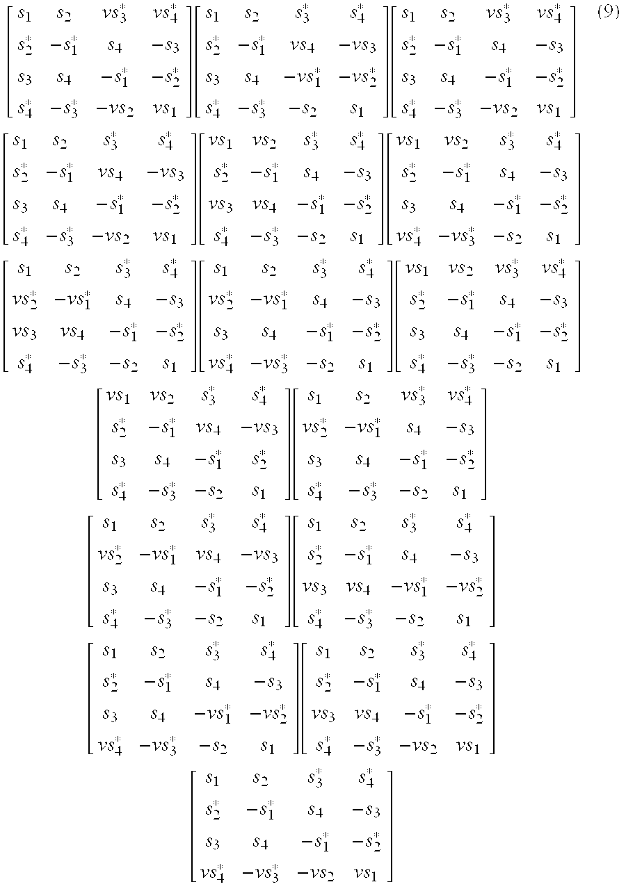
  • As noted from the above matrices, the four input symbols s[0062] 1, s2, s3 and s4 each rotate one time by a predetermined phase value “v”. The phase-rotated matrices are referred to as transmission coding matrices. A total of 384(=24×16)4×4n transmission coding matrices can be produced according to the present invention.
  • FIG. 3 is a block diagram of a transmitter for transmitting one of the transmission coding matrices in the first row of Eq. (9) through four transmit antennas according to an embodiment of the present invention. [0063]
  • Referring to FIG. 3, the transmitter includes an S/[0064] P converter 110, an encoder 120, phase rotators 130 a and 130 b, and four transmit antennas 140 a to 140 d. The S/P converter 110 feeds four input symbols s1, s2, s3 and s4 in one block to the encoder 120. The encoder 120 produces the first matrix of Eq. (8) from the received one-block symbols. Specifically, the encoder 120 generates four combinations each having four symbol elements from the input four symbols and outputs them one by one at four times. The four symbol combinations correspond to the four rows of the matrix and the plurality of symbols are transmitted once through their respective antennas at their respective times.
  • The [0065] phase rotators 130 a and 130 b rotate the phases of two of the four rows received from the encoder 120 by v. When the first transmission coding matrix in Eq. (9) is used, the phase rotators 130 a and 130 b rotate input symbols by v for transmission at first and fourth times, bypassing symbols for transmission at the other times. The resulting symbols are transmitted to a receiver through the transmit antennas 140 a to 140 d.
  • The [0066] encoder 120 and the phase rotators 130 a and 130 b collectively function as a transmission coding matrix generator. While only two rotators 130 a and 130 b are shown, more rotators can be connected between the encoder 120 and corresponding transmit antennas if other transmission coding matrices are adopted.
  • A 4×3 transmission coding matrix for three transmit antennas is generated from a 4×4 transmission coding matrix by selecting two of the four columns of the 4×4 matrix, linearly combining the elements of the selected columns, and replacing the selected columns by a column of the linear elements. Six ways ([0067] 4C2) can be used to select two of the four columns. For example, 4×3 transmission coding matrices derived from the first matrix of Eq. (8) are shown as equation (10): [ ( s 1 + s 2 ) 2 s 3 * s 4 * ( s 2 * - s 1 * ) 2 s 4 - s 3 ( s 3 + s 4 ) 2 - s 1 * - s 2 * ( s 4 * - s 3 * ) 2 - s 2 s 1 ] [ s 1 ( s 2 + s 3 * ) 2 s 4 * s 2 * ( - s 1 * + s 4 ) 2 - s 3 s 3 ( s 4 - s 1 * ) 2 - s 2 * s 4 * ( - s 3 * - s 2 ) 2 s 1 ] [ s 1 s 2 ( s 3 * + s 4 * ) 2 s 2 * - s 1 * ( s 4 - s 3 ) 2 s 3 s 4 ( - s 1 * - s 2 * ) 2 s 4 * - s 3 * ( s 1 - s 2 ) 2 ] [ ( s 1 + s 3 * ) 2 s 2 s 4 * ( s 2 * - s 4 ) 2 - s 1 * - s 3 ( s 3 - s 1 * ) 2 s 4 - s 2 * ( s 4 * - s 2 ) 2 - s 3 * s 1 ] [ s 1 ( s 2 + s 4 * ) 2 s 3 * s 2 * ( - s 1 * - s 3 ) 2 s 4 s 3 ( s 4 - s 2 * ) 2 - s 1 * s 4 * ( - s 3 * + s 1 ) 2 s 2 ] [ s 2 s 3 ( s 1 + s 4 * ) 2 - s 1 * s 4 ( s 2 * - s 3 ) 2 s 4 - s 1 * ( s 3 - s 2 * ) 2 - s 3 * - s 2 ( s 4 * + s 1 ) 2 ] ( 10 )
    Figure US20040072594A1-20040415-M00012
  • Similarly, the above matrices are phase-rotated. Thus, a total of [0068] 1728 4×3 transmission coding matrices are possible.
  • FIG. 4 is a block diagram of a transmitter for transmitting code symbols in a 4×3 transmission coding matrix produced from the first transmission coding matrix of Eq. (9) according to another embodiment of the present invention. [0069]
  • Referring to FIG. 4, the transmitter includes an S/[0070] P converter 210, an encoder 220, rotators 230 a and 230 b, a column generator 240, and three transmit antennas 250 a, 250 b and 250 c. The S/P converter 210 feeds four input symbols s1, s2, s3 and s4 in one block to the encoder 220. The encoder 220 produces the first matrix of Eq. (8) from the received one-block symbols. Specifically, the encoder 220 generates four combinations each having four symbol elements from the input four symbols and outputs them one by one over four time periods. The four symbol combinations correspond to the four rows of the matrix and the plurality of symbols are transmitted once through their respective antennas at their respective time periods.
  • The [0071] phase rotators 230 a and 230 b rotate the phases of two of the four rows received from the encoder 220 by v. When the first transmission coding matrix in Eq. (9) is used, the phase rotators 130 a and 130 b rotate input symbols by v for transmission at first and fourth times, bypassing symbols for transmission at the other times.
  • The [0072] column generator 240 linearly combines the symbol of the second column with the symbol received from the phase rotator 230 a at each transmission time and outputs the combined symbol to the transmit antenna 250 b. The outputs of the encoder 230, the column generator 240, and the phase rotator 230 b are transmitted to the receiver through the transmit antennas 250 a, 250 b and 250 c.
  • The [0073] encoder 220, the phase rotators 230 a and 230 b, and the column generator 240 collectively function as a transmission coding matrix generator. While only two rotators 230 a and 230 b are shown and the column generator 240 combines the symbols of the second and third columns, more rotators can be connected between the encoder 220 and corresponding transmit antennas and the column generator 240 can be disposed at a different corresponding position if other transmission coding matrices are adopted.
  • Examples of desirable transmission coding matrices for three and four transmit antennas are illustrated below. [0074]
  • With respect to a BPSK constellation, the transmission matrix is given in equation (11) by [0075] U 1 = ( s 1 s 2 + j s 3 2 s 4 - s 2 * s 1 * - j s 4 * 2 s 3 * - s 4 * - s 3 * + j s 2 * 2 s 1 * s 3 - s 4 - j s 1 2 s 2 )
    Figure US20040072594A1-20040415-M00013
  • for three transmit antennas. For four transmit antennas, the transmission matrix is [0076] U 2 = ( s 1 s 2 j s 3 s 4 - s 2 * s 1 * - j s 4 * s 3 * - s 4 * - s 3 * j s 2 * s 1 * s 3 - s 4 j s 1 s 2 ) ( 11 )
    Figure US20040072594A1-20040415-M00014
  • With respect to a QPSK constellation, the transmission matrix for three antennas is given in equation (12) by [0077] U 3 = ( s 1 s 2 + s 3 2 s 4 - s 2 * s 1 * - vs 4 * 2 vs 3 * - s 4 * - s 3 * + s 2 * 2 s 1 * s 3 - s 4 - vs 1 2 vs 2 )
    Figure US20040072594A1-20040415-M00015
  • where v=e[0078] −j2π/3 for example. For four transmit antennas, the transmission matrix is U 4 = ( s 1 s 2 s 3 s 4 - s 2 * s 1 * - vs 4 * vs 3 * - s 4 * - s 3 * s 2 * s 1 * s 3 - s 4 - vs 1 vs 2 ) ( 12 )
    Figure US20040072594A1-20040415-M00016
  • where v=e[0079] −j2π/3 for example.
  • With respect to an 8PSK constellation, the transmission matrix for three antennas is given in equation (13) by [0080] U 5 = ( s 1 s 2 + s 3 2 s 4 - s 2 * s 1 * - vs 4 * 2 vs 3 * - s 4 * - s 3 * + s 2 * 2 s 1 * s 3 - s 4 - vs 1 2 vs 2 )
    Figure US20040072594A1-20040415-M00017
  • where v=e[0081] −j5π/6 for example. For four transmit antennas, the transmission matrix is U 6 = ( s 1 s 2 s 3 s 4 - s 2 * s 1 * - vs 4 * vs 3 * - s 4 * - s 3 * s 2 * s 1 * s 3 - s 4 - vs 1 vs 2 ) ( 13 )
    Figure US20040072594A1-20040415-M00018
  • where c=e[0082] −j5π/6 for example,
  • With respect to an 16PSK constellation, the transmission matrix for three antennas is given in equation (14) by [0083] U 7 = ( s 1 s 2 + s 3 2 s 4 - s 2 * s 1 * - vs 4 * 2 vs 3 * - s 4 * - s 3 * + s 2 * 2 s 1 * s 3 - s 4 - vs 1 2 vs 2 )
    Figure US20040072594A1-20040415-M00019
  • where v=e[0084] −j5π/12 for example. For four transmit antennas, the transmission matrix is U 8 = ( s 1 s 2 s 3 s 4 - s 2 * s 1 * - vs 4 * vs 3 * - s 4 * - s 3 * s 2 * s 1 * s 3 - s 4 - vs 1 vs 2 ) ( 14 )
    Figure US20040072594A1-20040415-M00020
  • where v=e[0085] −j5π/12 for example.
  • With respect to an 64QAM constellation, the transmission matrix for three antennas is given in equation (15) by [0086] U 9 = ( s 1 s 2 + s 3 2 s 4 - s 2 * s 1 * - vs 4 * 2 vs 3 * - s 4 * - s 3 * + s 2 * 2 s 1 * s 3 - s 4 - vs 1 2 vs 2 )
    Figure US20040072594A1-20040415-M00021
  • where v=e[0087] −j7π/48 for example. For four transmit antennas, the transmission matrix is U 10 = ( s 1 s 2 s 3 s 4 - s 2 * s 1 * - vs 4 * vs 3 * - s 4 * - s 3 * s 2 * s 1 * s 3 - s 4 - vs 1 vs 2 ) ( 15 )
    Figure US20040072594A1-20040415-M00022
  • where v=e[0088] −j7π/48 for example.
  • Also in accordance with the present invention, described below is a receiver that can decode symbols of the above transmission coding matrices by ML decoding (first embodiment), by super-fast decoding (second embodiment) that renders the ML decoding more efficient, or by sub-optimal decoding (third embodiment). [0089]
  • Decoding According to the First Embodiment [0090]
  • FIG. 5 is a block diagram of a receiver that decodes according to an embodiment of the present invention. The receiver is comprised of two [0091] independent decoders 340 and 345.
  • Referring to FIG. 5, a [0092] channel estimator 320 estimates channel coefficients representing channel gains from a plurality of transmit antennas to a plurality of receive antennas 310. A symbol arranger 330 collects symbols received from the receive antennas 310 for the four time periods corresponding to transmission by the transmitter illustrated in FIG. 3 or FIG. 4 of one block of symbols at four times.
  • The [0093] symbol arranger 330 forms a matrix out of the collected symbols. In the matrix, symbols received from the same receive antenna are arranged in the same row and symbols received at the same time are arranged in the same column. Although the plurality of receive antennas 310 are illustrated, decoding for the case of one antenna will be described below, for notational simplicity.
  • If four symbols to be detected are x[0094] 1, x2, x3 and x4, the first decoder 340 detects x1 and x3 and the second decoder 345 detects x2 and x4, based on the channel gains and the received symbols. Thus, the decoders 340 and 345 detect the four symbols x1, x2, x3 and x4 simultaneously.
  • In the [0095] first decoder 340, a symbol generator 350 generates all possible symbol pairs and phase rotators 360 and 362 rotate at least one symbol of each symbol pair by the phase value v used in the transmitter or by 1.
  • A [0096] metric calculator 370 calculates the metric values of the resulting phase-rotated symbol pairs. The number of all possible symbol pairs is 2×2 for BPSK, 4×4 for QPSK, 8×8 for 8PSK, 16×16 for 16QAM, and 64×64 for 64QAM. A minimum metric detector 380 detects symbols x1 and x3 that have a minimum metric.
  • The [0097] second decoder 345 operates in the same manner. After the first and second decoders 340 and 345 detect x1 & x3 and x2 & x4, respectively, a parallel-to-serial (P/S) converter 390 arranges the detected symbols in the right order and outputs the recovered symbol combination of x1, x2, x3, and x4.
  • For notational simplicity, a description will be made below of decoding for BPSK symbols, U[0098] 1 illustrated in matrix (11) transmitted from three transmit antennas for the case of one receive antenna, with channel gains from the first, second and third transmit antennas to the receiver of α, β and γ, respectively. The signal r, received at the receive antenna at time t is given by equation (16): r 1 = α s 1 + β s 2 + s 3 2 + γ s 4 + n 1 , r 2 = - α s 2 * + β s 1 * - j s 4 * 2 + γ s 3 * + n 2 , r 3 = - α s 4 * + β - s 3 * + j s 2 * 2 + γ s 1 * + n 3 , r 4 = α s 3 + β - s 4 - j s 1 2 + γ s 2 + n 4 , ( 16 )
    Figure US20040072594A1-20040415-M00023
  • where s[0099] 1, s2, s3 and s4 are symbols transmitted from the transmitter and n1, n2, n3 and n4 are noise involved with the transmission at the four times. For U1, the receiver computes symbols x1, x2, x3, and x4 that minimize the sum as shown in equation (17): r 1 - ( α x 1 + β x 2 + x 3 2 + γ x 4 ) 2 + r 2 - ( - α x 2 * + β x 1 * - j x 4 * 2 + γ x 3 * ) 2 + r 3 - ( - α x 4 * + β - x 3 * + j x 2 * 2 + γ x 1 * ) 2 + r 4 - ( α x 3 + β - x 4 - j x 1 2 + γ x 2 ) 2 ( 17 )
    Figure US20040072594A1-20040415-M00024
  • The sum decomposes into two parts. The first part contains only x[0100] 1 and x3 and the second part contains only x2 and x4. Thus, the receiver illustrated in FIG. 5 is constituted by decoupling the first decoder 340 for decoding the pair of x1 and x3 from the second decoder 345 for decoding the pair of x2 and x4.
  • The above operation for the transmission coding matrices U[0101] 1, U3, U5, U7 and U9 transmitted from three transmit antennas will be described in more detail.
  • For ML decoding for U[0102] 1, as shown in equation (18), letting R 1 = α * r 1 + β 1 2 r 2 * + γ r 3 * + j β * 1 2 r 4 R 3 = γ r 2 * - j β * 1 2 r 1 + α * r 4 - β * 1 2 r 3 * R 13 = j ( C 1 + C 3 ) 2 C 1 = - α * β 2 - α β * 2 C 3 = j γ * β 2 - j γ β * 2 ( 18 )
    Figure US20040072594A1-20040415-M00025
  • the [0103] first decoder 340 minimizes the sum as shown in equation (19):
  • |R1−x1|2+|R3−x3|2+|R13−x1*x3|2  (19)
  • over all possible symbol pairs and detects the minimizing symbol pair x[0104] 1 and x3.
  • Similarly, as shown in equation (20), letting [0105] R 2 = β * 1 2 r 1 - α r 2 * + j β 1 2 r 3 * + γ * r 4 R 4 = γ * r 1 - j β 1 2 r 2 * - α r 3 * - β * 1 2 r 4 R 24 = j ( C 2 + C 4 ) 2 C 2 = α β * 2 + α * β 2 C 4 = j γ β * 2 - j γ * β 2 ( 20 )
    Figure US20040072594A1-20040415-M00026
  • the [0106] second decoder 345 minimizes the sum as shown in equation (21):
  • |R2−x2|2+|R4−x4|2+|R24−x2*x4|2  (21)
  • over all the possible symbol pairs and detects the minimizing symbol pair x[0107] 2 and x4.
  • For ML decoding for U[0108] 3 or U5, as shown in equation (22), letting R 1 = α * r 1 + β 1 2 r 2 * + γ r 3 * - ν * β * 1 2 r 4 R 3 = ν γ r 2 * - β * 1 2 r 1 + α * r 4 - β 1 2 r 3 * R 13 = - ( C 1 + C 3 ) 2 C 1 = - α * β ν 2 - α β * 2 C 3 = γ β * ν 2 - γ * β 2 ( 22 )
    Figure US20040072594A1-20040415-M00027
  • where v is the phase value by which the phase of a symbol is rotated, e[0109] −j2π/3 for U3 and e−j5π/6 for U5, for example, the first decoder 340 minimizes the sum as shown in equation (23):
  • |R1−x1|2+|R3−x3|2+|R13−x1*x3|2  (23)
  • over all possible symbol pairs and detects the minimizing symbol pair x[0110] 1 and x3.
  • Similarly, as shown in equation (24), letting [0111] R 2 = β * 1 2 r 1 - α r 2 * + β 1 2 r 3 * + ν * γ * r 4 R 4 = γ * r 1 - ν β 1 2 r 2 * - α r 3 * - β * 1 2 r 4 R 24 = - ( C 2 + C 4 ) 2 C 2 = - α β * 2 + ν α * β 2 C 4 = - ν γ β * 2 + γ * β 2 ( 24 )
    Figure US20040072594A1-20040415-M00028
  • the [0112] second decoder 345 minimizes the sum as shown in equation (25):
  • |R2−x2|2+|R4−x4|2+|R24−x2*x4|2  (25)
  • over all the possible symbol pairs and detects the minimizing symbol pair x[0113] 2 and x4.
  • For ML decoding for U[0114] 7 or U9, as shown in equation (26), letting R 1 = ( α * r 1 + β 1 2 r 2 * + γ r 3 * - ν * β * 1 2 r 4 ) K 3 R 3 = ( ν γ r 2 * + β * 1 2 r 1 + α * r 4 - β 1 2 r 3 * ) K 3 R 13 = - ( C 1 + C 3 ) 2 K 3 K 3 = α 2 + β 2 + γ 2 C 1 = - α * β ν 2 + α β * 2 C 3 = γ β * ν 2 - γ * β 2 ( 26 )
    Figure US20040072594A1-20040415-M00029
  • where v=e[0115] −j5π/12 for U7 and v=e−j7π/48 for U9, for example, the first decoder 340 minimizes the sum as shown in equation (27):
  • |R1−x1|2+|R3−x3|2+|R13−x1*x3|2−|x1|2|x3|2  (27)
  • over all possible symbol pairs and detects the minimizing symbol pair x[0116] 1 and x3.
  • Similarly, as shown in equation (28), letting [0117] R 2 = ( β * 1 2 r 1 - α r 2 * + β 1 2 r 3 * + ν * γ * r 4 ) K 3 R 4 = ( γ * r 1 - ν β 1 2 r 2 * - α r 3 * - β * 1 2 r 4 ) K 3 R 24 = - ( C 2 + C 4 ) 2 K 3 C 2 = - α β * 2 + ν α * β 2 C 4 = - ν γ β * 2 + γ * β 2 ( 28 )
    Figure US20040072594A1-20040415-M00030
  • the [0118] second decoder 345 minimizes the sum as shown in equation (29):
  • |R2−x2|2+|R4−x4|2+|R24−x2*x4|2−|x2|2|x4|2  (29)
  • over all the possible symbol pairs and detects the minimizing symbol pair x[0119] 2 and x4.
  • Now, ML decoding for modulation symbols transmitted from four transmit antennas will be described with reference to one receive antenna, with channel gains from the first to fourth transmit antennas to the receiver of α, β, γ, and ξ, respectively. [0120]
  • For ML decoding for U[0121] 2, as shown in equation (30), letting
  • R 1 =α*r 1 +βr 2 *+ζr 3 *+jγ*r 4
  • R 3 =ζr 2 *−jγ*r 1 +α*r 4 −βr 3*
  • R 13=−(C 1 +C 3)
  • C1 =jα*γ+jαγ*
  • C 3=ζ*β−ζβ*  (30)
  • the [0122] first decoder 340 minimizes the sum as shown in equation (31):
  • |R1−x1|2+|R3−x3|2+|R13−x1x3*|2  (31)
  • over all possible symbol pairs and detects the minimizing symbol pair x[0123] 1 and x3.
  • Similarly, as shown in equation (32), letting [0124]
  • R 2 =β*r 1 −αr 2 *+jγr 3 *+ζ*r 4
  • R 4 =ζ*r 1 −jγr 2 *−αr 3 *−β*r 4
  • R 24=−(C 2 +C 4)
  • C 2=ζβ*−ζ*β
  • C 4 =−jαγ*−jγα*  (32)
  • the [0125] second decoder 345 minimizes the sum as shown in equation (33):
  • |R2−x2|2+|R4−x4|2+|R24−x2x4*|2  (33)
  • over all the possible symbol pairs and detects the minimizing symbol pair x[0126] 2 and x4.
  • For ML decoding for U[0127] 4 or U6, as shown in equation (34), letting
  • R 1 =α*r 1 +βr 2*+ζr3 *−ν*γ*r 4
  • R 3 =νζr 2*+γ*r1 +α*r 4 −βr 3*
  • R 13=−(C 1 +C 3)
  • C 1=−α*γν+αγ*
  • C 3=ζβ*ν−ζ*β  (34)
  • where v=e[0128] −j2π/3 for U4 and v=e−j5π/6 for U6, for example, the first decoder 340 minimizes the sum as shown in equation (35):
  • |R1−x1|2+|R3−x3|2+|R13−x1*x3|2  (35)
  • over all possible symbol pairs and detects the minimizing symbol pair x[0129] 1 and x3.
  • Similarly, as shown in equation (36), letting [0130]
  • R 2 =β*r 1 −αr 2 *+γr 3 +ν*ζ*r 4
  • R 4 =ζ*r 1 −νγr 2 *−αr 3 *−β*r 4
  • R 24=−(C 2 +C 4)
  • C 2=−αγ*+να*γ
  • C 4=−νζβ*+ζ*β  (36)
  • the [0131] second decoder 345 minimizes the sum as shown in equation (37):
  • |R2−x2|2+|R4−x4|2+|R24−x2*x4|2  (37)
  • over all the possible symbol pairs and detects the minimizing symbol pair x[0132] 2 and x4.
  • For ML decoding for U[0133] 8 or U10, as shown in equation (38), letting R 1 = ( α * r 1 + β r 2 * + ζ r 3 * - v * γ * r 4 ) K 4 R 3 = ( v ζ r 2 * + γ * r 1 + α * r 4 - β r 3 * ) K 4 R 13 = - ( C 1 + C 3 ) K 4 K 4 = α 2 + β 2 + γ 2 C 1 = - α * γ v + α γ * C 3 = ζ β * v - ζ * β ( 38 )
    Figure US20040072594A1-20040415-M00031
  • where v=e[0134] −j5π/12 for U8 and v−e−j7π/48 for U10, for example, the first decoder 340 minimizes the sum as shown in equation (39):
  • |R1−x1|2+|R3−x3|2+|R13−x1*x3|2−|x1|2|x3|2  (39)
  • over all possible symbol pairs and detects the minimizing symbol pair x[0135] 1 and x3.
  • Similarly, as shown in equation (40), letting [0136] R 2 = ( β * r 1 - α r 2 * + γ r 3 * + v * ζ * r 4 ) K 4 R 4 = ( ζ * r 1 - v γ r 2 * - α r 3 * - β * r 4 ) K 4 R 24 = - ( C 2 + C 4 ) K 4 C 2 = - α γ * + v α * γ C 4 = - v ζ β * + ζ * β ( 40 )
    Figure US20040072594A1-20040415-M00032
  • the [0137] second decoder 345 minimizes the sum as shown in equation (41):
  • |R2−x2|2+|R4−x4|2+|R24−x2*x4|2−|x2|2|x4|2  (41)
  • over all the possible symbol pairs and detects the minimizing symbol pair x[0138] 2 and x4.
  • Decoding According to the Second Embodiment [0139]
  • For ML decoding according to the first embodiment, the metric values of all possible symbol pairs must be computed to detect desired symbols. Thus, 8×8 metric calculations are required for 8PSK, and 16×16 metric calculations for 16QAM. These codes can be decoded very quickly by reducing the number of required computations utilizing the characteristics of PSK and QAM. [0140]
  • FIGS. 6A, 6B and [0141] 6C illustrate BPSK, QPSK, and 8PSK signal constellations, respectively. As shown, all PSK modulation symbols lie on a unit circle, which implies that their length is always 1.
  • For U[0142] 6, since x1 and x3 both have length l, as shown in equation (42), minimizing the metric (35) is equivalent to minimizing
  • |R1−x1|2+|R3−x3|2+|x1R13−x3|2  (42)
  • For each fixed x[0143] 1, as shown in equation (43), minimizing the sum of equation (42) is equivalent to minimizing
  • |(R3+x1R13)−x3|2  (43)
  • Since x[0144] 1 is fixed, minimizing the metric of equation (43) is equivalent to finding the closest constellation point x3 to R3+x1R13. It is possible to have one x3 for each x1. Thus, the receiver detects a symbol pair (x1, x3) that minimizes the ML decoding metric of the first embodiment as desired reception symbols. For x2 and x4, the receiver similarly finds the closest constellation point x4 to R4+x2R24 and detects a symbol pair (x2, x4) that minimizes the ML decoding metric as desired x2 and x4. The same procedure is applied to other PSK transmission coding matrices.
  • With regard to QAM decoding, all 16QAM or 64QAM symbols have different lengths, as illustrated in FIGS. 7[0145] a and 7B, and the metric (39) is used for QAM codes. When x1 is fixed, as shown in equation (44), minimizing the metric (39) over all possible values for x3 is equivalent to minimizing
  • |(R3+x1R13)−x3|2+|R1−x1|2  (44)
  • For each fixed x[0146] 1, minimizing the metric of equation (44) is equivalent to finding the closest constellation point x3 to R3+x1R13. Thus, the receiver detects all symbol pairs (x1, x3) and detects the minimizing symbol pair (x1, x3). For x2 and x4, the receiver similarly finds the closest constellation point x4 to R4+x2R24 and detects the minimizing symbol pair (x2, x4). The same procedure is applied to other QAM transmission coding matrices.
  • FIG. 8 is a flowchart illustrating the second embodiment of decoding according to the present invention. While the procedure is described as being performed for detection of only one symbol pair, it is to be noted that the other symbol pairs are detected in the same manner. [0147]
  • Referring to FIG. 8, thresholds m[0148] 1 and m2 are set to a very small number, for example, 10−10 and symbol index i is set to 0 in step 402. The receiver computes parameters R1, R2, and R13 using signals received for a plurality of time periods and estimated channel gains in step 404. In step 406, a first symbol x1 is set to si. The receiver computes g(x1)=R3+x1R13 in step 408. The receiver sets variable j to an initial value 0 in step 410, sets a second symbol x3 to sj in step 412, and computes A(x3)=|g(x1)−x3|2 in step 414.
  • In [0149] step 416, A(x3) is compared with threshold m1. If A(x3) is equal to or greater than threshold m1, the receiver proceeds to step 420. On the contrary, if A(x3) is less than m1, m1 is updated to A(x3) and y(x3) is set as x3 in step 418. In step 420, it is determined whether x3 is the last symbol, for example, if i=16 for 16QAM. If it is, it is determined that the second symbol sj matching the first symbol s1 has been detected and the receiver proceeds to step 424. Otherwise, the receiver increases variable j by 1 in step 422 and returns to step 412.
  • In [0150] step 424, the receiver computes B(x3)=|R1−x1|2+|R3−y(x3)|2+|R13−x1*y(x3)|2. If B(x3) is equal to or greater than threshold m2, the receiver proceeds to step 430. Otherwise, it proceeds to step 428. The receiver updates m2 to B(x3) and sets y(x1) as x1 in step 428. In step 430, it is determined whether x1 is the last symbol, for example, if i=16 for 16QAM. If it is, it is determined that the second symbols sj matching all first symbols s1 have been detected and the receiver proceeds to step 434. Otherwise, the receiver increases variable i by 1 in step 432 and returns to step 406. In step 434, the receiver finally detects y(x1) and y(x3).
  • FIG. 9 is a block diagram of a receiver that decodes according to the second embodiment of the present invention. The receiver is comprised of two [0151] independent decoders 540 and 545.
  • Referring to FIG. 9, a [0152] channel estimator 520 estimates channel coefficients representing channel gains from a plurality of transmit antennas to a plurality of receive antennas 510. A symbol arranger 530 collects symbols received from the receive antennas 510 for the four time periods corresponding to transmission by the transmitter illustrated in FIG. 3 or FIG. 4 of one block of symbols at four times.
  • The [0153] symbol arranger 530 forms a matrix out of the collected symbols. In the matrix, symbols received from the same receive antenna are arranged in the same row and symbols received at the same time are arranged in the same column. Although the plurality of receive antennas 510 are illustrated, decoding for the case of one antenna will be described below, for notational simplicity.
  • If four symbols to be detected are x[0154] 1, x2, x3 and x4, the first decoder 540 detects x1 and x3 and the second decoder 545 detects x2 and x4, based on the channel gains and the received symbols. Thus, the decoders 540 and 545 detect the four symbols x1, x2, x3 and x4 simultaneously.
  • In the [0155] first decoder 540, a symbol generator 550 generates all possible symbol pairs and phase rotators 552 and 554 rotate at least one symbol of each symbol pair by the phase value v used in the transmitter or by 1. The number of all possible symbol pairs is the square of a modulation order used, for example, 162 for 16QAM.
  • A [0156] symbol selector 560 computes the parameters R1, R3, and R13 and selects symbol pairs that minimize the metric (43) or (44) according to the parameters. The number of the selected symbol pairs is equal to the modulation order. For example, 16 symbol pairs are selected according to the metric (44), for 16QAM.
  • A [0157] metric calculator 570 calculates the metric values of the selected symbol pairs using the parameters according to a modulation scheme and the number of the transmit antennas. A minimum metric detector 580 detects one symbol pair having a minimum metric value using the computed metric values. The metric computation is performed by Eq. (19), (23), (27), (31), (35) or (39) shown above.
  • The [0158] second decoder 545 operates in the same manner. After the first and second decoders 540 and 545 detect x1 & x3 and x2 & x4, respectively, a P/S converter 590 arranges the detected symbols in the right order and outputs the recovered symbol combination of x1, x2, x3, and x4.
  • Assuming a 2[0159] b PSK signal constellation, once R1, R3 and R13 are computed, b summations and 2b multiplications are required for computation of g(x1), 2b comparisons, one for each g(x1), are required for computing y(x3), and finally 3×2b multiplications and additions are performed for computing B(x3). Therefore, the same symbol detection performance as that of the ML decoding according to the first embodiment can be achieved with a total of 4×2b additions and multiplications and 2b comparisons according to the second embodiment of the present invention.
  • Decoding According to the Third Embodiment [0160]
  • QPSK or 8PSK symbols can be decoded with a reduced volume of computations despite a lower symbol detection performance, as compared to decoding methods according to the first and second embodiments. [0161]
  • For 8PSK symbols, the receiver computes the parameters R[0162] 1, R3 and R13 and finds the closest constellation points q1 to R1, q3 to R3, and q13 to R13. If q13=q1*q3, the receiver outputs q1 and q3.
  • If not, the receiver computes an angle Φ[0163] d by dividing the angle between ql3 and q1*q3 by 2. Then the receiver searches for desired first and second symbols by calculating the ML decoding metric values of first symbol and second symbol candidates whose angles are respectively within the angular distance Φd from q1 and q3.
  • Similarly, the receiver computes the parameters R[0164] 2, R4 and R24 and finds the closest constellation points q2 to R2, q4 to R4, and q24 to R24. If q24=q2*q4, the receiver outputs q2 and q4.
  • If not, the receiver computes an angle Φ[0165] d′ by dividing the angle between q24 and q2*q4 by 2. Then the receiver searches for desired first and second symbols by calculating the ML decoding metric values of first symbol and second symbol candidates whose angles are respectively within the angular distance Φd′ from q2 and q4.
  • FIGS. 10A and 10B illustrate 8PSK signal constellations to depict sub-optimal decoding according to the present invention. Referring to FIG. 10A, the closest constellation point q[0166] 1 to R1 is ej(3π/4), the closest constellation point q3 to R3 is ej(−π/4), and the closest constellation point q13 to R13 is ej(π/4). q1*q3 is ej(π) and Φd′=3π/8.
  • Referring to FIG. 10B, the receiver searches for a symbol pair that minimizes the ML decoding metric over all possible symbol pairs made out of first symbol candidates s[0167] 2, s3 and s4 which are within 3π/8 from q1 and second symbol candidates s0, s6 and s7 which are within 3π/8 from q3. The same process is applied to other PSK transmission coding matrices.
  • FIG. 11 is a flowchart illustrating decoding according to the third embodiment of the present invention. For notational simplicity, the decoding is carried out for only one symbol pair. [0168]
  • Referring to FIG. 11, the receiver computes the parameters R[0169] 1, R3 and R13 in step 602 and finds the closest constellation points x1 to R1, x3 to R3, and x13 to R13 in step 604. If x13=x1*x3 in step 606, the receiver outputs x1 and x3.
  • If not, the receiver computes [0170] Φ d = 1 2 ( x 13 x 1 * x 3 )
    Figure US20040072594A1-20040415-M00033
  • in [0171] step 608 and selects first symbol and second symbol candidates whose angles are respectively within the angular distance Φd from x1 and x3 in step 610. In step 612, the receiver detects a symbol pair that minimizes the ML decoding metric of the first embodiment by calculating the ML decoding metric values of all possible symbol pairs made out of the first and second symbol candidates.
  • For the sub-optimal decoding, the receiver is configured in hardware as illustrated in FIG. 9. The [0172] symbol selector 560 computes the parameters R1, R3 and R13, finds the closest constellation points to R1, R3, and to R13, computes the angle Φd, and selects candidate symbols within Φd from the constellation points. For QPSK, up to 3×3 candidate symbol pairs are produced from the candidate symbols and for 8PSK, the number of the candidate symbol pairs is up to 5×5.
  • The [0173] metric calculator 570 calculates the metric values of the symbol pairs using Eq. (19), (23), (27), (31), (35), or (39) and the minimum metric detector 580 detects one symbol pair having a minimum metric value.
  • The [0174] second decoder 545 operates in the same manner. Thus, the first decoder 540 detects x1 and x3 and the second decoder 545 detects x2 and x4. The P/S converter 590 arranges the detected symbols in the right order and outputs the recovered symbol combination of x1, x2, x3 and x4.
  • FIGS. 12, 13 and [0175] 14 are graphs illustrating SER versus SNR from ML decoding for BPSK, QPSK, and 8PSK, respectively, assuming 2, 3 and 4 transmit antennas and, for example, one receive antenna in the first embodiment of the present invention.
  • In FIG. 12, [0176] reference numerals 700, 702 and 704 denote SERs for 2, 3, and 4 transmit antennas, respectively. In FIG. 13, reference numerals 710, 712 and 714 denote SERs for 2, 3, and 4 transmit antennas, respectively. In FIG. 14, reference numerals 720, 722 and 724 denote SERs for 2, 3, and 4 transmit antennas, respectively.
  • The relation between SER and SNR is given by equation (45): [0177]
  • SER=C·SNR −d  (45)
  • where C is a constant and d is a diversity gain. Therefore, log(SER)=−d·log(C·SNR) in FIGS. 12, 13 and [0178] 14. With log(SNR) on an X axis, y=−dx. Thus, d is the inclination. In other words, the inclination of the SER-SNR graph on a log scale is the diversity gain. As noted from FIGS. 12, 13 and 14, the transmit diversity of the present invention offers a diversity order equal to the number of transmit antennas, that is, a maximum diversity order.
  • FIG. 15 is a graph comparing SERs between the decoding schemes of the first and third embodiments for four transmit antennas transmitting 8PSK symbols according to the present invention. [0179] Reference numeral 732 denotes the sub-optimal decoding according to the third embodiment and reference numeral 730 denotes the ML decoding according to the first embodiment. The sub-optimal decoding still provides a maximum diversity gain despite a slightly degraded performance as compared to the ML decoding.
  • As described above, the present invention advantageously provides a maximum diversity gain for space-time block codes with three or more transmit antennas and simplifies the structure of a decoder for detecting transmission symbols in a receiver. Therefore, a data processing rate is increased and system development cost is saved. [0180]
  • While the invention has been shown and described with reference to certain preferred embodiments thereof, it will be understood by those skilled in the art that various changes in form and details may be made therein without departing from the spirit and scope of the invention as defined by the appended claims. [0181]

Claims (35)

What is claimed is:
1. A transmitter for transmitting modulation symbols in a wireless communication system, comprising:
a plurality of transmit antennas for achieving transmit diversity; and
a transmission coding matrix generator for producing a plurality of symbol combinations with a plurality of input symbols to transmit the input symbols once from each transmit antenna at each time period, forming a transmission coding matrix with rows corresponding to transmission time periods and columns corresponding to transmit antennas from the symbol combinations, and outputting the symbol combinations to the transmit antennas at a plurality of times, the transmission coding matrix having at least two columns orthogonal to each other and the symbol combinations having as elements the input symbols, the inversions and conjugates of the symbols, and symbols obtained by rotating the phases of some of the symbols once by a predetermined phase value to maximize a diversity gain.
2. The transmitter of claim 1, wherein if the number of the transmit antennas is 4, the transmission coding matrix generator comprises:
an encoder for generating a transmission coding matrix with four rows and four columns from four input symbols, and the inversions and the conjugates of the four symbols; and
at least two phase rotators for selectively rotating the phases of symbols in at least two of the columns of the transmission coding matrix by the predetermined phase value.
3. The transmitter of claim 2, wherein the transmission coding matrix is one of
[ s 1 s 2 s 3 * s 4 * s 2 * - s 1 * s 4 - s 3 s 3 s 4 - s 1 * - s 2 * s 4 * - s 3 * - s 2 s 1 ] [ s 1 s 2 s 3 * - s 4 * s 2 * - s 1 * s 4 s 3 s 3 s 4 - s 1 * s 2 * s 4 * - s 3 * - s 2 - s 1 ] [ s 1 s 2 s 3 * - s 4 * s 2 * - s 1 * - s 4 - s 3 s 3 s 4 - s 1 * s 2 * s 4 * - s 3 * s 2 s 1 ] [ s 1 s 2 s 3 * s 4 * s 2 * - s 1 * - s 4 s 3 s 3 s 4 - s 1 * - s 2 * s 4 * - s 3 * s 2 - s 1 ] [ s 1 s 2 - s 3 * - s 4 * s 2 * - s 1 * s 4 - s 3 s 3 s 4 s 1 * s 2 * s 4 * - s 3 * - s 2 s 1 ] [ s 1 s 2 - s 3 * s 4 * s 2 * - s 1 * s 4 s 3 s 3 s 4 s 1 * - s 2 * s 4 * - s 3 * - s 2 - s 1 ] [ s 1 s 2 - s 3 * - s 4 * s 2 * - s 1 * - s 4 s 3 s 3 s 4 s 1 * s 2 * s 4 * - s 3 * s 2 - s 1 ] [ s 1 s 2 - s 3 * s 4 * s 2 * - s 1 * - s 4 - s 3 s 3 s 4 s 1 * - s 2 * s 4 * - s 3 * s 2 s 1 ]
Figure US20040072594A1-20040415-M00034
where s1, s2, s3 and s4 are the four input symbols.
4. The transmitter of claim 2, wherein if the input symbols are BPSK (Binary Phase Shift Keying) symbols, the transmission coding matrix is
U 2 = ( s 1 s 2 j s 3 s 4 - s 2 * s 1 * - j s 4 * s 3 * - s 4 * - s 3 * j s 2 * s 1 * s 3 - s 4 - j s 1 s 2 )
Figure US20040072594A1-20040415-M00035
where s1, s2, s3 and s4 are the four input symbols.
5. The transmitter of claim 2, wherein if the input symbols are QPSK (Quadrature Phase Shift Keying) symbols, the transmission coding matrix is
U 4 = ( s 1 s 2 s 3 s 4 - s 2 * s 1 * - v s 4 * v s 3 * - s 4 * - s 3 * s 2 * s 1 * s 3 - s 4 - v s 1 v s 2 )
Figure US20040072594A1-20040415-M00036
where s1, s2, s3 and s4 are the four input symbols and v is the predetermined phase value.
6. The transmitter of claim 5, wherein v is e−j2π/3.
7. The transmitter of claim 2, wherein if the input symbols are 8PSK (8-ary Phase Shift Keying) symbols, the transmission coding matrix is
U 6 = ( s 1 s 2 s 3 s 4 - s 2 * s 1 * - v s 4 * v s 3 * - s 4 * - s 3 * s 2 * s 1 * s 3 - s 4 - v s 1 v s 2 )
Figure US20040072594A1-20040415-M00037
where s1, s2, s3 and s4 are the four input symbols and v is the predetermined phase value.
8. The transmitter of claim 7, wherein v is e−j5π/6.
9. The transmitter of claim 2, wherein if the input symbols are 16QAM (16-ary Quadrature Amplitude Modulation) symbols, the transmission coding matrix is
U 8 = ( s 1 s 2 s 3 s 4 - s 2 * s 1 * - v s 4 * v s 3 * - s 4 * - s 3 * s 2 * s 1 * s 3 - s 4 - v s 1 v s 2 )
Figure US20040072594A1-20040415-M00038
where s1, s2, s3 and s4 are the four input symbols and v is the predetermined phase value.
10. The transmitter of claim 9, wherein v is e−j5π/12.
11. The transmitter of claim 2, wherein if the input symbols are 64QAM (64-ary Quadrature Amplitude Modulation) symbols, the transmission coding matrix is
U 10 = ( s 1 s 2 s 3 s 4 - s 2 * s 1 * - v s 4 * v s 3 * - s 4 * - s 3 * s 2 * s 1 * s 3 - s 4 - v s 1 v s 2 )
Figure US20040072594A1-20040415-M00039
where s1, s2, s3 and s4 are the four input symbols and v is the predetermined phase value.
12. The transmitter of claim 11, wherein v is e−j7π/48.
13. The transmitter of claim 1, wherein if the number of the transmit antennas is 3, the transmission coding matrix generator comprises:
an encoder for generating a transmission coding matrix with four rows and four columns from four input symbols, and the inversions and the conjugates of the four symbols;
at least two phase rotators for selectively rotating the phases of symbols in at least two of the columns of the transmission coding matrix by the predetermined phase value; and
a column generator for generating a new column by summing the symbols of the selected two columns containing phase-rotated symbols and replacing the selected two columns with the new column, thereby generating a transmission coding matrix with four rows and three columns.
14. The transmitter of claim 13, wherein the transmission coding matrix generated from the encoder is one of
[ s 1 s 2 s 3 * s 4 * s 2 * - s 1 * s 4 - s 3 s 3 s 4 - s 1 * - s 2 * s 4 * - s 3 * - s 2 s 1 ] [ s 1 s 2 s 3 * - s 4 * s 2 * - s 1 * s 4 s 3 s 3 s 4 - s 1 * s 2 * s 4 * - s 3 * - s 2 - s 1 ] [ s 1 s 2 s 3 * - s 4 * s 2 * - s 1 * - s 4 - s 3 s 3 s 4 - s 1 * s 2 * s 4 * - s 3 * s 2 s 1 ] [ s 1 s 2 s 3 * s 4 * s 2 * - s 1 * - s 4 s 3 s 3 s 4 - s 1 * - s 2 * s 4 * - s 3 * s 2 - s 1 ] [ s 1 s 2 - s 3 * - s 4 * s 2 * - s 1 * s 4 - s 3 s 3 s 4 s 1 * s 2 * s 4 * - s 3 * - s 2 s 1 ] [ s 1 s 2 - s 3 * s 4 * s 2 * - s 1 * s 4 s 3 s 3 s 4 s 1 * - s 2 * s 4 * - s 3 * - s 2 - s 1 ] [ s 1 s 2 - s 3 * - s 4 * s 2 * - s 1 * - s 4 s 3 s 3 s 4 s 1 * s 2 * s 4 * - s 3 * s 2 - s 1 ] [ s 1 s 2 - s 3 * s 4 * s 2 * - s 1 * - s 4 - s 3 s 3 s 4 s 1 * - s 2 * s 4 * - s 3 * s 2 s 1 ]
Figure US20040072594A1-20040415-M00040
where s1, s2, s3 and s4 are the four input symbols.
15. The transmitter of claim 13, wherein if the input symbols are BPSK symbols, the transmission coding matrix is
U 1 = ( s 1 s 2 + j s 3 2 s 4 - s 2 * s 1 * - j s 4 * 2 s 3 * - s 4 * - s 3 * + j s 2 * 2 s 1 * s 3 - s 4 - j s 1 2 s 2 )
Figure US20040072594A1-20040415-M00041
where s1, s2, s3 and s4 are the four input symbols.
16. The transmitter of claim 13, wherein if the input symbols are QPSK symbols, the transmission coding matrix is
U 3 = ( s 1 s 2 + s 3 2 s 4 - s 2 * s 1 * - v s 4 * 2 v s 3 * - s 4 * - s 3 * + s 2 * 2 s 1 * s 3 - s 4 - v s 1 2 v s 2 )
Figure US20040072594A1-20040415-M00042
where s1, s2, s3 and s4 are the four input symbols and v is the predetermined phase value.
17. The transmitter of claim 16, wherein v is e−j2π/3.
18. The transmitter of claim 13, wherein if the input symbols are 8PSK symbols, the transmission coding matrix is
U 5 = ( s 1 s 2 + s 3 2 s 4 - s 2 * s 1 * - v s 4 * 2 v s 3 * - s 4 * - s 3 * + s 2 * 2 s 1 * s 3 - s 4 - v s 1 2 v s 2 )
Figure US20040072594A1-20040415-M00043
where s1, s2, s3 and s4 are the four input symbols and v is the predetermined phase value.
19. The transmitter of claim 18, wherein v is e−j5π/6.
20. The transmitter of claim 13, wherein if the input symbols are 16QAM symbols, the transmission coding matrix is
U 7 = ( s 1 s 2 + s 3 2 s 4 - s 2 * s 1 * - v s 4 * 2 v s 3 * - s 4 * - s 3 * + s 2 * 2 s 1 * s 3 - s 4 - v s 1 2 v s 2 )
Figure US20040072594A1-20040415-M00044
where s1, s2, s3 and s4 are the four input symbols and v is the predetermined phase value.
21. The transmitter of claim 20, wherein v is e−j5π/12.
22. The transmitter of claim 13, wherein if the input symbols are 64QAM symbols, the transmission coding matrix is
U 9 = ( s 1 s 2 + s 3 2 s 4 - s 2 * s 1 * - v s 4 * 2 v s 3 * - s 4 * - s 3 * + s 2 * 2 s 1 * s 3 - s 4 - v s 1 2 v s 2 )
Figure US20040072594A1-20040415-M00045
where s1, s2, s3 and s4 are the four input symbols and v is the predetermined phase value.
23. The transmitter of claim 22, wherein v is e−j7π/48.
24. A receiver for receiving modulation symbols whose phases are rotated once from a transmitter in a wireless communication system, comprising:
first and second decoders for detecting symbol pairs that minimize maximum likelihood (ML) decoding metrics over all possible symbol pairs using signals received by a receive antenna from three transmit antennas for four time periods and channel gains from the transmit antennas to the receive antenna,
wherein if the modulation symbols are BPSK (Binary Phase Shift Keying) symbols, the first and second decoders compute parameters
R 1 = α * r 1 + β 1 2 r 2 * + γ r 3 * + j β * 1 2 r 4 R 3 = γ r 2 * - j β * 1 2 r 1 + α * r 4 - β * 1 2 r 3 * R 13 = j ( C 1 + C 3 ) 2 C 1 = - α * β 2 - α β * 2 C 3 = j γ * β 2 - j γ β * 2 R 2 = β * 1 2 r 1 - α r 2 * + j β 1 2 r 3 * + γ * r 4 R 4 = γ * r 1 - j β 1 2 r 2 * - α r 3 * - β * 1 2 r 4 R 24 = j ( C 2 + C 4 ) 2 C 2 = α β * 2 + α * β 2 C 4 = j γ β * 2 - j γ * β 2
Figure US20040072594A1-20040415-M00046
 where α, β and γ are the channel gains and r1, r2, r3 and r4 are the received signals, and the first and second decoders find symbol pairs (x1, x3) and (x2, x4) that minimize |R1−x1|2+|R3−x3|2+|R13−x1*x3|2 and |R2−x2|2+|R4−x4|2+|R24−x2*x4|2, respectively.
25. A receiver for receiving modulation symbols whose phases are rotated once from a transmitter in a wireless communication system, comprising:
first and second decoders for detecting symbol pairs that minimize maximum likelihood (ML) decoding metrics over all possible symbol pairs using signals received by a receive antenna from three transmit antennas for four time periods and channel gains from the transmit antennas to the receive antenna,
wherein if the modulation symbols are QPSK (Quadrature Phase Shift Keying) or 8PSK (8-ary PSK) symbols, the first and second decoders compute parameters
R 1 = α * r 1 + β 1 2 r 2 * + γ r 3 * - v * β * 1 2 r 4 R 3 = v γ r 2 * + β * 1 2 r 1 + α * r 4 - β 1 2 r 3 * R 13 = - ( C 1 + C 3 ) 2 C 1 = - α * β v 2 + α β * 2 C 3 = γ β * v 2 - γ * β 2 R 2 = β * 1 2 r 1 - α r 2 * + β 1 2 r 3 * + v * γ * r 4 R 4 = γ * r 1 - v β 1 2 r 2 * - α r 3 * - β * 1 2 r 4 R 24 = - ( C 2 + C 4 ) 2 C 2 = - α β * 2 + v α * β 2 C 4 = - v γ β * 2 + γ * β 2
Figure US20040072594A1-20040415-M00047
 where α, β and γ are the channel gains, r1, r2, r3 and r4 are the received signals, and v is a phase value by which the transmitter rotates the phases of the symbols, and the first and second decoders find symbol pairs (x1, x3) and (x2, x4) that minimize |R1−x1|2+|R3−x3|2+|R13−x1*x3|2 and |R2−x2|2+|R4−x4|2+|R24−x2*x4|2, respectively.
26. A receiver for receiving modulation symbols whose phases are rotated once from a transmitter in a wireless communication system, comprising:
first and second decoders for detecting symbol pairs that minimize maximum likelihood (ML) decoding metrics over all possible symbol pairs using signals received by a receive antenna from three transmit antennas for four time periods and channel gains from the transmit antennas to the receive antenna,
wherein if the modulation symbols are 16QAM (16-ary Quadrature Amplitude Modulation) or 64QAM (64-ary QAM) symbols, the first and second decoders compute parameters
R 1 = ( α * r 1 + β 1 2 r 2 * + γ r 3 * - v * β * 1 2 r 4 ) K 3 R 3 = ( v γ r 2 * + β * 1 2 r 1 + α * r 4 - β 1 2 r 3 * ) K 3 R 13 = - ( C 1 + C 3 ) 2 K 3 K 3 = α 2 + β 2 + γ 2 C 1 = - α * β v 2 + α β * 2 C 3 = γ β * v 2 - γ * β 2 R 2 = ( β * 1 2 r 1 - α r 2 * + β 1 2 r 3 * + v * γ * r 4 ) K 3 R 4 = ( γ * r 1 - v β 1 2 r 2 * - α r 3 * - β * 1 2 r 4 ) K 3 R 24 = - ( C 2 + C 4 ) 2 K 3 C 2 = - α β * 2 + v α * β 2 C 4 = - v γ β * 2 + γ * β 2
Figure US20040072594A1-20040415-M00048
 where α, β and γ are the channel gains, r1, r2, r3 and r4 are the received signals, and v is a phase value by which the transmitter rotates the phases of the symbols, and the first and second decoders find symbol pairs (x1, x3) and (x2, x4) that minimize |R1−x1|2+|R3−x3|2+|R13−x1*x3|2−|x1|2|x3|2 and |R2−x2|2+|R4−x4|2+|R24−x2*x4|2−|x2|2|x4|2, respectively.
27. A receiver for receiving modulation symbols whose phases are rotated once from a transmitter in a wireless communication system, comprising:
first and second decoders for detecting symbol pairs that minimize maximum likelihood (ML) decoding metrics over all possible symbol pairs using signals received by a receive antenna from four transmit antennas for four time periods and channel gains from the transmit antennas to the receive antenna,
wherein if the modulation symbols are BPSK (Binary Phase Shift Keying) symbols, the first and second decoders compute parameters
R 1 =α*r 1 +βr 2 *+ζr 3 *+jγ*r 4 R 3 =ζr 2 *−jγ*r 1 +α*r 4 −βr 3* R 13=−(C 1 +C 3) C 1 =jα*γ+jαγ* C 3=ζ*β−ζβ* R 2 =β*r 1 −αr 2 *+jγr 3 *+ζ*r 4 R 4 =ζ*r 1 −jγr 2 *−αr 3 *−β*r 4 R 24=−(C 2 +C 4) C 2=ζβ*−ζ*βC 4 =−jαγ*−jγα*
where α, β, γ and ξ are the channel gains and r1, r2, r3 and r4 are the received signals,
and the first and second decoders find symbol pairs (x1, x3) and (x2, x4) that minimize |R1−x1|2+|R3−x3|2+|R13−x1*x3|2 and |R2−x2|2+|R4−x4|2+R24−x2*x4|2, respectively.
28. A receiver for receiving modulation symbols whose phases are rotated once from a transmitter in a wireless communication system, comprising:
first and second decoders for detecting symbol pairs that minimize maximum likelihood (ML) decoding metrics over all possible symbol pairs using signals received by a receive antenna from four transmit antennas for four time periods and channel gains from the transmit antennas to the receive antenna,
wherein if the modulation symbols are QPSK (Quadrature Phase Shift Keying) or 8PSK (8-ary PSK) symbols, the first and second decoders compute parameters
R 1 =α*r 1 +βr 2 *+ζr 3 *−ν*γ*r 4 R 3 =νζr 2 *+γ*r 1 +α*r 4 −βr 3* R 13=−(C 1 +C 3) C 1=−α*γν+αγ* C 3=ζβ*ν−ζ*βR 2 =β*r 1 −αr 2 *+γr 3 *+ν*ζ*r 4 R 4 =ζ*r 1 −νγr 2 *−αr 3 *−β*r 4 R 24=−(C 2 +C 4) C 2=−αγ*+να*γC 4=−νζβ*+ζ*β
where α, β, γ and ξ are the channel gains, r1, r2, r3 and r4 are the received signals, and v is a phase value by which the transmitter rotates the phases of the symbols, and the first and second decoders find symbol pairs (x1, x3) and (x2, x4) that minimize |R1−x1|2+|R3−x3|2+|R13−x1*x3|2 and |R2−x2|2+|R4−x4|2+|R24−x2*x4|2, respectively.
29. A receiver for receiving modulation symbols whose phases are rotated once from a transmitter in a wireless communication system, comprising:
first and second decoders for detecting symbol pairs that minimize maximum likelihood (ML) decoding metrics over all possible symbol pairs using signals received by a receive antenna from four transmit antennas for four time periods and channel gains from the transmit antennas to the receive antenna,
wherein if the modulation symbols are 16QAM (16-ary Quadrature Amplitude Modulation) or 64QAM (64-ary QAM) symbols, the first and second decoders compute parameters
R 1 = ( α * r 1 + β r 2 * + ζ r 3 * - v * γ * r 4 ) K 4 R 3 = ( v ζ r 2 * + γ * r 1 + α * r 4 - β r 3 * ) K 4 R 13 = - ( C 1 + C 3 ) K 4 K 4 = α 2 + β 2 + γ 2 C 1 = - α * γ v + α γ * C 3 = ζ β * v - ζ * β R 2 = ( β * r 1 - α r 2 * + γ r 3 * + v * ζ * r 4 ) K 4 R 4 = ( ζ * r 1 - v γ r 2 * - α r 3 * - β * r 4 ) K 4 R 24 = - ( C 2 + C 4 ) K 4 C 2 = - α γ * + v α * γ C 4 = - v ζ β * + ζ * β
Figure US20040072594A1-20040415-M00049
 where α, β, γ and ξ are the channel gains, r1, r2, r3 and r4 are the received signals, and v is a phase value by which the transmitter rotates the phases of the symbols, and the first and second decoders find symbol pairs (x1, x3) and (x2, x4) that minimize |R1−x1|2+|R3−x3|2+|R13−x1*x3|2−|x1|2|x3|2 and |R2−x2|2+|R4−x4|2+|R24−x2*x4|2−|x2|2|x4|2, respectively.
30. A receiver for receiving PSK (Phase Shift Keying) modulation symbols whose phases are rotated once from a transmitter in a wireless communication system, comprising:
first and second decoders for selecting candidate symbol pairs among all possible symbol pairs using signals received by a receive antenna from three transmit antennas for four time periods and channel gains from the transmit antennas to the receive antenna, and detecting symbol pairs that minimize maximum likelihood (ML) decoding metrics over the candidate symbol pairs,
wherein the first and second decoders compute parameters
R 1 = α * r 1 + β 1 2 r 2 * + γ r 3 * - v * β * 1 2 r 4 R 3 = v γ r 2 * + β * 1 2 r 1 + α * r 4 - β 1 2 r 3 * R 13 = - ( C 1 + C 3 ) 2 C 1 = - α * β v 2 + α β * 2 C 3 = γ β * v 2 - γ * β 2 R 2 = β * 1 2 r 1 - α r 2 * + β 1 2 r 3 * + v * γ * r 4 R 4 = γ * r 1 - v β 1 2 r 2 * - α r 3 * - β * 1 2 r 4 R 24 = - ( C 2 + C 4 ) 2 C 2 = - α β * 2 + v α * β 2 C 4 = - v γ β * 2 + γ * β 2
Figure US20040072594A1-20040415-M00050
 where α, β and γ are the channel gains and r1, r2, r3 and r4 are the received signals, and the first and second decoders find all possible symbol pairs (x1, x3) and (x2, x4) as the candidate symbol pairs, symbols x3 and x4 being constellation points closest to R3+x1R13 and R4+x2R24, respectively.
31. A receiver for receiving QAM (Quadrature Amplitude Modulation) modulation symbols whose phases are rotated once from a transmitter in a wireless communication system, comprising:
first and second decoders for selecting candidate symbol pairs among all possible symbol pairs using signals received by a receive antenna from three transmit antennas for four time periods and channel gains from the transmit antennas to the receive antenna, and detecting symbol pairs that minimize maximum likelihood (ML) decoding metrics over the candidate symbol pairs,
wherein the first and second decoders compute parameters
R 1 = ( α * r 1 + β 1 2 r 2 * + γ r 3 * - v * β * 1 2 r 4 ) K 3 R 3 = ( v γ r 2 * + β * 1 2 r 1 + α * r 4 - β 1 2 r 3 * ) K 3 R 13 = - ( C 1 + C 3 ) 2 K 3 K 3 = α 2 + β 2 + γ 2 C 1 = - α * β v 2 + αβ * 2 C 3 = γβ * v 2 - γ * β 2 R 2 = ( β * 1 2 r 1 - α r 2 * + β 1 2 r 3 * + v * γ * r 4 ) K 3 R 4 = ( γ * r 1 - v β 1 2 r 2 * - α r 3 * - β * 1 2 r 4 ) K 3 R 24 = - ( C 2 + C 4 ) 2 K 3 C 2 = - αβ * 2 + v α * β 2 C 4 = - v γβ * 2 + γ * β 2
Figure US20040072594A1-20040415-M00051
 where α, β, γ and ξ are the channel gains, r1, r2, r3 and r4 are the received signals, and v is a phase value by which the transmitter rotates the phases of the symbols, and the first and second decoders find all possible symbol pairs (x1, x3) and (x2, x4) as the candidate symbol pairs, symbols x3 and x4 being the constellation points closest to R3+x1R13 and R4+x2R24, respectively.
32. A receiver for receiving PSK (Phase Shift Keying) modulation symbols whose phases are rotated once from a transmitter in a wireless communication system, comprising:
first and second decoders for selecting candidate symbol pairs among all possible symbol pairs using signals received by a receive antenna from four transmit antennas for four time periods and channel gains from the transmit antennas to the receive antenna, and detecting symbol pairs that minimize maximum likelihood (ML) decoding metrics over the candidate symbol pairs,
wherein the first and second decoders compute parameters
R 1 =α*r 1 +βr 2 *+ζr 3 *−ν*γ*r 4 R 3 =νζr 2 *+γ*r 1 +α*r 4 −βr 3* R 13=−(C 1 +C 3) C 1=−α*γν+αγ* C 3=ζβ*ν−ζ*βR 2 =β*r 1 −αr 2 *+γr 3 *+ν*ζ*r 4 R 4 =ζ*r 1 −νγr 2*−αr3 *−β*r 4 R 24=−(C 2 +C 4) C 2=−αγ*+να*γC 4=−νζβ*+ζ*β
where α, β, γ and ξ are the channel gains, r1, r2, r3 and r4 are the received signals, and v is a phase value by which the transmitter rotates the phases of the symbols, and the first and second decoders find all possible symbol pairs (x1, x3) and (x2, x4) as the candidate symbol pairs, symbols x3 and x4 being the constellation points closest to R3+x1R13 and R4+x2R24, respectively.
33. A receiver for receiving QAM (Quadrature Amplitude Modulation) modulation symbols whose phases are rotated once from a transmitter in a wireless communication system, comprising:
first and second decoders for selecting candidate symbol pairs among all possible symbol pairs using signals received by a receive antenna from four transmit antennas for four time periods and channel gains from the transmit antennas to the receive antenna, and detecting symbol pairs that minimize maximum likelihood (ML) decoding metrics over the candidate symbol pairs,
wherein the first and second decoders compute parameters
R 1 = ( α * r 1 + β r 2 * + ζ r 3 * - v * γ * r 4 ) K 4 R 3 = ( v ζ r 2 * + γ * r 1 + α * r 4 - β r 3 * ) K 4 R 13 = - ( C 1 + C 3 ) K 4 K 4 = α 2 + β 2 + γ 2 C 1 = - α * γ v + αγ * C 3 = ζβ * v - ζ * β R 2 = ( β * r 1 - α r 2 * + γ r 3 * + v * ζ * r 4 ) K 4 R 4 = ( ζ * r 1 - v γ r 2 * - α r 3 * - β * r 4 ) K 4 R 24 = - ( C 2 + C 4 ) K 4 C 2 = - αγ * + v α * γ C 4 = - v ζβ * + ζ * β
Figure US20040072594A1-20040415-M00052
 where α, β, γ and ξ are the channel gains, r1, r2, r3 and r4 are the received signals, and v is a phase value by which the transmitter rotates the phases of the symbols, and the first and second decoders find all possible symbol pairs (x1, x3) and (x2, x4) as the candidate symbol pairs, symbols x3 and x4 being the constellation points closest to R3+x1R13 and R4+x2R24, respectively.
34. A receiver for receiving PSK (Phase Shift Keying) modulation symbols whose phases are rotated once from a transmitter in a wireless communication system, comprising:
first and second decoders for selecting candidate symbol pairs among all possible symbol pairs using signals received by a receive antenna from three transmit antennas for four time periods and channel gains from the transmit antennas to the receive antenna, and detecting symbol pairs that minimize maximum likelihood (ML) decoding metrics over the candidate symbol pairs,
wherein the first decoder computes
R 1 = α * r 1 + β 1 2 r 2 * + γ r 3 * - v * β * 1 2 r 4 R 3 = v γ r 2 * + β * 1 2 r 1 + α * r 4 - β 1 2 r 3 * R 13 = - ( C 1 + C 3 ) 2 C 1 = - α * β v 2 + αβ * 2 C 3 = γβ * v 2 - γ * β 2
Figure US20040072594A1-20040415-M00053
 where α, β and γ are the channel gains, r1, r2, r3 and r4 are the received signals, and v is a predetermined phase value by which the transmitter rotates the phases of the symbols,
outputs a symbol pair (x1, x3) if x1*x3=x13, x1 being the closest symbol to R1, x3 being the closest symbol to R3, and x13 being the closest symbol to R13, and if x1*x3≠x13, computes an angle Φd by dividing the angle between x13 and x1*x3 by 2 and selects symbols whose angles are within Φd from x1 and x3, respectively, as the candidate symbols,
and the second decoder computes
R 2 = β * 1 2 r 1 - α r 2 * + β 1 2 r 3 * + v * γ * r 4 R 4 = γ * r 1 - v β 1 2 r 2 * - α r 3 * - β * 1 2 r 4 R 24 = - ( C 2 + C 4 ) 2 C 2 = - αβ * 2 + v α * β 2 C 4 = - v γβ * 2 + γ * β 2
Figure US20040072594A1-20040415-M00054
where α, β and γ are the channel gains, r1, r2, r3 and r4 are the received signals, and v is the predetermined phase value by which the transmitter rotates the phases of the symbols,
outputs a symbol pair (x2, x4) if x2*x4=x24, x2 being the closest symbol to R2, x4 being the closest symbol to R4, and x24 being the closest symbol to R24, and if x2*x4≠x13, computes an angle Φd′ by dividing the angle between x24 and x2*x4 by 2 and selects symbols whose angles are within Φd′ from x2 and x4, respectively, as the candidate symbols.
35. A receiver for receiving PSK (Phase Shift Keying) modulation symbols whose phases are rotated once from a transmitter in a wireless communication system, comprising:
first and second decoders for selecting candidate symbol pairs among all possible symbol pairs using signals received by a receive antenna from four transmit antennas for four time periods and channel gains from the transmit antennas to the receive antenna, and detecting symbol pairs that minimize maximum likelihood (ML) decoding metrics over the candidate symbol pairs,
wherein the first decoder computes
R 1 =α*r 1 +βr 2*+ζr3 *−ν*γ*r 4 R 3 =νζr 2 *+γ*r 1 +α*r 4 −βr 3* R 13=−(C 1 +C 3) C 1=−α*γν+αγ* C 3=ζβ*ν=ζ*β
where α, β, γ and ξ are the channel gains, r1, r2, r3 and r4 are the received signals, and v is a predetermined phase value by which the transmitter rotates the phases of the symbols,
outputs a symbol pair (x1, x3) if x1*x3=x13, x1 being the closest symbol to R1, x3 being the closest symbol to R3, and x13 being the closest symbol to R13, and if x1*x3≠x13, computes an angle Φd by dividing the angle between x13 and x1*x3 by 2 and selects symbols whose angles are within Φd from x1 and x3, respectively, as the candidate symbols,
and the second decoder computes
R 2 =β*r 1 −αr 2 *+γr 3 *+ν*ζ*r 4 R 4 =ζ*r 1 −νγr 2 *−αr 3 *−β*r 4 R 24=−(C 2 +C 4) C 2=−αγ*+να*γC 4=−νζβ*αζ*β
where α, β, γ and ξ are the channel gains, r1, r2, r3 and r4 are the received signals, and v is the predetermined phase value by which the transmitter rotates the phases of the symbols,
outputs a symbol pair (x2, x4) if x2*x4=x24, x2 being the closest symbol to R2, x4 being the closest symbol to R4, and x24 being the closest symbol to R24, and if x2*x4≠x13, computes an angle Φd′ by dividing the angle between x24 and x2*x4 by 2 and selects symbols whose angles are within Φd′ from x2 and x4, respectively as the candidate symbols.
US10/681,937 2002-10-10 2003-10-09 Transmitting and receiving apparatus for supporting transmit antenna diversity using space-time block code Active 2025-09-05 US7505527B2 (en)

Priority Applications (2)

Application Number Priority Date Filing Date Title
US10/681,937 US7505527B2 (en) 2002-10-10 2003-10-09 Transmitting and receiving apparatus for supporting transmit antenna diversity using space-time block code
US11/804,126 US7889814B2 (en) 2002-10-10 2007-05-17 Transmitting and receiving apparatus for supporting transmit antenna diversity using space-time block code

Applications Claiming Priority (4)

Application Number Priority Date Filing Date Title
US41746602P 2002-10-10 2002-10-10
KR1020030021364A KR100630108B1 (en) 2002-10-10 2003-04-04 Transmitting and receiving apparatus for supporting transmission antenna diversity using space-time block code
KR2003-21364 2003-04-04
US10/681,937 US7505527B2 (en) 2002-10-10 2003-10-09 Transmitting and receiving apparatus for supporting transmit antenna diversity using space-time block code

Related Child Applications (1)

Application Number Title Priority Date Filing Date
US11/804,126 Division US7889814B2 (en) 2002-10-10 2007-05-17 Transmitting and receiving apparatus for supporting transmit antenna diversity using space-time block code

Publications (2)

Publication Number Publication Date
US20040072594A1 true US20040072594A1 (en) 2004-04-15
US7505527B2 US7505527B2 (en) 2009-03-17

Family

ID=37332587

Family Applications (2)

Application Number Title Priority Date Filing Date
US10/681,937 Active 2025-09-05 US7505527B2 (en) 2002-10-10 2003-10-09 Transmitting and receiving apparatus for supporting transmit antenna diversity using space-time block code
US11/804,126 Active 2026-04-18 US7889814B2 (en) 2002-10-10 2007-05-17 Transmitting and receiving apparatus for supporting transmit antenna diversity using space-time block code

Family Applications After (1)

Application Number Title Priority Date Filing Date
US11/804,126 Active 2026-04-18 US7889814B2 (en) 2002-10-10 2007-05-17 Transmitting and receiving apparatus for supporting transmit antenna diversity using space-time block code

Country Status (3)

Country Link
US (2) US7505527B2 (en)
KR (1) KR100630108B1 (en)
DE (1) DE60335332D1 (en)

Cited By (20)

* Cited by examiner, † Cited by third party
Publication number Priority date Publication date Assignee Title
US20040132413A1 (en) * 2003-01-02 2004-07-08 Samsung Electronics Co., Ltd. Transmission/reception apparatus for a wireless communication system with three transmission antennas
US20050249111A1 (en) * 2004-05-07 2005-11-10 Korea Electronics Technology Institute Method and apparatus for detecting STBC-OFDM signals in time-variant channels
US20060039495A1 (en) * 2004-08-17 2006-02-23 Samsung Electronics Co., Ltd. Apparatus and method for space-time block coding for increasing coding gain
US20060045201A1 (en) * 2004-08-27 2006-03-02 Samsung Electronics Co., Ltd. Apparatus and method for full-diversity, full-rate space-time block coding for two transmit antennas
US20060072677A1 (en) * 2004-08-12 2006-04-06 Interdigital Technology Corporation Method and apparatus for implementing space frequency block coding in an orthogonal frequency division multiplexing wireless communication system
US20060215773A1 (en) * 2005-03-23 2006-09-28 Korea Electronics Technology Institute Method for eliminating reception interference signal of space-time block coded orthogonal frequency division-multiplexing system in high-speed mobile channel
US20060280262A1 (en) * 2005-06-14 2006-12-14 Malladi Durga P Transmit spatial diversity for cellular single frequency networks
WO2008023921A1 (en) * 2006-08-22 2008-02-28 Electronics And Telecommunications Research Institute Detecting apparatus and method in mimo system
US20080227415A1 (en) * 2007-03-14 2008-09-18 Haim Harel Method, apparatus and system for phase difference adjustment in transmit diversity
US20090129492A1 (en) * 2005-10-28 2009-05-21 Yasuhiro Hamaguchi Transmitter, communication system and transmission method
US20090316828A1 (en) * 2008-06-23 2009-12-24 Research In Motion Limited Apparatus, and associated method of phase-offset modulation, for space-time coded wireless communication systems
US7649830B2 (en) 2004-06-28 2010-01-19 Korea Electronics Technology Institute Hybrid type channel estimation method and system for mobile environment
US20100215085A1 (en) * 2004-12-11 2010-08-26 Electronics And Telecommunications Research Institute Decoding method for space-time encoding transmission scheme in with multiple input multiple output system and receiving apparatus for using the method
US20100246732A1 (en) * 2006-08-22 2010-09-30 Electronics And Telecommunications Research Institute Detecting apparatus and method in mimo system
US20110164557A1 (en) * 2010-01-05 2011-07-07 Sirikiat Lek Ariyavisitakul Method and system for iterative discrete fourier transform (dft) based channel estimation using minimum mean square error (mmse) techniques
US8358723B1 (en) * 2005-11-12 2013-01-22 The United States Of America As Represented By The Administrator Of The National Aeronautics And Space Administration Self-configurable radio receiver system and method for use with signals without prior knowledge of signal defining characteristics
US8923412B2 (en) 2012-12-13 2014-12-30 Blackberry Limited Wireless electronic device with a decoder and associated methods
US20180262300A1 (en) * 2017-03-09 2018-09-13 Samsung Electronics Co., Ltd. Method and apparatus for detecting a signal in a wireless communication system
CN113179129A (en) * 2019-07-19 2021-07-27 上海微小卫星工程中心 Satellite-borne laser communication method
US11108448B2 (en) * 2011-04-19 2021-08-31 Sun Patent Trust Signal generating method and signal generating device

Families Citing this family (23)

* Cited by examiner, † Cited by third party
Publication number Priority date Publication date Assignee Title
JP2008512032A (en) * 2004-09-03 2008-04-17 エレクトロニクス アンド テレコミュニケーションズ リサーチ インスチチュート Structured space-time code for obtaining maximum diversity and maximum multiplexing gain, generation method thereof, and multi-antenna system using the space-time code
KR100587457B1 (en) * 2004-12-02 2006-06-09 한국전자통신연구원 Method for detecting signal in multiple input multiple output system and receiving device of multiple input multiple output system
KR101049440B1 (en) * 2005-04-13 2011-07-15 연세대학교 산학협력단 Spatial Division Multiplexed Symbol Detection Apparatus and Method
KR100918750B1 (en) * 2005-10-05 2009-09-24 삼성전자주식회사 Apparatus and method for transmitting/receiving a signal in a communication system using a plurality of transmission antennas
WO2007066972A2 (en) 2005-12-06 2007-06-14 Lg Electronics Inc. Method of transmitting signals for multiple antenna system
EP2038814B1 (en) * 2006-07-07 2017-06-21 Telefonaktiebolaget LM Ericsson (publ) Method, arrangement, computer program product and user equipment for maximum likelihood demodulation
KR100830229B1 (en) * 2006-07-07 2008-05-16 세종대학교산학협력단 Apparatus for efficient signal detection in multiple antenna system and method therof
CN101502020B (en) 2006-08-07 2014-02-05 交互数字技术公司 Method, apparatus and system for implementing multi-user virtual multiple-input multiple-output
US8073486B2 (en) * 2006-09-27 2011-12-06 Apple Inc. Methods for opportunistic multi-user beamforming in collaborative MIMO-SDMA
KR101244303B1 (en) * 2006-11-09 2013-03-19 한국과학기술원 Apparatus and method for receving transmitted signal in multiple antenna system
US7813455B2 (en) * 2006-11-22 2010-10-12 Freescale Semiconductor, Inc. Decoding MIMO space time code symbol-pairs
US8073069B2 (en) * 2007-01-05 2011-12-06 Apple Inc. Multi-user MIMO-SDMA for finite rate feedback systems
US7961807B2 (en) * 2007-03-16 2011-06-14 Freescale Semiconductor, Inc. Reference signaling scheme using compressed feedforward codebooks for multi-user, multiple input, multiple output (MU-MIMO) systems
US8020075B2 (en) 2007-03-16 2011-09-13 Apple Inc. Channel quality index feedback reduction for broadband systems
US7809074B2 (en) * 2007-03-16 2010-10-05 Freescale Semiconductor, Inc. Generalized reference signaling scheme for multi-user, multiple input, multiple output (MU-MIMO) using arbitrarily precoded reference signals
US8547986B2 (en) 2007-04-30 2013-10-01 Apple Inc. System and method for resource block-specific control signaling
KR101043332B1 (en) 2007-11-16 2011-06-21 뉴저지 인스티튜트 오브 테크놀로지 Apparatus and method for space frequency block coding in multiple input multiple output single carrier wireless communication system
US7978623B1 (en) 2008-03-22 2011-07-12 Freescale Semiconductor, Inc. Channel rank updates in multiple-input multiple-output communication systems
US8160513B2 (en) * 2008-08-01 2012-04-17 Qualcomm Incorporated Methods and apparatus for implementing phase rotation at baseband frequency for transmit diversity
US8774315B2 (en) * 2009-08-25 2014-07-08 The Aerospace Corporation Phase-optimized constant envelope transmission (POCET) method, apparatus and system
KR101446267B1 (en) 2012-08-29 2014-10-01 한밭대학교 산학협력단 Ofdm transmission system with space-time block coding technology using switch
KR101585675B1 (en) 2014-07-29 2016-01-15 한국철도기술연구원 Maximum likelihood detecting receiver using iterative algorithm for transmit diversity mode and maximum likelihood detecting method thereof
KR102370119B1 (en) * 2015-11-17 2022-03-04 삼성전자주식회사 Apparatus and method for detecting signals based on partial candidate in wireless communication system

Citations (3)

* Cited by examiner, † Cited by third party
Publication number Priority date Publication date Assignee Title
US20020172293A1 (en) * 2001-03-28 2002-11-21 Kiran Kuchi Non-zero complex weighted space-time code for multiple antenna transmission
US20030174782A1 (en) * 2002-03-15 2003-09-18 Papadias Constantinos B. Quasi-orthogonal space-time codes
US6865237B1 (en) * 2000-02-22 2005-03-08 Nokia Mobile Phones Limited Method and system for digital signal transmission

Family Cites Families (7)

* Cited by examiner, † Cited by third party
Publication number Priority date Publication date Assignee Title
KR100684483B1 (en) 1998-03-03 2007-02-22 에이티 앤드 티 코포레이션 Decoding of space-time coded signals for wireless communication
US6473506B1 (en) 1998-10-13 2002-10-29 Telefonaktiebolaget Lm Ericsson (Publ) Signaling using phase rotation techniques in a digital communications system
WO2002052773A1 (en) * 2000-12-20 2002-07-04 Nortel Networks Limited Differential space-time block coding
CA2440033C (en) 2001-03-28 2007-01-09 Nokia Corporation Non-zero complex weighted space-time code for multiple antenna transmission
EP1408623B1 (en) 2002-10-10 2010-12-15 Samsung Electronics Co., Ltd. Transmitting and receiving apparatus for supporting transmit antenna diversity using space-time block code.
KR100640349B1 (en) * 2003-01-02 2006-10-30 삼성전자주식회사 Transmitting and receiving apparatus for wireless telecommunication system having 3 transmit antennas
KR100557085B1 (en) * 2003-01-09 2006-03-03 삼성전자주식회사 Receiving apparatus for wireless telecommunication system using at least 3 transmit antennas

Patent Citations (3)

* Cited by examiner, † Cited by third party
Publication number Priority date Publication date Assignee Title
US6865237B1 (en) * 2000-02-22 2005-03-08 Nokia Mobile Phones Limited Method and system for digital signal transmission
US20020172293A1 (en) * 2001-03-28 2002-11-21 Kiran Kuchi Non-zero complex weighted space-time code for multiple antenna transmission
US20030174782A1 (en) * 2002-03-15 2003-09-18 Papadias Constantinos B. Quasi-orthogonal space-time codes

Cited By (50)

* Cited by examiner, † Cited by third party
Publication number Priority date Publication date Assignee Title
US7356090B2 (en) * 2003-01-02 2008-04-08 Samsung Electronics Co., Ltd Transmission/reception apparatus for a wireless communication system with three transmission antennas
US20040132413A1 (en) * 2003-01-02 2004-07-08 Samsung Electronics Co., Ltd. Transmission/reception apparatus for a wireless communication system with three transmission antennas
US20050249111A1 (en) * 2004-05-07 2005-11-10 Korea Electronics Technology Institute Method and apparatus for detecting STBC-OFDM signals in time-variant channels
US7483364B2 (en) 2004-05-07 2009-01-27 Korea Electronics Technology Institute Method and apparatus for detecting STBC-OFDM signals in time-variant channels
US7649830B2 (en) 2004-06-28 2010-01-19 Korea Electronics Technology Institute Hybrid type channel estimation method and system for mobile environment
US7505529B2 (en) * 2004-08-12 2009-03-17 Interdigital Technology Corporation Method and apparatus for implementing space frequency block coding in an orthogonal frequency division multiplexing wireless communication system
US9054924B2 (en) 2004-08-12 2015-06-09 Interdigital Technology Corporation Method and apparatus for implementing space frequency block coding in an orthogonal frequency division multiplexing wireless communication system
US8532210B2 (en) 2004-08-12 2013-09-10 Interdigital Technology Corporation Method and apparatus for implementing space frequency block coding in an orthogonal frequency division multiplexing wireless communication system
US10630427B2 (en) 2004-08-12 2020-04-21 Interdigital Technology Corporation Method and apparatus for implementing space frequency block coding in an orthogonal frequency division multiplexing wireless communication system
US9887808B2 (en) 2004-08-12 2018-02-06 Interdigital Technology Corporation Method and apparatus for implementing space frequency block coding in an orthogonal frequency division multiplexing wireless communication system
US20090129499A1 (en) * 2004-08-12 2009-05-21 Interdigital Technology Corporation Method and apparatus for implementing space frequency block coding in an orthogonal frequency division multiplexing wireless communication system
US9306702B2 (en) 2004-08-12 2016-04-05 Interdigital Technology Corporation Method and apparatus for implementing space frequency block coding in an orthogonal frequency division multiplexing wireless communication system
US9608772B2 (en) 2004-08-12 2017-03-28 Interdigital Technology Corporation Method and apparatus for implementing space frequency block coding in an orthogonal frequency division multiplexing wireless communication system
US20060072677A1 (en) * 2004-08-12 2006-04-06 Interdigital Technology Corporation Method and apparatus for implementing space frequency block coding in an orthogonal frequency division multiplexing wireless communication system
KR100767218B1 (en) * 2004-08-17 2007-10-17 삼성전자주식회사 Apparatus and method of space time block code for increasing the coding advantages
US20060039495A1 (en) * 2004-08-17 2006-02-23 Samsung Electronics Co., Ltd. Apparatus and method for space-time block coding for increasing coding gain
US7463693B2 (en) 2004-08-27 2008-12-09 Samsung Electronics Co., Ltd Apparatus and method for full-diversity, full-rate space-time block coding for two transmit antennas
KR100780363B1 (en) * 2004-08-27 2007-11-29 삼성전자주식회사 Apparatus and method of space time block code for 2 tx antennas with full diversity and full rate
US20060045201A1 (en) * 2004-08-27 2006-03-02 Samsung Electronics Co., Ltd. Apparatus and method for full-diversity, full-rate space-time block coding for two transmit antennas
US20100215085A1 (en) * 2004-12-11 2010-08-26 Electronics And Telecommunications Research Institute Decoding method for space-time encoding transmission scheme in with multiple input multiple output system and receiving apparatus for using the method
US8107514B2 (en) 2004-12-11 2012-01-31 Samsung Electronics Co., Ltd. Decoding method for space-time encoding transmission scheme in with multiple input multiple output system and receiving apparatus for using the method
US7403571B2 (en) 2005-03-23 2008-07-22 Korea Electronics Technology Institute Method for eliminating reception interference signal of space-time block coded orthogonal frequency division-multiplexing system in high-speed mobile channel
US20060215773A1 (en) * 2005-03-23 2006-09-28 Korea Electronics Technology Institute Method for eliminating reception interference signal of space-time block coded orthogonal frequency division-multiplexing system in high-speed mobile channel
US20100322350A1 (en) * 2005-06-14 2010-12-23 Qualcomm Incorporated Transmit spatial diversity for cellular single frequency networks
US8059608B2 (en) * 2005-06-14 2011-11-15 Qualcomm Incorporated Transmit spatial diversity for cellular single frequency networks
US8570982B2 (en) 2005-06-14 2013-10-29 Qualcomm Incorporated Transmit spatial diversity for cellular single frequency networks
US20060280262A1 (en) * 2005-06-14 2006-12-14 Malladi Durga P Transmit spatial diversity for cellular single frequency networks
US8170145B2 (en) 2005-10-28 2012-05-01 Sharp Kabushiki Kaisha Receiver
US8014458B2 (en) 2005-10-28 2011-09-06 Sharp Kabushiki Kaisha Transmitter
US8009751B2 (en) 2005-10-28 2011-08-30 Sharp Kabushiki Kaisha Transmitter, communication system and transmission method
US8155221B2 (en) 2005-10-28 2012-04-10 Sharp Kabushiki Kaisha Receiver
US20090316833A1 (en) * 2005-10-28 2009-12-24 Yasuhiro Yamaguchi Receiver
US20090316818A1 (en) * 2005-10-28 2009-12-24 Sharp Kabushiki Kaisha Receiver
US20090316819A1 (en) * 2005-10-28 2009-12-24 Yasuhiro Hamaguchi Transmitter
US20090129492A1 (en) * 2005-10-28 2009-05-21 Yasuhiro Hamaguchi Transmitter, communication system and transmission method
US8358723B1 (en) * 2005-11-12 2013-01-22 The United States Of America As Represented By The Administrator Of The National Aeronautics And Space Administration Self-configurable radio receiver system and method for use with signals without prior knowledge of signal defining characteristics
US20100246732A1 (en) * 2006-08-22 2010-09-30 Electronics And Telecommunications Research Institute Detecting apparatus and method in mimo system
WO2008023921A1 (en) * 2006-08-22 2008-02-28 Electronics And Telecommunications Research Institute Detecting apparatus and method in mimo system
US20080227415A1 (en) * 2007-03-14 2008-09-18 Haim Harel Method, apparatus and system for phase difference adjustment in transmit diversity
US8750811B2 (en) * 2007-03-14 2014-06-10 Google Inc. Method, apparatus and system for phase difference adjustment in transmit diversity
US20090316828A1 (en) * 2008-06-23 2009-12-24 Research In Motion Limited Apparatus, and associated method of phase-offset modulation, for space-time coded wireless communication systems
US8644407B2 (en) * 2008-06-23 2014-02-04 Blackberry Limited Apparatus, and associated method of phase-offset modulation, for space-time coded wireless communication systems
US8750089B2 (en) * 2010-01-05 2014-06-10 Broadcom Corporation Method and system for iterative discrete fourier transform (DFT) based channel estimation using minimum mean square error (MMSE) techniques
US20110164557A1 (en) * 2010-01-05 2011-07-07 Sirikiat Lek Ariyavisitakul Method and system for iterative discrete fourier transform (dft) based channel estimation using minimum mean square error (mmse) techniques
US11108448B2 (en) * 2011-04-19 2021-08-31 Sun Patent Trust Signal generating method and signal generating device
US11563474B2 (en) 2011-04-19 2023-01-24 Sun Patent Trust Signal generating method and signal generating device
US8923412B2 (en) 2012-12-13 2014-12-30 Blackberry Limited Wireless electronic device with a decoder and associated methods
US20180262300A1 (en) * 2017-03-09 2018-09-13 Samsung Electronics Co., Ltd. Method and apparatus for detecting a signal in a wireless communication system
US10505673B2 (en) * 2017-03-09 2019-12-10 Samsung Electronics Co., Ltd. Method and apparatus for detecting a signal in a wireless communication system
CN113179129A (en) * 2019-07-19 2021-07-27 上海微小卫星工程中心 Satellite-borne laser communication method

Also Published As

Publication number Publication date
US7505527B2 (en) 2009-03-17
KR20040032730A (en) 2004-04-17
DE60335332D1 (en) 2011-01-27
US20080130792A1 (en) 2008-06-05
KR100630108B1 (en) 2006-09-27
US7889814B2 (en) 2011-02-15

Similar Documents

Publication Publication Date Title
US7889814B2 (en) Transmitting and receiving apparatus for supporting transmit antenna diversity using space-time block code
EP1408623B1 (en) Transmitting and receiving apparatus for supporting transmit antenna diversity using space-time block code.
US7356090B2 (en) Transmission/reception apparatus for a wireless communication system with three transmission antennas
US7564915B2 (en) Apparatus and method for coding/decoding pseudo orthogonal space-time block code in a mobile communication system using multiple input multiple output scheme
US7903753B2 (en) Structured space-time code achieving the full diversity and full rate and generating method thereof, and multi-input multi-output system
Chen et al. Space-time trellis codes with transmit antenna selection
US7298797B2 (en) Transmitter and receiver provided in wireless communication system using four transmitting antennas
Kim et al. Variable-rate space-time block codes in M-ary PSK systems
Tao et al. Trellis-coded differential unitary space-time modulation over flat fading channels
KR100557085B1 (en) Receiving apparatus for wireless telecommunication system using at least 3 transmit antennas
Hassanpour et al. Super-quasi-orthogonal space-time trellis codes
Sumathi et al. Performance analysis of space time block coded spatial modulation
Mohammad-Khani et al. Maximum likelihood decoding rules for STBC generalized framework for detection and derivation of accurate upperbounds
Song et al. Differential Bell-Labs layered space time architectures
Haas et al. The impact of channel correlation on space-time block codes for different modulation schemes
Ismail et al. A rate-3/2 full-diversity 4× 4 space-time code with fast Maximum-Likelihood Decoding
Luo et al. Full-rate full-diversity space-time code for four-transmit-antenna systems
Bhatnagar et al. Non-orthogonal differential space-time block code with non-unitary constellations
Maddah-Ali et al. A new low complexity optimal decoding method for MIMO systems
Song et al. Achieving Spatial Diversity via PARC for Future Wireless Communication Systems
Machado et al. A hybrid transmit antenna/code selection scheme using space-time block codes
Alkhawaldeh et al. Phase-shift-based layered linear space-time codes
Jiang et al. A new space-time multiple trellis coded modulation scheme using transmit symbol phase rotation
Kabir et al. Ber analysis of iterative turbo encoded miso wireless communication system under implementation of q-ostbc scheme
Milleth et al. Open-Loop and Closed-Loop Transmit Diversity Techniques—Overview and New Results

Legal Events

Date Code Title Description
AS Assignment

Owner name: SAMSUNG ELECTRONICS CO., LTD., KOREA, REPUBLIC OF

Free format text: ASSIGNMENT OF ASSIGNORS INTEREST;ASSIGNORS:HWANG, CHAN-SOO;TAROKH, VAHID;NAM, SEUNG-HOON;AND OTHERS;REEL/FRAME:014602/0668

Effective date: 20031007

AS Assignment

Owner name: SAMSUNG ELECTRONICS CO., LTD., KOREA, REPUBLIC OF

Free format text: ASSIGNMENT OF ASSIGNORS INTEREST;ASSIGNOR:TAROKH, VAHID;REEL/FRAME:014677/0966

Effective date: 20031012

FEPP Fee payment procedure

Free format text: PAYER NUMBER DE-ASSIGNED (ORIGINAL EVENT CODE: RMPN); ENTITY STATUS OF PATENT OWNER: LARGE ENTITY

Free format text: PAYOR NUMBER ASSIGNED (ORIGINAL EVENT CODE: ASPN); ENTITY STATUS OF PATENT OWNER: LARGE ENTITY

STCF Information on status: patent grant

Free format text: PATENTED CASE

FEPP Fee payment procedure

Free format text: PAYER NUMBER DE-ASSIGNED (ORIGINAL EVENT CODE: RMPN); ENTITY STATUS OF PATENT OWNER: LARGE ENTITY

Free format text: PAYOR NUMBER ASSIGNED (ORIGINAL EVENT CODE: ASPN); ENTITY STATUS OF PATENT OWNER: LARGE ENTITY

FPAY Fee payment

Year of fee payment: 4

FPAY Fee payment

Year of fee payment: 8

MAFP Maintenance fee payment

Free format text: PAYMENT OF MAINTENANCE FEE, 12TH YEAR, LARGE ENTITY (ORIGINAL EVENT CODE: M1553); ENTITY STATUS OF PATENT OWNER: LARGE ENTITY

Year of fee payment: 12