US20030197767A1 - Filter for a print cartridge - Google Patents
Filter for a print cartridge Download PDFInfo
- Publication number
- US20030197767A1 US20030197767A1 US10/128,397 US12839702A US2003197767A1 US 20030197767 A1 US20030197767 A1 US 20030197767A1 US 12839702 A US12839702 A US 12839702A US 2003197767 A1 US2003197767 A1 US 2003197767A1
- Authority
- US
- United States
- Prior art keywords
- ink
- filter
- filter element
- carrier
- polymeric material
- Prior art date
- Legal status (The legal status is an assumption and is not a legal conclusion. Google has not performed a legal analysis and makes no representation as to the accuracy of the status listed.)
- Granted
Links
Images


Classifications
-
- B—PERFORMING OPERATIONS; TRANSPORTING
- B41—PRINTING; LINING MACHINES; TYPEWRITERS; STAMPS
- B41J—TYPEWRITERS; SELECTIVE PRINTING MECHANISMS, i.e. MECHANISMS PRINTING OTHERWISE THAN FROM A FORME; CORRECTION OF TYPOGRAPHICAL ERRORS
- B41J2/00—Typewriters or selective printing mechanisms characterised by the printing or marking process for which they are designed
- B41J2/005—Typewriters or selective printing mechanisms characterised by the printing or marking process for which they are designed characterised by bringing liquid or particles selectively into contact with a printing material
- B41J2/01—Ink jet
- B41J2/17—Ink jet characterised by ink handling
- B41J2/175—Ink supply systems ; Circuit parts therefor
- B41J2/17503—Ink cartridges
- B41J2/17513—Inner structure
-
- B—PERFORMING OPERATIONS; TRANSPORTING
- B41—PRINTING; LINING MACHINES; TYPEWRITERS; STAMPS
- B41J—TYPEWRITERS; SELECTIVE PRINTING MECHANISMS, i.e. MECHANISMS PRINTING OTHERWISE THAN FROM A FORME; CORRECTION OF TYPOGRAPHICAL ERRORS
- B41J2/00—Typewriters or selective printing mechanisms characterised by the printing or marking process for which they are designed
- B41J2/005—Typewriters or selective printing mechanisms characterised by the printing or marking process for which they are designed characterised by bringing liquid or particles selectively into contact with a printing material
- B41J2/01—Ink jet
- B41J2/17—Ink jet characterised by ink handling
- B41J2/175—Ink supply systems ; Circuit parts therefor
- B41J2/17563—Ink filters
Definitions
- the exemplary ink compositions described in U.S. Pat. No. 6,196,669 typically contain at least one coloring agent.
- This coloring agent may be either a black or color dye.
- Exemplary black dyes are listed in U.S. Pat. No. 4,963,189 to Hindagolla. Multiple color dye materials are described in the Color Index, Vol. 4, 3rd ed., published by The Society of Dyers and Colourists, Yorkshire, England (1971).
- the term “coloring agent” encompasses pigment dispersions that involve a water-insoluble colorant (namely, a pigment) that is rendered soluble through association with a dispersant (e.g. an acrylic compound).
- organic solvents may include, but are not limited to, 2-pyrrolidone, 1,5-pentanediol, N-methyl pyrrolidone, 2-propanol, ethoxylated glycerol, 2-ethyl-2-hydroxymethyl-1,3-propanediol, cyclohexanol, and/or other materials known in the art for solvent and/or humectant purposes. Such materials are volatile and may be corrosive as defined above. These compounds may be used in various combinations. Typically, the ink formulations will contain about 70-80% by weight total combined ink vehicle.
Landscapes
- Inks, Pencil-Leads, Or Crayons (AREA)
- Ink Jet (AREA)
- Filtering Materials (AREA)
Abstract
Description
- The present invention relates generally to printers, and more specifically, to print cartridges for printers. Even more specifically, the present invention relates to a filter for a print cartridge.
- Inkjet printers print by ejecting ink through the nozzles of a print cartridge onto a print medium. An ink supply, which may be contained within the cartridge or located remotely, serves to supply ink to the nozzles. Because the nozzles typically have relatively small flow areas, particulate matter can clog the nozzles, disrupting or reducing printing performance. Surfaces that are exposed to the ink, such as those within the cartridge or separate ink supply, are common sources of disruptive particulate matter.
- In the past, woven metal filters have been inserted between the ink supply and the print cartridge nozzles to prevent any particles from reaching the nozzles. Unfortunately, the woven metal filters themselves may be susceptible to carrying and releasing particulate matter that can clog the nozzles. Furthermore, the use of woven metal filters may reduce the types of inks that can be used because some desirable inks are highly corrosive to the woven metal filters. Moreover, many past filters have had less than desirable filtration efficiencies within certain pressure drop ranges.
- Therefore, there is a need for a filter having high filtration efficiency at a wide range of pressure drops. In addition, there is a need for a clean filter that can withstand highly corrosive chemicals.
- The present invention provides a filter for an inkjet print cartridge, the print cartridge having nozzles for dispensing ink from an ink supply. The filter is formed of a polymeric material and is configured to prevent particulates in the ink supply or print cartridge from passing to the print nozzles. The polymeric filter material is overmolded in a carrier which is configured to be inserted into a print cartridge between the ink supply and the nozzles.
- FIG. 1 is an isometric view of an exemplary printer suitable for use in implementing a printing system in accordance with one embodiment of the present invention.
- FIG. 2 is an isometric view of print cartridge suitable for use in implementing a printing system in accordance with one embodiment of the present invention.
- FIG. 3 depicts a schematic cross-section of a print cartridge incorporating a filter according to one embodiment of the present invention.
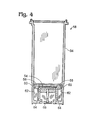
- FIG. 4 is a cross-sectional view of a print cartridge such as that shown in FIG. 2 incorporating a filter and filter carrier according to one embodiment of the present invention.
- FIG. 5 is an isometric view of an exemplary filter and filter carrier according to the present invention.
- FIG. 6 is a cross-sectional view of an exemplary filter and filter carrier according to the present invention along line 6-6 of FIG. 5.
- FIG. 7 is an enlarged cross-sectional view of the filter member according to the present invention.
- The present invention provides a polymeric filter for use in a printer. The polymeric filter is placed in the ink flow path of an inkjet printer and may be used, for example, to reduce or eliminate particulate matter in ink used for mechanical printing.
- FIG. 1 depicts an
exemplary printer 10 suitable for use in implementing a printing system in accordance with one embodiment of the present invention. As shown,printer 10 includes atray 12 for holdingprint media 14, which may be, for example, a sheet of paper.Printer 10 further includes anink supply 16, including one ormore ink containers 30, which provide ink to one ormore print cartridges 18, for example, via aflexible conduit 28. Alternatively, each ofprint cartridges 18 may utilize one or more onboard ink reservoirs (not shown) rather than the remote ink containers shown at 30. It will be appreciated that these onboard ink reservoirs may be refilled with ink so as to enable extended use of the print cartridges. Furthermore,print cartridges 18 may be permanently or removably mounted tocarriage 22. -
Carriage 22 may be of any conventional type, and may employ a codedstrip 32, which may be optically detected by a photodetector (not shown) incarriage 22 for precise positioning of the carriage. The carriage may be moved using a stepper motor (not shown), which may be connected tocarriage 22 by a drive belt, screw drive, or other suitable mechanism. - When a printing operation is initiated,
print media 14 is fed into theprinting area 20 ofprinter 10. Onceprint media 14 is properly positioned,carriage 22 may traverse the print media, for example onslide rod 24, such that the one or more print cartridges may eject ink onto the print media in the proper position.Print media 14 then may be moved incrementally, for example by a conventional stepper motor andfeed rollers 26, so thatcarriage 22 again may traverse the print media, allowing the one or more print cartridges to eject ink onto a new position on the print media. This process may be repeated until the printing operation is complete, at which point the print media may be removed fromprinting area 20. - FIG. 2 shows the exterior of an
exemplary print cartridge 18. As shown,print cartridge 18 includes abody 34, which forms anink chamber 36. A schematic cross-section ofprint cartridge 18 is shown in FIG. 3. As shown,ink chamber 36 typically terminates in one ormore nozzles 44. In some embodiments, the print cartridge may contain plural rows of offset nozzles, although such an arrangement is not shown, for simplicity. - Upon initiation of a printing operation, a signal may be produced from, for example, an electrical connection between
print cartridge 18 andprinter 10. The signal may be sent to a series of ink ejection elements (not shown) and a thin layer of ink withinink chamber 36 may be superheated to provide explosive vaporization and, consequently, cause a droplet of ink to be ejected throughnozzles 44. Other ink ejection mechanisms may also be employed, such as piezoelectric print mechanisms. This process enables selective deposition of ink onprint media 14 to generate text and images. However, since the print cartridge nozzles have relatively small flow areas, thenozzles 44 are susceptible to clogging from contaminant particles from the ink supply and ink cartridge surfaces. This compromises the printing process and limits high throughput printing. - To prevent clogging, a
filter element 54 may be placed in the ink flow path between the ink supply and the print nozzles. The filter may be adapted to prevent particulate matter from reaching and clogging the print cartridge nozzles. -
Filter element 54 is preferably housed within afilter carrier 56, which fits inside theprint cartridge body 34. The filter carrier serves to provide additional structure for the filter material and to create a strong seal between the filter and the cartridge body such that any ink within the print cartridge must pass through the filter before it is delivered tonozzles 44. - In this embodiment, the filter assembly, including the filter element and the filter carrier, is press-fit into the print cartridge body, making a seal between the carrier and the print cartridge body walls due to an interference fit between a
sealing feature 60 on the carrier and the inside ofprint cartridge 18, as discussed below. - As shown in FIG. 4,
filter carrier 56 may be over-molded or insert molded aroundfilter element 54. As shown, in this embodiment,filter carrier 56 may include acarrier lip 60 that flexes inwards after contacting thewall 62 ofcartridge body 34 to form a seal. In this configuration,filter carrier 56 may rest onlandings 64.Standpipe 66 may be open, as shown in this figure, or may provide a trough-like feature for the ink to flow through (not shown). - FIGS. 5, 6, and 7 further illustrate an exemplary embodiment of the filter of the present invention. FIG. 5 is an isometric view of the filter and filter carrier; FIG. 6 is a cross-sectional view of the filter and filter carrier along line 6-6 of FIG. 5; and FIG. 7 is an enlarged cross-sectional view of the filter element. As shown in FIG. 5,
filter carrier 56 preferably includes aresilient lip 60 to retain the carrier in the print cartridge, and may include one or more stiffening and reinforcingmembers 68. Although depicted as rectangular, the filter carrier may be other shapes, such as round. - As shown in FIG. 6, the
carrier 56 is preferably overmolded over thefilter element 54. The carrier material should be chemically stable to withstand prolonged exposure to inkjet inks. The material should also be resistant to deformation when exposed to high temperatures, such as might be present during the assembly of the cartridge, and should retain its strength and resilience. A preferred material for the carrier is a polyetherimide (PEI) resin material, such as made by General Electric Plastics under the trade name Ultem® 1010. The carrier preferably includes aresilient lip 60 which forms a tight seal when installed in the cartridge to prevent ink from flowing around, rather than through, the filter. - FIG. 7 is an enlarged cross-sectional view of the
filter element 54. The filter element preferably comprises aprimary filter material 74, such as discussed below, and abacking layer 72 to provide structure and support for the filter. The backing layer may be on one side of the filter material or on both sides of the filter material; with some filter materials, a backing layer may be unnecessary. The backing layer may be a lightweight plastic such as polypropylene or any other suitable material. As will be appreciated, if a backing material is used, the backing material should have the same or higher tolerance for the corrosive effects of the ink composition being used as the primary filter material, as described in detail below. - The
primary filter material 74 of the present invention is preferably a polymeric material. For the purposes of the present discussion, a polymeric material is a material made of a chemical compound having a high molecular weight and including a number of structural units linked together by covalent bonds. The simple molecules that may become structural units are themselves called monomers. A structural unit is a group of monomers having two or more bonding sites. In a linear polymer, the monomers are connected in a chain arrangement and thus need only have two bonding sites. When the monomers have three bonding sites, a nonlinear, or branched, polymer results. (See, The Concise Columbia Encyclopedia, Columbia University Press (1995). - The use of a suitable polymeric material provides the filter with increased filtration efficiency and higher tolerance for the corrosive effects of certain ink compositions than previously described woven metal filters. Examples of suitable polymeric materials are polysulfone (PSU) and polytetrafluoroethylene (PTFE). A preferred material is an alloy of polysulfone and polyvinylpyrrolidone (PVP), such as produced by Filterite.
- Filters may be assessed under a number of criteria related to the filters' performance and ability to withstand various conditions. In combination, these criteria can be used to define which filter is suitable for a particular use. These characteristics include incoming part cleanliness, filtration efficiency, pressure drop, chemical robustness, thermal robustness, and thickness, each of which is described in further detail below.
- In general, incoming part cleanliness, filtration efficiency, pressure drop and chemical robustness are the more important criteria in determining a filter's ability to perform. Thermal robustness and thickness tend to be dependant upon the particular system being used and may be modified for any given system. Accordingly, when comparing various filter materials, a filter that exhibits superior performance in incoming part cleanliness, filtration efficiency, pressure drop and/or chemical robustness may prove to be more suitable for use even if it exhibits inferior performance in thermal robustness.
- Typically, “incoming part cleanliness” (IPC) is the number of particles of a given size that are given off or “shed” by a square centimeter of the filter during use. For the purposes of the present invention, the IPC of the filter is established by determining the number of 6 um and larger particles that are shed by the filter after exposure to liquid. The IPC may be determined by flushing the filter with a clean isopropyl alcohol solution, collecting the elutant and conducting a particle count on the collected elutant using a liquid particle counter. These particles may have been picked up by the filter during manufacture or handling prior to use. Typical woven metal filters have an approximate IPC of less than 300 shed particles. Filters of the present invention should have an IPC of less than 100 shed particles, preferably less than 75 shed particles, and more preferably less than 50 shed particles.
- The “filtration efficiency” (FE) of a filter is established by determining the percentage of particles of a given size that are removed from the ink by the filter at a given flow rate. For the purposes of the present invention, the FE of the filter is established by determining the percentage of 6 um and larger particles that are removed by the filter at flow rates of between 0 and 10 ml/min. Typical woven metal filters have a FE of approximately 75%. Filters of the present invention should have an FE of greater than 98%, preferably greater than 99%, and more preferably greater than 99.5%.
- The “pressure drop” (PD) of a filter is determined by measuring the difference in pressure on either side of the filter as a fluid is pushed through the filter. The PD may be dependant upon several factors including the flow rate of the fluid, the viscosity of the fluid, and the area of the filter. For the purposes discussion, the PD referred to herein is the pressure loss through one square centimeter of filter at a flow rate of 5 ml/min of Isopropyl alcohol. Typical woven metal filters have a PD of approximately 1″ H 2O. Filters of the present invention may have a pressure drop of between less than 1.5″ H2O, preferably less than 1″ H2O, and most preferably less than 0.5″ H2O.
- The “chemical robustness” (CR) of a filter is established by determining whether the filter retains all the physical properties and continues to meet specifications after prolonged exposure to ink. Furthermore, the filter should not leach substances into the ink that change the properties of the ink. In short, the filters of the present invention are typically chemically inert when subjected to the hostile conditions in the print cartridge created by the ink. As will be appreciated, a filter that is able to withstand a wider range of conditions is greatly desired as it enables the use of a wider range of ink compositions.
- For the purposes of the present discussion, the term “corrosive” is used to describe ink materials that are capable of chemically degrading various components typically encountered in conventional ink delivery systems (especially plastic parts). Corrosive agents in the ink formulations may include one or more organic solvents, which are employed as ink vehicles or humectants, as well as reactive components and other compounds (depending on the ink products under consideration.)
- Various ink compositions and their components are described in, for example, commonly assigned U.S. Pat. No. 6,196,669 to Harvey et al. The polymeric filters of the present invention are typically inert when subjected to the ink compositions described in U.S. Pat. No. 6,196,669, even for prolonged periods of time.
- The exemplary ink compositions described in U.S. Pat. No. 6,196,669 typically contain at least one coloring agent. This coloring agent may be either a black or color dye. Exemplary black dyes are listed in U.S. Pat. No. 4,963,189 to Hindagolla. Multiple color dye materials are described in the Color Index, Vol. 4, 3rd ed., published by The Society of Dyers and Colourists, Yorkshire, England (1971). As used in U.S. Pat. No. 6,196,669, the term “coloring agent” encompasses pigment dispersions that involve a water-insoluble colorant (namely, a pigment) that is rendered soluble through association with a dispersant (e.g. an acrylic compound). Those of skill in the art will know specific pigments that may be employed to produce pigment dispersions. Typically, the ink compositions of interest will contain about 2-7% by weight total coloring agent therein (e.g. whether a single coloring agent or combined coloring agents are used). However, the amount of coloring agent to be employed may be varied as needed, depending on the ultimate purpose for which the ink composition is intended and the other ingredients in the ink.
- The exemplary ink compositions described in U.S. Pat. No. 6,196,669 also may include an ink vehicle. The ink vehicle functions as a carrier medium and main solvent for the other ink ingredients. Many different materials may be used as the ink vehicle, and the present invention is not limited to any particular products for this purpose. A typical ink vehicle may include water combined with other components including organic solvents. These organic solvents may include, but are not limited to, 2-pyrrolidone, 1,5-pentanediol, N-methyl pyrrolidone, 2-propanol, ethoxylated glycerol, 2-ethyl-2-hydroxymethyl-1,3-propanediol, cyclohexanol, and/or other materials known in the art for solvent and/or humectant purposes. Such materials are volatile and may be corrosive as defined above. These compounds may be used in various combinations. Typically, the ink formulations will contain about 70-80% by weight total combined ink vehicle.
- The exemplary ink compositions described in U.S. Pat. No. 6,196,669 may also include a number of optional ingredients in varying amounts. For example, an optional biocide may be added to prevent any microbial growth in the final ink product. Exemplary biocides suitable for this purpose include proprietary products sold under the trademarks PROXEL GXL by Imperial Chemical Industries of Manchester, England; UCARCID by Union Carbide of Danbury, Conn. (USA); and NUOSEPT by Huls America, Inc. of Piscataway, N.J. (USA). If a biocide is used, the final ink composition will typically include about 0.05-0.5% by weight biocide, with about 0.30% by weight being typical.
- Another optional ingredient described in U.S. Pat. No. 6,196,669 may involve one or more buffering agents. The use of a selected buffering agent or multiple (combined) buffering agents is intended to stabilize the pH of the ink formulations, if needed or desired. The optimum pH of the ink compositions may range from approximately 4-9.5. Exemplary buffering agents suitable for this purpose include sodium borate, boric acid, and phosphate buffering materials known in the art for pH control. The selection of any particular buffering agents, and the amount of buffering agents to be used (as well as the decision to use buffering agents in general), may be made in accordance with preliminary pilot studies on the particular ink compositions of concern. Additional ingredients (e.g. surfactants) may also be present in the ink compositions, if needed or desired.
- Polymeric filters of the present invention are generally resistant to the corrosive effects of ink and are able to maintain structural integrity and resist chemical deterioration from ink for at least 5 years. Thus, filter 54 may be used in printing systems that utilize ink materials that contain volatile and/or corrosive components including reactive dyes and organic solvents. Moreover, because the polymeric filter of the present invention has a higher tolerance for the corrosive effects of ink than the previously-described woven metal filters, many different ink formulations may be used in connection with the present invention, thus allowing for the manufacture of a single filter type for use in a wide variety of printing applications.
- For the purposes of the present invention, the “thermal robustness” (TR) of the filter is established by determining whether the filter retains all the physical properties and continues to meet the above specifications after exposure to the high temperatures required during processing. Filters of the present invention generally retain thermal robustness at or below 80° C., preferably at or below 90° C., and more preferably at or below 100° C.
- For the purposes of the present invention, the “thickness” refers to the thickness of the filter media and any required backer materials, shown in FIG. 7. As will be understood, the thickness may be dependent upon the design of the print cartridge in which the filter is used. Thus, without wishing to be limited, a typical filter of the present invention will have a thickness of less than 0.030″, preferably less than 0.020″, and more preferably less than 0.010″, however filters having a thickness well outside of this range are contemplated by the present invention.
- Due to its high level of incoming part cleanliness, increased filtration efficiency, reduced pressure drop, and increased chemical robustness, the polymeric filter of the present invention is capable not only of filtering particles from the ink flow, but also of surviving a variety of hostile conditions created within the ink cartridge. As will be appreciated, these conditions can change depending on the specific ink composition used. Thus, the present invention provides a filter capable of withstanding a wide range of conditions obviating or reducing the need to manufacture and use different filters for different ink compositions.
- Accordingly, while the present invention has been shown and described with reference to the foregoing preferred embodiments, it will be apparent to those skilled in the art that other changes in form and detail may be made therein without departing from the spirit and scope of the invention as defined in the appended claims. For example, while many of the features of the present invention have been described by reference to figures and descriptions suitable for ink jet printers and their associated cartridges, the filter of the present invention is suitable for any printing system in which it is desirable to filter particulate matter in the ink supply. Thus additional printers and print cartridges are contemplated by the present invention.
- The subject matter of the inventions includes all novel and non-obvious combinations and subcombinations of the various elements, features, functions and/or properties disclosed herein. Similarly, where the claims recite “a” or “a first” element or the equivalent thereof, such claims should be understood to include incorporation of one or more such elements, neither requiring nor excluding two or more such elements. It is believed that the following claims particularly point out certain combinations and subcombinations that are directed to one of the disclosed inventions and are novel and non-obvious. Inventions embodied in other combinations and subcombinations of features, functions, elements and/or properties may be claimed through amendment of the present claims or presentation of new claims in this or a related application. Such amended or new claims, whether they are directed to a different invention or directed to the same invention, whether different, broader, narrower or equal in scope to the original claims, are also regarded as included within the subject matter of the inventions of the present disclosure.
Claims (24)
Priority Applications (6)
| Application Number | Priority Date | Filing Date | Title |
|---|---|---|---|
| US10/128,397 US6986571B2 (en) | 2002-04-23 | 2002-04-23 | Filter for a print cartridge |
| TW092106383A TWI271321B (en) | 2002-04-23 | 2003-03-21 | Filter for a print cartridge |
| EP03252208A EP1361067B1 (en) | 2002-04-23 | 2003-04-08 | Filter for a print cartridge |
| DE60316067T DE60316067T2 (en) | 2002-04-23 | 2003-04-08 | Filter for a print cartridge |
| JP2003113585A JP2003312007A (en) | 2002-04-23 | 2003-04-18 | Ink filter for inkjet cartridge, and printing cartridge |
| CN03128469.8A CN1283467C (en) | 2002-04-23 | 2003-04-23 | Filter for printing ink cartridge |
Applications Claiming Priority (1)
| Application Number | Priority Date | Filing Date | Title |
|---|---|---|---|
| US10/128,397 US6986571B2 (en) | 2002-04-23 | 2002-04-23 | Filter for a print cartridge |
Publications (2)
| Publication Number | Publication Date |
|---|---|
| US20030197767A1 true US20030197767A1 (en) | 2003-10-23 |
| US6986571B2 US6986571B2 (en) | 2006-01-17 |
Family
ID=29215459
Family Applications (1)
| Application Number | Title | Priority Date | Filing Date |
|---|---|---|---|
| US10/128,397 Expired - Lifetime US6986571B2 (en) | 2002-04-23 | 2002-04-23 | Filter for a print cartridge |
Country Status (6)
| Country | Link |
|---|---|
| US (1) | US6986571B2 (en) |
| EP (1) | EP1361067B1 (en) |
| JP (1) | JP2003312007A (en) |
| CN (1) | CN1283467C (en) |
| DE (1) | DE60316067T2 (en) |
| TW (1) | TWI271321B (en) |
Cited By (17)
| Publication number | Priority date | Publication date | Assignee | Title |
|---|---|---|---|---|
| US20050110820A1 (en) * | 2003-11-26 | 2005-05-26 | Fuji Xerox Co., Ltd. | Systems and methods for dissipating heat into a fluid ejector carriage device |
| US20050110828A1 (en) * | 2003-11-26 | 2005-05-26 | Fuji Xerox Co., Ltd. | Systems and method for dissipating heat from a fluid ejector carriage |
| US20070091153A1 (en) * | 2005-10-25 | 2007-04-26 | Shields James P | Biocidal print system components |
| US20070139498A1 (en) * | 2005-12-16 | 2007-06-21 | Brother Kogyo Kabushiki Kaisha | Ink-jet head and method for manufacturing the same |
| US20090213199A1 (en) * | 2008-02-21 | 2009-08-27 | Seiko Epson Corporation | Liquid ejecting head, method of manufacturing the same, and liquid ejecting apparatus |
| US20090225142A1 (en) * | 2008-03-06 | 2009-09-10 | Seiko Epson Corporation | Liquid ejection head, method for manufactuirng the same, and liquid ejecting apparatus |
| US20100187614A1 (en) * | 2004-01-22 | 2010-07-29 | International Business Machines Corporation | Selective nitridation of gate oxides |
| US20110261125A1 (en) * | 2010-04-27 | 2011-10-27 | Yonglin Xie | Continuous printhead including polymeric filter |
| US20120098898A1 (en) * | 2010-10-20 | 2012-04-26 | Xerox Corporation | Method and system for ink delivery and purged ink recovery in an inkjet printer |
| US20120293592A1 (en) * | 2011-05-16 | 2012-11-22 | Silverbrook Research Pty Ltd | Ink distribution system having gas venting |
| US8439494B2 (en) | 2007-11-02 | 2013-05-14 | Seiko Epson Corporation | Liquid ejecting head, method for making the same, and liquid ejecting apparatus |
| US8636346B2 (en) | 2010-05-17 | 2014-01-28 | Zamtec Ltd | Multi-path valve for printhead |
| US8845083B2 (en) | 2010-05-17 | 2014-09-30 | Memjet Technology Ltd. | Inkjet printer having dual valve arrangement |
| US8876267B2 (en) | 2009-07-31 | 2014-11-04 | Memjet Technology Ltd. | Printing system with multiple printheads each supplied by multiple conduits |
| US9150026B1 (en) * | 2014-03-31 | 2015-10-06 | Brother Kogyo Kabushiki Kaisha | Liquid jetting apparatus |
| US20170197428A1 (en) * | 2016-01-13 | 2017-07-13 | Océ Holding B.V. | Filter device for filtering ink and ink supply system for printing apparatus |
| WO2022032109A1 (en) * | 2020-08-06 | 2022-02-10 | The Regents Of The University Of Michigan | Electrohydrodynamic jet printed photonic devices |
Families Citing this family (10)
| Publication number | Priority date | Publication date | Assignee | Title |
|---|---|---|---|---|
| US7044591B2 (en) * | 2002-09-25 | 2006-05-16 | Brother Kogya Kabushiki Kaisha | Ink-jet head, filter assembly used for manufacturing the ink-jet head, and method for manufacturing the ink-jet head using the filter assembly |
| US7448742B2 (en) * | 2004-09-14 | 2008-11-11 | Shaw Raymond D | Reusable cartridge for inkjet printer |
| KR100612450B1 (en) * | 2004-10-14 | 2006-08-16 | 삼성전자주식회사 | Ink cartridge for the wide array type head |
| JP4715247B2 (en) * | 2005-03-10 | 2011-07-06 | 富士ゼロックス株式会社 | Filter device and droplet discharge device |
| US8114268B2 (en) * | 2005-12-30 | 2012-02-14 | Medtronic Minimed, Inc. | Method and system for remedying sensor malfunctions detected by electrochemical impedance spectroscopy |
| JP2007203623A (en) * | 2006-02-02 | 2007-08-16 | Canon Inc | Inkjet recording head and its manufacturing method |
| US8556399B2 (en) * | 2008-10-30 | 2013-10-15 | Hewlett-Packard Development Company, L.P. | Fluid interconnect for fluid ejection system |
| EP2828081B1 (en) * | 2012-07-24 | 2019-10-09 | Hewlett-Packard Company, L.P. | Fluid ejection device with particle tolerant thin-film extension |
| JP2014208422A (en) * | 2012-08-08 | 2014-11-06 | セイコーエプソン株式会社 | Liquid storage container and liquid supply system |
| JP6078301B2 (en) * | 2012-11-07 | 2017-02-08 | 株式会社ミマキエンジニアリング | Damper device and inkjet printer |
Citations (3)
| Publication number | Priority date | Publication date | Assignee | Title |
|---|---|---|---|---|
| US4995977A (en) * | 1988-02-09 | 1991-02-26 | Gkss- Forschungszentrum Geesthacht Gmbh | Apparatus for filtering and separating flow medium |
| US6120140A (en) * | 1994-05-20 | 2000-09-19 | Canon Kabushiki Kaisha | Ink supplying apparatus and ink recording apparatus having same |
| US6702436B2 (en) * | 2002-01-30 | 2004-03-09 | Hewlett-Packard Development Company, L.P. | Fluid ejection cartridge including a compliant filter |
Family Cites Families (12)
| Publication number | Priority date | Publication date | Assignee | Title |
|---|---|---|---|---|
| DE4000825A1 (en) * | 1990-01-13 | 1990-05-03 | Horst Dipl Chem Dr Perl | Hydrophilic membrane filters of polysulphone for micro-filtration - obtd. from solns. of polysulphone in N-methyl:pyrrolidone and polyethylene glycol, with addn. of polyvinyl-pyrrolidone |
| DE4007383C2 (en) * | 1990-03-08 | 1998-10-29 | Seitz Filter Werke | Manufacture of hydrophilic microfiltration membranes from polysulfones |
| US5610645A (en) * | 1993-04-30 | 1997-03-11 | Tektronix, Inc. | Ink jet head with channel filter |
| US5657065A (en) * | 1994-01-03 | 1997-08-12 | Xerox Corporation | Porous medium for ink delivery systems |
| DE4422158A1 (en) * | 1994-06-24 | 1996-01-04 | Hoechst Ag | Homogeneous polymer alloys based on sulfonated, aromatic polyether ketones |
| JPH09295406A (en) | 1996-05-02 | 1997-11-18 | Canon Inc | Ink tank, its production and ink jet printing cartridge |
| CA2274077C (en) | 1997-01-21 | 2003-05-13 | Gore Enterprise Holdings, Inc. | Ink filter element for printers |
| US6234622B1 (en) | 1997-04-30 | 2001-05-22 | Hewlett-Packard Company | Ink delivery system that utilizes a separate insertable filter carrier |
| US6007176A (en) * | 1998-05-05 | 1999-12-28 | Lexmark International, Inc. | Passive cooling arrangement for a thermal ink jet printer |
| US6086195A (en) * | 1998-09-24 | 2000-07-11 | Hewlett-Packard Company | Filter for an inkjet printhead |
| JP2001199082A (en) * | 1999-10-08 | 2001-07-24 | Seiko Epson Corp | Ink cartridge, ink jet recording apparatus and method for fitting ink cartridge |
| JP2002102619A (en) * | 2000-09-29 | 2002-04-09 | Nok Corp | Method and apparatus for manufacturing filter gasket |
-
2002
- 2002-04-23 US US10/128,397 patent/US6986571B2/en not_active Expired - Lifetime
-
2003
- 2003-03-21 TW TW092106383A patent/TWI271321B/en not_active IP Right Cessation
- 2003-04-08 EP EP03252208A patent/EP1361067B1/en not_active Expired - Fee Related
- 2003-04-08 DE DE60316067T patent/DE60316067T2/en not_active Expired - Lifetime
- 2003-04-18 JP JP2003113585A patent/JP2003312007A/en not_active Withdrawn
- 2003-04-23 CN CN03128469.8A patent/CN1283467C/en not_active Expired - Fee Related
Patent Citations (3)
| Publication number | Priority date | Publication date | Assignee | Title |
|---|---|---|---|---|
| US4995977A (en) * | 1988-02-09 | 1991-02-26 | Gkss- Forschungszentrum Geesthacht Gmbh | Apparatus for filtering and separating flow medium |
| US6120140A (en) * | 1994-05-20 | 2000-09-19 | Canon Kabushiki Kaisha | Ink supplying apparatus and ink recording apparatus having same |
| US6702436B2 (en) * | 2002-01-30 | 2004-03-09 | Hewlett-Packard Development Company, L.P. | Fluid ejection cartridge including a compliant filter |
Cited By (35)
| Publication number | Priority date | Publication date | Assignee | Title |
|---|---|---|---|---|
| US20050110828A1 (en) * | 2003-11-26 | 2005-05-26 | Fuji Xerox Co., Ltd. | Systems and method for dissipating heat from a fluid ejector carriage |
| US7192116B2 (en) * | 2003-11-26 | 2007-03-20 | Fuji Xerox Co., Ltd. | Systems and methods for dissipating heat from a fluid ejector carriage |
| US7261389B2 (en) * | 2003-11-26 | 2007-08-28 | Fuji Xerox Co., Ltd. | Systems and methods for dissipating heat into a fluid ejector carriage device |
| US20050110820A1 (en) * | 2003-11-26 | 2005-05-26 | Fuji Xerox Co., Ltd. | Systems and methods for dissipating heat into a fluid ejector carriage device |
| US20100187614A1 (en) * | 2004-01-22 | 2010-07-29 | International Business Machines Corporation | Selective nitridation of gate oxides |
| US20070091153A1 (en) * | 2005-10-25 | 2007-04-26 | Shields James P | Biocidal print system components |
| WO2007050786A1 (en) * | 2005-10-25 | 2007-05-03 | Hewlett-Packard Development Company, L.P. | Biocidal print system components |
| US20070139498A1 (en) * | 2005-12-16 | 2007-06-21 | Brother Kogyo Kabushiki Kaisha | Ink-jet head and method for manufacturing the same |
| US7922311B2 (en) * | 2005-12-16 | 2011-04-12 | Brother Kogyo Kabushiki Kaisha | Ink-jet head and method of manufacturing the same |
| US8439494B2 (en) | 2007-11-02 | 2013-05-14 | Seiko Epson Corporation | Liquid ejecting head, method for making the same, and liquid ejecting apparatus |
| US8240833B2 (en) * | 2008-02-21 | 2012-08-14 | Seiko Epson Corporation | Liquid ejecting head, method of manufacturing the same, and liquid ejecting apparatus |
| US20090213199A1 (en) * | 2008-02-21 | 2009-08-27 | Seiko Epson Corporation | Liquid ejecting head, method of manufacturing the same, and liquid ejecting apparatus |
| US20090225142A1 (en) * | 2008-03-06 | 2009-09-10 | Seiko Epson Corporation | Liquid ejection head, method for manufactuirng the same, and liquid ejecting apparatus |
| US8876267B2 (en) | 2009-07-31 | 2014-11-04 | Memjet Technology Ltd. | Printing system with multiple printheads each supplied by multiple conduits |
| US20110261125A1 (en) * | 2010-04-27 | 2011-10-27 | Yonglin Xie | Continuous printhead including polymeric filter |
| US8562120B2 (en) * | 2010-04-27 | 2013-10-22 | Eastman Kodak Company | Continuous printhead including polymeric filter |
| US8807725B2 (en) | 2010-05-17 | 2014-08-19 | Memjet Technology Ltd. | System for priming and de-priming printhead |
| US8845083B2 (en) | 2010-05-17 | 2014-09-30 | Memjet Technology Ltd. | Inkjet printer having dual valve arrangement |
| US8636346B2 (en) | 2010-05-17 | 2014-01-28 | Zamtec Ltd | Multi-path valve for printhead |
| US8641177B2 (en) | 2010-05-17 | 2014-02-04 | Zamtec Ltd | Diaphragm valve for printhead |
| US8662647B2 (en) | 2010-05-17 | 2014-03-04 | Zamtec Ltd | Rotary valve for printhead |
| US8733908B2 (en) | 2010-05-17 | 2014-05-27 | Zamtec Ltd | Printing system having valved ink and gas distribution for printhead |
| US8777388B2 (en) | 2010-05-17 | 2014-07-15 | Zamtec Ltd | Fluid distribution system having four-way valve |
| US8794748B2 (en) | 2010-05-17 | 2014-08-05 | Memjet Technology Ltd. | Multi-channel valve arrangement for printhead |
| US8991955B2 (en) | 2010-05-17 | 2015-03-31 | Memjet Technology Ltd. | Inkjet printer having bypass line |
| US8967746B2 (en) | 2010-05-17 | 2015-03-03 | Memjet Technology Ltd. | Inkjet printer configured for printhead priming and depriming |
| US8882247B2 (en) | 2010-05-17 | 2014-11-11 | Memjet Technology Ltd. | Fluid distribution system having multi-path valve for gas venting |
| US20120098898A1 (en) * | 2010-10-20 | 2012-04-26 | Xerox Corporation | Method and system for ink delivery and purged ink recovery in an inkjet printer |
| US8550612B2 (en) * | 2010-10-20 | 2013-10-08 | Xerox Corporation | Method and system for ink delivery and purged ink recovery in an inkjet printer |
| US20120293592A1 (en) * | 2011-05-16 | 2012-11-22 | Silverbrook Research Pty Ltd | Ink distribution system having gas venting |
| US9150026B1 (en) * | 2014-03-31 | 2015-10-06 | Brother Kogyo Kabushiki Kaisha | Liquid jetting apparatus |
| US20170197428A1 (en) * | 2016-01-13 | 2017-07-13 | Océ Holding B.V. | Filter device for filtering ink and ink supply system for printing apparatus |
| US10046570B2 (en) * | 2016-01-13 | 2018-08-14 | Océ Holding B.V. | Filter device for filtering ink and ink supply system for printing apparatus |
| WO2022032109A1 (en) * | 2020-08-06 | 2022-02-10 | The Regents Of The University Of Michigan | Electrohydrodynamic jet printed photonic devices |
| US11712889B2 (en) | 2020-08-06 | 2023-08-01 | The Regents Of The University Of Michigan | Electrohydrodynamic jet printed photonic devices |
Also Published As
| Publication number | Publication date |
|---|---|
| TW200404680A (en) | 2004-04-01 |
| EP1361067B1 (en) | 2007-09-05 |
| JP2003312007A (en) | 2003-11-06 |
| EP1361067A1 (en) | 2003-11-12 |
| DE60316067T2 (en) | 2008-04-30 |
| TWI271321B (en) | 2007-01-21 |
| DE60316067D1 (en) | 2007-10-18 |
| US6986571B2 (en) | 2006-01-17 |
| CN1453135A (en) | 2003-11-05 |
| CN1283467C (en) | 2006-11-08 |
Similar Documents
| Publication | Publication Date | Title |
|---|---|---|
| US6986571B2 (en) | Filter for a print cartridge | |
| JP6414659B2 (en) | Ink jet recording ink, ink container, ink jet recording apparatus | |
| KR20070011454A (en) | Recording ink, ink cartridge, ink record, inkjet recording apparatus and inkjet recording process | |
| US10286666B2 (en) | Ink discharge device and ink discharge method | |
| WO2007148823A1 (en) | Recording head, recording unit, ink jet recorder, ink jet recording method, and ink set | |
| US20050229811A1 (en) | Ink-jet recording ink, ink-jet recording method, and ink-jet recording apparatus | |
| WO2007148824A1 (en) | Ink set, ink cartridge set, ink jet recording method, recording unit and ink jet recording apparatus | |
| US5713991A (en) | Recording apparatus and ink employing biodegradable substance | |
| US7247198B2 (en) | Water base for ink-jet recording and ink-jet recording method | |
| JP2005320531A (en) | Recording ink, ink cartridge, ink record, inkjet recorder and inkjet recording method | |
| JP2013059892A (en) | Inkjet recording apparatus | |
| EP0614952A2 (en) | Ink, and ink-jet recording method and apparatus employing the ink | |
| US9944084B2 (en) | Ink jet recording method and ink jet recording apparatus | |
| US10828897B2 (en) | Ink jet recording method and ink jet recording apparatus | |
| EP3339382B1 (en) | Ink, ink cartridge, and ink jet recording method | |
| JP2007253391A (en) | Maintenance method for inkjet recorder | |
| US11827034B2 (en) | Ink jet recording method and ink jet recording apparatus | |
| JP2017177593A (en) | Ink tank cap, ink tank and inkjet recording device | |
| JP7091158B2 (en) | Inkjet recording method and inkjet recording device | |
| JP3253644B2 (en) | Oil-based ink container for electric field control type ink jet printer, oily ink circulation member for electric field control type ink jet printer, and method for maintaining specific resistance of ink at 1 × 10 6 Ω · cm or more | |
| JP2008127507A (en) | Recording liquid, recording method and recording liquid cartridge | |
| GB2622590A (en) | Filter for ink | |
| JP2024032367A (en) | Water-based inkjet ink composition and inkjet recording method | |
| JP5659922B2 (en) | Water-based ink for ink jet recording, ink cartridge, ink jet recording method and ink jet recording apparatus | |
| JP2004188636A (en) | Ink storage part, ink, inkjet recording apparatus, and inkjet recording method |
Legal Events
| Date | Code | Title | Description |
|---|---|---|---|
| AS | Assignment |
Owner name: HEWLETT-PACKARD COMPANY, COLORADO Free format text: ASSIGNMENT OF ASSIGNORS INTEREST;ASSIGNORS:DUDENHOEFER, CHRISTIE;WEIBEZAHN, KARL STEFAN;WATTS, GARY J.;REEL/FRAME:013759/0467 Effective date: 20020423 |
|
| AS | Assignment |
Owner name: HEWLETT-PACKARD COMPANY, COLORADO Free format text: ASSIGNMENT OF ASSIGNORS INTEREST;ASSIGNORS:DUDENHOEFER, CHRISTIE;WEIBEZAHN, KARL STEFAN;WATTS, GARY J.;REEL/FRAME:013626/0781 Effective date: 20020423 |
|
| AS | Assignment |
Owner name: HEWLETT-PACKARD DEVELOPMENT COMPANY, L.P., COLORAD Free format text: ASSIGNMENT OF ASSIGNORS INTEREST;ASSIGNOR:HEWLETT-PACKARD COMPANY;REEL/FRAME:013776/0928 Effective date: 20030131 Owner name: HEWLETT-PACKARD DEVELOPMENT COMPANY, L.P.,COLORADO Free format text: ASSIGNMENT OF ASSIGNORS INTEREST;ASSIGNOR:HEWLETT-PACKARD COMPANY;REEL/FRAME:013776/0928 Effective date: 20030131 |
|
| STCF | Information on status: patent grant |
Free format text: PATENTED CASE |
|
| CC | Certificate of correction | ||
| FPAY | Fee payment |
Year of fee payment: 4 |
|
| FPAY | Fee payment |
Year of fee payment: 8 |
|
| FPAY | Fee payment |
Year of fee payment: 12 |