US20030191400A1 - System for determining values of hemodynamic parameters for a lesioned blood vessel, processor therefor, and method therefor - Google Patents
System for determining values of hemodynamic parameters for a lesioned blood vessel, processor therefor, and method therefor Download PDFInfo
- Publication number
- US20030191400A1 US20030191400A1 US10/412,335 US41233503A US2003191400A1 US 20030191400 A1 US20030191400 A1 US 20030191400A1 US 41233503 A US41233503 A US 41233503A US 2003191400 A1 US2003191400 A1 US 2003191400A1
- Authority
- US
- United States
- Prior art keywords
- ptc
- bpg
- pressure pulse
- lesioned
- blood vessel
- Prior art date
- Legal status (The legal status is an assumption and is not a legal conclusion. Google has not performed a legal analysis and makes no representation as to the accuracy of the status listed.)
- Abandoned
Links
- 0 C*C[N+](C)(C)[O-] Chemical compound C*C[N+](C)(C)[O-] 0.000 description 1
Images


Classifications
-
- A—HUMAN NECESSITIES
- A61—MEDICAL OR VETERINARY SCIENCE; HYGIENE
- A61B—DIAGNOSIS; SURGERY; IDENTIFICATION
- A61B5/00—Measuring for diagnostic purposes; Identification of persons
- A61B5/02—Detecting, measuring or recording pulse, heart rate, blood pressure or blood flow; Combined pulse/heart-rate/blood pressure determination; Evaluating a cardiovascular condition not otherwise provided for, e.g. using combinations of techniques provided for in this group with electrocardiography or electroauscultation; Heart catheters for measuring blood pressure
- A61B5/021—Measuring pressure in heart or blood vessels
- A61B5/02108—Measuring pressure in heart or blood vessels from analysis of pulse wave characteristics
- A61B5/02125—Measuring pressure in heart or blood vessels from analysis of pulse wave characteristics of pulse wave propagation time
-
- A—HUMAN NECESSITIES
- A61—MEDICAL OR VETERINARY SCIENCE; HYGIENE
- A61B—DIAGNOSIS; SURGERY; IDENTIFICATION
- A61B5/00—Measuring for diagnostic purposes; Identification of persons
- A61B5/02—Detecting, measuring or recording pulse, heart rate, blood pressure or blood flow; Combined pulse/heart-rate/blood pressure determination; Evaluating a cardiovascular condition not otherwise provided for, e.g. using combinations of techniques provided for in this group with electrocardiography or electroauscultation; Heart catheters for measuring blood pressure
- A61B5/021—Measuring pressure in heart or blood vessels
- A61B5/0215—Measuring pressure in heart or blood vessels by means inserted into the body
Definitions
- the invention relates to determining values of hemodynamic parameters for a lesioned blood vessel.
- Stroke volume pumping by a left ventricle into its adjacent proximal aortic root causes the pressure of the root segment to rise and its wall to distend because it is already filled with blood, thereby creating a high pressure wave which is transmitted into the arteries.
- the morphology of the aortic pressure pulse corresponds to the three phases of the pressure pulse as follows: Phase I is known as the anacrotic rise occurring during early systole and correlating with the inotropic component, the gradient, and height of the anacrotic rise, and anacrotic notch being related to the rate of acceleration of blood.
- Phase II appears as a rounded shoulder by virtue of the continued ejection of stroke volume from the left ventricle, displacement of blood, and distension of the arterial walls which produce the rounded appearance.
- Phase III appears as a descending limb due to diastolic run-off of blood. This part of the curve normally begins with a dicrotic notch as affected by blood running against the closing aortic valve separating systole from diastole.
- a decrease in arterial distensibility occurs with aging and in hypertension, but is most apparent in generalized arteriosclerosis.
- a decrease in arterial distensibility causes an increase in pulse wave velocity which in turn results in the early return of reflected waves from peripheral sites.
- the present invention is based on the premise that quantification of the change in shape of dicrotic notches of so-called distal pressure pulses acquired distal to a lesioned section of a lesioned blood vessel relative to dicrotic notches of so-called proximal pressure pulses acquired proximal thereto can yield clinically important hemodynamic information regarding the lesioned section itself and/or the vascular bed fed by the lesioned blood vessel.
- the basic hemodynamic parameter envisaged by the present invention is a so-called Pulse Transmission Coefficient (PTC) index believed to be indicative of the cumulative effects of a lesioned section of a lesioned blood vessel and the health of the vascular bed fed thereby.
- PTC Pulse Transmission Coefficient
- PTC values can be determined based on pressure waveforms containing a series of pressure pulses acquired at rest or hyperemia as induced by the administration of a suitable vasodilatation medicament, for example, adenosine. PTC values can be determined for both single lesioned and multi-lesioned blood vessels.
- non-hyperemic PTC values for a lesioned blood vessel are described in detail hereinbelow Whilst PTC values are believed to have clinical significance in their own right, non-hyperemic PTC values together with Base Pressure Gradients (BPGs) are acquired at rest by definition, can be employed for calculating non-hyperemic substitutes to the clinically accepted Fractional Flow Reserve (FFR) and Coronary Flow Reserve (CFR) indices with similar cutoff values, namely, ⁇ 0.75 and ⁇ 2, respectively, being indicative of the need for intervention.
- FFR Fractional Flow Reserve
- CFR Coronary Flow Reserve
- the non-hyperemic FFR substitute is termed Lesion Severity Index (LSI). LSI values can be determined for the single lesion of a single lesioned blood vessel or for each lesion of a multi-lesioned blood vessel.
- a vascular bed can be considered analogous to a parallel RC circuit whereby a PTC value for a lesioned blood vessel can be determined to yield a RC time constant indicative of the health of the vascular bed fed thereby
- FIG. 1 is a block diagram of a system for determining values of hemodynamic parameters for a lesioned blood vessel in accordance with the present invention
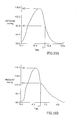
- FIG. 2 is a graph showing an exemplary proximal pressure waveform acquired proximal to a lesioned section of a lesioned blood vessel;
- FIG. 3 is a graph showing an exemplary distal pressure waveform acquired distal to a non-severely lesioned section of a lesioned blood vessel
- FIG. 4 is a graph showing an exemplary distal pressure waveform acquired distal to a severely lesioned section of a lesioned blood vessel
- FIG. 5 showing an exemplary measured pressure pulse P(t) and its low pass filtered derivative Plow(t);
- FIG. 7 is a pictorial representation showing the area of a dicrotic notch for determining the value of a PTC(A) index in accordance with the present invention
- FIG. 8 is a pictorial representation showing the approximation of the area of the dicrotic notch of FIG. 7 to that of a scalene triangle;
- FIG. 9A is a graphical representation showing the area of the leading portion of a distal pressure pulse relative to its entire area for use in determining the value of a PTC(B) index in accordance with the present invention
- FIG. 9B is a graphical representation showing the area of the leading portion of a proximal pressure pulse relative to its entire area for use in determining the value of a PTC(B) index in accordance with the present invention
- FIG. 10A is a graphical representation showing the height of the dicrotic notch of a distal pressure pulse relative to its maximum height for use in determining the value of a PTC(H) index in accordance with the present invention
- FIG. 10B is a graphical representation showing the height of the dicrotic notch of a proximal pressure pulse relative to its maximum height for use in determining the value of a PTC(H) index in accordance with the present invention
- FIG. 11 is a graph plotting LSI values against FFR values for a clinical study of 92 human patients.
- FIG. 12 is a graph plotting non-hyperemic CFR values against true CFR values for a clinical study of 29 human patients.
- FIG. 1 shows a system 1 for determining values of hemodynamic parameters for a lesioned blood vessel 2 having one or more lesions 3 .
- the system 1 includes a general purpose digital computer 4 and intravascular pressure measurement apparatus 6 for acquiring pressure measurements at different locations along the blood vessel 2 .
- the pressure measurements are typically acquired in the form of a pressure waveform of a series of consecutive pressure pulses.
- the computer 4 includes a processor 7 programmed to determine values of hemodynamic parameters for the blood vessel 2 , system memory 8 , nonvolatile storage 9 , a user interface 11 , and a communication interface 12 .
- the constitution of each of these elements is well known and each performs its conventional function as known in the art and accordingly will not be described in greater detail.
- system memory 8 and the non-volatile storage 9 are employed to store a working copy and a permanent copy of the programming instructions implementing the present invention.
- the permanent copy of the programming instructions to practice the present invention may be loaded into the non-volatile storage 9 in the factory, or in the field, through communication interface 12 , or through distribution medium 13 . Any one of a number of recordable medium such as tapes, CD-ROM, DVD and so forth may be employed to store the programming instructions for distribution purposes.
- the intravascular pressure measurement apparatus 6 includes a guiding catheter 14 connected to a fluid filled pressure transducer 16 deployed outside of a patient's body at position A for continuously acquiring aortic pressure for use as a baseline for correcting pressure measurements to compensate for various factors, for example, physiological changes in pressure, breathing, patient movement, and the like, which may influence intravascular pressure measurements since they are not acquired simultaneously.
- An exemplary guiding catheter 14 is the Ascent JL4 catheter commercially available from Medtronic, USA whilst an exemplary fluid filled pressure transducer 16 is commercially available from Biometrix, Jerusalem, Israel.
- the intravascular pressure measurement apparatus 6 also includes a pressure guide wire 17 with a pressure transducer 18 at its tip for acquiring pressure measurements along the blood vessel.
- the pressure transducer 18 is connected to a signal conditioning device 19 .
- An exemplary pressure guide wire 17 is the PressureWire® pressure guide wire commercially available from Radi Medical Systems, Uppsala, Sweden whilst an exemplary signal conditioning device 19 is also commercially available from Radi Medical Systems.
- FIG. 2 depicts an exemplary proximal rest pressure waveform acquired proximal to a lesioned section of a lesioned blood vessel, the pressure waveform including a series of consecutive pressure pulses each having a dicrotic notch which typically continues in the distal rest pressure waveform in the case of a non-severely lesioned blood vessel (see FIG. 3) but discontinues in the case of a severely lesioned blood vessel (see FIG. 4).
- the present invention proposes a first hemodynamic parameter PTC(E) quantifying a change in the shape of the dicrotic notch of a distal pressure pulse with respect to the dicrotic notch of a proximal pressure pulse in accordance with the relationship: PTC(E) ⁇ Edistal/Eproximal where Edistal is the energy of the high frequency component of the dicrotic notch of a distal pressure pulse and Eproximal is the energy of the high frequency component of the dicrotic notch of a proximal pressure pulse.
- FIG. 5 shows a graph with a measured pressure pulse P(t) 21 (full line) and its low pass filtered derivative Plow(t) 22 (dotted line).
- FIG. 6 shows the differential pressure pulse dP(t) 23 and an exemplary Region Of Interest (ROI) 24 for determining the energy of the high frequency component of a dicrotic notch.
- ROI Region Of Interest
- a Plow(t) low pass filtered derivative can contain more or less harmonics of the measured pressure pulse P(t), say, between five to seven.
- the present invention proposes a second hemodynamic parameter PTC(A) quantifying a change in the shape of the dicrotic notch of a distal pressure pulse with respect to the dicrotic notch of a proximal pressure pulse in accordance with the relationship: PTC(A) ⁇ Adistal/Aproximal where Adistal is the area of the dicrotic notch of a distal pressure pulse and Aproximal is the area of the dicrotic notch of a proximal pressure pulse (see FIG. 7).
- the shaded area of the dicrotic notch of a pressure pulse is approximated as that of a scalene triangle having vertices which lie thereon.
- T1 corresponds to the occurrence of the first local post systolic minimum of the pressure pulse distinguishable by a sign change in the 1 st order differential dP/dt
- Tnmax,Pnmax corresponds to the occurrence of the local maximum pressure of the dicrotic notch
- the present invention proposes a third hemodynamic parameter PTC(B) quantifying a change in the shape of the leading portion of a distal pressure pulse with respect to the leading portion of a proximal pressure pulse in accordance with the relationship:
- Adistalnotch is the shaded area under the leading portion of a distal pressure pulse, and Adistalpulse is its entire area (see FIG. 9A); and Aproximalnotch is the shaded area under the leading portion of a proximal pressure pulse, and Aproximalpulse is its entire area (see FIG. 9B).
- the leading portion of a pressure pulse is preferably defined as being prior to the occurrence of its first local post systolic minimum denoted T1.
- the present invention proposes a fourth hemodynamic parameter PTC(H) quantifying a change in the shape of the dicrotic notch of a distal pressure pulse with respect to the dicrotic notch of a proximal pressure pulse in accordance with the relationship:
- Hdistalnotch is the height H1 of the dicrotic notch of a distal pressure pulse, and Hdistalpulse is its maximum height H2 (see FIG. 10A); and Hproximalnotch is the height H3 of the dicrotic notch of a proximal pressure pulse, and Hproximalpulse is its maximum height H4 (see FIG. 10B).
- the height of the dicrotic notch of a pressure pulse is preferably determined at the occurrence of its first local post systolic minimum denoted T1.
- the non-hyperemic PTC value for a lesioned blood vessel may be employed together with the Base Pressure Gradient (BPG) therefor for arriving at a non-hyperemic FFR substitute with a similar cutoff value ⁇ 0.75 indicative of the need for intervention.
- BPG Base Pressure Gradient
- LSI is a function of non-hyperemic PTC and BPG values in general and, in greater particularity, is a function of a quadratic equation of the form: LSI ⁇ (a+bK LBP +cK LBP 2 ) where K LBP ⁇ (log PTC)/BPG, and a, b and c are coefficients.
- K LBP ⁇ log PTC
- the BPG is preferably a corrected value in accordance with the relationship:
- BPG ⁇ BPG diastolicmax /P aortic where BPG diastolicmax is the measured BPG value acquired at maximum diastole and P aortic is the aortic pressure.
- FIG. 11 shows that the LSI values for a clinical study of 92 human patients have a high correlation with true FFR values.
- the non-hyperemic PTC value for a multi-lesioned blood vessel may be employed together with the individual Base Pressure Gradient (BPG) across each of its lesions for arriving at non-hyperemic LSI substitutes to the individual FFR values obtainable as illustrated and described in commonly assigned PCT International Application PCT/IL02/00694 published under WO03/022122 incorporated herein by reference.
- BPG Base Pressure Gradient
- the k th lesion of a multi-lesioned blood vessel is given by the relationship:
- the non-hyperemic PTC value for a lesioned blood vessel may be employed together with the Base Pressure Gradient (BPG) therefor for arriving at a non-hyperemic substitute for CFR with a similar cutoff value ⁇ 2 indicative of the need for intervention.
- BPG Base Pressure Gradient
- a non-hyperemic CFR value can be yielded for a lesioned blood vessel in accordance with the relationship: CFR ⁇ square root ⁇ square root over (P ⁇ (1 ⁇ LSI)) ⁇ / ⁇ square root ⁇ square root over (BRG) ⁇ .
- FIG. 12 shows that the non-hyperemic CFR values for a clinical study of 29 human patients have a high correlation with true CFR values.
- the non-hyperemic PTC value for a lesioned blood vessel may be employed together with the BPG therefor for arriving at a RC time constant characterizing the vascular bed fed thereby.
- a RC time constant is a function of non-hyperemic PTC and BPG values in general and is preferably determined in accordance with a linear equation of the form:
- a PTC value for a lesioned blood vessel is determined from a single dicrotic pressure pulse and a single proximal pressure pulse.
- these pressure pulses are preferably the median pressure pulses respectively of a series of distal pressure pulses, and a series of proximal pressure pulses but equally may be averaged pressure pulses, and the like.
Abstract
Quantification of the change in shape of the dicrotic notches of so-called distal pressure pulses acquired distal to a lesioned section of a lesioned blood vessel relative to the dicrotic notches of so-called proximal pressure pulses acquired proximal thereto enable determination of values of hemodynamic parameters. The envisaged hemodynamic parameters can include so-called Pulse Transmission Coefficients, non-hyperemic substitutes to the clinically accepted Fractional Flow Reserve and Coronary Flow Reserve indices, and a RC time constant indicative of the health of the vascular bed fed by a lesioned blood vessel.
Description
- The invention relates to determining values of hemodynamic parameters for a lesioned blood vessel.
- Stroke volume pumping by a left ventricle into its adjacent proximal aortic root causes the pressure of the root segment to rise and its wall to distend because it is already filled with blood, thereby creating a high pressure wave which is transmitted into the arteries. The morphology of the aortic pressure pulse corresponds to the three phases of the pressure pulse as follows: Phase I is known as the anacrotic rise occurring during early systole and correlating with the inotropic component, the gradient, and height of the anacrotic rise, and anacrotic notch being related to the rate of acceleration of blood. Phase II appears as a rounded shoulder by virtue of the continued ejection of stroke volume from the left ventricle, displacement of blood, and distension of the arterial walls which produce the rounded appearance. And Phase III appears as a descending limb due to diastolic run-off of blood. This part of the curve normally begins with a dicrotic notch as affected by blood running against the closing aortic valve separating systole from diastole. A decrease in arterial distensibility occurs with aging and in hypertension, but is most apparent in generalized arteriosclerosis. A decrease in arterial distensibility causes an increase in pulse wave velocity which in turn results in the early return of reflected waves from peripheral sites.
- Early observations suggested that pressure pulse analysis is useful in evaluating the severity of atherosclerotic vascular disease. Using a classification according to the appearance of the dicrotic notch in the peripheral pressure pulse, it was demonstrated that abnormal pressure pulse with the absence of discrete dicrotic notch is associated with significant atherosclerotic vascular disease. Dawber, T. R., et al, “ Characteristics of the dicrotic notch of the arterial pulse wave in coronary heart disease”, Angiology, 1973, 24(4): p. 244-55.
- More recently, it was shown that abnormalities in the carotid pulse waveform with alteration or disappearance of the dicrotic notch is highly correlated with isolated aortic stenosis. O'Boyle, M. K., et al, “ Duplex sonography of the carotid arteries in patients with isolated aortic stenosis: imaging findings and relation to severity of stenosis”, American Journal of Roentgenology, 1996, 166(1): p. 197-202. Cousins, A. L., et al “Prediction of aortic valvular area and gradient by noninvasive techniques”, American Heart Journal, 1978, 95(3): p. 308-15.
- Furthermore, the absence of the dicrotic notch in the pulse pressure waveforn distally to aortoliac disease was almost always associated with significant proximal artery stenosis whereas its presence was found as an excellent index of normal hemodynamics. Barringer, M., et al., “ The diagnosis of aortoiliac disease. A noninvasive femoral cuff technique”, Annals of Surgery, 1983, 197(2): p. 204-9.
- The present invention is based on the premise that quantification of the change in shape of dicrotic notches of so-called distal pressure pulses acquired distal to a lesioned section of a lesioned blood vessel relative to dicrotic notches of so-called proximal pressure pulses acquired proximal thereto can yield clinically important hemodynamic information regarding the lesioned section itself and/or the vascular bed fed by the lesioned blood vessel. The basic hemodynamic parameter envisaged by the present invention is a so-called Pulse Transmission Coefficient (PTC) index believed to be indicative of the cumulative effects of a lesioned section of a lesioned blood vessel and the health of the vascular bed fed thereby. PTC values can be determined based on pressure waveforms containing a series of pressure pulses acquired at rest or hyperemia as induced by the administration of a suitable vasodilatation medicament, for example, adenosine. PTC values can be determined for both single lesioned and multi-lesioned blood vessels. Four different techniques for determining PTC values for a lesioned blood vessel are described in detail hereinbelow Whilst PTC values are believed to have clinical significance in their own right, non-hyperemic PTC values together with Base Pressure Gradients (BPGs) are acquired at rest by definition, can be employed for calculating non-hyperemic substitutes to the clinically accepted Fractional Flow Reserve (FFR) and Coronary Flow Reserve (CFR) indices with similar cutoff values, namely, <0.75 and <2, respectively, being indicative of the need for intervention. Within the context of the present invention, the non-hyperemic FFR substitute is termed Lesion Severity Index (LSI). LSI values can be determined for the single lesion of a single lesioned blood vessel or for each lesion of a multi-lesioned blood vessel.
- Additionally, inasmuch that a vascular bed's compliance C and resistivity R can be regarded as being respectively equivalent to capacitance C and resistance R, a vascular bed can be considered analogous to a parallel RC circuit whereby a PTC value for a lesioned blood vessel can be determined to yield a RC time constant indicative of the health of the vascular bed fed thereby
- In order to understand the invention and to see how it can be carried out in practice, preferred embodiments will now be described, by way of non-limiting examples only, with reference to the accompanying drawings in which:
- FIG. 1 is a block diagram of a system for determining values of hemodynamic parameters for a lesioned blood vessel in accordance with the present invention;
- FIG. 2 is a graph showing an exemplary proximal pressure waveform acquired proximal to a lesioned section of a lesioned blood vessel;
- FIG. 3 is a graph showing an exemplary distal pressure waveform acquired distal to a non-severely lesioned section of a lesioned blood vessel;
- FIG. 4 is a graph showing an exemplary distal pressure waveform acquired distal to a severely lesioned section of a lesioned blood vessel;
- FIG. 5 showing an exemplary measured pressure pulse P(t) and its low pass filtered derivative Plow(t);
- FIG. 6 is a graph showing the measured pressure pulse P(t) of FIG. 5 and the function dP(t) where dP(t)=P(t)−Plow(t) for determining the value of a PTC(E) index in accordance with the present invention;
- FIG. 7 is a pictorial representation showing the area of a dicrotic notch for determining the value of a PTC(A) index in accordance with the present invention;
- FIG. 8 is a pictorial representation showing the approximation of the area of the dicrotic notch of FIG. 7 to that of a scalene triangle;
- FIG. 9A is a graphical representation showing the area of the leading portion of a distal pressure pulse relative to its entire area for use in determining the value of a PTC(B) index in accordance with the present invention;
- FIG. 9B is a graphical representation showing the area of the leading portion of a proximal pressure pulse relative to its entire area for use in determining the value of a PTC(B) index in accordance with the present invention;
- FIG. 10A is a graphical representation showing the height of the dicrotic notch of a distal pressure pulse relative to its maximum height for use in determining the value of a PTC(H) index in accordance with the present invention;
- FIG. 10B is a graphical representation showing the height of the dicrotic notch of a proximal pressure pulse relative to its maximum height for use in determining the value of a PTC(H) index in accordance with the present invention;
- FIG. 11 is a graph plotting LSI values against FFR values for a clinical study of 92 human patients; and
- FIG. 12 is a graph plotting non-hyperemic CFR values against true CFR values for a clinical study of 29 human patients.
- FIG. 1 shows a
system 1 for determining values of hemodynamic parameters for alesioned blood vessel 2 having one or more lesions 3. Thesystem 1 includes a general purposedigital computer 4 and intravascularpressure measurement apparatus 6 for acquiring pressure measurements at different locations along theblood vessel 2. The pressure measurements are typically acquired in the form of a pressure waveform of a series of consecutive pressure pulses. Thecomputer 4 includes aprocessor 7 programmed to determine values of hemodynamic parameters for theblood vessel 2,system memory 8,nonvolatile storage 9, auser interface 11, and acommunication interface 12. The constitution of each of these elements is well known and each performs its conventional function as known in the art and accordingly will not be described in greater detail. In particular, thesystem memory 8 and thenon-volatile storage 9 are employed to store a working copy and a permanent copy of the programming instructions implementing the present invention. The permanent copy of the programming instructions to practice the present invention may be loaded into thenon-volatile storage 9 in the factory, or in the field, throughcommunication interface 12, or throughdistribution medium 13. Any one of a number of recordable medium such as tapes, CD-ROM, DVD and so forth may be employed to store the programming instructions for distribution purposes. - The intravascular
pressure measurement apparatus 6 includes a guiding catheter 14 connected to a fluid filledpressure transducer 16 deployed outside of a patient's body at position A for continuously acquiring aortic pressure for use as a baseline for correcting pressure measurements to compensate for various factors, for example, physiological changes in pressure, breathing, patient movement, and the like, which may influence intravascular pressure measurements since they are not acquired simultaneously. An exemplary guiding catheter 14 is the Ascent JL4 catheter commercially available from Medtronic, USA whilst an exemplary fluid filledpressure transducer 16 is commercially available from Biometrix, Jerusalem, Israel. The intravascularpressure measurement apparatus 6 also includes apressure guide wire 17 with apressure transducer 18 at its tip for acquiring pressure measurements along the blood vessel. Thepressure transducer 18 is connected to asignal conditioning device 19. An exemplarypressure guide wire 17 is the PressureWire® pressure guide wire commercially available from Radi Medical Systems, Uppsala, Sweden whilst an exemplarysignal conditioning device 19 is also commercially available from Radi Medical Systems. - FIG. 2 depicts an exemplary proximal rest pressure waveform acquired proximal to a lesioned section of a lesioned blood vessel, the pressure waveform including a series of consecutive pressure pulses each having a dicrotic notch which typically continues in the distal rest pressure waveform in the case of a non-severely lesioned blood vessel (see FIG. 3) but discontinues in the case of a severely lesioned blood vessel (see FIG. 4).
- Determination of PTC(E) Index
- The present invention proposes a first hemodynamic parameter PTC(E) quantifying a change in the shape of the dicrotic notch of a distal pressure pulse with respect to the dicrotic notch of a proximal pressure pulse in accordance with the relationship: PTC(E) α Edistal/Eproximal where Edistal is the energy of the high frequency component of the dicrotic notch of a distal pressure pulse and Eproximal is the energy of the high frequency component of the dicrotic notch of a proximal pressure pulse. The energy of the high frequency component of the dicrotic notch of a pressure pulse is given by the standard deviation of dP(t) where dP(t)=P(t)−Plow(t), P(t) being a measured pressure pulse and Plow(t) its low pass filtered derivative containing, say, the first 6 harmonics of the measured pressure pulse P(t). FIG. 5 shows a graph with a measured pressure pulse P(t) 21 (full line) and its low pass filtered derivative Plow(t) 22 (dotted line). FIG. 6 shows the differential pressure pulse dP(t) 23 and an exemplary Region Of Interest (ROI) 24 for determining the energy of the high frequency component of a dicrotic notch. Other high frequency components of the differential pressure pulse dP(t) can be observed at the occurrences of maximum pressure and minimum pressure. The ROIs for determining Edistal and Eproximal may be invoked manually or automatically using zeroes of the function dP(t) before determining the value of the PCT(E) index. A Plow(t) low pass filtered derivative can contain more or less harmonics of the measured pressure pulse P(t), say, between five to seven.
- Determination of PTC(A) Index
- The present invention proposes a second hemodynamic parameter PTC(A) quantifying a change in the shape of the dicrotic notch of a distal pressure pulse with respect to the dicrotic notch of a proximal pressure pulse in accordance with the relationship: PTC(A) α Adistal/Aproximal where Adistal is the area of the dicrotic notch of a distal pressure pulse and Aproximal is the area of the dicrotic notch of a proximal pressure pulse (see FIG. 7). For computational ease, the shaded area of the dicrotic notch of a pressure pulse is approximated as that of a scalene triangle having vertices which lie thereon. The coordinates of the vertices are as follows: (T1,P1) where T1 corresponds to the occurrence of the first local post systolic minimum of the pressure pulse distinguishable by a sign change in the 1 st order differential dP/dt; (Tnmax,Pnmax) corresponds to the occurrence of the local maximum pressure of the dicrotic notch; and (T2,P2) where T2=T1+(Tmax−T0)/3 where Tmax corresponds to the occurrence of maximum pressure Pmax of the pressure pulse, and T0 corresponds to the occurrence of minimum pressure (see FIG. 8).
- Determination of PTC(B) Index
- The present invention proposes a third hemodynamic parameter PTC(B) quantifying a change in the shape of the leading portion of a distal pressure pulse with respect to the leading portion of a proximal pressure pulse in accordance with the relationship:
- PTC(B)α (Adistalnotch/Adistalpulse)/(Aproximalnotch/Aproximalpulse)
- where Adistalnotch is the shaded area under the leading portion of a distal pressure pulse, and Adistalpulse is its entire area (see FIG. 9A); and Aproximalnotch is the shaded area under the leading portion of a proximal pressure pulse, and Aproximalpulse is its entire area (see FIG. 9B). The leading portion of a pressure pulse is preferably defined as being prior to the occurrence of its first local post systolic minimum denoted T1.
- Determination of PTC(H) Index
- The present invention proposes a fourth hemodynamic parameter PTC(H) quantifying a change in the shape of the dicrotic notch of a distal pressure pulse with respect to the dicrotic notch of a proximal pressure pulse in accordance with the relationship:
- PTC(H)α (Hdistalnotch/Hdistalpulse)/(Hproximalnotch/Hproximalpulse)
- where Hdistalnotch is the height H1 of the dicrotic notch of a distal pressure pulse, and Hdistalpulse is its maximum height H2 (see FIG. 10A); and Hproximalnotch is the height H3 of the dicrotic notch of a proximal pressure pulse, and Hproximalpulse is its maximum height H4 (see FIG. 10B). The height of the dicrotic notch of a pressure pulse is preferably determined at the occurrence of its first local post systolic minimum denoted T1.
- Determination of Lesion Severity Index (LSI)
- The non-hyperemic PTC value for a lesioned blood vessel may be employed together with the Base Pressure Gradient (BPG) therefor for arriving at a non-hyperemic FFR substitute with a similar cutoff value <0.75 indicative of the need for intervention. Thus, LSI is a function of non-hyperemic PTC and BPG values in general and, in greater particularity, is a function of a quadratic equation of the form: LSI α (a+bK LBP+cKLBP 2) where KLBP α (log PTC)/BPG, and a, b and c are coefficients. In practice, in the case of small PTC values <0.3, it has been found that LSI values more accurately correlate to actual FFR values by adding another term to the above LSI equation as follows:
- LSI α (a+bK LBP+cKLBP 2)(d+eKLBP) where d and e are also coefficients.
- The BPG is preferably a corrected value in accordance with the relationship:
- BPG α BPG diastolicmax/Paortic where BPGdiastolicmax is the measured BPG value acquired at maximum diastole and Paortic is the aortic pressure. FIG. 11 shows that the LSI values for a clinical study of 92 human patients have a high correlation with true FFR values.
- Determination of Individual LSI Values for the Lesions of a Multi-Lesioned Blood Vessel
- The non-hyperemic PTC value for a multi-lesioned blood vessel may be employed together with the individual Base Pressure Gradient (BPG) across each of its lesions for arriving at non-hyperemic LSI substitutes to the individual FFR values obtainable as illustrated and described in commonly assigned PCT International Application PCT/IL02/00694 published under WO03/022122 incorporated herein by reference. Mathematically speaking, the k th lesion of a multi-lesioned blood vessel is given by the relationship:
- LSIkα (log PTC)/BPGk
- where the PTC value is acquired across the entire lesioned section of the multi-lesioned blood vessel, and BPG k is acquired across the kth lesion.
- Determination of Non-Hyperemic Coronary Flow Reserve (CFR)
- Similarly, the non-hyperemic PTC value for a lesioned blood vessel may be employed together with the Base Pressure Gradient (BPG) therefor for arriving at a non-hyperemic substitute for CFR with a similar cutoff value <2 indicative of the need for intervention. In accordance with the relationship CFR α {square root}{square root over (HPG/BPG)} where HPG is the hyperemic pressure gradient and BPG is the base pressure gradient across the lesioned section of a lesioned blood vessel as set out in commonly assigned U.S. Pat. No. 6,471,656, the contents of which are incorporated by reference, a non-hyperemic CFR value can be yielded for a lesioned blood vessel in accordance with the relationship: CFR≈{square root}{square root over (P α(1−LSI))}/{square root}{square root over (BRG)}. FIG. 12 shows that the non-hyperemic CFR values for a clinical study of 29 human patients have a high correlation with true CFR values.
- Determination of RC Time Constant
- The non-hyperemic PTC value for a lesioned blood vessel may be employed together with the BPG therefor for arriving at a RC time constant characterizing the vascular bed fed thereby. Thus, a RC time constant is a function of non-hyperemic PTC and BPG values in general and is preferably determined in accordance with a linear equation of the form:
- RC time constant α (a K LBP+b) where KLBP=(log PTC)/BPG as before, a and b are coefficients.
- While the invention has been described with respect to a limited number of embodiments, it will be appreciated that many variations, modifications, and other applications of the invention can be made within the scope of the appended claims. For example, without intending to limit the scope of the appended claims, they recite that a PTC value for a lesioned blood vessel is determined from a single dicrotic pressure pulse and a single proximal pressure pulse. In point of fact, these pressure pulses are preferably the median pressure pulses respectively of a series of distal pressure pulses, and a series of proximal pressure pulses but equally may be averaged pressure pulses, and the like. The scope of the appended claims is also intended to encompass alternative techniques for determining a PTC value for a lesioned blood vessel, for example, the average or median PTC value of a series of PTC values each calculated from a single dicrotic pressure pulse and a single proximal pressure pulse, and the like.
Claims (54)
1. A system for determining the values of hemodynamic parameters for a lesioned blood vessel, the system comprising:
(a) intravascular pressure measurement apparatus for acquiring pressure measurements in a blood vessel during continuous blood flow therethrough; and
(b) a processor for determining the value of at least one hemodynamic parameter based on the change in shape of the dicrotic notches of one or more distal pressure pulses acquired distal to a lesioned section of a lesioned blood vessel with respect to the dicrotic notches of one or more proximal pressure pulses acquired proximal to the lesioned section of the lesioned blood vessel.
2. The system according to claim I wherein the hemodynamic parameter is a Pulse Transmission Coefficient index PTC(E) where
PTC(E) α Edistal/Eproximal
where Edistal is the energy of the high frequency component of the dicrotic notch of a distal pressure pulse and Eproximal is the energy of the high frequency component of the dicrotic notch of a proximal pressure pulse.
3. The system according to claim 2 wherein the energy of the high frequency component of a dicrotic notch is given by the standard deviation of dP(t) where dP(t)=P(t)−Plow(t), P(t) being a measured pressure pulse and Plow(t) its low pass filtered derivative.
4. The system according to claim 1 wherein the hemodynamic parameter is a Pulse Transmission Coefficient index PTC(A) where
PTC(A) α Adistal/Aproximal
where Adistal is the area of the dicrotic notch of a distal pressure pulse and Aproximal is the area of the dicrotic notch of a proximal pressure pulse.
5. The system according to claim 4 wherein the area of the dicrotic notch of a pressure pulse is approximated as the area of a triangle whose vertices lie thereon.
6. The system according to claim 5 wherein the vertices of the triangle are as follows: (T1,P1) where T1 corresponds to the occurrence of the first local post systolic minimum of the pressure pulse; (Tnmax,Pnmax) corresponds to the occurrence of the local maximum pressure of the dicrotic notch; and (T2,P2) where T2=T1+(Tmax−T0)/3 where Tmax corresponds to the occurrence of maximum pressure Pmax of the pressure pulse, and T0 corresponds to the occurrence of minimum pressure.
7. The system according to claim 1 wherein the hemodynamic parameter is a Pulse Transmission Coefficient index PCT(B) where
PTC(B) α (Adistalnotch/Adistalpulse)/(Aproximalnotch/Aproximalpulse)
where Adistalnotch is the area under the leading portion of a distal pressure pulse, and Adistalpulse is its entire area; and Aproximalnotch is the area under the leading portion of a proximal pressure pulse, and Aproximalpulse is its entire area.
8. The system according to claim 7 wherein the leading portion of a pressure pulse is defined as being prior to the occurrence of its first local post systolic minimum.
9. The system according to claim 1 wherein the hemodynamic parameter is a Pulse Transmission Coefficient index PCT(H) where
PTC(H) α (Hdistalnotch/Hdistalpulse)/(Hproximalnotch/Hproximalpulse)
where Hdistalnotch is the height of the dicrotic notch of a distal pressure pulse, Hdistalpulse is its maximum height, Hproximalnotch is the height of the dicrotic notch of a proximal pressure pulse, and Hproximalpulse is its maximum height.
10. The system according to claim 9 wherein the height of the dicrotic notch of a pressure pulse is determined at its first local post systolic minimum.
11. The system according to claim 1 wherein the hemodynamic parameter is a non-hyperemic substitute Lesion Severity Index (LSI) for the Fractional Flow Reserve (FFR) index for a lesioned blood vessel, LSI being a function of non-hyperemic PTC and BPG values, and having a <0.75 cutoff value indicative of the need for intervention.
12. The system according to claim 11 wherein LSI α (a+bKLBP+cKLBP 2) where KLBPα (log PTC)/BPG, and a, b and c are coefficients.
13. The system according to claim 12 wherein for PTC<0.3:
LSI α (a+bKLBP+cKLBP 2)(d+eKLBP) where d and e are also coefficients.
14. The system according to claim 12 wherein BPG α BPGdiastolicmax/Paortic where BPGdiastolicmax is the measured BPG value acquired at maximum diastole and Paortic is the aortic pressure.
15. The system according to claim 1 wherein the hemodynamic parameter is a non-hyperemic substitute Lesion Severity Index (LSIk) for the individual Fractional Flow Reserve (FFR) index for a kth lesion of a multi-lesioned blood vessel in accordance with the relationship LSIk α (log PTC)/BPGk where PTC is acquired across the entire lesioned section of the multi-lesioned blood vessel, and BPGk is acquired across its kth lesion.
16. The system according to claim 1 wherein the hemodynamic parameter is a non-hyperemic substitute for the Coronary Flow Reserve (CFR) index for a lesioned blood vessel, the non-hyperemic CFR value being a function of non-hyperemic PTC and BPG values determined therefrom, and having a <2 cutoff value indicative of the need for intervention.
17. The system according to claim 1 wherein the hemodynamic parameter is a RC time constant for the vascular bed fed by the lesioned blood vessel being a function of non-hyperemic PTC and BPG values determined therefrom.
18. The system according to claim 15 wherein
RC time constant α (a K LBP +b)
where KLBP=(log PTC)/BPG, and a and b are constants.
19. For use with intravascular pressure measurement apparatus capable of acquiring pressure measurements in a blood vessel during continuous blood flow therethrough, a processor capable of executing the following steps:
(a) processing information relating to the shape of the dicrotic notches of one or more proximal pressure pulses acquired proximal to a lesioned section of a lesioned blood vessel;
(b) processing information relating to the shape of the dicrotic notches of one or more distal pressure pulses acquired distal to the lesioned section of the lesioned blood vessel; and
(c) determining the value of at least one hemodynamic parameter based on the change in shape of the dicrotic notches of one or more distal pressure pulses acquired distal to a lesioned section of a lesioned blood vessel with respect to the dicrotic notches of one or more proximal pressure pulses acquired proximal to the lesioned section of the lesioned blood vessel.
20. The processor according to claim 19 wherein the hemodynamic parameter is a Pulse Transmission Coefficient index PTC(E) where
PTC(E) α Edistal/Eproximal
where Edistal is the energy of the high frequency component of the dicrotic notch of a distal pressure pulse, and Eproximal is the energy of the high frequency component of the dicrotic notch of a proximal pressure pulse.
21. The processor according to claim 20 wherein the energy of the high frequency component of a dicrotic notch is given by the standard deviation of dP(t) where dP(t)=P(t)−Plow(t), P(t) being a measured pressure pulse and Plow(t) its low pass filtered derivative.
22. The processor according to claim 19 wherein the hemodynamic parameter is a Pulse Transmission Coefficient index PTC(A) where
PTC(A) α Adistal/Aproximal
where Adistal is the area of the dicrotic notch of a distal pressure pulse, and Aproximal is the area of the dicrotic notch of a proximal pressure pulse.
23. The processor according to claim 22 wherein the area of the dicrotic notch of a pressure pulse is approximated as the area of a triangle whose vertices lie thereon.
24. The processor according to claim 23 wherein the vertices of the triangle are as follows: (T1,P1) where T1 corresponds to the occurrence of the first local post systolic minimum of the pressure pulse; (Tnmax,Pnmax) corresponds to the occurrence of the local maximum pressure of the dicrotic notch; and (T2,P2) where T2=T1+(Tmax−T0)/3 where Tmax corresponds to the occurrence of maximum pressure Pmax of the pressure pulse, and T0 corresponds to the occurrence of minimum pressure.
25. The processor according to claim 19 wherein the hemodynamic parameter is a Pulse Transmission Coefficient index PCT(B) where
PTC(B) α (Adistalnotch/Adistalpulse)/(Aproximalnotch/Aproximalpulse)
where Adistalnotch is the area under the leading portion of a distal pressure pulse, and Adistalpulse is its entire area; and Aproximalnotch is the area under the leading portion of a proximal pressure pulse, and Aproximalpulse is its entire area.
26. The processor according to claim 25 wherein the leading portion of a pressure pulse is defined as being prior to the occurrence of its first local post systolic minimum.
27. The processor according to claim 19 wherein the hemodynamic parameter is a Pulse Transmission Coefficient index PCT(H) where
PTC(H) α (Hdistalnotch/Hdistalpulse)/(Hproximalnotch/Hproximalpulse)
where Hdistalnotch is the height of the dicrotic notch of a distal pressure pulse, Hdistalpulse is its maximum height Hproximalnotch is the height of the dicrotic notch of a proximal pressure pulse, and Hproximalpulse is its maximum height.
28. The processor according to claim 27 wherein the height of the dicrotic notch of a pressure pulse is determined at its first local post systolic minimum.
29. The processor according to claim 19 wherein the hemodynamic parameter is a non-hyperemic substitute Lesion Severity Index (LSI) for the Fractional Flow Reserve (FFR) index for a lesioned blood vessel, LSI being a function of non-hyperemic PTC and BPG values, and having a <0.75 cutoff value indicative of the need for intervention.
30. The processor according to claim 29 wherein LSI α (a+bKLBP+cKLBP 2) where KLBP α (log PTC)/BPG, and a, b and c are coefficients.
31. The processor according to claim 30 wherein for PTC<0.3:
LSI α (a+bKLBP+cKLBP 2)(d+eKLBP) where d and e are also coefficients.
32. The processor according to claim 30 wherein BPG α BPGdiastolicmax/Paortic where BPGdiastolicmax is the measured BPG value acquired at maximum diastole and Paortic is the aortic pressure.
33. The processor according to claim 19 wherein the hemodynamic parameter is a non-hyperemic substitute Lesion Severity Index (LSIk) for the individual Fractional Flow Reserve (FFR) index for a kth lesion of a multi-lesioned blood vessel in accordance with the relationship LSIk α (log PTC)/BPGk where PTC is acquired across the entire lesioned section of the multi-lesioned blood vessel, and BPGk is acquired across its kth lesion.
34. The processor according to claim 19 wherein the hemodynamic parameter is a non-hyperemic substitute for the Coronary Flow Reserve (CFR) index for a lesioned blood vessel, the non-hyperemic CFR value being a function of non-hyperemic PTC and BPG values determined therefrom, and having a <2 cutoff value indicative of the need for intervention.
35. The processor according to claim 19 wherein the hemodynamic parameter is a RC time constant for the vascular bed fed by the lesioned blood vessel as a function of non-hyperemic PTC and BPG values determined therefrom.
36. The processor according to claim 35 wherein
RC time constant α (a K LBP +b)
where KLBP=(log PTC)/BPG, and a and b are constants.
37. A method for determining the values of hemodynamic parameters for a lesioned blood vessel, the method comprising the steps of
(a) deploying an intravascular pressure measurement apparatus for acquiring pressure measurements in a blood vessel during continuous blood flow therethrough; and
(b) determining the value of at least one hemodynamic parameter based on the change in shape of the dicrotic notches of one or more distal pressure pulses acquired distal to a lesioned section of a lesioned blood vessel with respect to the dicrotic notches of one or more proximal pressure pulses acquired proximal to the lesioned section of the lesioned blood vessel.
38. The method according to claim 37 wherein the hemodynamic dynamic is a Pulse Transmission Coefficient index PTC(E) where
PTC(E) α Edistal/Eproximal
where Edistal is the energy of the high frequency component of the dicrotic notch of a distal pressure pulse, and Eproximal is the energy of the high frequency component of the dicrotic notch of a proximal pressure pulse.
39. The method according to claim 38 wherein the energy of the high frequency component of the dicrotic notch of a pressure pulse is given by the standard deviation of dP(t) where dP(t)=P(t)−Plow(t), P(t) being the measured pressure pulse and Plow(t) its low pass filtered derivative.
40. The method according to claim 37 wherein the hemodynamic parameter is a Pulse Transmission Coefficient index PTC(A) where
PTC(A) α Adistal/Aproximal
where Adistal is the area of the dicrotic notch of a distal pressure pulse, and Aproximal is the area of the dicrotic notch of a proximal pressure pulse.
41. The method according to claim 40 wherein the area of the dicrotic notch of a pressure pulse is approximated as the area of a triangle whose vertices lie thereon.
42. The method according to claim 41 wherein the vertices of the triangle are as follows: (T1,P1) where T1 corresponds to the occurrence of the first local post systolic minimum of the pressure pulse; (Tnmax,Pnmax) corresponds to the occurrence of the local maximum pressure of the dicrotic notch; and (T2,P2) where T2=T1+(Tmax−T0)/3 where Tmax corresponds to the occurrence of maximum pressure Pmax of the pressure pulse, and T0 corresponds to the occurrence of minimum pressure.
43. The method according to claim 37 wherein the hemodynamic parameter is a Pulse Transmission Coefficient index PCT(B) where
PTC(B) α (Adistalnotch/Adistalpulse)/(Aproximalnotch/Aproximalpulse)
where Adistalnotch is the area under the leading portion of a distal pressure pulse, and Adistalpulse is its entire area; and Aproximalnotch is the area under the leading portion of a proximal pressure pulse, and Aproximalpulse is its entire area.
44. The method according to claim 43 wherein the leading portion of a pressure pulse is defined as being prior to the occurrence of its first local post systolic minimum.
45. The method according to claim 37 wherein the hemodynamic parameter is a Pulse Transmission Coefficient index PCT(H) where
PTC(H) α (Hdistalnotch/Hdistalpulse)/(Hproximalnotch/Hproximalpulse)
where Hdistalnotch is the height of the dicrotic notch of a distal pressure pulse, Hdistalpulse is its maximum height, Hproximalnotch is the height of the dicrotic notch of a proximal pressure pulse, and Hproximalpulse is its maximum height.
46. The method according to claim 45 wherein the height of the dicrotic notch of a pressure pulse is determined at its first local post systolic minimum.
47. The method according to claim 37 wherein the hemodynamic parameter is a non-hyperemic substitute Lesion Severity Index (LSI) for the Fractional Flow Reserve (FFR) index for a lesioned blood vessel, LSI being a function of non-hyperemic PTC and BPG values, and having a <0.75 cutoff value indicative of the need for intervention.
48. The method according to claim 47 wherein LSI α (a+bKLBP+cKLBP 2) where KLBP α (log PTC)/BPG, and a, b and c are coefficients.
49. The method according to claim 48 wherein for PTC<0.3:
LSI α (a+bKLBP+cKLBP 2)(d+eKLBP) where d and e are also coefficients.
50. The method according to claim 48 wherein BPG α BPGdiastolicmax/Paortic where BPGdiastolicmax is the measured BPG value acquired at maximum diastole and Paortic is the aortic pressure.
51. The method according to claim 37 wherein the hemodynamic parameter is a non-hyperemic substitute Lesion Severity Index (LSIk) for the individual Fractional Flow Reserve (FFR) index for a kth lesion of a multi-lesioned blood vessel in accordance with the relationship LSIk=(log PTC)/BPGk where PTC is acquired across the entire lesioned section of the multi-lesioned blood vessel, and BPGk is acquired across its kth lesion.
52. The method according to claim 37 wherein the hemodynamic parameter is a non-hyperemic substitute for the Coronary Flow Reserve (CFR) index for a lesioned blood vessel, the non-hyperemic CFR value being a function of non-hyperemic PTC and BPG values determined therefrom, and having a <2 cutoff value indicative of the need for intervention.
53. The method according to claim 37 wherein the hemodynamic parameter is a RC time constant for the vascular bed fed by the lesioned blood vessel as a function of non-hyperemic PTC and BPG values determined therefrom.
54. The method according to claim 53 wherein
RC time constant α (a K LBP +b)
where KLBP=(log PTC)/BPG, and a and b are constants.
Priority Applications (3)
| Application Number | Priority Date | Filing Date | Title |
|---|---|---|---|
| US10/412,335 US20030191400A1 (en) | 2001-01-19 | 2003-04-14 | System for determining values of hemodynamic parameters for a lesioned blood vessel, processor therefor, and method therefor |
| AU2003253237A AU2003253237A1 (en) | 2002-08-30 | 2003-08-21 | System for determining values of non-hyperemic hemodynamic parameters for a lesioned blood vessel, processor therefor, and method therefor |
| PCT/IL2003/000694 WO2004019778A1 (en) | 2002-08-30 | 2003-08-21 | System for determining values of non-hyperemic hemodynamic parameters for a lesioned blood vessel, processor therefor, and method therefor |
Applications Claiming Priority (4)
| Application Number | Priority Date | Filing Date | Title |
|---|---|---|---|
| US24133301P | 2001-01-19 | 2001-01-19 | |
| US09/978,179 US6558334B2 (en) | 2000-10-19 | 2001-10-17 | Apparatus for diagnosing lesion severity, and method therefor |
| US40691802P | 2002-08-30 | 2002-08-30 | |
| US10/412,335 US20030191400A1 (en) | 2001-01-19 | 2003-04-14 | System for determining values of hemodynamic parameters for a lesioned blood vessel, processor therefor, and method therefor |
Related Parent Applications (1)
| Application Number | Title | Priority Date | Filing Date |
|---|---|---|---|
| US09/978,179 Continuation-In-Part US6558334B2 (en) | 2000-10-19 | 2001-10-17 | Apparatus for diagnosing lesion severity, and method therefor |
Publications (1)
| Publication Number | Publication Date |
|---|---|
| US20030191400A1 true US20030191400A1 (en) | 2003-10-09 |
Family
ID=31981448
Family Applications (1)
| Application Number | Title | Priority Date | Filing Date |
|---|---|---|---|
| US10/412,335 Abandoned US20030191400A1 (en) | 2001-01-19 | 2003-04-14 | System for determining values of hemodynamic parameters for a lesioned blood vessel, processor therefor, and method therefor |
Country Status (3)
| Country | Link |
|---|---|
| US (1) | US20030191400A1 (en) |
| AU (1) | AU2003253237A1 (en) |
| WO (1) | WO2004019778A1 (en) |
Cited By (27)
| Publication number | Priority date | Publication date | Assignee | Title |
|---|---|---|---|---|
| US20050124903A1 (en) * | 2003-12-05 | 2005-06-09 | Luchy Roteliuk | Pressure-based system and method for determining cardiac stroke volume |
| US20050124904A1 (en) * | 2003-12-05 | 2005-06-09 | Luchy Roteliuk | Arterial pressure-based, automatic determination of a cardiovascular parameter |
| US7128714B1 (en) * | 2003-12-24 | 2006-10-31 | The United States Of America As Represented By The Secretary Of The Navy | Non-contact waveform monitor |
| US7422562B2 (en) | 2003-12-05 | 2008-09-09 | Edwards Lifesciences | Real-time measurement of ventricular stroke volume variations by continuous arterial pulse contour analysis |
| US20090270739A1 (en) * | 2008-01-30 | 2009-10-29 | Edwards Lifesciences Corporation | Real-time detection of vascular conditions of a subject using arterial pressure waveform analysis |
| US20130046190A1 (en) * | 2011-08-20 | 2013-02-21 | Justin Davies | Devices, Systems, and Methods for Assessing a Vessel |
| WO2013096885A1 (en) * | 2011-12-22 | 2013-06-27 | California Institute Of Technology | Intrinsic frequency hemodynamic waveform analysis |
| WO2014022804A1 (en) * | 2012-08-03 | 2014-02-06 | Volcano Corporation | Devices, systems, and methods for assessing a vessel |
| NL2009285C2 (en) * | 2012-08-06 | 2014-02-10 | Wellinq Medical B V | Pressure sensor catheter and method for measuring a pressure difference in a body lumen. |
| WO2014025255A1 (en) * | 2012-08-06 | 2014-02-13 | Wellinq Medical B.V. | Pressure sensor catheter and associated method |
| US20140276139A1 (en) * | 2013-03-13 | 2014-09-18 | Volcano Corporation | Intravascular pressure sensor calibration |
| US20140276142A1 (en) * | 2013-03-15 | 2014-09-18 | Volcano Corporation | Interface Devices, Systems, and Methods for Use with Intravascular Pressure Monitoring Devices |
| WO2015058155A1 (en) * | 2013-10-18 | 2015-04-23 | California Institute Of Technology | Intrinsic frequency analysis for left ventricle ejection fraction or stroke volume determination |
| CN104812306A (en) * | 2012-11-29 | 2015-07-29 | 株式会社东芝 | Medical information processing device, medical image diagnostic device and medical information processing method |
| WO2015112630A1 (en) * | 2014-01-22 | 2015-07-30 | California Institute Of Technology | Intrinsic frequency based determination of insulin resistance |
| US9314584B1 (en) | 2011-06-27 | 2016-04-19 | Bayer Healthcare Llc | Method and apparatus for fractional flow reserve measurements |
| US9622666B2 (en) | 2011-12-14 | 2017-04-18 | California Institute Of Technology | Noninvasive systems for blood pressure measurement in arteries |
| US9757591B2 (en) | 2013-02-11 | 2017-09-12 | Bayer Healthcare Llc | Methods and systems for monitoring an automated infusion system |
| US9775524B2 (en) | 2011-01-06 | 2017-10-03 | Medsolve Limited | Apparatus and method of assessing a narrowing in a fluid filled tube |
| US9895108B2 (en) | 2012-08-31 | 2018-02-20 | Volcano Corporation | Pressure sensing intravascular devices with reduced drift and associated systems and methods |
| US10390768B2 (en) | 2011-08-20 | 2019-08-27 | Volcano Corporation | Devices, systems, and methods for visually depicting a vessel and evaluating treatment options |
| US10736519B2 (en) | 2012-01-19 | 2020-08-11 | Philips Image Guided Therapy Corporation | Interface devices, systems, and methods for use with intravascular pressure monitoring devices |
| US10736593B2 (en) | 2012-09-25 | 2020-08-11 | Canon Medical Systems Corporation | X-ray diagnostic apparatus and medical image processing apparatus |
| US10888232B2 (en) | 2011-08-20 | 2021-01-12 | Philips Image Guided Therapy Corporation | Devices, systems, and methods for assessing a vessel |
| US10918291B2 (en) | 2014-01-21 | 2021-02-16 | California Institute Of Technology | Portable electronic hemodynamic sensor systems |
| JP2021507758A (en) * | 2017-12-22 | 2021-02-25 | アシスタンス パブリック−ホピトー デ パリ | System for measuring mean arterial pressure |
| US20220151499A1 (en) * | 2011-01-06 | 2022-05-19 | Medsolve Limited | Apparatus and method of characterising a narrowing in a fluid filled tube |
Families Citing this family (2)
| Publication number | Priority date | Publication date | Assignee | Title |
|---|---|---|---|---|
| US7771364B2 (en) | 2004-01-27 | 2010-08-10 | Spirocor Ltd. | Method and system for cardiovascular system diagnosis |
| USD926199S1 (en) | 2019-05-17 | 2021-07-27 | Opsens, Inc. | Display screen or portion thereof with graphical user interface |
Citations (3)
| Publication number | Priority date | Publication date | Assignee | Title |
|---|---|---|---|---|
| US4572199A (en) * | 1982-12-27 | 1986-02-25 | University Of New Hampshire | System to determine arterial occlusion and other maladies |
| US5715826A (en) * | 1993-09-14 | 1998-02-10 | British Technology Group Limited | Method and device for assessing the state of blood vessels |
| US5836884A (en) * | 1993-12-17 | 1998-11-17 | Pulse Metric, Inc. | Method for diagnosing, monitoring and treating hypertension and other cardiac problems |
Family Cites Families (2)
| Publication number | Priority date | Publication date | Assignee | Title |
|---|---|---|---|---|
| US1572199A (en) * | 1921-03-28 | 1926-02-09 | Edmond E Fournier | Timer |
| GB9217888D0 (en) * | 1992-08-21 | 1992-10-07 | Tensator Ltd | Spring assemblies |
-
2003
- 2003-04-14 US US10/412,335 patent/US20030191400A1/en not_active Abandoned
- 2003-08-21 AU AU2003253237A patent/AU2003253237A1/en not_active Abandoned
- 2003-08-21 WO PCT/IL2003/000694 patent/WO2004019778A1/en active Application Filing
Patent Citations (3)
| Publication number | Priority date | Publication date | Assignee | Title |
|---|---|---|---|---|
| US4572199A (en) * | 1982-12-27 | 1986-02-25 | University Of New Hampshire | System to determine arterial occlusion and other maladies |
| US5715826A (en) * | 1993-09-14 | 1998-02-10 | British Technology Group Limited | Method and device for assessing the state of blood vessels |
| US5836884A (en) * | 1993-12-17 | 1998-11-17 | Pulse Metric, Inc. | Method for diagnosing, monitoring and treating hypertension and other cardiac problems |
Cited By (65)
| Publication number | Priority date | Publication date | Assignee | Title |
|---|---|---|---|---|
| US20090062666A1 (en) * | 2003-12-05 | 2009-03-05 | Edwards Lifesciences Corporation | Arterial pressure-based, automatic determination of a cardiovascular parameter |
| US8721556B2 (en) | 2003-12-05 | 2014-05-13 | Edwards Lifesciences Corporation | Arterial pressure-based, automatic determination of a cardiovascular parameter |
| US20050124903A1 (en) * | 2003-12-05 | 2005-06-09 | Luchy Roteliuk | Pressure-based system and method for determining cardiac stroke volume |
| US7220230B2 (en) | 2003-12-05 | 2007-05-22 | Edwards Lifesciences Corporation | Pressure-based system and method for determining cardiac stroke volume |
| US20070149884A1 (en) * | 2003-12-05 | 2007-06-28 | Luchy Roteliuk | Pressure-based system and method for determining cardiac stroke volume |
| US7422562B2 (en) | 2003-12-05 | 2008-09-09 | Edwards Lifesciences | Real-time measurement of ventricular stroke volume variations by continuous arterial pulse contour analysis |
| US7452333B2 (en) | 2003-12-05 | 2008-11-18 | Edwards Lifesciences Corporation | Arterial pressure-based, automatic determination of a cardiovascular parameter |
| US20080300494A1 (en) * | 2003-12-05 | 2008-12-04 | Edwards Lifesciences Corporation | Real-time measurement of ventricular stroke volume variations by continuous arterial pulse contour analysis |
| US7785263B2 (en) | 2003-12-05 | 2010-08-31 | Edwards Lifesciences Corporation | Pressure-based system and method for determining cardiac stroke volume |
| US20050124904A1 (en) * | 2003-12-05 | 2005-06-09 | Luchy Roteliuk | Arterial pressure-based, automatic determination of a cardiovascular parameter |
| US7967757B2 (en) | 2003-12-05 | 2011-06-28 | Edwards Lifesciences Corporation | Arterial pressure-based, automatic determination of a cardiovascular parameter |
| US7128714B1 (en) * | 2003-12-24 | 2006-10-31 | The United States Of America As Represented By The Secretary Of The Navy | Non-contact waveform monitor |
| US20090270739A1 (en) * | 2008-01-30 | 2009-10-29 | Edwards Lifesciences Corporation | Real-time detection of vascular conditions of a subject using arterial pressure waveform analysis |
| US11877829B2 (en) * | 2011-01-06 | 2024-01-23 | Medsolve Limited | Apparatus and method of characterising a narrowing in a fluid filled tube |
| US11389068B2 (en) | 2011-01-06 | 2022-07-19 | Medsolve Limited | Apparatus and method of assessing a narrowing in a fluid filled tube |
| US20220151499A1 (en) * | 2011-01-06 | 2022-05-19 | Medsolve Limited | Apparatus and method of characterising a narrowing in a fluid filled tube |
| US9775524B2 (en) | 2011-01-06 | 2017-10-03 | Medsolve Limited | Apparatus and method of assessing a narrowing in a fluid filled tube |
| US9314584B1 (en) | 2011-06-27 | 2016-04-19 | Bayer Healthcare Llc | Method and apparatus for fractional flow reserve measurements |
| US9615755B2 (en) | 2011-06-27 | 2017-04-11 | Bayer Healthcare Llc | Method and apparatus for fractional flow reserve measurements |
| EP3581102A1 (en) * | 2011-08-20 | 2019-12-18 | Volcano Corporation | Processing unit and systems for assessing a vessel |
| US10888232B2 (en) | 2011-08-20 | 2021-01-12 | Philips Image Guided Therapy Corporation | Devices, systems, and methods for assessing a vessel |
| US11950884B2 (en) | 2011-08-20 | 2024-04-09 | Philips Image Guided Therapy Corporation | Devices, systems, and methods for assessing a vessel |
| US20130046190A1 (en) * | 2011-08-20 | 2013-02-21 | Justin Davies | Devices, Systems, and Methods for Assessing a Vessel |
| US11122980B2 (en) * | 2011-08-20 | 2021-09-21 | Imperial College Of Science, Technology And Medicine | Devices, systems, and methods for visually depicting a vessel and evaluating treatment options |
| US10912463B2 (en) * | 2011-08-20 | 2021-02-09 | Philips Image Guided Therapy Corporation | Devices, systems, and methods for assessing a vessel |
| EP3685738A1 (en) * | 2011-08-20 | 2020-07-29 | Volcano Corporation | Processing unit and systems for assessing a vessel |
| EP3581103A1 (en) * | 2011-08-20 | 2019-12-18 | Volcano Corporation | Processing unit and systems for assessing a vessel |
| US10390768B2 (en) | 2011-08-20 | 2019-08-27 | Volcano Corporation | Devices, systems, and methods for visually depicting a vessel and evaluating treatment options |
| EP3120762A1 (en) * | 2011-08-20 | 2017-01-25 | Volcano Corporation | Devices, systems, and methods for assessing a vessel |
| US20160206214A1 (en) * | 2011-08-20 | 2016-07-21 | Volcano Corporation | Devices, Systems, and Methods for Assessing a Vessel |
| US20140207008A1 (en) * | 2011-08-20 | 2014-07-24 | Volcano Corporation | Devices, Systems, and Methods for Visually Depicting a Vessel and Evaluating Treatment Options |
| US9339348B2 (en) * | 2011-08-20 | 2016-05-17 | Imperial Colege of Science, Technology and Medicine | Devices, systems, and methods for assessing a vessel |
| US9622666B2 (en) | 2011-12-14 | 2017-04-18 | California Institute Of Technology | Noninvasive systems for blood pressure measurement in arteries |
| EA029242B1 (en) * | 2011-12-22 | 2018-02-28 | Кэлифорниа Инститьют Оф Текнолоджи | Intrinsic frequency hemodynamic waveform analysis |
| WO2013096885A1 (en) * | 2011-12-22 | 2013-06-27 | California Institute Of Technology | Intrinsic frequency hemodynamic waveform analysis |
| US9462953B2 (en) * | 2011-12-22 | 2016-10-11 | California Institute Of Technology | Intrinsic frequency hemodynamic waveform analysis |
| US20130184573A1 (en) * | 2011-12-22 | 2013-07-18 | California Institute Of Technology | Intrinsic Frequency Hemodynamic Waveform Analysis |
| US9026193B2 (en) * | 2011-12-22 | 2015-05-05 | California Institute Of Technology | Intrinsic frequency hemodynamic waveform analysis |
| US20150216431A1 (en) * | 2011-12-22 | 2015-08-06 | California Institute Of Technology | Intrinsic frequency hemodynamic waveform analysis |
| CN104010566A (en) * | 2011-12-22 | 2014-08-27 | 加州理工学院 | Intrinsic frequency hemodynamic waveform analysis |
| US10736519B2 (en) | 2012-01-19 | 2020-08-11 | Philips Image Guided Therapy Corporation | Interface devices, systems, and methods for use with intravascular pressure monitoring devices |
| US10342442B2 (en) | 2012-08-03 | 2019-07-09 | Volcano Corporation | Devices, systems, and methods for assessing a vessel |
| WO2014022804A1 (en) * | 2012-08-03 | 2014-02-06 | Volcano Corporation | Devices, systems, and methods for assessing a vessel |
| NL2009285C2 (en) * | 2012-08-06 | 2014-02-10 | Wellinq Medical B V | Pressure sensor catheter and method for measuring a pressure difference in a body lumen. |
| WO2014025255A1 (en) * | 2012-08-06 | 2014-02-13 | Wellinq Medical B.V. | Pressure sensor catheter and associated method |
| US10413201B2 (en) | 2012-08-06 | 2019-09-17 | Wellinq Medical B.V. | Pressure sensor catheter and associated method |
| CN104519791A (en) * | 2012-08-06 | 2015-04-15 | 慧灵医疗有限公司 | Pressure sensor catheter and associated method |
| US9895108B2 (en) | 2012-08-31 | 2018-02-20 | Volcano Corporation | Pressure sensing intravascular devices with reduced drift and associated systems and methods |
| US10492728B2 (en) | 2012-08-31 | 2019-12-03 | Volcano Corporation | Pressure sensing intravascular devices with reduced drift and associated systems and methods |
| US10736593B2 (en) | 2012-09-25 | 2020-08-11 | Canon Medical Systems Corporation | X-ray diagnostic apparatus and medical image processing apparatus |
| CN104812306A (en) * | 2012-11-29 | 2015-07-29 | 株式会社东芝 | Medical information processing device, medical image diagnostic device and medical information processing method |
| US9757591B2 (en) | 2013-02-11 | 2017-09-12 | Bayer Healthcare Llc | Methods and systems for monitoring an automated infusion system |
| US11026591B2 (en) * | 2013-03-13 | 2021-06-08 | Philips Image Guided Therapy Corporation | Intravascular pressure sensor calibration |
| US20140276139A1 (en) * | 2013-03-13 | 2014-09-18 | Volcano Corporation | Intravascular pressure sensor calibration |
| CN105208923A (en) * | 2013-03-15 | 2015-12-30 | 火山公司 | Interface devices, systems, and methods for use with intravascular pressure monitoring devices |
| US10893808B2 (en) * | 2013-03-15 | 2021-01-19 | Philips Image Guided Therapy Corporation | Interface devices, systems, and methods for use with intravascular pressure monitoring devices |
| EP2967370A4 (en) * | 2013-03-15 | 2016-11-30 | Volcano Corp | Interface devices, systems, and methods for use with intravascular pressure monitoring devices |
| US20140276142A1 (en) * | 2013-03-15 | 2014-09-18 | Volcano Corporation | Interface Devices, Systems, and Methods for Use with Intravascular Pressure Monitoring Devices |
| JP2016515875A (en) * | 2013-03-15 | 2016-06-02 | ボルケーノ コーポレーション | Interface device, system, and method for use with an intravascular pressure monitoring device |
| WO2015058155A1 (en) * | 2013-10-18 | 2015-04-23 | California Institute Of Technology | Intrinsic frequency analysis for left ventricle ejection fraction or stroke volume determination |
| US9480406B2 (en) | 2013-10-18 | 2016-11-01 | California Institute Of Technology | Intrinsic frequency analysis for left ventricle ejection fraction or stroke volume determination |
| US10918291B2 (en) | 2014-01-21 | 2021-02-16 | California Institute Of Technology | Portable electronic hemodynamic sensor systems |
| WO2015112630A1 (en) * | 2014-01-22 | 2015-07-30 | California Institute Of Technology | Intrinsic frequency based determination of insulin resistance |
| JP2021507758A (en) * | 2017-12-22 | 2021-02-25 | アシスタンス パブリック−ホピトー デ パリ | System for measuring mean arterial pressure |
| JP7285843B2 (en) | 2017-12-22 | 2023-06-02 | アシスタンス パブリック-ホピトー デ パリ | System for measuring mean arterial pressure |
Also Published As
| Publication number | Publication date |
|---|---|
| WO2004019778A1 (en) | 2004-03-11 |
| AU2003253237A1 (en) | 2004-03-19 |
Similar Documents
| Publication | Publication Date | Title |
|---|---|---|
| US20030191400A1 (en) | System for determining values of hemodynamic parameters for a lesioned blood vessel, processor therefor, and method therefor | |
| US6558334B2 (en) | Apparatus for diagnosing lesion severity, and method therefor | |
| Chiu et al. | Determination of pulse wave velocities with computerized algorithms | |
| JP3607292B2 (en) | Method and apparatus for treating cardiovascular disorders | |
| RU2240033C2 (en) | Method and device for measuring minute heart stroke volume | |
| JP5893006B2 (en) | Upper arm cuff | |
| JP2877951B2 (en) | Apparatus for measuring blood flow velocity and blood flow in the aorta | |
| AU2018252273B2 (en) | Non-invasive blood pressure measurement | |
| JP2011520502A (en) | Estimation method of central pressure waveform obtained using blood pressure cuff | |
| JP2009517140A (en) | Method for estimating pulse wave velocity | |
| Rhee et al. | Measurements of arterial stiffness: methodological aspects | |
| EP3537962A1 (en) | Method and system for evaluating blood vessel | |
| US20160007917A1 (en) | System and method for diagnosing a fluid status of a patient | |
| US8834382B2 (en) | Method for determining a cardiac function | |
| Lee et al. | Multivariate classification of systemic vascular resistance using photoplethysmography | |
| JP2007526040A (en) | Method and apparatus for determining cardiac output from arterial pressure pulse waveform | |
| Schwammenthal et al. | Noninvasive assessment of left ventricular end-diastolic pressure by the response of the transmitral a-wave velocity to a standardized Valsalva maneuver | |
| JP2023164937A (en) | System and method for assessing arterial fluid volume using intelligent pulse averaging using integrated ecg and ppg sensors | |
| Innes et al. | Validation of beat by beat pulsed Doppler measurements of ascending aortic blood velocity in man | |
| Smith et al. | Ultrasonic assessment of abdominal venous return: I. Effect of cardiac action and respiration on mean velocity pattern, cross-sectional area and flow in the inferior vena cava and portal vein | |
| Askari et al. | Cardiovascular Hemodynamics | |
| O'rourke | Arterial haemodynamics and ventricular-vascular interaction in hypertension | |
| KR100951777B1 (en) | Heart monitoring system | |
| El‐Masry et al. | Assessment of left internal mammary artery graft patency by transthoracic Doppler echocardiography | |
| O'Rourke et al. | Introduction to arterial compliance and function |
Legal Events
| Date | Code | Title | Description |
|---|---|---|---|
| AS | Assignment |
Owner name: FLORENCE MEDICAL LTD.., ISRAEL Free format text: ASSIGNMENT OF ASSIGNORS INTEREST;ASSIGNORS:SHALMAN, EVGENY;TYMONKIN, ALEXANDER;BARAK, CHEN;AND OTHERS;REEL/FRAME:013963/0544 Effective date: 20030409 |
|
| STCB | Information on status: application discontinuation |
Free format text: ABANDONED -- FAILURE TO RESPOND TO AN OFFICE ACTION |