US20030190884A1 - Cooling fan with light-emitting device - Google Patents
Cooling fan with light-emitting device Download PDFInfo
- Publication number
- US20030190884A1 US20030190884A1 US10/403,048 US40304803A US2003190884A1 US 20030190884 A1 US20030190884 A1 US 20030190884A1 US 40304803 A US40304803 A US 40304803A US 2003190884 A1 US2003190884 A1 US 2003190884A1
- Authority
- US
- United States
- Prior art keywords
- light
- cooling fan
- stator
- emitting device
- impeller
- Prior art date
- Legal status (The legal status is an assumption and is not a legal conclusion. Google has not performed a legal analysis and makes no representation as to the accuracy of the status listed.)
- Granted
Links
Images


Classifications
-
- H—ELECTRICITY
- H05—ELECTRIC TECHNIQUES NOT OTHERWISE PROVIDED FOR
- H05K—PRINTED CIRCUITS; CASINGS OR CONSTRUCTIONAL DETAILS OF ELECTRIC APPARATUS; MANUFACTURE OF ASSEMBLAGES OF ELECTRICAL COMPONENTS
- H05K7/00—Constructional details common to different types of electric apparatus
- H05K7/20—Modifications to facilitate cooling, ventilating, or heating
- H05K7/20009—Modifications to facilitate cooling, ventilating, or heating using a gaseous coolant in electronic enclosures
- H05K7/20209—Thermal management, e.g. fan control
Definitions
- the present invention relates to a cooling fan, and more particularly to a cooling fan with light-emitting device.
- a cooling fan The purpose of a cooling fan is to suck or exhaust the air in or out a computer system thus to cool the components inside the system.
- the ability to move more air through the fan is the major factor that a fan designer will focus on.
- a conventional cooling fan is black in color and the appearance of the fan is almost identical to one another in the market in terms of size and structure.
- the cooling capacity of the cooling fan will likely be the major factor to consider for.
- PC personal computer
- a cooling fan in a PC may be visible and it can be a vital part to the appearance of a PC.
- a conventional black cooling fan may not serve the purpose well.
- a cooling fan not only cool the system but also provide attractive look will definitely attract more users to use it. To add visual attractiveness to a cooling fan is one way to attract more users.
- the main objective of the present invention is to provide a means of increasing visual attractiveness of a cooling fan by adding a light-emitting device to it.
- a cooling fan with a light-emitting device has a frame, multiple light-emitting diodes (LEDs), a circuit board, a stator, permanent magnets and an impeller.
- the permanent magnets are formed around a inside-perimeter of the casing of the impeller.
- the impeller is rotated by the interaction force between poles of the electromagnetized stator and poles of the permanent magnets in the impeller.
- the rotational speed of the impeller is controlled by drive circuitry on the circuit board.
- Each LED projects light towards the impeller and to the frame so the light will reflects and bounces all over the fan to produce a fantastic visual effect.
- the LEDs can be made to twinkle based on the rotational speed of the fan to increase the visual attractiveness.
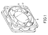
- FIG. 1 is a perspective view of a cooling fan with a light-emitting device in accordance with the present invention
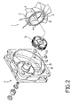
- FIG. 2 is an exploded perspective view of the cooling fan in FIG. 1;
- FIG. 3 is a side plan view in partial section of the cooling fan in FIG. 1;
- FIG. 4 is a partial side plan view in partial section of the cooling fan in FIG. 1;
- FIG. 5 is a circuit diagram of a first embodiment of a drive circuit for the cooling fan with a light-emitting device in FIG. 1;
- FIG. 6 is a circuit diagram of a second embodiment of a drive circuit for the cooling fan with a light-emitting device in FIG. 1.
- a cooling fan with a light-emitting device in accordance with the present invention comprises a frame ( 7 ), multiple light emitting diodes (LIED) ( 13 ), a circuit board ( 10 ), a stator ( 6 ), an impeller ( 1 ) and multiple permanent magnets ( 5 ).
- the frame ( 7 ) with a center comprises a housing ( 8 ) and a stud ( 9 ).
- the housing ( 8 ) has multiple LED holes ( 12 ) formed in and pass through the housing ( 8 ).
- the stud ( 9 ) is perpendicularly extrudes from the center of the frame ( 8 ).
- the impeller ( 1 ) with a center comprises a round casing ( 2 ), a shaft ( 3 ) and multiple blades ( 4 ).
- the casing ( 2 ) has an inside-perimeter.
- the multiple permanent magnets ( 5 ) formed around the inside-perimeter of the casing ( 2 ) are arc-shaped and each has multiple poles (not shown).
- the shall ( 3 ) is formed in the center of the impeller ( 1 ).
- the circuit board ( 10 ) is round in shape with a center portion punched out to go through the stud ( 9 ).
- the stator ( 6 ) has multiple coils, which are securely wound around the stud ( 9 ) and is electrically connected to the circuit board ( 10 ).
- the impeller ( 1 ) sits inside the housing ( 8 ) of the frame ( 7 ) with the stator ( 6 ) completely surround by the permanent magnets ( 5 ) inside the casing ( 2 ).
- the impeller ( 1 ) is rotated by the interaction force between the magnetic forces generated by the stator ( 6 ) and the permanent magnets ( 5 ).
- Each light emitting diode (LEDs) ( 13 ) is mounted inside one of the LED holes ( 12 ) on the housing ( 8 ) pointing inwards to the impeller ( 1 ).
- the rotational of the impeller ( 1 ) is controlled by a drive circuit (not shown) on the circuit board ( 10 ), and the multiple LEDs ( 13 ) are powered by the same circuit board ( 10 ) or an outside circuit board (tot shown).
- Each LED ( 13 ) projects light towards the impeller ( 1 ) and to the frame ( 7 ) so the light will reflects and bounces all over the fan.
- the frame ( 7 ) and the impeller ( 1 ) are transparent or translucent, the light will produce a fantastic visual effect so the whole fan will glow in the dark.
- the LEDs ( 13 ) are connected to the same power source connected to the drive circuit that controls the impeller ( 1 ).
- the drive circuit comprises a driving IC ( 22 ), a power source (not numbered), stator coils (L 1 , L 2 ) and isolation capacitors (C 1 , C 2 ).
- the driving IC ( 22 ) has a power input terminal (not numbered), a ground terminal (not numbered) and two input terminals (not numbered).
- the power input terminal is connected a power unit (not numbered), and the input terminals are connected respectively to the stator coils (L 1 , L 2 ).
- the power source provides the power to the driving IC ( 22 ), and the driving IC ( 22 ) will control the two input terminals to selectively allow electricity to flow through the stator coils (L 1 , L 2 ) and switch the electromagnetic poles in the stator ( 6 ).
- the isolation capacitor (C 1 , C 2 ) will provide discharge, charge and wave filter function.
- the power unit is also connected to the multiple LEDs ( 13 ) so when the power rotates the fan ( 1 ) and the LED ( 13 ) illuminate.
- the LEDs ( 13 ) can he made to twinkle or blink corresponding to the rotational speed of the impeller ( 1 ) by adding a twinkle control circuit ( 23 ) to the drive circuit.
- the rotation of the impeller ( 1 ) is controlled by the driving IC ( 22 ) by switching the flow of electricity to each coil (L 1 , L 2 ), and the driving IC ( 22 ) is connected to a twinkled control circuit ( 23 ).
- the twinkled control circuit ( 23 ) consists of a transistor (TR), a counter (U 2 ) and a decoder (U 1 ).
- the transistor (TR) has base, collector and emitter.
- the base of the transistor (TR) is connected to the driving IC ( 22 ), the collector of the transistor ( 7 TR) is connected to the counter (U 2 ) and the emitter of the transistor (TR) is connected to ground.
- the counter (U 2 ) is connected to the decoder (U I) and multiple output terminals of the decoder (U I), which are connected respectively to an anode of the LEDs (I 3 ).
- the counter (U 2 ) produce, a pulse signal to the decoder (U 1 ), and then the decoder (U 1 ) decodes the signals from the counter (U 2 ) and causes the LEDs ( 13 ) to twinkle.
- the twinkle control circuit ( 23 ) responds based on the rotational speed of the impeller ( 1 ) to determine the frequency at which the LEDs ( 13 ) twinkled.
- the design will give the cooling fan a distinctive vision effect and more variation.
- the drive circuit can be designed to provide a warning signal if the cooling fan breaks down.
- the LEDs ( 13 ) can also be controlled by an outside drive circuit.
Abstract
Description
- 1. Field of the Invention
- The present invention relates to a cooling fan, and more particularly to a cooling fan with light-emitting device.
- 2. Description of Related Art
- In a computer system, as the CPU speed increases, it dissipates more and more heat to the system. Nowadays the temperature inside a computer gets so high that a cooling fan or multi-cooling fans displacement is needed to protect the system from overheat.
- The purpose of a cooling fan is to suck or exhaust the air in or out a computer system thus to cool the components inside the system. The ability to move more air through the fan is the major factor that a fan designer will focus on. A conventional cooling fan is black in color and the appearance of the fan is almost identical to one another in the market in terms of size and structure. When a user searches for a cooling fan for his or her computer, the cooling capacity of the cooling fan will likely be the major factor to consider for.
- Nowadays a personal computer (PC) has evolved from a gray ugly box twenty years ago to a multi media consumer electronic product in variety of shapes. It can he designed as a home entertaining center sitting side by side with the audio equipment in the sitting room or it can he a gaming machine with tremendous processing power in the family room. In either case, the appearance of a PC will play a significant role in attracting buyer attention. A cooling fan in a PC may be visible and it can be a vital part to the appearance of a PC. In this case a conventional black cooling fan may not serve the purpose well. A cooling fan not only cool the system but also provide attractive look will definitely attract more users to use it. To add visual attractiveness to a cooling fan is one way to attract more users.
- The main objective of the present invention is to provide a means of increasing visual attractiveness of a cooling fan by adding a light-emitting device to it.
- A cooling fan with a light-emitting device has a frame, multiple light-emitting diodes (LEDs), a circuit board, a stator, permanent magnets and an impeller. The permanent magnets are formed around a inside-perimeter of the casing of the impeller. The impeller is rotated by the interaction force between poles of the electromagnetized stator and poles of the permanent magnets in the impeller. The rotational speed of the impeller is controlled by drive circuitry on the circuit board. Each LED projects light towards the impeller and to the frame so the light will reflects and bounces all over the fan to produce a fantastic visual effect. The LEDs can be made to twinkle based on the rotational speed of the fan to increase the visual attractiveness.
- Further benefits and advantages of the present invention will become apparent after a careful reading of the detailed description with appropriate reference to the accompanying drawings.
- FIG. 1 is a perspective view of a cooling fan with a light-emitting device in accordance with the present invention;
- FIG. 2 is an exploded perspective view of the cooling fan in FIG. 1;
- FIG. 3 is a side plan view in partial section of the cooling fan in FIG. 1;
- FIG. 4 is a partial side plan view in partial section of the cooling fan in FIG. 1;
- FIG. 5 is a circuit diagram of a first embodiment of a drive circuit for the cooling fan with a light-emitting device in FIG. 1; and
- FIG. 6 is a circuit diagram of a second embodiment of a drive circuit for the cooling fan with a light-emitting device in FIG. 1.
- With reference to FIGS. 1 to 4, a cooling fan with a light-emitting device in accordance with the present invention comprises a frame (7), multiple light emitting diodes (LIED) (13), a circuit board (10), a stator (6), an impeller (1) and multiple permanent magnets (5). The frame (7) with a center comprises a housing (8) and a stud (9). The housing (8) has multiple LED holes (12) formed in and pass through the housing (8). The stud (9) is perpendicularly extrudes from the center of the frame (8). The impeller (1) with a center comprises a round casing (2), a shaft (3) and multiple blades (4). The casing (2) has an inside-perimeter. The multiple permanent magnets (5) formed around the inside-perimeter of the casing (2) are arc-shaped and each has multiple poles (not shown). The shall (3) is formed in the center of the impeller (1). The circuit board (10) is round in shape with a center portion punched out to go through the stud (9). The stator (6) has multiple coils, which are securely wound around the stud (9) and is electrically connected to the circuit board (10). With the shaft (3) go through the stator (6) and into the stud (9), the impeller (1) sits inside the housing (8) of the frame (7) with the stator (6) completely surround by the permanent magnets (5) inside the casing (2). The impeller (1) is rotated by the interaction force between the magnetic forces generated by the stator (6) and the permanent magnets (5).
- Each light emitting diode (LEDs) ( 13) is mounted inside one of the LED holes (12) on the housing (8) pointing inwards to the impeller (1). The rotational of the impeller (1) is controlled by a drive circuit (not shown) on the circuit board (10), and the multiple LEDs (13) are powered by the same circuit board (10) or an outside circuit board (tot shown). Each LED (13) projects light towards the impeller (1) and to the frame (7) so the light will reflects and bounces all over the fan. When the frame (7) and the impeller (1) are transparent or translucent, the light will produce a fantastic visual effect so the whole fan will glow in the dark.
- Please refer to FIG. 5. The LEDs ( 13) are connected to the same power source connected to the drive circuit that controls the impeller (1). The drive circuit comprises a driving IC (22), a power source (not numbered), stator coils (L1, L2) and isolation capacitors (C1, C2). The driving IC (22) has a power input terminal (not numbered), a ground terminal (not numbered) and two input terminals (not numbered). The power input terminal is connected a power unit (not numbered), and the input terminals are connected respectively to the stator coils (L1, L2). The power source provides the power to the driving IC (22), and the driving IC (22) will control the two input terminals to selectively allow electricity to flow through the stator coils (L1, L2) and switch the electromagnetic poles in the stator (6). The isolation capacitor (C1, C2) will provide discharge, charge and wave filter function. The power unit is also connected to the multiple LEDs (13) so when the power rotates the fan (1) and the LED (13) illuminate.
- With reference to FIG. 6, the LEDs ( 13) can he made to twinkle or blink corresponding to the rotational speed of the impeller (1) by adding a twinkle control circuit (23) to the drive circuit. The rotation of the impeller (1) is controlled by the driving IC (22) by switching the flow of electricity to each coil (L1, L2), and the driving IC (22) is connected to a twinkled control circuit (23). The twinkled control circuit (23) consists of a transistor (TR), a counter (U2) and a decoder (U1). The transistor (TR) has base, collector and emitter. The base of the transistor (TR) is connected to the driving IC (22), the collector of the transistor (7TR) is connected to the counter (U2) and the emitter of the transistor (TR) is connected to ground. The counter (U2) is connected to the decoder (U I) and multiple output terminals of the decoder (U I), which are connected respectively to an anode of the LEDs (I 3). When the driving IC (22) is operating and outputting to the transistor (TR), the transistor (TR) will receive the signal of the rotational speed of the impeller (1) and make a pulse signal to the counter 18 (U2). The counter (U2) produce, a pulse signal to the decoder (U1), and then the decoder (U1) decodes the signals from the counter (U2) and causes the LEDs (13) to twinkle. The twinkle control circuit (23) responds based on the rotational speed of the impeller (1) to determine the frequency at which the LEDs (13) twinkled. The design will give the cooling fan a distinctive vision effect and more variation. Furthermore, the drive circuit can be designed to provide a warning signal if the cooling fan breaks down.
- Besides the embedded drive circuit described above, the LEDs ( 13) can also be controlled by an outside drive circuit.
- Although the invention has been explained ill relation to its preferred embodiment, many other possible modifications and variations can be made without departing from the spirit and scope of the invention as hereinafter claimed.
Claims (8)
Applications Claiming Priority (3)
| Application Number | Priority Date | Filing Date | Title |
|---|---|---|---|
| TW91204386U | 2002-04-04 | ||
| TW091204386 | 2002-04-04 | ||
| TW091204386U TW539169U (en) | 2002-04-04 | 2002-04-04 | Air blower with lighting effect |
Publications (2)
| Publication Number | Publication Date |
|---|---|
| US20030190884A1 true US20030190884A1 (en) | 2003-10-09 |
| US6679771B2 US6679771B2 (en) | 2004-01-20 |
Family
ID=28673340
Family Applications (1)
| Application Number | Title | Priority Date | Filing Date |
|---|---|---|---|
| US10/403,048 Expired - Fee Related US6679771B2 (en) | 2002-04-04 | 2003-04-01 | Cooling fan with light-emitting device |
Country Status (2)
| Country | Link |
|---|---|
| US (1) | US6679771B2 (en) |
| TW (1) | TW539169U (en) |
Cited By (6)
| Publication number | Priority date | Publication date | Assignee | Title |
|---|---|---|---|---|
| CN100436830C (en) * | 2005-09-21 | 2008-11-26 | 鸿富锦精密工业(深圳)有限公司 | Fan |
| CN1952838B (en) * | 2005-10-21 | 2012-03-14 | 鸿富锦精密工业(深圳)有限公司 | Overheat indicating circuit for mainboard |
| US9058955B2 (en) | 2012-12-06 | 2015-06-16 | GE Lighting Solutions, LLC | Lamp comprising active cooling device for thermal management |
| US20170314777A1 (en) * | 2016-04-29 | 2017-11-02 | In Win Development, Inc. | MultiLED Fan Controller Aparatus |
| US20190331122A1 (en) * | 2018-04-30 | 2019-10-31 | Cooler Master Technology Inc. | Illumination fan |
| US20220057080A1 (en) * | 2020-08-21 | 2022-02-24 | Vast Glory Electronics & Hardware & Plastic(Hui Zhou) Ltd. | Light emitting fan and heat dissipation device |
Families Citing this family (8)
| Publication number | Priority date | Publication date | Assignee | Title |
|---|---|---|---|---|
| TWM288394U (en) * | 2005-09-08 | 2006-03-01 | Power Cooler Entpr Co Ltd | Fan |
| US20070237636A1 (en) * | 2006-04-07 | 2007-10-11 | Sam Hsu | Computer cooling fan with display device |
| TWM333479U (en) * | 2007-11-01 | 2008-06-01 | Asustek Comp Inc | Electrical fan and board card |
| DE102008004141A1 (en) | 2008-01-14 | 2009-07-16 | Hong Fu Jin Precision Industry (Shenzhen) Co., Ltd., Shenzhen | Ventilator for cooling heat producing element, e.g. central processing unit, has frame with housing and plate connected with housing, where centric tube extends from center of plate |
| US10624275B1 (en) * | 2010-03-23 | 2020-04-21 | Myles D. Lewis | Semi-automated crop production system |
| CN103166411B (en) * | 2011-12-12 | 2016-09-07 | 德昌电机(深圳)有限公司 | Brush motor and use the fan of this brush motor |
| US10677252B2 (en) * | 2017-11-22 | 2020-06-09 | Asia Vital Components Co., Ltd. | Fan structure |
| TWI674362B (en) * | 2018-08-03 | 2019-10-11 | 建準電機工業股份有限公司 | Glare cooling fan and its light guide fan wheel |
Citations (8)
| Publication number | Priority date | Publication date | Assignee | Title |
|---|---|---|---|---|
| US5063834A (en) * | 1988-06-10 | 1991-11-12 | Halton Oy | Focussed ventilation procedure and focussed ventilation means |
| US5721670A (en) * | 1995-12-20 | 1998-02-24 | Northern Telecom Limited | Electronic equipment having air flow cooling passages |
| US5722887A (en) * | 1995-08-17 | 1998-03-03 | Tamarack Technologies, Inc. | Automatic program ventilation control system |
| US5881806A (en) * | 1997-08-18 | 1999-03-16 | University Of Central Florida | Air distribution fan and outside air damper recycling control |
| US5969941A (en) * | 1997-02-12 | 1999-10-19 | Samsung Electronics Co., Ltd. | Device for mounting fan in a portable computer |
| US6042474A (en) * | 1997-06-04 | 2000-03-28 | Lsi Logic Corporation | Compact ventilation unit with exhaust ports for electronic apparatus |
| US6285548B1 (en) * | 2000-08-18 | 2001-09-04 | Quantum Bridge Communications, Inc. | Face plate for a chassis for high frequency components |
| US6315031B1 (en) * | 1995-03-31 | 2001-11-13 | Matsushita Electric Industrial Co., Ltd. | Heat sink apparatus, blower for use therein and electronic equipment using the same apparatus |
-
2002
- 2002-04-04 TW TW091204386U patent/TW539169U/en not_active IP Right Cessation
-
2003
- 2003-04-01 US US10/403,048 patent/US6679771B2/en not_active Expired - Fee Related
Patent Citations (8)
| Publication number | Priority date | Publication date | Assignee | Title |
|---|---|---|---|---|
| US5063834A (en) * | 1988-06-10 | 1991-11-12 | Halton Oy | Focussed ventilation procedure and focussed ventilation means |
| US6315031B1 (en) * | 1995-03-31 | 2001-11-13 | Matsushita Electric Industrial Co., Ltd. | Heat sink apparatus, blower for use therein and electronic equipment using the same apparatus |
| US5722887A (en) * | 1995-08-17 | 1998-03-03 | Tamarack Technologies, Inc. | Automatic program ventilation control system |
| US5721670A (en) * | 1995-12-20 | 1998-02-24 | Northern Telecom Limited | Electronic equipment having air flow cooling passages |
| US5969941A (en) * | 1997-02-12 | 1999-10-19 | Samsung Electronics Co., Ltd. | Device for mounting fan in a portable computer |
| US6042474A (en) * | 1997-06-04 | 2000-03-28 | Lsi Logic Corporation | Compact ventilation unit with exhaust ports for electronic apparatus |
| US5881806A (en) * | 1997-08-18 | 1999-03-16 | University Of Central Florida | Air distribution fan and outside air damper recycling control |
| US6285548B1 (en) * | 2000-08-18 | 2001-09-04 | Quantum Bridge Communications, Inc. | Face plate for a chassis for high frequency components |
Cited By (8)
| Publication number | Priority date | Publication date | Assignee | Title |
|---|---|---|---|---|
| CN100436830C (en) * | 2005-09-21 | 2008-11-26 | 鸿富锦精密工业(深圳)有限公司 | Fan |
| CN1952838B (en) * | 2005-10-21 | 2012-03-14 | 鸿富锦精密工业(深圳)有限公司 | Overheat indicating circuit for mainboard |
| US9058955B2 (en) | 2012-12-06 | 2015-06-16 | GE Lighting Solutions, LLC | Lamp comprising active cooling device for thermal management |
| US20170314777A1 (en) * | 2016-04-29 | 2017-11-02 | In Win Development, Inc. | MultiLED Fan Controller Aparatus |
| US20190331122A1 (en) * | 2018-04-30 | 2019-10-31 | Cooler Master Technology Inc. | Illumination fan |
| US10830243B2 (en) * | 2018-04-30 | 2020-11-10 | Cooler Master Technology Inc. | Illumination fan |
| US20220057080A1 (en) * | 2020-08-21 | 2022-02-24 | Vast Glory Electronics & Hardware & Plastic(Hui Zhou) Ltd. | Light emitting fan and heat dissipation device |
| US11486571B2 (en) * | 2020-08-21 | 2022-11-01 | Vast Glory Electronics & Hardware & Plastic(Hui Zhou) Ltd. | Light emitting fan and heat dissipation device |
Also Published As
| Publication number | Publication date |
|---|---|
| TW539169U (en) | 2003-06-21 |
| US6679771B2 (en) | 2004-01-20 |
Similar Documents
| Publication | Publication Date | Title |
|---|---|---|
| US6679771B2 (en) | Cooling fan with light-emitting device | |
| US7563070B2 (en) | Cooling fan | |
| US20070237636A1 (en) | Computer cooling fan with display device | |
| US7183939B1 (en) | Shining fan structure for displaying images | |
| US8040674B2 (en) | Heat dissipation module and fan thereof | |
| US20060012973A1 (en) | Cooling fan with a light-emitting device | |
| US6817830B1 (en) | Ceiling fan with multiple rotors | |
| US20100284149A1 (en) | Power supply and a housing structure with the power supply | |
| US6572245B2 (en) | Nightlight with dynamic image effect | |
| US20050213302A1 (en) | Heat-dissipating device for a portable computer | |
| US20060133920A1 (en) | Cooling fan with luminous device | |
| WO2022140035A1 (en) | Folding hand fan with illuminated ribs | |
| US7121697B2 (en) | Illumination device for computer fan | |
| US6857760B2 (en) | Power outlet with night-vision-function | |
| US20060028823A1 (en) | Cooling device with light control structure | |
| US20060152683A1 (en) | Cooling fan with embedded light source | |
| US20110043113A1 (en) | Faucet assembly | |
| US20070126293A1 (en) | Decorative lighting device | |
| US20050031464A1 (en) | Heat-dissipating fan device with light-emitting capability | |
| US20050116477A1 (en) | Automatic power generation light-image fan device | |
| US6461219B1 (en) | Animated display | |
| JP2004221078A (en) | Push-button switch with led indicator | |
| TWM563734U (en) | Fan structure with power generating coil | |
| CN216477935U (en) | Ultrathin fan | |
| CN219795620U (en) | Intelligent cooling fan |
Legal Events
| Date | Code | Title | Description |
|---|---|---|---|
| AS | Assignment |
Owner name: ANTEC, INC., CALIFORNIA Free format text: ASSIGNMENT OF ASSIGNORS INTEREST;ASSIGNOR:LEE, ANDREW;REEL/FRAME:013927/0272 Effective date: 20030328 |
|
| RR | Request for reexamination filed |
Effective date: 20060213 |
|
| FPAY | Fee payment |
Year of fee payment: 4 |
|
| B1 | Reexamination certificate first reexamination |
Free format text: THE PATENTABILITY OF CLAIMS 3 AND 4 IS CONFIRMED. CLAIMS 1, 2 AND 5-8 ARE CANCELLED. |
|
| FPAY | Fee payment |
Year of fee payment: 8 |
|
| AS | Assignment |
Owner name: ANTEC INC., CALIFORNIA Free format text: ASSIGNMENT OF ASSIGNORS INTEREST;ASSIGNOR:ANTEC INC.;REEL/FRAME:033388/0109 Effective date: 20140707 |
|
| REMI | Maintenance fee reminder mailed | ||
| LAPS | Lapse for failure to pay maintenance fees | ||
| STCH | Information on status: patent discontinuation |
Free format text: PATENT EXPIRED DUE TO NONPAYMENT OF MAINTENANCE FEES UNDER 37 CFR 1.362 |
|
| FP | Lapsed due to failure to pay maintenance fee |
Effective date: 20160120 |