US20030190744A1 - Method and apparatus for performing biological reactions on a substrate surface - Google Patents
Method and apparatus for performing biological reactions on a substrate surface Download PDFInfo
- Publication number
- US20030190744A1 US20030190744A1 US10/394,484 US39448403A US2003190744A1 US 20030190744 A1 US20030190744 A1 US 20030190744A1 US 39448403 A US39448403 A US 39448403A US 2003190744 A1 US2003190744 A1 US 2003190744A1
- Authority
- US
- United States
- Prior art keywords
- flexible
- permeable layer
- gas permeable
- substrate
- layer
- Prior art date
- Legal status (The legal status is an assumption and is not a legal conclusion. Google has not performed a legal analysis and makes no representation as to the accuracy of the status listed.)
- Abandoned
Links
- 238000006243 chemical reaction Methods 0.000 title claims abstract description 91
- 239000000758 substrate Substances 0.000 title claims abstract description 80
- 238000000034 method Methods 0.000 title claims abstract description 19
- 239000012530 fluid Substances 0.000 claims abstract description 50
- 238000009792 diffusion process Methods 0.000 claims abstract description 14
- 230000001070 adhesive effect Effects 0.000 claims description 47
- 239000000853 adhesive Substances 0.000 claims description 44
- 150000001875 compounds Chemical class 0.000 claims description 11
- 239000012528 membrane Substances 0.000 claims description 9
- 239000007787 solid Substances 0.000 claims description 9
- 239000003638 chemical reducing agent Substances 0.000 claims description 8
- 239000007788 liquid Substances 0.000 claims description 7
- -1 (c) a flexible Substances 0.000 claims description 5
- 229920006362 Teflon® Polymers 0.000 claims description 4
- 239000004809 Teflon Substances 0.000 claims description 2
- 239000000523 sample Substances 0.000 abstract description 54
- 238000000018 DNA microarray Methods 0.000 abstract description 25
- 238000003491 array Methods 0.000 abstract description 18
- 108091034117 Oligonucleotide Proteins 0.000 abstract description 11
- 230000027455 binding Effects 0.000 abstract description 6
- 238000002156 mixing Methods 0.000 abstract description 4
- 239000007789 gas Substances 0.000 description 80
- 239000000499 gel Substances 0.000 description 20
- UAOUIVVJBYDFKD-XKCDOFEDSA-N (1R,9R,10S,11R,12R,15S,18S,21R)-10,11,21-trihydroxy-8,8-dimethyl-14-methylidene-4-(prop-2-enylamino)-20-oxa-5-thia-3-azahexacyclo[9.7.2.112,15.01,9.02,6.012,18]henicosa-2(6),3-dien-13-one Chemical compound C([C@@H]1[C@@H](O)[C@@]23C(C1=C)=O)C[C@H]2[C@]12C(N=C(NCC=C)S4)=C4CC(C)(C)[C@H]1[C@H](O)[C@]3(O)OC2 UAOUIVVJBYDFKD-XKCDOFEDSA-N 0.000 description 15
- 229920002401 polyacrylamide Polymers 0.000 description 11
- 239000000017 hydrogel Substances 0.000 description 10
- 239000000243 solution Substances 0.000 description 10
- HRPVXLWXLXDGHG-UHFFFAOYSA-N Acrylamide Chemical compound NC(=O)C=C HRPVXLWXLXDGHG-UHFFFAOYSA-N 0.000 description 8
- JLCPHMBAVCMARE-UHFFFAOYSA-N [3-[[3-[[3-[[3-[[3-[[3-[[3-[[3-[[3-[[3-[[3-[[5-(2-amino-6-oxo-1H-purin-9-yl)-3-[[3-[[3-[[3-[[3-[[3-[[5-(2-amino-6-oxo-1H-purin-9-yl)-3-[[5-(2-amino-6-oxo-1H-purin-9-yl)-3-hydroxyoxolan-2-yl]methoxy-hydroxyphosphoryl]oxyoxolan-2-yl]methoxy-hydroxyphosphoryl]oxy-5-(5-methyl-2,4-dioxopyrimidin-1-yl)oxolan-2-yl]methoxy-hydroxyphosphoryl]oxy-5-(6-aminopurin-9-yl)oxolan-2-yl]methoxy-hydroxyphosphoryl]oxy-5-(6-aminopurin-9-yl)oxolan-2-yl]methoxy-hydroxyphosphoryl]oxy-5-(6-aminopurin-9-yl)oxolan-2-yl]methoxy-hydroxyphosphoryl]oxy-5-(6-aminopurin-9-yl)oxolan-2-yl]methoxy-hydroxyphosphoryl]oxyoxolan-2-yl]methoxy-hydroxyphosphoryl]oxy-5-(5-methyl-2,4-dioxopyrimidin-1-yl)oxolan-2-yl]methoxy-hydroxyphosphoryl]oxy-5-(4-amino-2-oxopyrimidin-1-yl)oxolan-2-yl]methoxy-hydroxyphosphoryl]oxy-5-(5-methyl-2,4-dioxopyrimidin-1-yl)oxolan-2-yl]methoxy-hydroxyphosphoryl]oxy-5-(5-methyl-2,4-dioxopyrimidin-1-yl)oxolan-2-yl]methoxy-hydroxyphosphoryl]oxy-5-(6-aminopurin-9-yl)oxolan-2-yl]methoxy-hydroxyphosphoryl]oxy-5-(6-aminopurin-9-yl)oxolan-2-yl]methoxy-hydroxyphosphoryl]oxy-5-(4-amino-2-oxopyrimidin-1-yl)oxolan-2-yl]methoxy-hydroxyphosphoryl]oxy-5-(4-amino-2-oxopyrimidin-1-yl)oxolan-2-yl]methoxy-hydroxyphosphoryl]oxy-5-(4-amino-2-oxopyrimidin-1-yl)oxolan-2-yl]methoxy-hydroxyphosphoryl]oxy-5-(6-aminopurin-9-yl)oxolan-2-yl]methoxy-hydroxyphosphoryl]oxy-5-(4-amino-2-oxopyrimidin-1-yl)oxolan-2-yl]methyl [5-(6-aminopurin-9-yl)-2-(hydroxymethyl)oxolan-3-yl] hydrogen phosphate Polymers Cc1cn(C2CC(OP(O)(=O)OCC3OC(CC3OP(O)(=O)OCC3OC(CC3O)n3cnc4c3nc(N)[nH]c4=O)n3cnc4c3nc(N)[nH]c4=O)C(COP(O)(=O)OC3CC(OC3COP(O)(=O)OC3CC(OC3COP(O)(=O)OC3CC(OC3COP(O)(=O)OC3CC(OC3COP(O)(=O)OC3CC(OC3COP(O)(=O)OC3CC(OC3COP(O)(=O)OC3CC(OC3COP(O)(=O)OC3CC(OC3COP(O)(=O)OC3CC(OC3COP(O)(=O)OC3CC(OC3COP(O)(=O)OC3CC(OC3COP(O)(=O)OC3CC(OC3COP(O)(=O)OC3CC(OC3COP(O)(=O)OC3CC(OC3COP(O)(=O)OC3CC(OC3COP(O)(=O)OC3CC(OC3COP(O)(=O)OC3CC(OC3CO)n3cnc4c(N)ncnc34)n3ccc(N)nc3=O)n3cnc4c(N)ncnc34)n3ccc(N)nc3=O)n3ccc(N)nc3=O)n3ccc(N)nc3=O)n3cnc4c(N)ncnc34)n3cnc4c(N)ncnc34)n3cc(C)c(=O)[nH]c3=O)n3cc(C)c(=O)[nH]c3=O)n3ccc(N)nc3=O)n3cc(C)c(=O)[nH]c3=O)n3cnc4c3nc(N)[nH]c4=O)n3cnc4c(N)ncnc34)n3cnc4c(N)ncnc34)n3cnc4c(N)ncnc34)n3cnc4c(N)ncnc34)O2)c(=O)[nH]c1=O JLCPHMBAVCMARE-UHFFFAOYSA-N 0.000 description 8
- 239000011521 glass Substances 0.000 description 8
- 238000006116 polymerization reaction Methods 0.000 description 8
- 238000003556 assay Methods 0.000 description 7
- 239000000463 material Substances 0.000 description 7
- 229920003023 plastic Polymers 0.000 description 7
- 239000004033 plastic Substances 0.000 description 7
- 239000000126 substance Substances 0.000 description 7
- 239000012472 biological sample Substances 0.000 description 6
- 229920000642 polymer Polymers 0.000 description 6
- 239000011148 porous material Substances 0.000 description 6
- 238000004873 anchoring Methods 0.000 description 5
- 230000000295 complement effect Effects 0.000 description 5
- 238000005516 engineering process Methods 0.000 description 5
- 239000003446 ligand Substances 0.000 description 5
- 238000002493 microarray Methods 0.000 description 5
- 230000002411 adverse Effects 0.000 description 4
- 239000000427 antigen Substances 0.000 description 4
- 108091007433 antigens Proteins 0.000 description 4
- 102000036639 antigens Human genes 0.000 description 4
- 238000009396 hybridization Methods 0.000 description 4
- 239000000178 monomer Substances 0.000 description 4
- 150000007523 nucleic acids Chemical class 0.000 description 4
- 238000011160 research Methods 0.000 description 4
- XLYOFNOQVPJJNP-UHFFFAOYSA-N water Substances O XLYOFNOQVPJJNP-UHFFFAOYSA-N 0.000 description 4
- 239000004971 Cross linker Substances 0.000 description 3
- PEDCQBHIVMGVHV-UHFFFAOYSA-N Glycerine Chemical compound OCC(O)CO PEDCQBHIVMGVHV-UHFFFAOYSA-N 0.000 description 3
- 238000004519 manufacturing process Methods 0.000 description 3
- 238000002844 melting Methods 0.000 description 3
- 230000008018 melting Effects 0.000 description 3
- 108020004707 nucleic acids Proteins 0.000 description 3
- 102000039446 nucleic acids Human genes 0.000 description 3
- 238000002966 oligonucleotide array Methods 0.000 description 3
- 108090000765 processed proteins & peptides Proteins 0.000 description 3
- 102000004196 processed proteins & peptides Human genes 0.000 description 3
- 108020003175 receptors Proteins 0.000 description 3
- 229920006370 Kynar Polymers 0.000 description 2
- KWYHDKDOAIKMQN-UHFFFAOYSA-N N,N,N',N'-tetramethylethylenediamine Chemical compound CN(C)CCN(C)C KWYHDKDOAIKMQN-UHFFFAOYSA-N 0.000 description 2
- 108020005187 Oligonucleotide Probes Proteins 0.000 description 2
- 239000002202 Polyethylene glycol Substances 0.000 description 2
- 239000002390 adhesive tape Substances 0.000 description 2
- 150000001408 amides Chemical class 0.000 description 2
- ROOXNKNUYICQNP-UHFFFAOYSA-N ammonium persulfate Chemical compound [NH4+].[NH4+].[O-]S(=O)(=O)OOS([O-])(=O)=O ROOXNKNUYICQNP-UHFFFAOYSA-N 0.000 description 2
- 238000013459 approach Methods 0.000 description 2
- 230000015572 biosynthetic process Effects 0.000 description 2
- 239000000919 ceramic Substances 0.000 description 2
- 238000010382 chemical cross-linking Methods 0.000 description 2
- 125000003636 chemical group Chemical group 0.000 description 2
- 238000007385 chemical modification Methods 0.000 description 2
- 238000004132 cross linking Methods 0.000 description 2
- 230000001351 cycling effect Effects 0.000 description 2
- 229920001971 elastomer Polymers 0.000 description 2
- 150000002148 esters Chemical class 0.000 description 2
- 230000008020 evaporation Effects 0.000 description 2
- 238000001704 evaporation Methods 0.000 description 2
- 239000011888 foil Substances 0.000 description 2
- 239000011261 inert gas Substances 0.000 description 2
- 239000003999 initiator Substances 0.000 description 2
- 238000002347 injection Methods 0.000 description 2
- 239000007924 injection Substances 0.000 description 2
- 230000003993 interaction Effects 0.000 description 2
- 239000000203 mixture Substances 0.000 description 2
- 238000012986 modification Methods 0.000 description 2
- 230000004048 modification Effects 0.000 description 2
- ZIUHHBKFKCYYJD-UHFFFAOYSA-N n,n'-methylenebisacrylamide Chemical compound C=CC(=O)NCNC(=O)C=C ZIUHHBKFKCYYJD-UHFFFAOYSA-N 0.000 description 2
- 239000002751 oligonucleotide probe Substances 0.000 description 2
- 229920001223 polyethylene glycol Polymers 0.000 description 2
- 229940057847 polyethylene glycol 600 Drugs 0.000 description 2
- 229920002635 polyurethane Polymers 0.000 description 2
- 239000004814 polyurethane Substances 0.000 description 2
- 108090000623 proteins and genes Proteins 0.000 description 2
- 239000000376 reactant Substances 0.000 description 2
- 239000005060 rubber Substances 0.000 description 2
- 150000003384 small molecules Chemical class 0.000 description 2
- BQCIDUSAKPWEOX-UHFFFAOYSA-N 1,1-Difluoroethene Chemical compound FC(F)=C BQCIDUSAKPWEOX-UHFFFAOYSA-N 0.000 description 1
- 108020003215 DNA Probes Proteins 0.000 description 1
- 230000004544 DNA amplification Effects 0.000 description 1
- 239000003298 DNA probe Substances 0.000 description 1
- 239000002033 PVDF binder Substances 0.000 description 1
- 239000004698 Polyethylene Substances 0.000 description 1
- 239000004743 Polypropylene Substances 0.000 description 1
- 229920001328 Polyvinylidene chloride Polymers 0.000 description 1
- 238000010521 absorption reaction Methods 0.000 description 1
- NIXOWILDQLNWCW-UHFFFAOYSA-N acrylic acid group Chemical group C(C=C)(=O)O NIXOWILDQLNWCW-UHFFFAOYSA-N 0.000 description 1
- 229920006397 acrylic thermoplastic Polymers 0.000 description 1
- 239000000556 agonist Substances 0.000 description 1
- 229910001870 ammonium persulfate Inorganic materials 0.000 description 1
- 238000004458 analytical method Methods 0.000 description 1
- 239000005557 antagonist Substances 0.000 description 1
- 239000007864 aqueous solution Substances 0.000 description 1
- 238000004166 bioassay Methods 0.000 description 1
- 230000015556 catabolic process Effects 0.000 description 1
- 239000003054 catalyst Substances 0.000 description 1
- 239000003153 chemical reaction reagent Substances 0.000 description 1
- 239000011248 coating agent Substances 0.000 description 1
- 238000000576 coating method Methods 0.000 description 1
- 230000001010 compromised effect Effects 0.000 description 1
- 238000007334 copolymerization reaction Methods 0.000 description 1
- 238000005520 cutting process Methods 0.000 description 1
- 230000002950 deficient Effects 0.000 description 1
- 238000006731 degradation reaction Methods 0.000 description 1
- 238000000151 deposition Methods 0.000 description 1
- 238000011161 development Methods 0.000 description 1
- 201000010099 disease Diseases 0.000 description 1
- 208000037265 diseases, disorders, signs and symptoms Diseases 0.000 description 1
- 230000000694 effects Effects 0.000 description 1
- 125000000816 ethylene group Chemical group [H]C([H])([*:1])C([H])([H])[*:2] 0.000 description 1
- 238000004880 explosion Methods 0.000 description 1
- 239000007850 fluorescent dye Substances 0.000 description 1
- 230000002068 genetic effect Effects 0.000 description 1
- 150000004676 glycans Chemical class 0.000 description 1
- 238000010438 heat treatment Methods 0.000 description 1
- 239000005556 hormone Substances 0.000 description 1
- 229940088597 hormone Drugs 0.000 description 1
- 108091008039 hormone receptors Proteins 0.000 description 1
- 230000001900 immune effect Effects 0.000 description 1
- 238000010348 incorporation Methods 0.000 description 1
- 230000000977 initiatory effect Effects 0.000 description 1
- 238000007641 inkjet printing Methods 0.000 description 1
- 238000003780 insertion Methods 0.000 description 1
- 230000037431 insertion Effects 0.000 description 1
- 238000003475 lamination Methods 0.000 description 1
- 239000002207 metabolite Substances 0.000 description 1
- 239000002184 metal Substances 0.000 description 1
- 229910052751 metal Inorganic materials 0.000 description 1
- 150000002739 metals Chemical class 0.000 description 1
- 239000002991 molded plastic Substances 0.000 description 1
- 230000009149 molecular binding Effects 0.000 description 1
- 239000002773 nucleotide Substances 0.000 description 1
- 125000003729 nucleotide group Chemical group 0.000 description 1
- 235000015097 nutrients Nutrition 0.000 description 1
- 238000010943 off-gassing Methods 0.000 description 1
- 238000007645 offset printing Methods 0.000 description 1
- 244000052769 pathogen Species 0.000 description 1
- 229920003229 poly(methyl methacrylate) Polymers 0.000 description 1
- 229920000728 polyester Polymers 0.000 description 1
- 229920000573 polyethylene Polymers 0.000 description 1
- 108091033319 polynucleotide Proteins 0.000 description 1
- 102000040430 polynucleotide Human genes 0.000 description 1
- 239000002157 polynucleotide Substances 0.000 description 1
- 229920001155 polypropylene Polymers 0.000 description 1
- 229920001282 polysaccharide Polymers 0.000 description 1
- 239000005017 polysaccharide Substances 0.000 description 1
- 229920001296 polysiloxane Polymers 0.000 description 1
- 239000005033 polyvinylidene chloride Substances 0.000 description 1
- 229920002981 polyvinylidene fluoride Polymers 0.000 description 1
- 238000002360 preparation method Methods 0.000 description 1
- 239000000047 product Substances 0.000 description 1
- 102000004169 proteins and genes Human genes 0.000 description 1
- 239000012264 purified product Substances 0.000 description 1
- 230000005855 radiation Effects 0.000 description 1
- 239000004065 semiconductor Substances 0.000 description 1
- 238000007873 sieving Methods 0.000 description 1
- 229910052710 silicon Inorganic materials 0.000 description 1
- 239000010703 silicon Substances 0.000 description 1
- 229920002379 silicone rubber Polymers 0.000 description 1
- 125000006850 spacer group Chemical group 0.000 description 1
- 241000894007 species Species 0.000 description 1
- ISXSCDLOGDJUNJ-UHFFFAOYSA-N tert-butyl prop-2-enoate Chemical compound CC(C)(C)OC(=O)C=C ISXSCDLOGDJUNJ-UHFFFAOYSA-N 0.000 description 1
- 238000011179 visual inspection Methods 0.000 description 1
- 239000011534 wash buffer Substances 0.000 description 1
Images


Classifications
-
- B—PERFORMING OPERATIONS; TRANSPORTING
- B01—PHYSICAL OR CHEMICAL PROCESSES OR APPARATUS IN GENERAL
- B01L—CHEMICAL OR PHYSICAL LABORATORY APPARATUS FOR GENERAL USE
- B01L3/00—Containers or dishes for laboratory use, e.g. laboratory glassware; Droppers
- B01L3/50—Containers for the purpose of retaining a material to be analysed, e.g. test tubes
- B01L3/508—Containers for the purpose of retaining a material to be analysed, e.g. test tubes rigid containers not provided for above
- B01L3/5085—Containers for the purpose of retaining a material to be analysed, e.g. test tubes rigid containers not provided for above for multiple samples, e.g. microtitration plates
- B01L3/50853—Containers for the purpose of retaining a material to be analysed, e.g. test tubes rigid containers not provided for above for multiple samples, e.g. microtitration plates with covers or lids
-
- B—PERFORMING OPERATIONS; TRANSPORTING
- B01—PHYSICAL OR CHEMICAL PROCESSES OR APPARATUS IN GENERAL
- B01L—CHEMICAL OR PHYSICAL LABORATORY APPARATUS FOR GENERAL USE
- B01L3/00—Containers or dishes for laboratory use, e.g. laboratory glassware; Droppers
- B01L3/50—Containers for the purpose of retaining a material to be analysed, e.g. test tubes
- B01L3/502—Containers for the purpose of retaining a material to be analysed, e.g. test tubes with fluid transport, e.g. in multi-compartment structures
- B01L3/5027—Containers for the purpose of retaining a material to be analysed, e.g. test tubes with fluid transport, e.g. in multi-compartment structures by integrated microfluidic structures, i.e. dimensions of channels and chambers are such that surface tension forces are important, e.g. lab-on-a-chip
- B01L3/502707—Containers for the purpose of retaining a material to be analysed, e.g. test tubes with fluid transport, e.g. in multi-compartment structures by integrated microfluidic structures, i.e. dimensions of channels and chambers are such that surface tension forces are important, e.g. lab-on-a-chip characterised by the manufacture of the container or its components
-
- B—PERFORMING OPERATIONS; TRANSPORTING
- B01—PHYSICAL OR CHEMICAL PROCESSES OR APPARATUS IN GENERAL
- B01L—CHEMICAL OR PHYSICAL LABORATORY APPARATUS FOR GENERAL USE
- B01L3/00—Containers or dishes for laboratory use, e.g. laboratory glassware; Droppers
- B01L3/50—Containers for the purpose of retaining a material to be analysed, e.g. test tubes
- B01L3/502—Containers for the purpose of retaining a material to be analysed, e.g. test tubes with fluid transport, e.g. in multi-compartment structures
- B01L3/5027—Containers for the purpose of retaining a material to be analysed, e.g. test tubes with fluid transport, e.g. in multi-compartment structures by integrated microfluidic structures, i.e. dimensions of channels and chambers are such that surface tension forces are important, e.g. lab-on-a-chip
- B01L3/502715—Containers for the purpose of retaining a material to be analysed, e.g. test tubes with fluid transport, e.g. in multi-compartment structures by integrated microfluidic structures, i.e. dimensions of channels and chambers are such that surface tension forces are important, e.g. lab-on-a-chip characterised by interfacing components, e.g. fluidic, electrical, optical or mechanical interfaces
-
- B—PERFORMING OPERATIONS; TRANSPORTING
- B01—PHYSICAL OR CHEMICAL PROCESSES OR APPARATUS IN GENERAL
- B01L—CHEMICAL OR PHYSICAL LABORATORY APPARATUS FOR GENERAL USE
- B01L3/00—Containers or dishes for laboratory use, e.g. laboratory glassware; Droppers
- B01L3/50—Containers for the purpose of retaining a material to be analysed, e.g. test tubes
- B01L3/502—Containers for the purpose of retaining a material to be analysed, e.g. test tubes with fluid transport, e.g. in multi-compartment structures
- B01L3/5027—Containers for the purpose of retaining a material to be analysed, e.g. test tubes with fluid transport, e.g. in multi-compartment structures by integrated microfluidic structures, i.e. dimensions of channels and chambers are such that surface tension forces are important, e.g. lab-on-a-chip
- B01L3/502723—Containers for the purpose of retaining a material to be analysed, e.g. test tubes with fluid transport, e.g. in multi-compartment structures by integrated microfluidic structures, i.e. dimensions of channels and chambers are such that surface tension forces are important, e.g. lab-on-a-chip characterised by venting arrangements
-
- B—PERFORMING OPERATIONS; TRANSPORTING
- B01—PHYSICAL OR CHEMICAL PROCESSES OR APPARATUS IN GENERAL
- B01L—CHEMICAL OR PHYSICAL LABORATORY APPARATUS FOR GENERAL USE
- B01L3/00—Containers or dishes for laboratory use, e.g. laboratory glassware; Droppers
- B01L3/50—Containers for the purpose of retaining a material to be analysed, e.g. test tubes
- B01L3/502—Containers for the purpose of retaining a material to be analysed, e.g. test tubes with fluid transport, e.g. in multi-compartment structures
- B01L3/5027—Containers for the purpose of retaining a material to be analysed, e.g. test tubes with fluid transport, e.g. in multi-compartment structures by integrated microfluidic structures, i.e. dimensions of channels and chambers are such that surface tension forces are important, e.g. lab-on-a-chip
- B01L3/50273—Containers for the purpose of retaining a material to be analysed, e.g. test tubes with fluid transport, e.g. in multi-compartment structures by integrated microfluidic structures, i.e. dimensions of channels and chambers are such that surface tension forces are important, e.g. lab-on-a-chip characterised by the means or forces applied to move the fluids
-
- B—PERFORMING OPERATIONS; TRANSPORTING
- B01—PHYSICAL OR CHEMICAL PROCESSES OR APPARATUS IN GENERAL
- B01J—CHEMICAL OR PHYSICAL PROCESSES, e.g. CATALYSIS OR COLLOID CHEMISTRY; THEIR RELEVANT APPARATUS
- B01J2219/00—Chemical, physical or physico-chemical processes in general; Their relevant apparatus
- B01J2219/00274—Sequential or parallel reactions; Apparatus and devices for combinatorial chemistry or for making arrays; Chemical library technology
- B01J2219/00583—Features relative to the processes being carried out
- B01J2219/00596—Solid-phase processes
-
- B—PERFORMING OPERATIONS; TRANSPORTING
- B01—PHYSICAL OR CHEMICAL PROCESSES OR APPARATUS IN GENERAL
- B01J—CHEMICAL OR PHYSICAL PROCESSES, e.g. CATALYSIS OR COLLOID CHEMISTRY; THEIR RELEVANT APPARATUS
- B01J2219/00—Chemical, physical or physico-chemical processes in general; Their relevant apparatus
- B01J2219/00274—Sequential or parallel reactions; Apparatus and devices for combinatorial chemistry or for making arrays; Chemical library technology
- B01J2219/00583—Features relative to the processes being carried out
- B01J2219/00603—Making arrays on substantially continuous surfaces
- B01J2219/00659—Two-dimensional arrays
-
- B—PERFORMING OPERATIONS; TRANSPORTING
- B01—PHYSICAL OR CHEMICAL PROCESSES OR APPARATUS IN GENERAL
- B01J—CHEMICAL OR PHYSICAL PROCESSES, e.g. CATALYSIS OR COLLOID CHEMISTRY; THEIR RELEVANT APPARATUS
- B01J2219/00—Chemical, physical or physico-chemical processes in general; Their relevant apparatus
- B01J2219/00274—Sequential or parallel reactions; Apparatus and devices for combinatorial chemistry or for making arrays; Chemical library technology
- B01J2219/0068—Means for controlling the apparatus of the process
- B01J2219/00702—Processes involving means for analysing and characterising the products
-
- B—PERFORMING OPERATIONS; TRANSPORTING
- B01—PHYSICAL OR CHEMICAL PROCESSES OR APPARATUS IN GENERAL
- B01J—CHEMICAL OR PHYSICAL PROCESSES, e.g. CATALYSIS OR COLLOID CHEMISTRY; THEIR RELEVANT APPARATUS
- B01J2219/00—Chemical, physical or physico-chemical processes in general; Their relevant apparatus
- B01J2219/00274—Sequential or parallel reactions; Apparatus and devices for combinatorial chemistry or for making arrays; Chemical library technology
- B01J2219/00718—Type of compounds synthesised
- B01J2219/0072—Organic compounds
- B01J2219/00722—Nucleotides
-
- B—PERFORMING OPERATIONS; TRANSPORTING
- B01—PHYSICAL OR CHEMICAL PROCESSES OR APPARATUS IN GENERAL
- B01L—CHEMICAL OR PHYSICAL LABORATORY APPARATUS FOR GENERAL USE
- B01L2200/00—Solutions for specific problems relating to chemical or physical laboratory apparatus
- B01L2200/02—Adapting objects or devices to another
- B01L2200/026—Fluid interfacing between devices or objects, e.g. connectors, inlet details
- B01L2200/027—Fluid interfacing between devices or objects, e.g. connectors, inlet details for microfluidic devices
-
- B—PERFORMING OPERATIONS; TRANSPORTING
- B01—PHYSICAL OR CHEMICAL PROCESSES OR APPARATUS IN GENERAL
- B01L—CHEMICAL OR PHYSICAL LABORATORY APPARATUS FOR GENERAL USE
- B01L2200/00—Solutions for specific problems relating to chemical or physical laboratory apparatus
- B01L2200/06—Fluid handling related problems
- B01L2200/0684—Venting, avoiding backpressure, avoid gas bubbles
-
- B—PERFORMING OPERATIONS; TRANSPORTING
- B01—PHYSICAL OR CHEMICAL PROCESSES OR APPARATUS IN GENERAL
- B01L—CHEMICAL OR PHYSICAL LABORATORY APPARATUS FOR GENERAL USE
- B01L2200/00—Solutions for specific problems relating to chemical or physical laboratory apparatus
- B01L2200/06—Fluid handling related problems
- B01L2200/0689—Sealing
-
- B—PERFORMING OPERATIONS; TRANSPORTING
- B01—PHYSICAL OR CHEMICAL PROCESSES OR APPARATUS IN GENERAL
- B01L—CHEMICAL OR PHYSICAL LABORATORY APPARATUS FOR GENERAL USE
- B01L2200/00—Solutions for specific problems relating to chemical or physical laboratory apparatus
- B01L2200/10—Integrating sample preparation and analysis in single entity, e.g. lab-on-a-chip concept
-
- B—PERFORMING OPERATIONS; TRANSPORTING
- B01—PHYSICAL OR CHEMICAL PROCESSES OR APPARATUS IN GENERAL
- B01L—CHEMICAL OR PHYSICAL LABORATORY APPARATUS FOR GENERAL USE
- B01L2300/00—Additional constructional details
- B01L2300/06—Auxiliary integrated devices, integrated components
- B01L2300/0627—Sensor or part of a sensor is integrated
- B01L2300/0636—Integrated biosensor, microarrays
-
- B—PERFORMING OPERATIONS; TRANSPORTING
- B01—PHYSICAL OR CHEMICAL PROCESSES OR APPARATUS IN GENERAL
- B01L—CHEMICAL OR PHYSICAL LABORATORY APPARATUS FOR GENERAL USE
- B01L2300/00—Additional constructional details
- B01L2300/06—Auxiliary integrated devices, integrated components
- B01L2300/0627—Sensor or part of a sensor is integrated
- B01L2300/0654—Lenses; Optical fibres
-
- B—PERFORMING OPERATIONS; TRANSPORTING
- B01—PHYSICAL OR CHEMICAL PROCESSES OR APPARATUS IN GENERAL
- B01L—CHEMICAL OR PHYSICAL LABORATORY APPARATUS FOR GENERAL USE
- B01L2300/00—Additional constructional details
- B01L2300/08—Geometry, shape and general structure
- B01L2300/0809—Geometry, shape and general structure rectangular shaped
- B01L2300/0822—Slides
-
- B—PERFORMING OPERATIONS; TRANSPORTING
- B01—PHYSICAL OR CHEMICAL PROCESSES OR APPARATUS IN GENERAL
- B01L—CHEMICAL OR PHYSICAL LABORATORY APPARATUS FOR GENERAL USE
- B01L2300/00—Additional constructional details
- B01L2300/08—Geometry, shape and general structure
- B01L2300/0861—Configuration of multiple channels and/or chambers in a single devices
- B01L2300/0877—Flow chambers
-
- B—PERFORMING OPERATIONS; TRANSPORTING
- B01—PHYSICAL OR CHEMICAL PROCESSES OR APPARATUS IN GENERAL
- B01L—CHEMICAL OR PHYSICAL LABORATORY APPARATUS FOR GENERAL USE
- B01L2300/00—Additional constructional details
- B01L2300/08—Geometry, shape and general structure
- B01L2300/0887—Laminated structure
-
- B—PERFORMING OPERATIONS; TRANSPORTING
- B01—PHYSICAL OR CHEMICAL PROCESSES OR APPARATUS IN GENERAL
- B01L—CHEMICAL OR PHYSICAL LABORATORY APPARATUS FOR GENERAL USE
- B01L2300/00—Additional constructional details
- B01L2300/12—Specific details about materials
- B01L2300/123—Flexible; Elastomeric
-
- B—PERFORMING OPERATIONS; TRANSPORTING
- B01—PHYSICAL OR CHEMICAL PROCESSES OR APPARATUS IN GENERAL
- B01L—CHEMICAL OR PHYSICAL LABORATORY APPARATUS FOR GENERAL USE
- B01L2300/00—Additional constructional details
- B01L2300/18—Means for temperature control
- B01L2300/1805—Conductive heating, heat from thermostatted solids is conducted to receptacles, e.g. heating plates, blocks
- B01L2300/1822—Conductive heating, heat from thermostatted solids is conducted to receptacles, e.g. heating plates, blocks using Peltier elements
-
- B—PERFORMING OPERATIONS; TRANSPORTING
- B01—PHYSICAL OR CHEMICAL PROCESSES OR APPARATUS IN GENERAL
- B01L—CHEMICAL OR PHYSICAL LABORATORY APPARATUS FOR GENERAL USE
- B01L2300/00—Additional constructional details
- B01L2300/18—Means for temperature control
- B01L2300/1805—Conductive heating, heat from thermostatted solids is conducted to receptacles, e.g. heating plates, blocks
- B01L2300/1827—Conductive heating, heat from thermostatted solids is conducted to receptacles, e.g. heating plates, blocks using resistive heater
-
- B—PERFORMING OPERATIONS; TRANSPORTING
- B01—PHYSICAL OR CHEMICAL PROCESSES OR APPARATUS IN GENERAL
- B01L—CHEMICAL OR PHYSICAL LABORATORY APPARATUS FOR GENERAL USE
- B01L2300/00—Additional constructional details
- B01L2300/18—Means for temperature control
- B01L2300/1861—Means for temperature control using radiation
- B01L2300/1866—Microwaves
-
- B—PERFORMING OPERATIONS; TRANSPORTING
- B01—PHYSICAL OR CHEMICAL PROCESSES OR APPARATUS IN GENERAL
- B01L—CHEMICAL OR PHYSICAL LABORATORY APPARATUS FOR GENERAL USE
- B01L2400/00—Moving or stopping fluids
- B01L2400/04—Moving fluids with specific forces or mechanical means
- B01L2400/0475—Moving fluids with specific forces or mechanical means specific mechanical means and fluid pressure
- B01L2400/0481—Moving fluids with specific forces or mechanical means specific mechanical means and fluid pressure squeezing of channels or chambers
-
- B—PERFORMING OPERATIONS; TRANSPORTING
- B01—PHYSICAL OR CHEMICAL PROCESSES OR APPARATUS IN GENERAL
- B01L—CHEMICAL OR PHYSICAL LABORATORY APPARATUS FOR GENERAL USE
- B01L2400/00—Moving or stopping fluids
- B01L2400/04—Moving fluids with specific forces or mechanical means
- B01L2400/0475—Moving fluids with specific forces or mechanical means specific mechanical means and fluid pressure
- B01L2400/0487—Moving fluids with specific forces or mechanical means specific mechanical means and fluid pressure fluid pressure, pneumatics
- B01L2400/049—Moving fluids with specific forces or mechanical means specific mechanical means and fluid pressure fluid pressure, pneumatics vacuum
-
- B—PERFORMING OPERATIONS; TRANSPORTING
- B01—PHYSICAL OR CHEMICAL PROCESSES OR APPARATUS IN GENERAL
- B01L—CHEMICAL OR PHYSICAL LABORATORY APPARATUS FOR GENERAL USE
- B01L2400/00—Moving or stopping fluids
- B01L2400/06—Valves, specific forms thereof
- B01L2400/0677—Valves, specific forms thereof phase change valves; Meltable, freezing, dissolvable plugs; Destructible barriers
-
- B—PERFORMING OPERATIONS; TRANSPORTING
- B01—PHYSICAL OR CHEMICAL PROCESSES OR APPARATUS IN GENERAL
- B01L—CHEMICAL OR PHYSICAL LABORATORY APPARATUS FOR GENERAL USE
- B01L9/00—Supporting devices; Holding devices
- B01L9/52—Supports specially adapted for flat sample carriers, e.g. for plates, slides, chips
- B01L9/527—Supports specially adapted for flat sample carriers, e.g. for plates, slides, chips for microfluidic devices, e.g. used for lab-on-a-chip
-
- C—CHEMISTRY; METALLURGY
- C07—ORGANIC CHEMISTRY
- C07B—GENERAL METHODS OF ORGANIC CHEMISTRY; APPARATUS THEREFOR
- C07B2200/00—Indexing scheme relating to specific properties of organic compounds
- C07B2200/11—Compounds covalently bound to a solid support
-
- C—CHEMISTRY; METALLURGY
- C40—COMBINATORIAL TECHNOLOGY
- C40B—COMBINATORIAL CHEMISTRY; LIBRARIES, e.g. CHEMICAL LIBRARIES
- C40B40/00—Libraries per se, e.g. arrays, mixtures
- C40B40/04—Libraries containing only organic compounds
- C40B40/06—Libraries containing nucleotides or polynucleotides, or derivatives thereof
-
- G—PHYSICS
- G01—MEASURING; TESTING
- G01N—INVESTIGATING OR ANALYSING MATERIALS BY DETERMINING THEIR CHEMICAL OR PHYSICAL PROPERTIES
- G01N21/00—Investigating or analysing materials by the use of optical means, i.e. using sub-millimetre waves, infrared, visible or ultraviolet light
- G01N21/01—Arrangements or apparatus for facilitating the optical investigation
- G01N21/03—Cuvette constructions
- G01N21/05—Flow-through cuvettes
- G01N2021/054—Bubble trap; Debubbling
-
- G—PHYSICS
- G01—MEASURING; TESTING
- G01N—INVESTIGATING OR ANALYSING MATERIALS BY DETERMINING THEIR CHEMICAL OR PHYSICAL PROPERTIES
- G01N35/00—Automatic analysis not limited to methods or materials provided for in any single one of groups G01N1/00 - G01N33/00; Handling materials therefor
- G01N35/00029—Automatic analysis not limited to methods or materials provided for in any single one of groups G01N1/00 - G01N33/00; Handling materials therefor provided with flat sample substrates, e.g. slides
- G01N2035/00099—Characterised by type of test elements
- G01N2035/00158—Elements containing microarrays, i.e. "biochip"
-
- G—PHYSICS
- G01—MEASURING; TESTING
- G01N—INVESTIGATING OR ANALYSING MATERIALS BY DETERMINING THEIR CHEMICAL OR PHYSICAL PROPERTIES
- G01N35/00—Automatic analysis not limited to methods or materials provided for in any single one of groups G01N1/00 - G01N33/00; Handling materials therefor
- G01N2035/00178—Special arrangements of analysers
- G01N2035/00237—Handling microquantities of analyte, e.g. microvalves, capillary networks
- G01N2035/00247—Microvalves
- G01N2035/00267—Meltable plugs
Definitions
- the present invention relates to an apparatus for performing biological reactions on a substrate surface and a method for removing gas bubbles from the apparatus.
- the invention relates to an apparatus having a flexible, gas permeable layer affixed to a substrate layer with an adhesive, wherein the flexible, gas permeable layer, the adhesive and the substrate layer enclose a reaction chamber, and a means for facilitating diffusion across the flexible, gas permeable layer.
- the diffusion-facilitating means creates a pressure gradient or concentration gradient across the flexible, gas permeable layer, thereby increasing the rate of diffusion of gas molecules from the reaction chamber across the flexible, gas permeable layer.
- Existing technology utilizes the binding of molecules contained within a biologically reactive sample fluid, hereinafter referred to as target molecules, onto molecules contained within biologically reactive sites, hereinafter referred to as probe molecules.
- the primary enabler of this technology is an apparatus commonly referred to as a biochip, which comprises one or more ordered microscopic arrays (“microarrays”) of biologically reactive sites immobilized on the surface of a substrate.
- a biologically reactive site can be created by dispensing a small volume of a fluid containing a biological reagent onto a discrete location on the surface of a substrate, also commonly referred to as spotting.
- biochips can include a 2-dimensional array of 3-dimensional polymeric anchoring structures (for example, polyacrylamide gel pads) attached to the surface of the substrate.
- Probe molecules such as oligonucleotides are covalently attached to polyacrylamide-anchoring structures by forming amide, ester or disulfide bonds between the biomolecule and a derivatized polymer comprising the cognate chemical group. Covalent attachment of probe molecules to such polymeric anchoring structures is usually performed after polymerization and chemical cross-linking of the polymer to the substrate is completed.
- Biochips are advantageously used to perform biological reactions on the surface thereof.
- Existing apparatus for performing biological reactions on a substrate surface are deficient in that they either require unacceptably large volumes of sample fluid to operate properly, cannot accommodate substrates as large as or larger than a conventional microscope slide, cannot independently accommodate a plurality of independent reactions, or cannot accommodate a substrate containing hydrogel-based microarrays.
- Most existing apparatus also do not allow introduction of fluids in addition to the sample fluid (such as wash buffers, fluorescent dyes, etc.) into the reaction chamber.
- Disposable apparatus must be disassembled and reassembled around the biochip every time a new fluid must be introduced.
- Other existing apparatus are difficult to use in a laboratory environment because they cannot be loaded with standard pipet tips and associated pipettor apparatus.
- reaction reproducibility may be adversely affected by bubble formation in the reaction chamber or by the use of biologically incompatible materials for the reaction chamber.
- Reaction duration and efficiency may be adversely affected by the presence of concentration gradients in the reaction chamber.
- Bubbles can form upon introduction of sample fluid to the reaction chamber or by outgassing of the reaction chamber materials.
- the intended reaction may intermittently fail or yield erroneous results because the intended concentration of the sample fluid mixture has been compromised by the presence of gas bubbles.
- Biologically incompatible reaction chamber materials may cause unacceptable reaction reproducibility, by interacting with the sample fluid, thus causing the intended reaction to intermittently fail or yield erroneous results.
- U.S. Pat. No. 5,948,673 to Cottingham discloses a self-contained multi-chamber reactor for performing both DNA amplification and DNA probe assays in a sealed unit wherein some reactants are provided by coating the walls of the chambers and other reactants are introduced into the chambers prior to starting the reaction in order to eliminate flow into and out of the chamber. No provisions are made for eliminating gas bubbles from the chambers.
- the invention provides an apparatus for performing biological reactions on a substrate surface and a method for removing gas bubbles from the apparatus to prevent interference with biological reactions such as hybridization at reaction sites on the substrate surface.
- the method of the invention is directed to an apparatus comprising a flexible, gas permeable layer affixed to a biochip with an adhesive, wherein the flexible, gas permeable layer, the adhesive, and the biochip enclose a reaction chamber, and a means for facilitating diffusion of gas molecules out of the reaction chamber across the flexible, gas permeable layer.
- the diffusion-facilitating means creates a pressure gradient or concentration gradient across the flexible, gas permeable layer, thereby increasing the rate of diffusion of gas molecules from the reaction chamber through the flexible, gas permeable layer.
- the biochip comprises a substrate having a first surface and a second surface, wherein the first surface contains an array of biologically reactive sites, and is preferably an oligonucleotide array.
- the array is provided in an area bounded by an adhesive set down on the first substrate surface.
- the flexible, gas permeable layer, the adhesive and the first substrate surface further define a volume comprising a reaction chamber.
- the flexible, gas permeable layer preferably is deformable, translucent, and porous. More preferably, the flexible, gas permeable layer is selectively permeable to gas but impermeable to liquid. Most preferably, the flexible, gas permeable layer is selectively permeable to gases and impermeable to liquids because the surface tension of the sample fluid prevents escape of the liquid through the pores of the flexible membrane.
- the substrate comprises a multiplicity of oligonucleotide arrays, which are contained in one or a plurality of areas bounded by the adhesive and covered by the flexible, gas permeable layer.
- Each of the reaction chambers also preferably include a first port, and certain embodiments further include a second port, that transverses the substrate and comprises a first opening on the first substrate surface and a second opening on the second substrate surface.
- the openings of these ports on the second substrate surface are covered by a removable cover, most preferably a foil tape.
- the openings of these ports on the first substrate surface are provided within the area bounded by the adhesive.
- the adhesive, the flexible, gas permeable layer and the substrate also enclose a reaction chamber that is filled prior to use with a water-soluble compound.
- the water-soluble compound is preferably a solid at a temperature most preferably at or below room temperature, and a liquid at higher temperatures, most preferably below about 100° C.
- the diffusion-facilitating means creates a pressure differential across the flexible, gas permeable layer.
- the diffusion-facilitating means comprises a vacuum source removably affixed to the flexible, gas permeable layer, wherein the vacuum source is used to apply a vacuum to the flexible, gas permeable layer.
- the vacuum source comprises a vacuum pump connected by a length of plastic tubing to a reducer that completely encloses the area defined by the adhesive and is removably sealed to the flexible, gas permeable layer.
- the chamber is also optionally supplied with a roller, most preferably a patterned roller, positioned in contact with the flexible, gas permeable layer and movable longitudinally across the surface of the chamber for mixing sample fluid and wash solutions as required.
- a roller most preferably a patterned roller, positioned in contact with the flexible, gas permeable layer and movable longitudinally across the surface of the chamber for mixing sample fluid and wash solutions as required.
- FIGS. 1 A- 1 D are views of an illustrative embodiment of the present invention illustrating the preparation of a chamber of the invention for reaction.
- FIG. 1A is a cross-sectional view of the apparatus illustrating a reaction chamber prefilled with a water-soluble compound.
- FIG. 1B is a cross-sectional view of the apparatus illustrating the mixing of the water-soluble compound and the biological sample fluid.
- FIG. 1C is a cross-sectional view of the apparatus illustrating a chamber filled with the sample fluid/water-soluble compound mixture, wherein the first and second ports are covered with a seal.
- FIG. 1D is a top plan view of the apparatus illustrating the pattern of adhesive defining the individual areas containing the arrays of oligonucleotide probes.
- FIG. 2 is an exploded perspective view of the array of biomolecular probes showing the positioning of the gel pads on the substrate of a preferred embodiment of the invention.
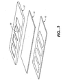
- FIG. 3 is an exploded cross-sectional view of a chamber showing the array of gel pads of a preferred embodiment of the invention.
- FIG. 4 is an exploded cross-sectional view of a port illustrating the conical shape of the port of a preferred embodiment of the invention.
- FIG. 5 is a perspective view of the label layer, the flexible, gas permeable layer and the adhesive of a preferred embodiment of the invention.
- FIG. 6 is a cross-sectional view of a preferred embodiment of the present invention illustrating the application of vacuum to a reaction chamber.
- FIG. 7 illustrates the assembly and use of a preferred embodiment of the present invention.
- the present invention provides an apparatus for performing high-capacity biological reactions on a biochip comprising a substrate having an array of biological binding sites.
- the invention also provides a method for removing gas bubbles from the apparatus.
- the invention is specifically directed to methods for removing gas bubbles from an apparatus comprising a reaction chamber having one or more arrays, preferably comprising arrays consisting of gel pads, and most preferably comprising arrays consisting of 3-dimensional polyacrylamide gel pads, wherein biological reactions are performed by reacting a biological sample containing a target molecule of interest with a complementary probe molecule immobilized on the biochip.
- array refers to an ordered spatial arrangement, particularly an arrangement of immobilized biomolecules or polymeric anchoring structures.
- addressable array refers to an array wherein the individual elements have precisely defined x and y coordinates, so that a given element at a particular position in the array can be identified.
- probe and “biomolecular probe” refer to a biomolecule used to detect a complementary biomolecule. Examples include antigens that detect antibodies, oligonucleotides that detect complimentary oligonucleotides, and ligands that detect receptors. Such probes are preferably immobilized on a substrate.
- bioarray As used herein, the terms “bioarray,” “biochip” and “biochip array” refer to an ordered spatial arrangement of immobilized biomolecules or polymeric anchoring structures on a solid supporting substrate.
- Preferred probe molecules include nucleic acids, oligonucleotides, peptides, ligands, antibodies and antigens; oligonucleotides are the most preferred probe species.
- Biochips encompass substrates containing arrays or microarrays, preferably ordered arrays and most preferably ordered, addressable arrays, of biological molecules that comprise one member of a biological binding pair.
- arrays are oligonucleotide arrays comprising a nucleotide sequence that is complementary to at least one sequence that may be or is expected to be present in a biological sample.
- peptides or other small molecules can be arrayed in such biochips for performing, inter alia, immunological analyses (wherein the arrayed molecules are antigens) or assaying biological receptors (wherein the arrayed molecules are ligands, agonists or antagonists of said receptors).
- biochips One characteristic of biochips is the manner in which the arrayed biomolecules are attached to the surface of the biochip. Conventionally such procedures involve multiple reaction steps, often requiring chemical modification of the solid support itself. Even in embodiments comprising absorption matrices, such as hydrogels, present on a solid support, chemical modification of the gel polymer is necessary to provide a chemical functionality capable forming a covalent bond with the biomolecule. The efficiency of the attachment chemistry and strength of the chemical bonds formed are critical to the fabrication and ultimate performance of the microarray.
- polyacrylamide hydrogels and gel pads are used as binding layers to adhere biological molecules to surfaces, wherein said biological molecules include but are not limited to small molecule ligands, hormomes, nutrients, metabolites, proteins, peptides, oligonucleotides, polynucleotides, and larger nucleic acid fragments.
- the gel pads for use with the apparatus of the present invention are conveniently produced as thin sheets or slabs, typically by depositing a solution in between two glass surfaces (such as glass plates or microscope slides) using a spacer to obtain the desired thickness of the polyacrylamide gel, wherein the solution comprises a monomer, most preferably an acrylamide monomer, a crosslinker such methylene bisacrylamide, a catalyst such as N,N,N′,N′-tetramethylethylendiamine (TEMED) and an initiator such as ammonium persulfate for chemical polymerization, or 2,2-dimethoxy-2-phenyl-acetophone (DMPAP) for photopolymerization.
- a monomer most preferably an acrylamide monomer, a crosslinker such methylene bisacrylamide, a catalyst such as N,N,N′,N′-tetramethylethylendiamine (TEMED) and an initiator such as ammonium persulfate for chemical polymerization, or 2,2-d
- the acrylamide monomer and crosslinker are prepared in a solution of about 4-5% acrylamide (having an acrylamide/bisacrylamide ratio of 19:1) in water/glycerol, with a small amount of initiator added.
- the solution is polymerized and crosslinked either by ultraviolet (UV) radiation (e.g., 254 nm for at least about 15 minutes, or other appropriate UV conditions, collectively termed “photopolymerization”), or by thermal initiation at elevated temperature (e.g., typically at about 40° C.).
- UV radiation e.g., 254 nm for at least about 15 minutes, or other appropriate UV conditions, collectively termed “photopolymerization”
- thermal initiation e.g., typically at about 40° C.
- the top glass slide is removed from the surface to uncover the gel.
- the pore size (and hence the “sieving properties”) of the gel can be controlled by changing the amount of crosslinker and the percent of the monomer in the polymerization solution.
- the acrylamide solution typically is imaged through a mask during the UV polymerization/crosslinking step.
- the top glass slide is removed after polymerization, and the unpolymerized monomer is washed away (developed) with water, leaving a fine feature pattern of polyacrylamide hydrogel, which is used to produce the crosslinked polyacrylamide hydrogel pads.
- light can be applied to discrete locations on the surface of a polyacrylamide hydrogel to activate these specified regions for the attachment of an oligonucleotide, an antibody, an antigen, a hormone, hormone receptor, a ligand or a polysaccharide on the surface (e.g., a polyacrylamide hydrogel surface) of a solid support (see, for example, International Application, Publication No. WO 91/07087, incorporated by reference).
- biomolecules such as oligonucleotides
- a derivatized polymer comprising the appropriate cognate chemical group.
- Covalent attachment of the biomolecule to the polymer is usually performed after polymerization and chemical cross-linking of the polymer is completed
- oligonucleotides bearing 5′-terminal acrylamide modifications can be used that efficiently copolymerize with acrylamide monomers to form DNA-containing polyacrylamide copolymers (Rehman et al., 1999 , Nucleic Acids Research 27: 649-655).
- stable probe-containing layers can be fabricated on supports (e.g., microtiter plates and silanized glass) having exposed acrylic groups. This approach has been commercially marketed as “AcryditeTM” capture probes (available from Mosaic Technologies, Boston, Mass.).
- the Acrydite moiety is a phosporamidite that contains an ethylene group capable of free-radical copolymerization with acrylamide, and which can be used in standard DNA synthesizers to introduce copolymerizable groups at the 5′ terminus of any oligonucleotide probe.
- the invention provides an apparatus 10 comprising a biochip, which itself comprises a substrate 11 having a first surface 12 and a second surface 13 opposite thereto, and a flexible, gas permeable layer 16 affixed to the first substrate surface 12 by an adhesive 15 .
- a biochip which itself comprises a substrate 11 having a first surface 12 and a second surface 13 opposite thereto, and a flexible, gas permeable layer 16 affixed to the first substrate surface 12 by an adhesive 15 .
- On the first surface 12 is an area 14 bounded by adhesive 15 and completely covered by flexible, gas permeable layer 16 .
- Flexible, gas permeable layer 16 , adhesive 15 , and first substrate surface 12 enclose a volume or reaction chamber 25 .
- the ratio of volume 25 to area 14 is preferably from about 0.025 ⁇ L/mm 2 to about 0.25 ⁇ L/mm 2 , more preferably from about 0.1 ⁇ L/mm 2 to about 0.25 ⁇ L/mm 2 , and most preferably from about 0.1 ⁇ L/mm 2 to about 0.2 ⁇ L/mm 2 .
- an array 17 of biomolecules which is preferably affixed to first substrate surface 12 , is positioned between flexible, gas permeable layer 16 and first substrate surface 12 in area 14 .
- the array comprises at least about 400, more preferably at least about 1000, and most preferably at least about 10,000 biomolecular probes.
- Array 17 most preferably further comprises gel pads 22 .
- FIG. 3 provides an exploded cross-sectional view of a portion of array 17 illustrating the gel pads 22 .
- Each gel structure 22 is preferably cylindrical, most preferably having about a diameter of about 100 microns and a thickness of about 25 microns. The distance between each site within each array 17 is most preferably about 300 microns.
- a layer of a water-soluble compound 28 having a melting point of about 30° C. to about 60° C., more preferably of about 35° C. to about 50° C., and most preferably of about 35° C. to about 45° C. is deposited in volume 25 bounded by first substrate surface 12 , flexible, gas permeable layer 16 , and adhesive 15 .
- the water-soluble compound is biocompatible, does not stick to or clog the pores of flexible, gas permeable layer 16 , and serves to prevent mechanical damage to gel pads 22 .
- the compound is polyethylene glycol, most preferably polyethylene glycol 600 .
- the compound 28 is deposited so that the entire volume 25 , with the exception of that portion of volume 25 occupied by array 17 , comprises compound 28 .
- Array 17 can be positioned on surface 12 by providing markings, most preferably holes or pits in surface 12 , that act as fiducials or reference points on surface 12 for accurate placement of array 17 .
- the presence of said fiducials is particularly advantageous in embodiments comprising a multiplicity of arrays 17 in one or a multiplicity of areas 14 on surface 12 , wherein accurate placement of said arrays is required for proper spacing and orientation of the arrays on the reaction chamber.
- Substrate 11 further comprises a first port 19 that transverses the substrate from the first surface 12 to the second surface 13 and forms first and second openings 29 and 30 on said first and second surfaces, respectively.
- the first port 19 serves as an input port and is positioned in substrate 11 . so that the first opening 29 is provided within the area 14 bounded by adhesive 15 on first surface 12 .
- substrate 11 further comprises a second port 20 that transverses the substrate from first surface 12 to second surface 13 and forms first and second openings 31 and 32 on said first and second surfaces, respectively.
- Second port 20 serves as an outlet port and is positioned in substrate 11 so that the first opening 31 opens within area 14 bounded by the adhesive 15 on the first surface 12 .
- the second openings of ports 19 and 20 are covered with a removable and replaceable cover 21 .
- replaceable cover 21 is a stopper, a gasket, or tape, most preferably foil tape.
- Input and output ports 19 and 20 are preferably shaped to accept a plastic pipette tip, most preferably a 10 ⁇ L pipette tip or a 200 ⁇ L pipette tip.
- input and output ports 19 and 20 are generally in the shape of a truncated cone, as shown in FIG. 4, wherein the end of the cone having the smaller diameter forms the first opening of each port 29 and 31 , respectively, and the end of the cone having the larger diameter forms the second opening of each port 30 and 32 , respectively.
- each port preferably has a diameter on second substrate surface 13 of from about 1.0 mm to about 2.0 mm, and a diameter on first substrate surface 12 of from about 0.3 mm to about 0.6 mm.
- the conical walls of ports 19 and 20 form an angle 54 with the second substrate surface 13 , which is preferably less than 90°. Most preferably, angle 54 is less than or equal to the contact angle 55 of the biological sample fluid 26 .
- angle 54 is equal to contact angle 55 such that the surface of the fluid in the port is flat. For aqueous solutions, this angle is about 60°. This geometric arrangement provides a port that tends not to leak, but instead wicks fluid into volume 25 so that the second substrate surface 13 is dry when replaceable cover 21 is applied.
- Substrate 11 is fabricated from any solid supporting substance, including but not limited to plastics, metals, ceramics, and glasses. Most preferably, substrate 11 is made from silicon or glass (for accuracy and stiffness), molded plastics (which reduce cost of manufacture and thermal inertia), or ceramics (for the incorporation of microfluidic elements including integrated heating elements). Most preferably, substrate 11 is glass.
- Adhesive 15 is prepared using an adhesive suitable for forming a water-tight bond between substrate 11 and flexible, gas permeable layer 16 , including, but not limited to, high temperature acrylics, rubber-based adhesives, and silicone-based adhesives.
- the shape of adhesive 15 is configured to contain array 17 .
- Adhesive 15 can be deposited on first substrate surface 12 in a pattern to produce area 14 in any desired shape, and is most preferably deposited to define an ellipsoidal area 14 .
- Adhesive 15 can be deposited using inkjet printing or offset printing methods, or by die cutting the desired shapes from a sheet of adhesive material.
- first surface 12 can be covered with adhesive and portions of the substrate which are not desired to retain adhesive properties can be hardened preferentially, for example, by ultraviolet curing.
- portions retaining adhesive properties can be defined using a mask and thereby retain adhesive properties necessary to affix flexible, gas permeable layer 16 to surface 12 .
- the adhesive material is preferably a double sided adhesive tape, and more preferably a double sided adhesive tape having no carrier.
- Adhesive 15 is most preferably set down in a layer between 1 and 100 ⁇ m thick, more preferably between 25 and 75 ⁇ m thick, and most preferably about 50 ⁇ m thick.
- Flexible, gas permeable layer 16 preferably covers an area of from about 5 mm 2 to about 1400 mm 2 , more preferably from about 5 mm 2 to about 600 mm 2 , and most preferably from about 100 mm 2 to about 600 mm 2 .
- Flexible, gas permeable layer 16 is made of any flexible solid substance, including but not limited to plastics, including polypropylene, polyethylene, and polyvinylidene chloride (sold commercially as Saran® wrap) plastics, rubbers, including silicone rubbers, high temperature polyesters, and porous Teflon®. Flexible, gas permeable layer 16 is preferably deformable, porous, and biocompatible.
- Flexible, gas permeable layer 16 also preferably impermeable to liquids in order to prevent evaporation of water from the volume contained between the flexible, gas permeable layer and the substrate.
- flexible, gas permeable layer 16 is selected to have physical, chemical and mechanical properties such that the surface tension of sample fluid 26 prevents passage of the sample fluid through the pores of the membrane, while allowing passage of gas molecules across the flexible, gas permeable layer.
- the pore size of flexible, gas permeable layer 16 is between 0.2 and 3.0 ⁇ m, more preferably between 0.2 and 1 ⁇ m, and most preferably about 0.2 ⁇ m.
- Flexible, gas permeable layer 16 also preferably is translucent and should be able to withstand temperatures of between 50° C. and 95° C. for a period of between 8 and 12 hours without shrinkage.
- the flexible, gas permeable layer is porous Teflon®. Membranes having these characteristics are available from Pall Specialty Materials.
- the invention further comprises a label layer 57 which is die cut in the same manner as the adhesive to form windows 58 that correspond in location to areas 14 on first substrate surface 12 .
- the label layer is preferably a thick film having a layer of adhesive, and most preferably is an Avery laser label.
- the label layer is applied to the outer surface of the flexible, gas permeable layer, preferably by vacuum lamination. Areas 14 are visible through windows 58 in label layer 57 .
- a means for facilitating diffusion across the flexible, gas permeable layer is removably affixed to the flexible, gas permeable layer, or the label layer when present, in order to remove gas bubbles from the reaction chambers.
- the diffusion-facilitating means creates a pressure gradient or concentration gradient across flexible, gas permeable layer 16 , thereby increasing the rate of diffusion of gas molecules from the sample fluid 26 contained in volume 25 across flexible, gas permeable layer 26 .
- a preferred embodiment of the diffusion-facilitating means, wherein the diffusion-facilitating means creates a pressure gradient across flexible, gas permeable layer 16 is shown in FIG. 6.
- a vacuum source 70 is removably affixed to flexible, gas permeable layer 16 .
- vacuum source 70 comprises a vacuum pump 71 , a chamber seal 72 that completely surrounds area 14 and is removably affixed to flexible, gas permeable layer 16 , and a length of plastic tubing 73 connecting vacuum pump 71 to reducer 72 .
- the chamber seal may be a suction cup, a reducer, or any other structure having similar chemical and mechanical properties.
- the plastic tubing is polyurethane tubing.
- the chamber seal is made of polyvinylidene fluoride (sold under the name Kynar® by Elf Atochem North America).
- Diffusion-facilitating means that create a concentration gradient across the membrane are also preferred. Concentration gradients are created, for example, by providing a flow of inert gas across flexible, gas permeable layer 16 , wherein the molecules of the inert gas are too large to pass through flexible, gas permeable layer 16 , while the gas contained in volume 25 passes freely through flexible, gas permeable layer 16 .
- Those skilled in the art will be able to select the characteristics of flexible, gas permeable layer 16 and diffusion-facilitating means that are appropriate for their selected sample fluid 26 .
- Array 17 contained in area 14 on first substrate surface 12 is covered with a water-soluble compound 28 , which protects and seals the biochip prior to use and prevents degradation or other damage to the array.
- a water-soluble compound 28 having a melting point of about 30° C. to about 60° C., more preferably of about 35° C. to about 50° C., and most preferably of about 35° C. to about 45° C. is advantageously used in filling volume 25 between array 17 and flexible, gas permeable layer 16 .
- the compound is polyethylene glycol, most preferably polyethylene glycol 600 .
- water-soluble compound 28 fills the entirety of the volume 25 and more preferably also fills at least a portion of input port 19 .
- the lack of air bubbles in volume 25 enhances efficiency of the biological reaction by ensuring that interactions, such as hybridization, between the target molecules in the sample and probe molecules comprising the array 17 or gel pads of biochip 18 are capable of proceeding without interference from such air bubbles.
- Alternative embodiments of the reaction apparatus 10 of the invention encompass a multiplicity of arrays 17 confined in a multiplicity of areas 14 underneath flexible, gas permeable layer 16 , each area comprising an array 17 and being supplied with first port 19 and, optionally, second port 20 .
- adhesive 15 is deposited on first substrate surface 12 in a pattern that defines each of areas 14 , and flexible, gas permeable layer 16 is applied to adhesive 15 to encompass areas 14 on said surface.
- reaction apparatus 10 is produced containing array 17 or a multiplicity of arrays 17 as disclosed herein, wherein the chamber is provided ready-to-use by the addition of sample fluid 26 comprising one or a multiplicity of target molecules.
- reaction apparatus 10 is provided without array 17 , and permits insertion thereof by a user. In these embodiments, at least one edge of flexible, gas permeable layer 16 is not adhered to first substrate surface 12 until array 17 is inserted.
- an amount of a sample fluid 26 is added to the reaction chamber through first port 19 .
- volume 25 is most preferably heated to a temperature greater than or equal to the melting temperature of water-soluble compound 28 .
- sample fluid 26 can be added to the chamber and mixed with the water-soluble compound, as shown in FIG. 1B.
- water-soluble compound 28 does not adversely affect the reaction taking place in the chamber. More preferably, the amount of compound 28 is chosen such that the efficiency of the biological reaction is improved when compound 28 is mixed with sample fluid 26 .
- the sample fluid is preferably introduced into the chamber after compound 28 is melted, and then the fluid is cycled into and out of the chamber, most preferably using a pipette, until fluid 26 and compound 28 are fully mixed, and the sample fluid evenly distributed over the surface of array 17 , or mixed into gel pads 22 comprising certain embodiments of said arrays.
- sample fluid 26 is evenly distributed over the surface of array 17 , or mixed into gel pads 22 by physically manipulating flexible, gas permeable layer 16 , as more fully described below.
- sample fluid 26 is removed after the reaction is completed, and array 17 is washed by the cycling a sufficient volume of a wash solution 27 into and out of the chamber, most preferably using a pipette.
- the sample fluid is preferably introduced into the chamber after compound 28 is melted, and then the fluid is cycled into and out of the chamber, most preferably using at least one pipette, until fluid 26 and compound 28 are fully mixed, and the sample fluid evenly distributed over the surface of array 17 , or mixed into gel pads 22 comprising certain embodiments of said biochips.
- Sample fluid 26 is removed after the reaction has been completed using outlet port 20 , and the biochip washed by the addition and cycling of a sufficient volume of a wash solution 27 into and out of the chamber, most preferably using a pipette.
- the wash solution can also be continuously provided by addition through the input port and removal through the output port.
- biochip 18 containing array 17 is removed from the chamber for development or further manipulations as required.
- the reaction apparatus 10 is degassed using vacuum source 70 .
- a vacuum of between 13 and 27 kPa (100 to 200 torr), more preferably a vacuum of between 13 and 20 kPa (100 to 150 torr), and most preferably a vacuum of about 13 kPa (100 torr) is applied.
- the vacuum is applied for between 10 seconds and 2 minutes, more preferably between 10 seconds and 1 minute, most preferably between 10 seconds and 30 seconds.
- Vacuum source 70 is then detached from flexible, gas permeable layer 16 , and volume 25 is visually inspected for the presence of gas bubbles.
- FIG. 7 The process of assembling a chamber according to the present invention is illustrated in FIG. 7.
- a four reaction-chamber apparatus is manufactured using a layer of 0.2 ⁇ m porous Teflon unsupported membrane as the flexible, gas permeable layer, following the procedure provided in U.S. application Ser. No. 09/464,490, incorporated by reference herein.
- Each reaction chamber is filled with 75 ⁇ L of a sample fluid containing biological target molecules by injection through a 300 ⁇ L pipette tip (VWR Part No. 53510-084) using a 200 ⁇ L pipettor (Rainin P-200). Bubbles are visually detectable in the chambers after injection.
- a reaction chamber is isolated by applying a Cole-Parmer Kynar 1 ⁇ 4′′ ⁇ 5 ⁇ 8′′ barbed reducer (Part No. 31513-31) directly to the frame layer and forming a seal around the chamber.
- a “house” vacuum source is connected to the reducer by a length of polyurethane tubing.
- a vacuum of 200 torr is applied for two minutes. Visual inspection of the chamber following application of the vacuum shows no gas bubbles remaining in the chamber.
- the reaction apparatus is maintained at 25° C. and atmospheric pressure for 8 hours until the reaction proceeds to completion. No appreciable evaporation of water from the chamber is observed.
Landscapes
- Chemical & Material Sciences (AREA)
- Health & Medical Sciences (AREA)
- Analytical Chemistry (AREA)
- General Health & Medical Sciences (AREA)
- Hematology (AREA)
- Clinical Laboratory Science (AREA)
- Chemical Kinetics & Catalysis (AREA)
- Dispersion Chemistry (AREA)
- Apparatus Associated With Microorganisms And Enzymes (AREA)
- Measuring Or Testing Involving Enzymes Or Micro-Organisms (AREA)
- Devices For Use In Laboratory Experiments (AREA)
Abstract
The present invention provides a method and an improved apparatus for removing gas bubbles from a reaction chamber comprising a flexible layer removably affixed to a substrate layer having a multiplicity of oligonucleotide binding sites disposed thereon, in which biological reactions are performed. The invention specifically relates to methods and apparatus for removing gas bubbles from a reaction chamber wherein target molecules contained in a sample fluid are reacted with probe molecules immobilized on a substrate having an array of oligonucleotide binding sites. The arrays are covered with a flexible, gas permeable layer that permits mixing of the sample fluid on the biochip and removal of gas bubbles from the fluid by use of a means for facilitating diffusion of gas bubbles across the flexible, gas permeable layer.
Description
- 1. Related Applications
- This application is a continuation-in-part of U.S. application Ser. No. 09/464,490, filed Dec. 15, 1999, which is incorporated herein by reference.
- 2. Field of the Invention
- The present invention relates to an apparatus for performing biological reactions on a substrate surface and a method for removing gas bubbles from the apparatus. Specifically, the invention relates to an apparatus having a flexible, gas permeable layer affixed to a substrate layer with an adhesive, wherein the flexible, gas permeable layer, the adhesive and the substrate layer enclose a reaction chamber, and a means for facilitating diffusion across the flexible, gas permeable layer. The diffusion-facilitating means creates a pressure gradient or concentration gradient across the flexible, gas permeable layer, thereby increasing the rate of diffusion of gas molecules from the reaction chamber across the flexible, gas permeable layer.
- 3. Description of the Prior Art
- Recent advances in molecular biology have provided the opportunity to identify pathogens, diagnose disease states, and perform forensic determinations using gene sequences specific for the desired purpose. This explosion of genetic information has created a need for high-capacity assays and equipment for performing molecular biological assays. Most urgently, there is a need to miniaturize, automate, standardize and simplify such assays. While these assays were originally developed in research laboratories working with purified products and performed by highly skilled individuals, adapting these procedures to clinical uses, such as diagnostics, forensics and other applications, has produced the need for equipment and methods that allow less-skilled operators to effectively perform the assays under higher capacity, less stringent assay conditions.
- Existing technology utilizes the binding of molecules contained within a biologically reactive sample fluid, hereinafter referred to as target molecules, onto molecules contained within biologically reactive sites, hereinafter referred to as probe molecules. The primary enabler of this technology is an apparatus commonly referred to as a biochip, which comprises one or more ordered microscopic arrays (“microarrays”) of biologically reactive sites immobilized on the surface of a substrate. A biologically reactive site can be created by dispensing a small volume of a fluid containing a biological reagent onto a discrete location on the surface of a substrate, also commonly referred to as spotting. To enhance immobilization of probe molecules, biochips can include a 2-dimensional array of 3-dimensional polymeric anchoring structures (for example, polyacrylamide gel pads) attached to the surface of the substrate. Probe molecules such as oligonucleotides are covalently attached to polyacrylamide-anchoring structures by forming amide, ester or disulfide bonds between the biomolecule and a derivatized polymer comprising the cognate chemical group. Covalent attachment of probe molecules to such polymeric anchoring structures is usually performed after polymerization and chemical cross-linking of the polymer to the substrate is completed.
- Biochips are advantageously used to perform biological reactions on the surface thereof. Existing apparatus for performing biological reactions on a substrate surface, however, are deficient in that they either require unacceptably large volumes of sample fluid to operate properly, cannot accommodate substrates as large as or larger than a conventional microscope slide, cannot independently accommodate a plurality of independent reactions, or cannot accommodate a substrate containing hydrogel-based microarrays. Most existing apparatus also do not allow introduction of fluids in addition to the sample fluid (such as wash buffers, fluorescent dyes, etc.) into the reaction chamber. Disposable apparatus must be disassembled and reassembled around the biochip every time a new fluid must be introduced. Other existing apparatus are difficult to use in a laboratory environment because they cannot be loaded with standard pipet tips and associated pipettor apparatus.
- Many existing apparatus also exhibit unacceptable reaction reproducibility, efficiency, and duration. Reaction reproducibility may be adversely affected by bubble formation in the reaction chamber or by the use of biologically incompatible materials for the reaction chamber. Reaction duration and efficiency may be adversely affected by the presence of concentration gradients in the reaction chamber.
- Bubbles can form upon introduction of sample fluid to the reaction chamber or by outgassing of the reaction chamber materials. When gas bubbles extend over the substrate surface in an area containing biologically reactive sites, the intended reaction may intermittently fail or yield erroneous results because the intended concentration of the sample fluid mixture has been compromised by the presence of gas bubbles.
- Biologically incompatible reaction chamber materials may cause unacceptable reaction reproducibility, by interacting with the sample fluid, thus causing the intended reaction to intermittently fail or yield erroneous results.
- Incomplete mixing of the sample fluid can introduce concentration gradients within the sample fluid that adversely impact reaction efficiency and duration. This effect is most pronounced when there is a depletion of target molecules in the local volume surrounding a biologically reactive site. During a biological reaction, the probability that a particular target molecule will bind to a complementary (immobilized) probe molecule is determined by the given concentration of target molecules present within the sample fluid volume, the diffusion rate of the target molecule through the reaction chamber, and the statistics of interaction between the target molecule and the complementary probe molecule. For diagnostic assays, target DNA molecules are often obtained in minute (<picomol) quantities. In practice, it can take tens of hours for a hybridization reaction to be substantially complete at the low target nucleic acid molecule levels available for biological samples. Concentration gradients in the hybridization chamber can further exacerbate this problem.
- U.S. Pat. No. 5,948,673 to Cottingham discloses a self-contained multi-chamber reactor for performing both DNA amplification and DNA probe assays in a sealed unit wherein some reactants are provided by coating the walls of the chambers and other reactants are introduced into the chambers prior to starting the reaction in order to eliminate flow into and out of the chamber. No provisions are made for eliminating gas bubbles from the chambers.
- There remains a need in the art for methods and apparatus for performing biological reactions on a substrate surface that use a low volume of sample fluid, that accommodate substrates as large as or larger than a conventional microscope slide, that accommodate a plurality of independent reactions, and that accommodate a substrate surface having one or more hydrogel-based microarrays attached thereto. There also remains a need in the art for an apparatus that allows introduction of fluids in addition to sample fluid into each reaction chamber via standard pipet tips and associated pipettor apparatus. There also remains a need in the art for such an apparatus that increases reaction reproducibility, increases reaction efficiency, and reduces reaction duration. There also remains a need in this art for a simple method for removing gas bubbles from such an apparatus. These needs are particularly striking in view of the tremendous interest in biochip technology, the investment and substantial financial rewards generated by research into biochip technology, and the variety of products generated by such research.
- The invention provides an apparatus for performing biological reactions on a substrate surface and a method for removing gas bubbles from the apparatus to prevent interference with biological reactions such as hybridization at reaction sites on the substrate surface. Specifically, the method of the invention is directed to an apparatus comprising a flexible, gas permeable layer affixed to a biochip with an adhesive, wherein the flexible, gas permeable layer, the adhesive, and the biochip enclose a reaction chamber, and a means for facilitating diffusion of gas molecules out of the reaction chamber across the flexible, gas permeable layer. The diffusion-facilitating means creates a pressure gradient or concentration gradient across the flexible, gas permeable layer, thereby increasing the rate of diffusion of gas molecules from the reaction chamber through the flexible, gas permeable layer.
- The biochip comprises a substrate having a first surface and a second surface, wherein the first surface contains an array of biologically reactive sites, and is preferably an oligonucleotide array. The array is provided in an area bounded by an adhesive set down on the first substrate surface. The flexible, gas permeable layer, the adhesive and the first substrate surface further define a volume comprising a reaction chamber.
- The flexible, gas permeable layer preferably is deformable, translucent, and porous. More preferably, the flexible, gas permeable layer is selectively permeable to gas but impermeable to liquid. Most preferably, the flexible, gas permeable layer is selectively permeable to gases and impermeable to liquids because the surface tension of the sample fluid prevents escape of the liquid through the pores of the flexible membrane.
- In certain embodiments of the invention, the substrate comprises a multiplicity of oligonucleotide arrays, which are contained in one or a plurality of areas bounded by the adhesive and covered by the flexible, gas permeable layer.
- Each of the reaction chambers also preferably include a first port, and certain embodiments further include a second port, that transverses the substrate and comprises a first opening on the first substrate surface and a second opening on the second substrate surface. The openings of these ports on the second substrate surface are covered by a removable cover, most preferably a foil tape. The openings of these ports on the first substrate surface are provided within the area bounded by the adhesive.
- The adhesive, the flexible, gas permeable layer and the substrate also enclose a reaction chamber that is filled prior to use with a water-soluble compound. The water-soluble compound is preferably a solid at a temperature most preferably at or below room temperature, and a liquid at higher temperatures, most preferably below about 100° C.
- In preferred embodiments, the diffusion-facilitating means creates a pressure differential across the flexible, gas permeable layer. In more preferred embodiments, the diffusion-facilitating means comprises a vacuum source removably affixed to the flexible, gas permeable layer, wherein the vacuum source is used to apply a vacuum to the flexible, gas permeable layer. Most preferably, the vacuum source comprises a vacuum pump connected by a length of plastic tubing to a reducer that completely encloses the area defined by the adhesive and is removably sealed to the flexible, gas permeable layer.
- The chamber is also optionally supplied with a roller, most preferably a patterned roller, positioned in contact with the flexible, gas permeable layer and movable longitudinally across the surface of the chamber for mixing sample fluid and wash solutions as required.
- Specific preferred embodiments of the present invention will become evident from the following more detailed description of certain preferred embodiments and the claims.
- Presently preferred embodiments of the invention are described with reference to the following drawings.
- FIGS. 1A-1D are views of an illustrative embodiment of the present invention illustrating the preparation of a chamber of the invention for reaction. FIG. 1A is a cross-sectional view of the apparatus illustrating a reaction chamber prefilled with a water-soluble compound. FIG. 1B is a cross-sectional view of the apparatus illustrating the mixing of the water-soluble compound and the biological sample fluid. FIG. 1C is a cross-sectional view of the apparatus illustrating a chamber filled with the sample fluid/water-soluble compound mixture, wherein the first and second ports are covered with a seal. FIG. 1D is a top plan view of the apparatus illustrating the pattern of adhesive defining the individual areas containing the arrays of oligonucleotide probes.
- FIG. 2 is an exploded perspective view of the array of biomolecular probes showing the positioning of the gel pads on the substrate of a preferred embodiment of the invention.
- FIG. 3 is an exploded cross-sectional view of a chamber showing the array of gel pads of a preferred embodiment of the invention.
- FIG. 4 is an exploded cross-sectional view of a port illustrating the conical shape of the port of a preferred embodiment of the invention.
- FIG. 5 is a perspective view of the label layer, the flexible, gas permeable layer and the adhesive of a preferred embodiment of the invention.
- FIG. 6 is a cross-sectional view of a preferred embodiment of the present invention illustrating the application of vacuum to a reaction chamber.
- FIG. 7 illustrates the assembly and use of a preferred embodiment of the present invention.
- The present invention provides an apparatus for performing high-capacity biological reactions on a biochip comprising a substrate having an array of biological binding sites. The invention also provides a method for removing gas bubbles from the apparatus. The invention is specifically directed to methods for removing gas bubbles from an apparatus comprising a reaction chamber having one or more arrays, preferably comprising arrays consisting of gel pads, and most preferably comprising arrays consisting of 3-dimensional polyacrylamide gel pads, wherein biological reactions are performed by reacting a biological sample containing a target molecule of interest with a complementary probe molecule immobilized on the biochip.
- As used herein, the term “array” refers to an ordered spatial arrangement, particularly an arrangement of immobilized biomolecules or polymeric anchoring structures.
- As used herein, the term “addressable array” refers to an array wherein the individual elements have precisely defined x and y coordinates, so that a given element at a particular position in the array can be identified.
- As used herein, the terms “probe” and “biomolecular probe” refer to a biomolecule used to detect a complementary biomolecule. Examples include antigens that detect antibodies, oligonucleotides that detect complimentary oligonucleotides, and ligands that detect receptors. Such probes are preferably immobilized on a substrate.
- As used herein, the terms “bioarray,” “biochip” and “biochip array” refer to an ordered spatial arrangement of immobilized biomolecules or polymeric anchoring structures on a solid supporting substrate. Preferred probe molecules include nucleic acids, oligonucleotides, peptides, ligands, antibodies and antigens; oligonucleotides are the most preferred probe species.
- The invention is advantageously used for performing biological reactions using biochips 18, preferably at room temperature or at slightly elevated temperatures. Biochips, as used in the art, encompass substrates containing arrays or microarrays, preferably ordered arrays and most preferably ordered, addressable arrays, of biological molecules that comprise one member of a biological binding pair. Typically, such arrays are oligonucleotide arrays comprising a nucleotide sequence that is complementary to at least one sequence that may be or is expected to be present in a biological sample. Alternatively, peptides or other small molecules can be arrayed in such biochips for performing, inter alia, immunological analyses (wherein the arrayed molecules are antigens) or assaying biological receptors (wherein the arrayed molecules are ligands, agonists or antagonists of said receptors).
- One characteristic of biochips is the manner in which the arrayed biomolecules are attached to the surface of the biochip. Conventionally such procedures involve multiple reaction steps, often requiring chemical modification of the solid support itself. Even in embodiments comprising absorption matrices, such as hydrogels, present on a solid support, chemical modification of the gel polymer is necessary to provide a chemical functionality capable forming a covalent bond with the biomolecule. The efficiency of the attachment chemistry and strength of the chemical bonds formed are critical to the fabrication and ultimate performance of the microarray.
- Preferably, polyacrylamide hydrogels and gel pads are used as binding layers to adhere biological molecules to surfaces, wherein said biological molecules include but are not limited to small molecule ligands, hormomes, nutrients, metabolites, proteins, peptides, oligonucleotides, polynucleotides, and larger nucleic acid fragments. The gel pads for use with the apparatus of the present invention are conveniently produced as thin sheets or slabs, typically by depositing a solution in between two glass surfaces (such as glass plates or microscope slides) using a spacer to obtain the desired thickness of the polyacrylamide gel, wherein the solution comprises a monomer, most preferably an acrylamide monomer, a crosslinker such methylene bisacrylamide, a catalyst such as N,N,N′,N′-tetramethylethylendiamine (TEMED) and an initiator such as ammonium persulfate for chemical polymerization, or 2,2-dimethoxy-2-phenyl-acetophone (DMPAP) for photopolymerization. Generally, the acrylamide monomer and crosslinker are prepared in a solution of about 4-5% acrylamide (having an acrylamide/bisacrylamide ratio of 19:1) in water/glycerol, with a small amount of initiator added. The solution is polymerized and crosslinked either by ultraviolet (UV) radiation (e.g., 254 nm for at least about 15 minutes, or other appropriate UV conditions, collectively termed “photopolymerization”), or by thermal initiation at elevated temperature (e.g., typically at about 40° C.). Following polymerization and crosslinking, the top glass slide is removed from the surface to uncover the gel. The pore size (and hence the “sieving properties”) of the gel can be controlled by changing the amount of crosslinker and the percent of the monomer in the polymerization solution. The pore size also can be controlled by changing the polymerization temperature.
- In the fabrication of polyacrylamide hydrogel arrays (i.e., patterned gels) used as binding layers for biological molecules, the acrylamide solution typically is imaged through a mask during the UV polymerization/crosslinking step. The top glass slide is removed after polymerization, and the unpolymerized monomer is washed away (developed) with water, leaving a fine feature pattern of polyacrylamide hydrogel, which is used to produce the crosslinked polyacrylamide hydrogel pads. Further, in an application of lithographic techniques known in the semiconductor industry, light can be applied to discrete locations on the surface of a polyacrylamide hydrogel to activate these specified regions for the attachment of an oligonucleotide, an antibody, an antigen, a hormone, hormone receptor, a ligand or a polysaccharide on the surface (e.g., a polyacrylamide hydrogel surface) of a solid support (see, for example, International Application, Publication No. WO 91/07087, incorporated by reference).
- For hydrogel-based arrays using polyacrylamide, biomolecules (such as oligonucleotides) are covalently attached by forming an amide, ester or disulfide bond between the biomolecule and a derivatized polymer comprising the appropriate cognate chemical group. Covalent attachment of the biomolecule to the polymer is usually performed after polymerization and chemical cross-linking of the polymer is completed
- Alternatively, oligonucleotides bearing 5′-terminal acrylamide modifications can be used that efficiently copolymerize with acrylamide monomers to form DNA-containing polyacrylamide copolymers (Rehman et al., 1999 , Nucleic Acids Research 27: 649-655). Using this approach, stable probe-containing layers can be fabricated on supports (e.g., microtiter plates and silanized glass) having exposed acrylic groups. This approach has been commercially marketed as “Acrydite™” capture probes (available from Mosaic Technologies, Boston, Mass.). The Acrydite moiety is a phosporamidite that contains an ethylene group capable of free-radical copolymerization with acrylamide, and which can be used in standard DNA synthesizers to introduce copolymerizable groups at the 5′ terminus of any oligonucleotide probe.
- With reference to the illustration provided in FIG. 1, the invention provides an
apparatus 10 comprising a biochip, which itself comprises asubstrate 11 having afirst surface 12 and asecond surface 13 opposite thereto, and a flexible, gaspermeable layer 16 affixed to thefirst substrate surface 12 by an adhesive 15. On thefirst surface 12 is anarea 14 bounded by adhesive 15 and completely covered by flexible, gaspermeable layer 16. Flexible, gaspermeable layer 16, adhesive 15, andfirst substrate surface 12 enclose a volume orreaction chamber 25. The ratio ofvolume 25 toarea 14 is preferably from about 0.025 μL/mm2 to about 0.25 μL/mm2, more preferably from about 0.1 μL/mm2 to about 0.25 μL/mm2, and most preferably from about 0.1 μL/mm2 to about 0.2 μL/mm2. - As shown in FIG. 2, an
array 17 of biomolecules, which is preferably affixed tofirst substrate surface 12, is positioned between flexible, gaspermeable layer 16 andfirst substrate surface 12 inarea 14. In preferred embodiments, the array comprises at least about 400, more preferably at least about 1000, and most preferably at least about 10,000 biomolecular probes.Array 17 most preferably further comprisesgel pads 22. FIG. 3 provides an exploded cross-sectional view of a portion ofarray 17 illustrating thegel pads 22. Eachgel structure 22 is preferably cylindrical, most preferably having about a diameter of about 100 microns and a thickness of about 25 microns. The distance between each site within eacharray 17 is most preferably about 300 microns. - A layer of a water-
soluble compound 28 having a melting point of about 30° C. to about 60° C., more preferably of about 35° C. to about 50° C., and most preferably of about 35° C. to about 45° C. is deposited involume 25 bounded byfirst substrate surface 12, flexible, gaspermeable layer 16, and adhesive 15. Preferably, the water-soluble compound is biocompatible, does not stick to or clog the pores of flexible, gaspermeable layer 16, and serves to prevent mechanical damage togel pads 22. In a preferred embodiment, the compound is polyethylene glycol, most preferably polyethylene glycol 600. Thecompound 28 is deposited so that theentire volume 25, with the exception of that portion ofvolume 25 occupied byarray 17, comprisescompound 28. -
Array 17 can be positioned onsurface 12 by providing markings, most preferably holes or pits insurface 12, that act as fiducials or reference points onsurface 12 for accurate placement ofarray 17. The presence of said fiducials is particularly advantageous in embodiments comprising a multiplicity ofarrays 17 in one or a multiplicity ofareas 14 onsurface 12, wherein accurate placement of said arrays is required for proper spacing and orientation of the arrays on the reaction chamber. -
Substrate 11 further comprises afirst port 19 that transverses the substrate from thefirst surface 12 to thesecond surface 13 and forms first andsecond openings first port 19 serves as an input port and is positioned insubstrate 11. so that thefirst opening 29 is provided within thearea 14 bounded by adhesive 15 onfirst surface 12. In further preferred embodiments,substrate 11 further comprises asecond port 20 that transverses the substrate fromfirst surface 12 tosecond surface 13 and forms first andsecond openings Second port 20 serves as an outlet port and is positioned insubstrate 11 so that thefirst opening 31 opens withinarea 14 bounded by the adhesive 15 on thefirst surface 12. The second openings ofports replaceable cover 21. In preferred embodiments,replaceable cover 21 is a stopper, a gasket, or tape, most preferably foil tape. - Input and
output ports output ports port port volume 25, thereby preventing potential damage to components therein, particularly the flexible, gaspermeable layer 16. In these embodiments, each port preferably has a diameter onsecond substrate surface 13 of from about 1.0 mm to about 2.0 mm, and a diameter onfirst substrate surface 12 of from about 0.3 mm to about 0.6 mm. The conical walls ofports angle 54 with thesecond substrate surface 13, which is preferably less than 90°. Most preferably,angle 54 is less than or equal to the contact angle 55 of thebiological sample fluid 26. Most preferably,angle 54 is equal to contact angle 55 such that the surface of the fluid in the port is flat. For aqueous solutions, this angle is about 60°. This geometric arrangement provides a port that tends not to leak, but instead wicks fluid intovolume 25 so that thesecond substrate surface 13 is dry whenreplaceable cover 21 is applied. -
Substrate 11 is fabricated from any solid supporting substance, including but not limited to plastics, metals, ceramics, and glasses. Most preferably,substrate 11 is made from silicon or glass (for accuracy and stiffness), molded plastics (which reduce cost of manufacture and thermal inertia), or ceramics (for the incorporation of microfluidic elements including integrated heating elements). Most preferably,substrate 11 is glass. -
Adhesive 15 is prepared using an adhesive suitable for forming a water-tight bond betweensubstrate 11 and flexible, gaspermeable layer 16, including, but not limited to, high temperature acrylics, rubber-based adhesives, and silicone-based adhesives. The shape of adhesive 15 is configured to containarray 17.Adhesive 15 can be deposited onfirst substrate surface 12 in a pattern to producearea 14 in any desired shape, and is most preferably deposited to define anellipsoidal area 14.Adhesive 15 can be deposited using inkjet printing or offset printing methods, or by die cutting the desired shapes from a sheet of adhesive material. In addition, a substantial portion offirst surface 12 can be covered with adhesive and portions of the substrate which are not desired to retain adhesive properties can be hardened preferentially, for example, by ultraviolet curing. In these embodiments, portions retaining adhesive properties can be defined using a mask and thereby retain adhesive properties necessary to affix flexible, gaspermeable layer 16 to surface 12. In embodiments using the die cut adhesive material, the adhesive material is preferably a double sided adhesive tape, and more preferably a double sided adhesive tape having no carrier.Adhesive 15 is most preferably set down in a layer between 1 and 100 μm thick, more preferably between 25 and 75 μm thick, and most preferably about 50 μm thick. - Flexible, gas
permeable layer 16 preferably covers an area of from about 5 mm2 to about 1400 mm2, more preferably from about 5 mm2 to about 600 mm2, and most preferably from about 100 mm2 to about 600 mm2. Flexible, gaspermeable layer 16 is made of any flexible solid substance, including but not limited to plastics, including polypropylene, polyethylene, and polyvinylidene chloride (sold commercially as Saran® wrap) plastics, rubbers, including silicone rubbers, high temperature polyesters, and porous Teflon®. Flexible, gaspermeable layer 16 is preferably deformable, porous, and biocompatible. Flexible, gaspermeable layer 16 also preferably impermeable to liquids in order to prevent evaporation of water from the volume contained between the flexible, gas permeable layer and the substrate. Most preferably, flexible, gaspermeable layer 16 is selected to have physical, chemical and mechanical properties such that the surface tension ofsample fluid 26 prevents passage of the sample fluid through the pores of the membrane, while allowing passage of gas molecules across the flexible, gas permeable layer. Preferably, the pore size of flexible, gaspermeable layer 16 is between 0.2 and 3.0 μm, more preferably between 0.2 and 1 μm, and most preferably about 0.2 μm. Flexible, gaspermeable layer 16 also preferably is translucent and should be able to withstand temperatures of between 50° C. and 95° C. for a period of between 8 and 12 hours without shrinkage. In a preferred embodiment, the flexible, gas permeable layer is porous Teflon®. Membranes having these characteristics are available from Pall Specialty Materials. - In preferred embodiments, as shown in FIG. 5, the invention further comprises a
label layer 57 which is die cut in the same manner as the adhesive to formwindows 58 that correspond in location toareas 14 onfirst substrate surface 12. The label layer is preferably a thick film having a layer of adhesive, and most preferably is an Avery laser label. The label layer is applied to the outer surface of the flexible, gas permeable layer, preferably by vacuum lamination.Areas 14 are visible throughwindows 58 inlabel layer 57. - A means for facilitating diffusion across the flexible, gas permeable layer is removably affixed to the flexible, gas permeable layer, or the label layer when present, in order to remove gas bubbles from the reaction chambers. The diffusion-facilitating means creates a pressure gradient or concentration gradient across flexible, gas
permeable layer 16, thereby increasing the rate of diffusion of gas molecules from thesample fluid 26 contained involume 25 across flexible, gaspermeable layer 26. A preferred embodiment of the diffusion-facilitating means, wherein the diffusion-facilitating means creates a pressure gradient across flexible, gaspermeable layer 16, is shown in FIG. 6. In this embodiment, a vacuum source 70 is removably affixed to flexible, gaspermeable layer 16. In preferred embodiments, vacuum source 70 comprises a vacuum pump 71, achamber seal 72 that completely surroundsarea 14 and is removably affixed to flexible, gaspermeable layer 16, and a length of plastic tubing 73 connecting vacuum pump 71 toreducer 72. The chamber seal may be a suction cup, a reducer, or any other structure having similar chemical and mechanical properties. Most preferably, the plastic tubing is polyurethane tubing. Most preferably the chamber seal is made of polyvinylidene fluoride (sold under the name Kynar® by Elf Atochem North America). - Diffusion-facilitating means that create a concentration gradient across the membrane are also preferred. Concentration gradients are created, for example, by providing a flow of inert gas across flexible, gas
permeable layer 16, wherein the molecules of the inert gas are too large to pass through flexible, gaspermeable layer 16, while the gas contained involume 25 passes freely through flexible, gaspermeable layer 16. Those skilled in the art will be able to select the characteristics of flexible, gaspermeable layer 16 and diffusion-facilitating means that are appropriate for their selectedsample fluid 26. -
Array 17 contained inarea 14 onfirst substrate surface 12 is covered with a water-soluble compound 28, which protects and seals the biochip prior to use and prevents degradation or other damage to the array. Any water-soluble compound 28 having a melting point of about 30° C. to about 60° C., more preferably of about 35° C. to about 50° C., and most preferably of about 35° C. to about 45° C. is advantageously used in fillingvolume 25 betweenarray 17 and flexible, gaspermeable layer 16. Preferably, the compound is polyethylene glycol, most preferably polyethylene glycol 600. It is a particularly preferred feature ofreaction apparatus 10 of the invention that water-soluble compound 28 fills the entirety of thevolume 25 and more preferably also fills at least a portion ofinput port 19. This inhibits formation of air bubbles involume 25 becausecompound 28 is first melted, then carefully mixed withsample fluid 26 withinvolume 25 using a roller 40 without producing air bubbles insample fluid 26. The lack of air bubbles involume 25 enhances efficiency of the biological reaction by ensuring that interactions, such as hybridization, between the target molecules in the sample and probe molecules comprising thearray 17 or gel pads of biochip 18 are capable of proceeding without interference from such air bubbles. - Alternative embodiments of the
reaction apparatus 10 of the invention encompass a multiplicity ofarrays 17 confined in a multiplicity ofareas 14 underneath flexible, gaspermeable layer 16, each area comprising anarray 17 and being supplied withfirst port 19 and, optionally,second port 20. In these embodiments, adhesive 15 is deposited onfirst substrate surface 12 in a pattern that defines each ofareas 14, and flexible, gaspermeable layer 16 is applied to adhesive 15 to encompassareas 14 on said surface. - In certain embodiments of the invention,
reaction apparatus 10 is produced containingarray 17 or a multiplicity ofarrays 17 as disclosed herein, wherein the chamber is provided ready-to-use by the addition ofsample fluid 26 comprising one or a multiplicity of target molecules. In alternative embodiments,reaction apparatus 10 is provided withoutarray 17, and permits insertion thereof by a user. In these embodiments, at least one edge of flexible, gaspermeable layer 16 is not adhered tofirst substrate surface 12 untilarray 17 is inserted. - In the use of the
reaction apparatus 10 of the invention, an amount of asample fluid 26, most preferably comprising a biological sample containing a target molecule, is added to the reaction chamber throughfirst port 19. Before application of thesample fluid 26 to the chamber,volume 25 is most preferably heated to a temperature greater than or equal to the melting temperature of water-soluble compound 28. When melted,sample fluid 26 can be added to the chamber and mixed with the water-soluble compound, as shown in FIG. 1B. Preferably, water-soluble compound 28 does not adversely affect the reaction taking place in the chamber. More preferably, the amount ofcompound 28 is chosen such that the efficiency of the biological reaction is improved whencompound 28 is mixed withsample fluid 26. - In embodiments of the chamber comprising
first port 19 but notsecond port 20, the sample fluid is preferably introduced into the chamber aftercompound 28 is melted, and then the fluid is cycled into and out of the chamber, most preferably using a pipette, untilfluid 26 andcompound 28 are fully mixed, and the sample fluid evenly distributed over the surface ofarray 17, or mixed intogel pads 22 comprising certain embodiments of said arrays. Alternatively,sample fluid 26 is evenly distributed over the surface ofarray 17, or mixed intogel pads 22 by physically manipulating flexible, gaspermeable layer 16, as more fully described below. In these embodiments,sample fluid 26 is removed after the reaction is completed, andarray 17 is washed by the cycling a sufficient volume of a wash solution 27 into and out of the chamber, most preferably using a pipette. - In embodiments of the chamber comprising both
first port 19 andsecond port 20, the sample fluid is preferably introduced into the chamber aftercompound 28 is melted, and then the fluid is cycled into and out of the chamber, most preferably using at least one pipette, untilfluid 26 andcompound 28 are fully mixed, and the sample fluid evenly distributed over the surface ofarray 17, or mixed intogel pads 22 comprising certain embodiments of said biochips.Sample fluid 26 is removed after the reaction has been completed usingoutlet port 20, and the biochip washed by the addition and cycling of a sufficient volume of a wash solution 27 into and out of the chamber, most preferably using a pipette. In these embodiments, the wash solution can also be continuously provided by addition through the input port and removal through the output port. In certain embodiments, biochip 18 containingarray 17 is removed from the chamber for development or further manipulations as required. - Prior to commencing the reaction, the
reaction apparatus 10 is degassed using vacuum source 70. Preferably a vacuum of between 13 and 27 kPa (100 to 200 torr), more preferably a vacuum of between 13 and 20 kPa (100 to 150 torr), and most preferably a vacuum of about 13 kPa (100 torr) is applied. Preferably the vacuum is applied for between 10 seconds and 2 minutes, more preferably between 10 seconds and 1 minute, most preferably between 10 seconds and 30 seconds. Vacuum source 70 is then detached from flexible, gaspermeable layer 16, andvolume 25 is visually inspected for the presence of gas bubbles. - The Examples that follow are illustrative of specific embodiments of the invention and various uses thereof. They are set forth for explanatory purposes only, and are not to be taken as limiting the invention.
- Removing Gas Bubbles from of a Reaction Chamber
- The process of assembling a chamber according to the present invention is illustrated in FIG. 7.
- A four reaction-chamber apparatus is manufactured using a layer of 0.2 μm porous Teflon unsupported membrane as the flexible, gas permeable layer, following the procedure provided in U.S. application Ser. No. 09/464,490, incorporated by reference herein. Each reaction chamber is filled with 75 μL of a sample fluid containing biological target molecules by injection through a 300 μL pipette tip (VWR Part No. 53510-084) using a 200 μL pipettor (Rainin P-200). Bubbles are visually detectable in the chambers after injection.
- A reaction chamber is isolated by applying a Cole-Parmer Kynar ¼″×⅝″ barbed reducer (Part No. 31513-31) directly to the frame layer and forming a seal around the chamber. A “house” vacuum source is connected to the reducer by a length of polyurethane tubing. A vacuum of 200 torr is applied for two minutes. Visual inspection of the chamber following application of the vacuum shows no gas bubbles remaining in the chamber.
- The reaction apparatus is maintained at 25° C. and atmospheric pressure for 8 hours until the reaction proceeds to completion. No appreciable evaporation of water from the chamber is observed.
- It should be understood that the foregoing disclosure emphasizes certain specific embodiments of the invention and that all modifications or alternatives equivalent thereto are within the spirit and scope of the invention as set forth in the appended claims.
Claims (10)
1. An apparatus for performing biological reactions, comprising:
(a) a substrate having a first surface and a second surface opposite thereto,
(b) an array of biomolecules positioned on the first surface of the substrate,
(c) a flexible, gas permeable layer affixed to the first surface of the substrate by an adhesive, wherein the adhesive is deposited on the first surface of the substrate and encloses an area thereupon, and wherein the flexible, gas permeable layer, the adhesive, and the first substrate surface enclose a reaction chamber;
(d) a port extending through the substrate from the first surface to the second surface thereof and having a first opening and a second opening, wherein the first opening of the port is provided within the area bounded by the adhesive and covered by the flexible, gas permeable layer and the second opening of the port is provided on the second surface of the substrate;
(e) a removable cover positioned over the second opening of the port;
(f) a layer of a water-soluble compound that is a solid at a first temperature and a liquid at a second, higher temperature, the layer being positioned in the reaction chamber between the first surface of the substrate and the flexible, gas permeable layer; and
(g) a means for facilitating diffusion of gas bubbles across the flexible, gas permeable layer, wherein the diffusion-facilitating means creates a pressure gradient or concentration gradient across the flexible, gas permeable layer thereby increasing the rate of diffusion of gas bubbles from the reaction chamber across the flexible, gas permeable layer.
2. The apparatus of claim 1 , wherein the flexible, gas permeable layer is a porous membrane.
3. The apparatus of claim 2 , wherein the porous membrane is porous Teflon.
4. The apparatus of claim 2 , wherein, when the reaction chamber contains a fluid sample, the porous membrane prevents the sample fluid from passing through the membrane.
5. The apparatus of claim 1 , wherein the means for facilitating diffusion of gas bubbles across the flexible, gas permeable layer comprises a vacuum source removably affixed to the flexible, gas permeable layer, and wherein the vacuum source is used to create a pressure gradient across the flexible, gas permeable layer to facilitate diffusion of gas bubbles from the reaction chamber across the flexible, gas permeable layer.
6. The apparatus of claim 5 , wherein the vacuum source comprises:
(a) a vacuum pump, and
(b) a chamber seal removably affixed to the flexible, gas permeable layer and removably connected to the vaccum pump, wherein the seal completely surrounds the area on the first substrate surface containing the array of biomolecules.
7. A method for removing gas bubbles from an apparatus for performing biological reactions having one or more reaction chambers bounded by a substrate layer, an adhesive and a flexible, gas permeable layer, comprising the steps of:
(a) attaching to the flexible, gas permeable layer a means for facilitating diffusion of gas molecules across the flexible, gas permeable layer, and
(b) operating the diffusion-facilitating means until the gas bubbles are removed from the reaction chamber.
8. A method for removing gas bubbles from an apparatus for performing biological reactions having one or more reaction chambers bounded by a substrate layer, an adhesive and a flexible, gas permeable layer, comprising the steps of:
(a) isolating a reaction chamber of the apparatus by applying a reducer to the flexible, gas permeable layer surrounding the reaction chamber, thereby forming a seal between the reducer and the flexible, gas permeable layer,
(b) attaching a vacuum source to the reducer, and
(c) applying a vacuum to the reaction chamber until the gas bubbles are removed from the reaction chamber.
9. In an apparatus for performing biological reactions, comprising a substrate having a first surface and a second surface opposite thereto, an array of biomolecules positioned on the first surface of the substrate, a flexible layer affixed to the first surface of the substrate by an adhesive, wherein the adhesive is deposited on the first surface of the substrate and encloses an area thereupon; a reaction chamber enclosed by the flexible layer, the adhesive and the first substrate surface; a port extending through the substrate from the first surface to the second surface thereof and having a first opening and a second opening, wherein the first opening of the port is provided within the area bounded by the adhesive and covered by the flexible layer and the second opening of the port is provided on the second surface of the substrate; a removable cover positioned over the second opening of the port; and a layer of a water-soluble compound that is a solid at a first temperature and a liquid at a second, higher temperature, the layer being positioned between the first surface of the substrate and the flexible layer, the improvement comprising
(a) a flexible layer that is a gas permeable layer and
(b) a means for facilitating diffusion of gas bubbles across the flexible, gas permeable layer, wherein the diffusion-facilitating means creates a pressure gradient or concentration gradient across the flexible, gas permeable layer such that gas bubbles diffuse from the reaction chamber to the environment outside the flexible, gas permeable layer.
10. The improvement of claim 9 , wherein the diffusion-facilitating means comprises a vacuum source removably affixed to the flexible, gas permeable layer and wherein the vacuum source is used to apply a vacuum to the flexible, gas permeable layer to remove gas bubbles from the reaction chamber.
Priority Applications (1)
| Application Number | Priority Date | Filing Date | Title |
|---|---|---|---|
| US10/394,484 US20030190744A1 (en) | 1999-12-15 | 2003-03-20 | Method and apparatus for performing biological reactions on a substrate surface |
Applications Claiming Priority (3)
| Application Number | Priority Date | Filing Date | Title |
|---|---|---|---|
| US09/464,490 US6589778B1 (en) | 1999-12-15 | 1999-12-15 | Method and apparatus for performing biological reactions on a substrate surface |
| US09/492,013 US6569674B1 (en) | 1999-12-15 | 2000-01-26 | Method and apparatus for performing biological reactions on a substrate surface |
| US10/394,484 US20030190744A1 (en) | 1999-12-15 | 2003-03-20 | Method and apparatus for performing biological reactions on a substrate surface |
Related Parent Applications (1)
| Application Number | Title | Priority Date | Filing Date |
|---|---|---|---|
| US09/492,013 Continuation US6569674B1 (en) | 1999-11-12 | 2000-01-26 | Method and apparatus for performing biological reactions on a substrate surface |
Publications (1)
| Publication Number | Publication Date |
|---|---|
| US20030190744A1 true US20030190744A1 (en) | 2003-10-09 |
Family
ID=23954585
Family Applications (2)
| Application Number | Title | Priority Date | Filing Date |
|---|---|---|---|
| US09/492,013 Expired - Fee Related US6569674B1 (en) | 1999-11-12 | 2000-01-26 | Method and apparatus for performing biological reactions on a substrate surface |
| US10/394,484 Abandoned US20030190744A1 (en) | 1999-12-15 | 2003-03-20 | Method and apparatus for performing biological reactions on a substrate surface |
Family Applications Before (1)
| Application Number | Title | Priority Date | Filing Date |
|---|---|---|---|
| US09/492,013 Expired - Fee Related US6569674B1 (en) | 1999-11-12 | 2000-01-26 | Method and apparatus for performing biological reactions on a substrate surface |
Country Status (6)
| Country | Link |
|---|---|
| US (2) | US6569674B1 (en) |
| EP (1) | EP1251963A2 (en) |
| JP (1) | JP2003520972A (en) |
| AU (2) | AU2001234593B2 (en) |
| CA (1) | CA2398271A1 (en) |
| WO (1) | WO2001054814A2 (en) |
Cited By (16)
| Publication number | Priority date | Publication date | Assignee | Title |
|---|---|---|---|---|
| US20030064507A1 (en) * | 2001-07-26 | 2003-04-03 | Sean Gallagher | System and methods for mixing within a microfluidic device |
| WO2005064309A1 (en) * | 2003-12-23 | 2005-07-14 | Ventana Medical Systems, Inc. | Method and apparatus for efficient thin film fluid |
| US20050266547A1 (en) * | 2002-09-16 | 2005-12-01 | Wilhelm Scherze | Cell culture chamber for a cell culture system |
| US20060003441A1 (en) * | 2002-09-16 | 2006-01-05 | Wilhelm Scherze | Method for cultivating cells, particularly human or animal cells |
| US20060019375A1 (en) * | 2002-09-16 | 2006-01-26 | Josef Seidl | Device for culturing cells, particularly human or animal cells |
| KR100813266B1 (en) * | 2006-09-19 | 2008-03-13 | 삼성전자주식회사 | Method for removing air bubbles from hybridization solution of a microarray-cover slip assembly and a microarray kit for the same |
| EP1963819A2 (en) * | 2005-12-22 | 2008-09-03 | Honeywell International, Inc. | Portable sample analyzer system |
| US11156603B2 (en) | 2010-04-05 | 2021-10-26 | Prognosys Biosciences, Inc. | Spatially encoded biological assays |
| US11162132B2 (en) | 2015-04-10 | 2021-11-02 | Spatial Transcriptomics Ab | Spatially distinguished, multiplex nucleic acid analysis of biological specimens |
| WO2021225900A1 (en) * | 2020-05-04 | 2021-11-11 | 10X Genomics, Inc. | Spatial transcriptomic transfer modes |
| US11208684B2 (en) | 2010-04-05 | 2021-12-28 | Prognosys Biosciences, Inc. | Spatially encoded biological assays |
| US11286515B2 (en) | 2013-06-25 | 2022-03-29 | Prognosys Biosciences, Inc. | Methods and systems for determining spatial patterns of biological targets in a sample |
| US11352659B2 (en) | 2011-04-13 | 2022-06-07 | Spatial Transcriptomics Ab | Methods of detecting analytes |
| FR3117896A1 (en) * | 2020-12-22 | 2022-06-24 | Imv Technologies | Support for microscopic analysis of a liquid-based biological substance and system comprising such a support and a microscope |
| US11624086B2 (en) | 2020-05-22 | 2023-04-11 | 10X Genomics, Inc. | Simultaneous spatio-temporal measurement of gene expression and cellular activity |
| US11733238B2 (en) | 2010-04-05 | 2023-08-22 | Prognosys Biosciences, Inc. | Spatially encoded biological assays |
Families Citing this family (59)
| Publication number | Priority date | Publication date | Assignee | Title |
|---|---|---|---|---|
| US6569674B1 (en) * | 1999-12-15 | 2003-05-27 | Amersham Biosciences Ab | Method and apparatus for performing biological reactions on a substrate surface |
| US7485454B1 (en) * | 2000-03-10 | 2009-02-03 | Bioprocessors Corp. | Microreactor |
| KR100792021B1 (en) * | 2000-03-30 | 2008-01-04 | 가부시키가이샤 에바라 세이사꾸쇼 | Reactive probe chip and method for fabrication thereof |
| US6664291B2 (en) * | 2000-03-31 | 2003-12-16 | Pfizer, Inc. | Malonamic acids and derivatives thereof as thyroid receptor ligands |
| US6867539B1 (en) * | 2000-07-12 | 2005-03-15 | 3M Innovative Properties Company | Encapsulated organic electronic devices and method for making same |
| WO2002044713A2 (en) * | 2000-11-30 | 2002-06-06 | Dot Diagnostics B.V. | Flow through device for two dimensional incubation and/or hybridization on solid supports |
| KR100916074B1 (en) * | 2001-03-09 | 2009-09-08 | 바이오마이크로 시스템즈, 인크. | Method and system for microfluidic interfacing to arrays |
| AU2002314734B2 (en) | 2001-03-30 | 2007-08-30 | Ge Healthcare Bio-Sciences Ab | P450 single nucleotide polymorphism biochip analysis |
| WO2002083852A2 (en) * | 2001-04-10 | 2002-10-24 | Bioprocessors Corporation | Microfermentor device and cell based screening method |
| US20040058407A1 (en) * | 2001-04-10 | 2004-03-25 | Miller Scott E. | Reactor systems having a light-interacting component |
| US20020195343A1 (en) * | 2001-06-20 | 2002-12-26 | Coventor, Inc. | Microfabricated separation device employing a virtual wall for interfacing fluids |
| US7179423B2 (en) * | 2001-06-20 | 2007-02-20 | Cytonome, Inc. | Microfluidic system including a virtual wall fluid interface port for interfacing fluids with the microfluidic system |
| US20020197733A1 (en) * | 2001-06-20 | 2002-12-26 | Coventor, Inc. | Microfluidic system including a virtual wall fluid interface port for interfacing fluids with the microfluidic system |
| KR100451154B1 (en) * | 2001-07-24 | 2004-10-02 | 엘지전자 주식회사 | Method for handling fluid in substrate and device for it |
| GB0128350D0 (en) * | 2001-11-27 | 2002-01-16 | Lab901 Ltd | Non-rigid apparatus for microfluidic applications |
| EP1458486B1 (en) * | 2001-12-19 | 2008-09-17 | Affymetrix, Inc. | Array plates and method for constructing array plates |
| US20050106714A1 (en) * | 2002-06-05 | 2005-05-19 | Zarur Andrey J. | Rotatable reactor systems and methods |
| US20030235521A1 (en) * | 2002-06-21 | 2003-12-25 | Shea Laurence R. | Array assay devices and methods of using the same |
| US7442342B2 (en) | 2002-06-26 | 2008-10-28 | Ge Healthcare Bio-Sciences Ab | Biochip holder and method of collecting fluid |
| EP1385006A3 (en) * | 2002-07-24 | 2004-09-01 | F. Hoffmann-La Roche Ag | System and cartridge for processing a biological sample |
| US20030157503A1 (en) * | 2003-04-04 | 2003-08-21 | Mcgarry Mark W | Compositions and methods for performing biological reactions |
| EP1628753A1 (en) * | 2003-05-30 | 2006-03-01 | Applera Corporation | Apparatus and method for hybridization and spr detection |
| WO2004112946A2 (en) * | 2003-06-05 | 2004-12-29 | Bioprocessors Corp. | Reactor with memory component |
| US20050173059A1 (en) * | 2004-02-11 | 2005-08-11 | Nalge Nunc International Corporation | Methods of making a multi-well test plate having an adhesively secured transparent bottom panel |
| DE102005052713A1 (en) * | 2005-11-04 | 2007-05-16 | Clondiag Chip Tech Gmbh | Apparatus and method for detecting molecular interactions |
| DE102004022263A1 (en) * | 2004-05-06 | 2005-12-15 | Clondiag Chip Technologies Gmbh | Apparatus and method for detecting molecular interactions |
| EP1761331A2 (en) * | 2004-06-07 | 2007-03-14 | Bioprocessors Corporation | Control of reactor environmental conditions |
| FR2860802B1 (en) * | 2004-07-28 | 2008-02-22 | Bertin Technologies Sa | METHOD FOR ENABLING CHIMILUMINESCENCE READING OF A CHIP |
| US7595157B2 (en) * | 2004-08-19 | 2009-09-29 | Biocept, Inc. | Microarrays utilizing hydrogels |
| JPWO2006123578A1 (en) * | 2005-05-19 | 2008-12-25 | コニカミノルタエムジー株式会社 | Test chip and micro total analysis system for analyzing target substances in specimens |
| US7763453B2 (en) | 2005-11-30 | 2010-07-27 | Micronics, Inc. | Microfluidic mixing and analytic apparatus |
| US9056291B2 (en) | 2005-11-30 | 2015-06-16 | Micronics, Inc. | Microfluidic reactor system |
| GB2445739A (en) | 2007-01-16 | 2008-07-23 | Lab901 Ltd | Polymeric laminates containing heat seals |
| GB0715170D0 (en) * | 2007-08-03 | 2007-09-12 | Enigma Diagnostics Ltd | Reaction vessel |
| RU2497100C2 (en) * | 2007-10-29 | 2013-10-27 | Конинклейке Филипс Электроникс Н.В. | Frustrated total internal reflection biosensor container |
| DE102008009184B4 (en) | 2008-02-15 | 2015-10-22 | Boehringer Ingelheim Vetmedica Gmbh | Device and method with a sensor array and with a stamp and their use |
| DE102008009185A1 (en) | 2008-02-15 | 2009-09-24 | Siemens Aktiengesellschaft | Apparatus and method for detecting liquids or substances from liquids and use of the apparatus |
| DE102008054313B4 (en) | 2008-11-03 | 2012-12-13 | Zenteris Gmbh | Cartridge and apparatus for assaying biological samples with temperature-controlled biological responses |
| US8501122B2 (en) | 2009-12-08 | 2013-08-06 | Affymetrix, Inc. | Manufacturing and processing polymer arrays |
| US9132423B2 (en) | 2010-01-29 | 2015-09-15 | Micronics, Inc. | Sample-to-answer microfluidic cartridge |
| WO2011129220A1 (en) * | 2010-04-14 | 2011-10-20 | 日東紡績株式会社 | Test instrument for measuring analyte in sample, and method for measuring analyte using same |
| JP5705579B2 (en) * | 2011-02-18 | 2015-04-22 | 株式会社日立ハイテクノロジーズ | Analysis equipment |
| KR102090934B1 (en) | 2012-01-09 | 2020-03-19 | 퍼킨엘머 헬스 사이언시즈, 아이엔씨. | Microfluidic reactor system |
| KR20150097764A (en) | 2012-12-21 | 2015-08-26 | 마이크로닉스 인코포레이티드. | Portable fluorescence detection system and microassay cartridge |
| CN104919191B (en) | 2012-12-21 | 2019-07-09 | 精密公司 | Fluid circuit and relevant manufacturing method |
| JP6935167B2 (en) | 2012-12-21 | 2021-09-15 | ペルキネルマー ヘルス サイエンシーズ, インコーポレイテッド | Low elasticity film for microfluidic use |
| EP2994532B1 (en) | 2013-05-07 | 2017-11-15 | Micronics, Inc. | Methods for preparation of nucleic acid-containing samples using clay minerals and alkaline solutions |
| WO2014182844A1 (en) | 2013-05-07 | 2014-11-13 | Micronics, Inc. | Microfluidic devices and methods for performing serum separation and blood cross-matching |
| EP2994543B1 (en) | 2013-05-07 | 2018-08-15 | Micronics, Inc. | Device for preparation and analysis of nucleic acids |
| JP6094393B2 (en) * | 2013-06-13 | 2017-03-15 | 住友ベークライト株式会社 | Covering body and method of using the covering body |
| CN104614517B (en) * | 2014-01-09 | 2016-03-02 | 南通大学 | The using method of dismountable microslide couveuse |
| US9845499B2 (en) * | 2016-04-04 | 2017-12-19 | Combinati Incorporated | Microfluidic siphoning array for nucleic acid quantification |
| US11285478B2 (en) | 2016-04-04 | 2022-03-29 | Combinati Incorporated | Microfluidic siphoning array for nucleic acid quantification |
| WO2018094194A1 (en) * | 2016-11-17 | 2018-05-24 | Cleveland State University | Chip platforms for microarray 3d bioprinting |
| KR102422907B1 (en) | 2016-11-17 | 2022-07-21 | 콤비네티 인코포레이티드 | Methods and systems for nucleic acid analysis and quantification |
| KR101940399B1 (en) * | 2017-04-25 | 2019-01-18 | 가톨릭대학교 산학협력단 | Medical inspection slide unit |
| US11262349B2 (en) | 2017-10-11 | 2022-03-01 | Cleveland State University | Multiplexed immune cell assays on a micropillar/microwell chip platform |
| CN113866158B (en) * | 2021-08-30 | 2024-02-09 | 上海睿钰生物科技有限公司 | Particle detection device and operation method thereof |
| US20230067319A1 (en) * | 2021-08-30 | 2023-03-02 | Shanghai Ruiyu Biotech Co., Ltd. | Particle detection device and operation method |
Citations (1)
| Publication number | Priority date | Publication date | Assignee | Title |
|---|---|---|---|---|
| US6569674B1 (en) * | 1999-12-15 | 2003-05-27 | Amersham Biosciences Ab | Method and apparatus for performing biological reactions on a substrate surface |
Family Cites Families (36)
| Publication number | Priority date | Publication date | Assignee | Title |
|---|---|---|---|---|
| US3429796A (en) * | 1965-09-16 | 1969-02-25 | Analytic Systems Co | Gas analyzer |
| US5038852A (en) | 1986-02-25 | 1991-08-13 | Cetus Corporation | Apparatus and method for performing automated amplification of nucleic acid sequences and assays using heating and cooling steps |
| US5525464A (en) | 1987-04-01 | 1996-06-11 | Hyseq, Inc. | Method of sequencing by hybridization of oligonucleotide probes |
| US5202231A (en) | 1987-04-01 | 1993-04-13 | Drmanac Radoje T | Method of sequencing of genomes by hybridization of oligonucleotide probes |
| US4908319A (en) | 1988-03-16 | 1990-03-13 | Smyczek Peter J | Laboratory apparatus |
| US5100775A (en) | 1988-03-16 | 1992-03-31 | Smyczek Peter J | Method for conducting nucleic acid hybridization in chamber with precise fluid delivery |
| US5744101A (en) | 1989-06-07 | 1998-04-28 | Affymax Technologies N.V. | Photolabile nucleoside protecting groups |
| US5527681A (en) | 1989-06-07 | 1996-06-18 | Affymax Technologies N.V. | Immobilized molecular synthesis of systematically substituted compounds |
| US5143854A (en) | 1989-06-07 | 1992-09-01 | Affymax Technologies N.V. | Large scale photolithographic solid phase synthesis of polypeptides and receptor binding screening thereof |
| JPH05501611A (en) | 1989-11-13 | 1993-03-25 | アフィマックス テクノロジーズ ナームロゼ ベノートスハップ | Spatially addressable immobilization of antiligands on surfaces |
| US5427908A (en) | 1990-05-01 | 1995-06-27 | Affymax Technologies N.V. | Recombinant library screening methods |
| US5474796A (en) | 1991-09-04 | 1995-12-12 | Protogene Laboratories, Inc. | Method and apparatus for conducting an array of chemical reactions on a support surface |
| US5541061A (en) | 1992-04-29 | 1996-07-30 | Affymax Technologies N.V. | Methods for screening factorial chemical libraries |
| US5360741A (en) | 1992-09-29 | 1994-11-01 | Triangle Biomedical Sciences, Inc. | DNA hybridization incubator |
| US5798215A (en) * | 1993-02-18 | 1998-08-25 | Biocircuits Corporation | Device for use in analyte detection assays |
| US5837832A (en) | 1993-06-25 | 1998-11-17 | Affymetrix, Inc. | Arrays of nucleic acid probes on biological chips |
| US5861242A (en) | 1993-06-25 | 1999-01-19 | Affymetrix, Inc. | Array of nucleic acid probes on biological chips for diagnosis of HIV and methods of using the same |
| US5578832A (en) | 1994-09-02 | 1996-11-26 | Affymetrix, Inc. | Method and apparatus for imaging a sample on a device |
| US5631734A (en) | 1994-02-10 | 1997-05-20 | Affymetrix, Inc. | Method and apparatus for detection of fluorescently labeled materials |
| US6015880A (en) | 1994-03-16 | 2000-01-18 | California Institute Of Technology | Method and substrate for performing multiple sequential reactions on a matrix |
| US5571639A (en) | 1994-05-24 | 1996-11-05 | Affymax Technologies N.V. | Computer-aided engineering system for design of sequence arrays and lithographic masks |
| DE69527585T2 (en) | 1994-06-08 | 2003-04-03 | Affymetrix Inc | Method and device for packaging chips |
| CA2156226C (en) * | 1994-08-25 | 1999-02-23 | Takayuki Taguchi | Biological fluid analyzing device and method |
| US5599695A (en) | 1995-02-27 | 1997-02-04 | Affymetrix, Inc. | Printing molecular library arrays using deprotection agents solely in the vapor phase |
| US5545531A (en) | 1995-06-07 | 1996-08-13 | Affymax Technologies N.V. | Methods for making a device for concurrently processing multiple biological chip assays |
| US5700924A (en) | 1995-06-07 | 1997-12-23 | Incyte Pharmaceuticals, Inc. | Serpin derived from human hypothalamus |
| US5856174A (en) | 1995-06-29 | 1999-01-05 | Affymetrix, Inc. | Integrated nucleic acid diagnostic device |
| EP1291441A3 (en) * | 1995-09-12 | 2003-03-19 | Becton, Dickinson and Company | Device and method for DNA amplification and assay |
| US5733729A (en) | 1995-09-14 | 1998-03-31 | Affymetrix, Inc. | Computer-aided probability base calling for arrays of nucleic acid probes on chips |
| US5843655A (en) | 1995-09-18 | 1998-12-01 | Affymetrix, Inc. | Methods for testing oligonucleotide arrays |
| AU1115697A (en) * | 1995-11-03 | 1997-05-22 | Sarnoff Corporation | Assay system and method for conducting assays |
| US5707860A (en) * | 1996-03-12 | 1998-01-13 | Becton Dickinson And Company | Vehicle for delivery of particles to a sample |
| US5756310A (en) | 1996-10-03 | 1998-05-26 | Incyte Pharma Inc | CDNA encoding a human phospholemman-like protein (HPLP) |
| WO1999019717A1 (en) | 1997-10-15 | 1999-04-22 | Aclara Biosciences, Inc. | Laminate microstructure device and method for making same |
| US5882930A (en) | 1997-11-10 | 1999-03-16 | Hyseq, Inc. | Reagent transfer device |
| EP1054949A4 (en) | 1998-02-20 | 2006-09-27 | Nanogen Inc | Advanced active devices and methods for molecular biological analysis and diagnostics |
-
2000
- 2000-01-26 US US09/492,013 patent/US6569674B1/en not_active Expired - Fee Related
-
2001
- 2001-01-26 WO PCT/US2001/002664 patent/WO2001054814A2/en active IP Right Grant
- 2001-01-26 EP EP01906719A patent/EP1251963A2/en not_active Withdrawn
- 2001-01-26 CA CA002398271A patent/CA2398271A1/en not_active Abandoned
- 2001-01-26 JP JP2001554789A patent/JP2003520972A/en active Pending
- 2001-01-26 AU AU2001234593A patent/AU2001234593B2/en not_active Ceased
- 2001-01-26 AU AU3459301A patent/AU3459301A/en active Pending
-
2003
- 2003-03-20 US US10/394,484 patent/US20030190744A1/en not_active Abandoned
Patent Citations (1)
| Publication number | Priority date | Publication date | Assignee | Title |
|---|---|---|---|---|
| US6569674B1 (en) * | 1999-12-15 | 2003-05-27 | Amersham Biosciences Ab | Method and apparatus for performing biological reactions on a substrate surface |
Cited By (50)
| Publication number | Priority date | Publication date | Assignee | Title |
|---|---|---|---|---|
| US20030064507A1 (en) * | 2001-07-26 | 2003-04-03 | Sean Gallagher | System and methods for mixing within a microfluidic device |
| US20050266547A1 (en) * | 2002-09-16 | 2005-12-01 | Wilhelm Scherze | Cell culture chamber for a cell culture system |
| US20060003441A1 (en) * | 2002-09-16 | 2006-01-05 | Wilhelm Scherze | Method for cultivating cells, particularly human or animal cells |
| US20060019375A1 (en) * | 2002-09-16 | 2006-01-26 | Josef Seidl | Device for culturing cells, particularly human or animal cells |
| US7635575B2 (en) | 2002-09-16 | 2009-12-22 | Pan-Biotech Gmbh | Method for cultivating cells, particularly human or animal cells |
| WO2005064309A1 (en) * | 2003-12-23 | 2005-07-14 | Ventana Medical Systems, Inc. | Method and apparatus for efficient thin film fluid |
| JP2007516447A (en) * | 2003-12-23 | 2007-06-21 | ヴェンタナ メディカル システムズ インコーポレイテッド | Method and apparatus for efficient thin film liquid treatment of flat surfaces |
| US20090253592A1 (en) * | 2003-12-23 | 2009-10-08 | Kram Brian H | Method and apparatus for treating a biological sample with a liquid reagent |
| US7615371B2 (en) | 2003-12-23 | 2009-11-10 | Ventana Medical Systems, Inc. | Method and apparatus for treating a biological sample with a liquid reagent |
| JP4871737B2 (en) * | 2003-12-23 | 2012-02-08 | ベンタナ・メデイカル・システムズ・インコーポレーテツド | Method and apparatus for efficient thin film liquid treatment of flat surfaces |
| EP1963819A2 (en) * | 2005-12-22 | 2008-09-03 | Honeywell International, Inc. | Portable sample analyzer system |
| KR100813266B1 (en) * | 2006-09-19 | 2008-03-13 | 삼성전자주식회사 | Method for removing air bubbles from hybridization solution of a microarray-cover slip assembly and a microarray kit for the same |
| US11479810B1 (en) | 2010-04-05 | 2022-10-25 | Prognosys Biosciences, Inc. | Spatially encoded biological assays |
| US11767550B2 (en) | 2010-04-05 | 2023-09-26 | Prognosys Biosciences, Inc. | Spatially encoded biological assays |
| US11732292B2 (en) | 2010-04-05 | 2023-08-22 | Prognosys Biosciences, Inc. | Spatially encoded biological assays correlating target nucleic acid to tissue section location |
| US11208684B2 (en) | 2010-04-05 | 2021-12-28 | Prognosys Biosciences, Inc. | Spatially encoded biological assays |
| US11634756B2 (en) | 2010-04-05 | 2023-04-25 | Prognosys Biosciences, Inc. | Spatially encoded biological assays |
| US11293917B2 (en) | 2010-04-05 | 2022-04-05 | Prognosys Biosciences, Inc. | Systems for analyzing target biological molecules via sample imaging and delivery of probes to substrate wells |
| US11156603B2 (en) | 2010-04-05 | 2021-10-26 | Prognosys Biosciences, Inc. | Spatially encoded biological assays |
| US11313856B2 (en) | 2010-04-05 | 2022-04-26 | Prognosys Biosciences, Inc. | Spatially encoded biological assays |
| US11560587B2 (en) | 2010-04-05 | 2023-01-24 | Prognosys Biosciences, Inc. | Spatially encoded biological assays |
| US11549138B2 (en) | 2010-04-05 | 2023-01-10 | Prognosys Biosciences, Inc. | Spatially encoded biological assays |
| US11365442B2 (en) | 2010-04-05 | 2022-06-21 | Prognosys Biosciences, Inc. | Spatially encoded biological assays |
| US11542543B2 (en) | 2010-04-05 | 2023-01-03 | Prognosys Biosciences, Inc. | System for analyzing targets of a tissue section |
| US11371086B2 (en) | 2010-04-05 | 2022-06-28 | Prognosys Biosciences, Inc. | Spatially encoded biological assays |
| US11866770B2 (en) | 2010-04-05 | 2024-01-09 | Prognosys Biosciences, Inc. | Spatially encoded biological assays |
| US11384386B2 (en) | 2010-04-05 | 2022-07-12 | Prognosys Biosciences, Inc. | Spatially encoded biological assays |
| US11761030B2 (en) | 2010-04-05 | 2023-09-19 | Prognosys Biosciences, Inc. | Spatially encoded biological assays |
| US11401545B2 (en) | 2010-04-05 | 2022-08-02 | Prognosys Biosciences, Inc. | Spatially encoded biological assays |
| US11519022B2 (en) | 2010-04-05 | 2022-12-06 | Prognosys Biosciences, Inc. | Spatially encoded biological assays |
| US11733238B2 (en) | 2010-04-05 | 2023-08-22 | Prognosys Biosciences, Inc. | Spatially encoded biological assays |
| US11479809B2 (en) | 2011-04-13 | 2022-10-25 | Spatial Transcriptomics Ab | Methods of detecting analytes |
| US11788122B2 (en) | 2011-04-13 | 2023-10-17 | 10X Genomics Sweden Ab | Methods of detecting analytes |
| US11352659B2 (en) | 2011-04-13 | 2022-06-07 | Spatial Transcriptomics Ab | Methods of detecting analytes |
| US11795498B2 (en) | 2011-04-13 | 2023-10-24 | 10X Genomics Sweden Ab | Methods of detecting analytes |
| US11359228B2 (en) | 2013-06-25 | 2022-06-14 | Prognosys Biosciences, Inc. | Methods and systems for determining spatial patterns of biological targets in a sample |
| US11618918B2 (en) | 2013-06-25 | 2023-04-04 | Prognosys Biosciences, Inc. | Methods and systems for determining spatial patterns of biological targets in a sample |
| US11753674B2 (en) | 2013-06-25 | 2023-09-12 | Prognosys Biosciences, Inc. | Methods and systems for determining spatial patterns of biological targets in a sample |
| US11286515B2 (en) | 2013-06-25 | 2022-03-29 | Prognosys Biosciences, Inc. | Methods and systems for determining spatial patterns of biological targets in a sample |
| US11821024B2 (en) | 2013-06-25 | 2023-11-21 | Prognosys Biosciences, Inc. | Methods and systems for determining spatial patterns of biological targets in a sample |
| US11613773B2 (en) | 2015-04-10 | 2023-03-28 | Spatial Transcriptomics Ab | Spatially distinguished, multiplex nucleic acid analysis of biological specimens |
| US11739372B2 (en) | 2015-04-10 | 2023-08-29 | Spatial Transcriptomics Ab | Spatially distinguished, multiplex nucleic acid analysis of biological specimens |
| US11390912B2 (en) | 2015-04-10 | 2022-07-19 | Spatial Transcriptomics Ab | Spatially distinguished, multiplex nucleic acid analysis of biological specimens |
| US11299774B2 (en) | 2015-04-10 | 2022-04-12 | Spatial Transcriptomics Ab | Spatially distinguished, multiplex nucleic acid analysis of biological specimens |
| US11162132B2 (en) | 2015-04-10 | 2021-11-02 | Spatial Transcriptomics Ab | Spatially distinguished, multiplex nucleic acid analysis of biological specimens |
| WO2021225900A1 (en) * | 2020-05-04 | 2021-11-11 | 10X Genomics, Inc. | Spatial transcriptomic transfer modes |
| US11624086B2 (en) | 2020-05-22 | 2023-04-11 | 10X Genomics, Inc. | Simultaneous spatio-temporal measurement of gene expression and cellular activity |
| US11866767B2 (en) | 2020-05-22 | 2024-01-09 | 10X Genomics, Inc. | Simultaneous spatio-temporal measurement of gene expression and cellular activity |
| WO2022136766A1 (en) * | 2020-12-22 | 2022-06-30 | Imv Technologies | Support for analysing by microscope a liquid-based biological substance and system comprising such a support and a microscope |
| FR3117896A1 (en) * | 2020-12-22 | 2022-06-24 | Imv Technologies | Support for microscopic analysis of a liquid-based biological substance and system comprising such a support and a microscope |
Also Published As
| Publication number | Publication date |
|---|---|
| CA2398271A1 (en) | 2001-08-02 |
| EP1251963A2 (en) | 2002-10-30 |
| AU3459301A (en) | 2001-08-07 |
| US6569674B1 (en) | 2003-05-27 |
| JP2003520972A (en) | 2003-07-08 |
| WO2001054814A3 (en) | 2002-02-14 |
| AU2001234593B2 (en) | 2005-09-29 |
| WO2001054814A9 (en) | 2002-10-31 |
| WO2001054814A2 (en) | 2001-08-02 |
Similar Documents
| Publication | Publication Date | Title |
|---|---|---|
| US6569674B1 (en) | Method and apparatus for performing biological reactions on a substrate surface | |
| US6589778B1 (en) | Method and apparatus for performing biological reactions on a substrate surface | |
| KR100916074B1 (en) | Method and system for microfluidic interfacing to arrays | |
| EP1773498B1 (en) | Spotting device and method for high concentration spot deposition on microarrays and other microscale devices | |
| US6642046B1 (en) | Method and apparatus for performing biological reactions on a substrate surface | |
| US20030138969A1 (en) | Closed substrate platforms suitable for analysis of biomolecules | |
| US9428800B2 (en) | Thermal cycling apparatus and method | |
| US7371348B2 (en) | Multiple array format | |
| US7919308B2 (en) | Form in place gaskets for assays | |
| US7351379B2 (en) | Fluid containment structure | |
| EP2135626B1 (en) | Strip for multiparametrics assays | |
| US20030157503A1 (en) | Compositions and methods for performing biological reactions | |
| US20050095602A1 (en) | Microfluidic integrated microarrays for biological detection | |
| US20070154942A1 (en) | Multi-array systems and methods of use thereof | |
| AU2001234593A1 (en) | Compositions and methods for performing biological reactions | |
| US20020168624A1 (en) | Well frame including connectors for biological fluids | |
| EP0891811A1 (en) | Method and apparatus for mixing a thin film of fluid | |
| JP2015511016A (en) | System and method for filling a liquid sample | |
| US20030203366A1 (en) | Microarray channel devices produced by a block mold process | |
| CA2394275A1 (en) | Apparatus for performing biological reactions | |
| US20030232344A1 (en) | Hybridization process for arrays | |
| US20060286555A1 (en) | Microarray support for bioprobe synthesis | |
| WO2003036298A2 (en) | Closed substrate platforms suitable for analysis of biomolecules | |
| JP2008134189A (en) | Probe solidifying reaction array and manufacturing method of array |
Legal Events
| Date | Code | Title | Description |
|---|---|---|---|
| STCB | Information on status: application discontinuation |
Free format text: ABANDONED -- FAILURE TO RESPOND TO AN OFFICE ACTION |