US20030190184A1 - High stability latch mechanism - Google Patents
High stability latch mechanism Download PDFInfo
- Publication number
- US20030190184A1 US20030190184A1 US10/117,256 US11725602A US2003190184A1 US 20030190184 A1 US20030190184 A1 US 20030190184A1 US 11725602 A US11725602 A US 11725602A US 2003190184 A1 US2003190184 A1 US 2003190184A1
- Authority
- US
- United States
- Prior art keywords
- cam
- lead screw
- coupler link
- latching device
- ball
- Prior art date
- Legal status (The legal status is an assumption and is not a legal conclusion. Google has not performed a legal analysis and makes no representation as to the accuracy of the status listed.)
- Granted
Links
- 230000007246 mechanism Effects 0.000 title abstract description 28
- 238000005452 bending Methods 0.000 claims description 3
- 230000003287 optical effect Effects 0.000 abstract description 10
- 239000000463 material Substances 0.000 description 9
- 230000008901 benefit Effects 0.000 description 7
- 238000000034 method Methods 0.000 description 5
- 229910001220 stainless steel Inorganic materials 0.000 description 5
- 239000010935 stainless steel Substances 0.000 description 5
- 230000000712 assembly Effects 0.000 description 3
- 238000000429 assembly Methods 0.000 description 3
- 238000006243 chemical reaction Methods 0.000 description 3
- 238000007667 floating Methods 0.000 description 3
- 230000013011 mating Effects 0.000 description 3
- 125000006850 spacer group Chemical group 0.000 description 3
- 229910001369 Brass Inorganic materials 0.000 description 2
- 229910001315 Tool steel Inorganic materials 0.000 description 2
- 239000010951 brass Substances 0.000 description 2
- 238000000576 coating method Methods 0.000 description 2
- 238000005516 engineering process Methods 0.000 description 2
- 239000000314 lubricant Substances 0.000 description 2
- 239000002184 metal Substances 0.000 description 2
- 229910052751 metal Inorganic materials 0.000 description 2
- 241001433879 Camarea Species 0.000 description 1
- 229910000760 Hardened steel Inorganic materials 0.000 description 1
- 206010023230 Joint stiffness Diseases 0.000 description 1
- RTAQQCXQSZGOHL-UHFFFAOYSA-N Titanium Chemical compound [Ti] RTAQQCXQSZGOHL-UHFFFAOYSA-N 0.000 description 1
- 230000008878 coupling Effects 0.000 description 1
- 238000010168 coupling process Methods 0.000 description 1
- 238000005859 coupling reaction Methods 0.000 description 1
- 238000006073 displacement reaction Methods 0.000 description 1
- 238000005553 drilling Methods 0.000 description 1
- 238000012544 monitoring process Methods 0.000 description 1
- 238000005457 optimization Methods 0.000 description 1
- 230000036316 preload Effects 0.000 description 1
- 230000008569 process Effects 0.000 description 1
- 230000008439 repair process Effects 0.000 description 1
- 230000035939 shock Effects 0.000 description 1
- 239000007787 solid Substances 0.000 description 1
- 238000004381 surface treatment Methods 0.000 description 1
- 239000010936 titanium Substances 0.000 description 1
- 229910052719 titanium Inorganic materials 0.000 description 1
- 238000003466 welding Methods 0.000 description 1
Images


Classifications
-
- F—MECHANICAL ENGINEERING; LIGHTING; HEATING; WEAPONS; BLASTING
- F16—ENGINEERING ELEMENTS AND UNITS; GENERAL MEASURES FOR PRODUCING AND MAINTAINING EFFECTIVE FUNCTIONING OF MACHINES OR INSTALLATIONS; THERMAL INSULATION IN GENERAL
- F16B—DEVICES FOR FASTENING OR SECURING CONSTRUCTIONAL ELEMENTS OR MACHINE PARTS TOGETHER, e.g. NAILS, BOLTS, CIRCLIPS, CLAMPS, CLIPS OR WEDGES; JOINTS OR JOINTING
- F16B21/00—Means for preventing relative axial movement of a pin, spigot, shaft or the like and a member surrounding it; Stud-and-socket releasable fastenings
- F16B21/10—Means for preventing relative axial movement of a pin, spigot, shaft or the like and a member surrounding it; Stud-and-socket releasable fastenings by separate parts
- F16B21/16—Means for preventing relative axial movement of a pin, spigot, shaft or the like and a member surrounding it; Stud-and-socket releasable fastenings by separate parts with grooves or notches in the pin or shaft
-
- G—PHYSICS
- G02—OPTICS
- G02B—OPTICAL ELEMENTS, SYSTEMS OR APPARATUS
- G02B7/00—Mountings, adjusting means, or light-tight connections, for optical elements
- G02B7/18—Mountings, adjusting means, or light-tight connections, for optical elements for prisms; for mirrors
- G02B7/182—Mountings, adjusting means, or light-tight connections, for optical elements for prisms; for mirrors for mirrors
- G02B7/1821—Mountings, adjusting means, or light-tight connections, for optical elements for prisms; for mirrors for mirrors for rotating or oscillating mirrors
-
- F—MECHANICAL ENGINEERING; LIGHTING; HEATING; WEAPONS; BLASTING
- F16—ENGINEERING ELEMENTS AND UNITS; GENERAL MEASURES FOR PRODUCING AND MAINTAINING EFFECTIVE FUNCTIONING OF MACHINES OR INSTALLATIONS; THERMAL INSULATION IN GENERAL
- F16B—DEVICES FOR FASTENING OR SECURING CONSTRUCTIONAL ELEMENTS OR MACHINE PARTS TOGETHER, e.g. NAILS, BOLTS, CIRCLIPS, CLAMPS, CLIPS OR WEDGES; JOINTS OR JOINTING
- F16B2/00—Friction-grip releasable fastenings
- F16B2/02—Clamps, i.e. with gripping action effected by positive means other than the inherent resistance to deformation of the material of the fastening
- F16B2/06—Clamps, i.e. with gripping action effected by positive means other than the inherent resistance to deformation of the material of the fastening external, i.e. with contracting action
- F16B2/10—Clamps, i.e. with gripping action effected by positive means other than the inherent resistance to deformation of the material of the fastening external, i.e. with contracting action using pivoting jaws
-
- Y—GENERAL TAGGING OF NEW TECHNOLOGICAL DEVELOPMENTS; GENERAL TAGGING OF CROSS-SECTIONAL TECHNOLOGIES SPANNING OVER SEVERAL SECTIONS OF THE IPC; TECHNICAL SUBJECTS COVERED BY FORMER USPC CROSS-REFERENCE ART COLLECTIONS [XRACs] AND DIGESTS
- Y10—TECHNICAL SUBJECTS COVERED BY FORMER USPC
- Y10T—TECHNICAL SUBJECTS COVERED BY FORMER US CLASSIFICATION
- Y10T403/00—Joints and connections
- Y10T403/32—Articulated members
- Y10T403/32606—Pivoted
- Y10T403/32631—Universal ball and socket
-
- Y—GENERAL TAGGING OF NEW TECHNOLOGICAL DEVELOPMENTS; GENERAL TAGGING OF CROSS-SECTIONAL TECHNOLOGIES SPANNING OVER SEVERAL SECTIONS OF THE IPC; TECHNICAL SUBJECTS COVERED BY FORMER USPC CROSS-REFERENCE ART COLLECTIONS [XRACs] AND DIGESTS
- Y10—TECHNICAL SUBJECTS COVERED BY FORMER USPC
- Y10T—TECHNICAL SUBJECTS COVERED BY FORMER US CLASSIFICATION
- Y10T403/00—Joints and connections
- Y10T403/59—Manually releaseable latch type
- Y10T403/591—Manually releaseable latch type having operating mechanism
-
- Y—GENERAL TAGGING OF NEW TECHNOLOGICAL DEVELOPMENTS; GENERAL TAGGING OF CROSS-SECTIONAL TECHNOLOGIES SPANNING OVER SEVERAL SECTIONS OF THE IPC; TECHNICAL SUBJECTS COVERED BY FORMER USPC CROSS-REFERENCE ART COLLECTIONS [XRACs] AND DIGESTS
- Y10—TECHNICAL SUBJECTS COVERED BY FORMER USPC
- Y10T—TECHNICAL SUBJECTS COVERED BY FORMER US CLASSIFICATION
- Y10T403/00—Joints and connections
- Y10T403/60—Biased catch or latch
- Y10T403/608—Pivoted
Definitions
- This invention relates generally to actuated mechanical interlock mechanisms and, more particularly, to high stability latching of deployable optical metering structures.
- Latching mechanisms commonly found can be categorized either as a retaining type or a mating type. Retaining types are preset in the latched position and release in their operating state. Examples of this type are illustrated in U.S. Pat. No. 4,682,804 to Palmer, et al. and U.S. Pat. No. 4,508,296 to Clark. These devices are used to retain payloads during transport, preventing damage due to shock and vibration. Remote release of the latch allows the payload to be removed from the support structure. High reliability and preload are their key performance requirements.
- Mating type latching mechanisms are illustrated in U.S. Pat. No. 4,431,333 to Chandler and U.S. Pat. No. 4,905,938 to Braccio et al., 1990. These devices have male couplings that mate with female sockets. Latching occurs after the halves are mated and serve to connect two bodies after contact. These are used to grapple satellites for repair or connection of trusses where only low tolerance alignment is necessary. Again no consideration is given to dynamic performance of the connection.
- Yet another object of the present invention is to provide a latch mechanism for use in the deployment of a segmented primary mirror comprising a plurality of petals surrounding a monolithic center segment.
- Still another object of the present invention is to provide a precision latch mechanism that can be used to interlock the metering structure of a segmented mirror once the mirror is deployed to thereby maintain mirror performance.
- the latch base is equipped with a conical seat to accept the ball, and three clamp fingers to grip the floating clamp plate once the ball is seated in the socket.
- a lead screw driven axial cam serves to drive the clamping mechanism into both a clamped and a retracted position.
- a four bar linkage is formed by the latch cam, coupler link, follower link, and seat. Once the follower link is grounded on the seat, the coupler link acts as a simple lever applying force to the clamp plate. Advantage is taken of the relatively large motion available from a four bar mechanism, as well as the mechanical advantage of a simple lever once latching is initiated. Large clamping forces generated at the interface by the coupler are reacted at the seat thereby providing high interface stiffness and linearity. No latching forces are transferred to the optical support structure.
- High interface clamping forces on the order of 1000 lbs. can be achieved with low input torque at the lead screw by choosing appropriate cam angles.
- Employing a flat cam area at the end of travel eliminates the need for accurate final cam position.
- Choosing appropriate materials can eliminate thermally induced force variation.
- End mounting the lead screw in the latch seat with a spherical bearing compensates for part tolerances, equalizing clamp finger force during latching.
- Limit sensors at extremes of cam travel and strain gauges on clamp arms can be provided to monitor operation during the latching procedure.
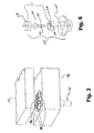
- FIGS. 1, 2 and 3 are perspective illustrations of the latching sequence of the latch mechanism of the present invention in conjunction with an exemplary deployed member and an exemplary reference structure.
- FIG. 4 is a perspective view of the latch and flexured ball assembly removed from the exemplary deployed member and the exemplary reference structure shown in FIGS. 1 through 3.
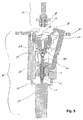
- FIG. 5 is a cross-sectional view of the latch mechanism and flexured ball assembly taken along line 5 - 5 of FIG. 4.
- FIG. 6 is an exploded perspective view of the spherical bearing assembly.
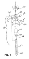
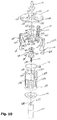
- FIG. 7 is an exploded perspective view of the lead screw/cam assembly.
- FIG. 8 is an exploded perspective view of the flexured ball assembly.
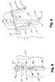
- FIG. 9 is an exploded perspective view of the linkage assembly.
- FIG. 10 is an exploded perspective view of the latch and flexured ball assembly of FIG. 4.
- FIGS. 11 a , 11 b and 11 c are simplified elevational views of the latch and flexured ball asssembly (showing only a single linkage assembly) illustrating the three basic kinematic stages of the latch operation.
- FIGS. 12 a , 12 b , 12 c , 12 d , and 12 e are simplified side elevational views of the lead screw/cam assembly in combination with a single coupler link illustrating cam/follower relationship for the five phases of the latching operation.
- FIGS. 1 through 3 there are three distinct stages which occur during the deployment operation in a large optical system.
- a single comer of a typical deployed optical system is illustrated in FIGS. 1 through 3.
- the deployed member 10 has attached to it a flexured ball assembly 12 .
- the flexured ball assembly 12 (shown in greater detail in FIGS. 4 and 8) is in alignment with the latch mechanism 14 (shown in greater detail in FIGS. 4, 5 and 10 ) which is mounted in the reference structure 16 .
- Any number of common methods can be used to maintain axial alignment.
- Latching pawls 18 are driven to their open position, providing clearance for the approaching flexured ball assembly 12 .
- the flexured ball assembly 12 makes contact with the latch mechanism 14 as shown in FIG. 2.
- Position sensing of the deployed member 10 is generally provided by an external system (not shown), and indicates when the flexured ball assembly 12 , is in its mated position with latch mechanism 14 .
- the latch mechanism 14 is actuated, which causes the latching pawls 18 to engage the flexured ball assembly 12 , as illustrated in FIG. 3.
- Applying a large force, typically about 1000 pounds, to seat the ball assembly 12 completes the latching operation.
- FIG. 4 there is shown more detailed views of the latch 14 and flexured ball assembly 12 removed from their respective structures 10 , 16 .
- Mounting plate 20 serves as the interface between the latch 14 and the reference structure 16 to which it is mounted.
- Drive motor 22 moves the latching pawls 18 in or out and supplies clamping force when the latching pawls 18 are in the latched state.
- the latch mechanism 14 is capable of locking the pawls 18 tightly in an open position as well as applying a large clamping force when the latching pawls 18 are in the fully latched position.
- the latching pawls 18 are supported within a main housing 24 to which mounting plate 20 is mounted.
- FIG. 5 there is shown a cross-sectional view of the latch mechanism 14 and flexured ball assembly 12 taken along line 5 - 5 of FIG. 4.
- latch core 26 which provides the clamping force reaction structure.
- the joint stiffness relative to the structure is controlled by the interface stiffness of mount plate 20 .
- the actual latch stiffness is controlled by the interface characteristics of the ball seat 28 , clamp plate 30 , and ball 32 . Consequently, the latch mechanism 14 and flexured ball assembly 12 are generally made of a hard material.
- FIG. 5 shows the mount plate 20 , latch core 26 , and ball seat 28 as separate elements, those skilled in the art will recognize that it is possible to combine them into a single component to reduce part count and increase stiffness.
- the spherical bearing assembly 34 (shown in an exploded view in FIG. 6) attached to the latch core 26 .
- the spherical bearing assembly 34 is comprised of a spherical bearing 36 , bearing cups 38 , and bearing housing 40 .
- the geometry of bearing cups 38 is such that when bearing housing 40 is mounted on the base of the latch core 26 (see FIG. 5), bearing cups 38 provide a running fit with the spherical bearing 36 .
- Ball stem 42 extends through an axial bore 44 in the lower bearing cup 38 and through an opening in the bearing housing 40 .
- the axial bore 44 is sized (larger than diameter of ball stem 42 ) to allow up to 15° of tilt on the ball stem 42 .
- a radial bore 46 is provided through ball stem 42 to allow for connection to the lead screw/cam assembly 48 (shown in exploded detail in FIG. 7).
- Material selection for the bearing cups 38 (typically hardened 440c stainless steel) must be different from spherical bearing 36 material (typically hardened M6 tool steel) to prevent micro welding at the contact area which can occur if lubricant migrates. Solid lubricants or low friction coatings may also be used on the contacting surfaces.
- the lead screw/cam assembly 48 is comprised of drive cam 50 , lead screw 52 , cam insert 54 , lower cam stop 56 , upper cam stop 58 , cam stop pin 60 , and anti-rotation pins 62 .
- the cam insert 54 is preferably a hardened steel material threaded to mate with the lead screw 52 that is preferably made of hardened stainless steel.
- a fine pitch thread typically 1 ⁇ 4-80, is employed to provide great mechanical advantage and axial load bearing capabilities. The fine pitch thread provides a “low ramp” adjustment of the mechanism.
- the resultant large number of threads also provides for increased mechanical engagement with the nut (cam insert) and therefore, a higher load capability.
- Other threads may be used based on available motor torque, link geometry, and required clamping force.
- Cam insert 54 is press fit into drive cam 50 and may be pinned if required for higher latch loads.
- Cam material can be of any dissimilar metal from the coupler links 64 from which pawls 18 extend. For lubricated interfaces, red brass or titanium is used. Similar materials for the drive cam 50 and coupler links 64 may be employed if low friction coatings are applied to mating surfaces.
- Lower cam stop 56 is internally threaded to match the thread of lead screw 52 . Lower cam stop 56 is positioned on the lower end of lead screw 52 to serve as a limit or travel stop for drive cam 50 when the latch is in the full open state. Once properly located, lower cam stop 56 is pinned in place to prevent axial movement when contacted.
- Upper cam stop 58 also has internal screw threads to match lead screw 52 and is positioned on the upper end to serve an upper limit or travel stop for drive cam 50 .
- Cam stop pin 60 serves to lock upper cam stop 58 in place and lock ball stem 42 of the spherical bearing assembly 34 into the end bore 66 on the lead screw 52 .
- the drive cam 50 is kept from rotating as the lead screw 52 turns via three anti-rotation pins 62 that engage the main housing 24 . Since the anti-rotation pins 62 encounter low forces, they may be made from a material dissimilar to the main housing 24 , or a low friction surface treatment may be employed.
- Lead screw 52 extends through drive cam 50 .
- the bottom of the lead screw 52 interfaces with or is otherwise coupled to the drive shaft 68 of drive motor 70 .
- Drive motor 70 is supported from motor mount 72 which is attached to the main housing 24 .
- An inward radial force is applied to the coupler links 64 by a spring element 74 , which is seated in a circumferential groove machined into the main housing 24 .
- the main housing 24 also serves as an anti-rotation surface for the drive cam 50 and as a mounting surface for the motor mount 72 .
- Lead screw/cam assembly 48 resides inside of main housing 24 and attaches to the spherical bearing assembly 34 .
- Drive cam 50 engages the actuating arms 76 of coupler links 64 to operate the latch.
- the flexured ball assembly 12 comprises a flexured stem 80 including a cylindrical mounting shaft 82 , a clamp plate retaining flange 84 , a clamp plate centering shoulder 86 , and a threaded shank 88 .
- the cylindrical mounting shaft 82 is typically mounted in an interface block attached to a bipod flexure pair (not shown).
- Three such bipod flexure pairs constitute an arrangement well known in the art as a kinematic mount.
- O-ring 90 is placed on threaded shank 88 and moved down until it meets the clamp plate retaining flange 84 .
- Clamp plate 30 is placed on the threaded shank 88 and also moved down to meet O-ring 90 .
- Ball 32 is then threaded onto threaded shank 88 and is tightened against clamp plate centering shoulder 86 .
- a diametrically located hole 92 is provided in ball 32 to allow the ball 32 to be pinned by drilling a hole through the threaded shank 88 after assembly.
- the geometry of the plate centering shoulder 86 , clamp plate inner bore 94 , clamp plate conical surface 96 , and ball 32 is such that O-ring 90 is only slightly compressed, keeping the clamp plate 30 perpendicular to the axis of flexure stem 80 , and clamp plate conical surface 96 in contact with the ball 32 .
- Clamp plate inner bore 94 is slightly larger than centering shoulder 86 allowing the clamp plate 30 to tip about the axis with only a slight force on the edge of the clamp plate 30 .
- This “floating clamp” feature prevents locking in strains due to deployment mechanism misalignment or part variations in the latch.
- Ball 32 and clamp plate 30 are preferably made from hardened 440c stainless steel since they define the clamped interface stiffness.
- Flexure stem 80 can be of any metal although a 400 series stainless steel is preferred.
- Each link 64 is part of a linkage assembly 100 shown in an exploded view in FIG. 9.
- Each linkage assembly 100 is comprised of a coupler link 64 , follower links 102 , spacers 104 , and upper pivot pin 106 .
- Upper pivot pin 106 inserts through bores 108 in follower links 102 and bore 110 in coupler link 64 as well as through spacers 104 .
- Bores 108 in follower links 102 are sized to allow a press fit of upper pivot pin 106 .
- Bore 110 in the coupler link 64 is sized as a running fit with upper pivot pin 106 .
- Spacers 104 are made of 0.010 inch thick brass and serve to prevent binding of follower links 102 with coupler link 64 after assembly.
- Each coupler link 64 has a pawl 18 that applies force to the clamp plate 30 .
- Each coupler link 64 forms a simple lever, where the lever arms are the distance from the center of the pivot bore 110 to the end of the respective pawl 18 , and from the center of the pivot bore 110 to the cam follower 116 at the ends of actuating arms 76 .
- Tab 118 is provided to allow the coupler links 64 to be drawn into the open position.
- a relief 120 in each coupler link 64 provides a pocket for residence of spring element 74 , and allows the bending stiffness of the coupler link 64 to be controlled. The bending stiffness of coupler link 64 and the amount of deflection produced by cam 50 controls the force applied to the clamp plate 30 .
- FIG. 10 An exploded view of the complete latch of the present invention is shown in FIG. 10 to illustrate the final assembly procedure.
- Internal subassemblies including the linkage assemblies 100 , lead screw/cam assembly 48 , and ball seat 28 are assembled onto the latch core 26 .
- Main pivot pins 122 are inserted through lower pivot holes 112 on the follower links 102 and main pivot holes 124 in the latch core 26 .
- Lower pivot holes 112 on the follower links 102 are a running fit with the hardened base pins 122 .
- Main pivot holes 124 in the latch core 26 provide a press fit for main pivot pins 122 .
- Ball seat 28 is also press fit into the axial bore 126 of latch core 26 .
- Clearance holes in the bearing housing 40 allow the lead screw/cam assembly 48 to be mounted to the bottom of the latch core 26 with screws.
- the assembled mechanism comprising the latch core 26 and ball seat 28 , linkage assemblies 100 , and lead screw/cam assembly 48 , is then inserted into main housing 24 .
- Mounting plate 20 is placed over the core assembly such that counter sunk screw holes 128 on the mounting plate 20 align with the clearance holes 130 on the latch core 26 , which in turn align with tapped holes 132 in the main housing 24 .
- Clearance slots 134 in the mounting plate 20 allow free movement of the linkage assemblies 100 . Coupler links 102 are then pushed into lower clearance slots 136 in the main housing 24 until they contact the surface of drive cam 50 .
- Spring element 74 (typically an O-ring) is then place around the main housing 24 to reside in a groove 138 therein to apply a radially inwardly directed force to the backs of coupler links 64 .
- Lower clearance slots 136 allow for radial and tangential motion (actually rotational motion about spherical bearing 36 ) of each coupler link 64 within the main housing 24 due to tilting of the latch control mechanism, while the sides of lower clearance slots 136 provide a reaction surface for the anti-rotation pins 62 .
- Motor mount 72 spaces the drive shaft 68 from the end of lead screw 52 .
- a drive pin 137 extending from drive shaft 68 fits loosely into a drive slot 139 in the lead screw 52 to allow angular motion at the spherical bearing 36 .
- the entire clamping mechanism is allowed to float with in the main housing 26 , allowing clamping to occur even if debris enters the system.
- FIGS. 11 a, b and c show only one linkage assembly 100 on the latch core 26 . It is assumed the flexured ball assembly 12 is seated in the latch core 26 when the latching operation begins.
- the first stage illustrated in FIG. 11 a shows the pawl 18 in its widest position, allowing clamp plate 30 of the flexured ball assembly 12 to easily move into the latch.
- Drive cam 50 on the lead screw 52 pulls the coupler link 64 into its lowest position. Contact between the drive cam 50 and coupler link 64 is maintained by the inward force from spring 74 .
- a four bar linkage is formed by the drive cam 50 , lead screw 52 , coupler link 64 , and follower link 102 in this stage.
- drive cam 50 has moved up on lead screw 52 toward the latch core 26 allowing stops 114 of the follower link 102 to contact the latch core 26 .
- the clamp plate 30 is considered captured.
- Grounding stop 114 of the follower link 102 on the latch core 26 degenerates the four bar linkage into a simple lever that is activated by the drive cam 50 .
- FIG. 11 c The end of the third stage of the latching process is illustrated in FIG. 11 c.
- the drive cam 50 has moved up to its final position on the lead screw 52 . Movement of the coupler link 64 along the drive cam 50 initiates contact of pawl 18 with the clamp ring 30 and applies the full clamping force.
- Drive cam 50 is designed to have five distinct operating regions as illustrated in FIGS. 12 a, b, c, d, e.
- the first state is shown schematically in FIG. 12 a where coupler link 64 is fully retracted, putting the latch in its open position.
- the top of drive cam 50 is equipped with a flange 140 having a lip 142 that prevents tab 118 from leaving upper cam surface 144 as it is pulled down by lead screw 52 .
- Spherical bearing 36 reacts an upward force from the lead screw 52 while spring 74 applies a radially directed force on coupler link 64 .
- Cam follower 116 is not in contact with the drive cam 50 surface.
- the third state is shown schematically in FIG. 12 c where drive cam 50 moved up further along lead screw 52 .
- Cam follower 116 has moved from the cylindrical surface 146 to the steep tapered surface 148 on drive cam 50 , while tab 118 is no longer in contact with any surface.
- Spherical bearing 36 reacts only a light upward force and spring 74 maintains a radially directed force on coupler link 64 .
- Pawls 18 are closing on the clamp plate 30 (not shown) during this stage.
- cam follower 116 reaches the end of the steep tapered surface 148 , the pawls 18 (not shown) are in contact with the clamp plate 30 (not shown).
- the fourth state is shown schematically in FIG. 12 d where drive cam 50 has moved up further along lead screw 52 almost to its final position.
- Cam follower 116 has moved from the steep tapered surface 148 to a shallow tapered surface 150 on drive cam 50 . Displacement due to the cam motion bends the coupler link 64 applying a high load on the clamp ring 30 (not shown). Spherical bearing 36 reacts a high downward force substantially greater than spring 74 .
- cam follower 116 reaches the end of the shallow tapered surface 150 , the pawls 18 (not shown) generate the maximum force on clamp plate 30 (not shown).
- Use of a shallow taper gives a large mechanical advantage while clamping, thereby reducing the required motor torque for a desired clamping force. At this point, the stop projecting from the coupler link engages the latch core when the latch plate is fully captured and final clamping begins.
Landscapes
- Engineering & Computer Science (AREA)
- General Engineering & Computer Science (AREA)
- Physics & Mathematics (AREA)
- Mechanical Engineering (AREA)
- General Physics & Mathematics (AREA)
- Optics & Photonics (AREA)
- Adjustment Of Camera Lenses (AREA)
- Pivots And Pivotal Connections (AREA)
Abstract
Description
- This invention relates generally to actuated mechanical interlock mechanisms and, more particularly, to high stability latching of deployable optical metering structures.
- To extend the range of astronomical telescopes, it is necessary to increase the effective aperture. This implies that larger diameter primary mirrors must be employed. Unfortunately, the current state of the art is at the practical size limit of monolithic mirrors. As a result, segmented primary mirrors comprising a plurality of petals surrounding a monolithic center segment must be devised. A space born telescope of this configuration will require deployment after being placed in orbit. Linear, stable, high stiffness precision latches must be used to interlock the metering structure once the mirror is deployed to maintain mirror performance. Current latching technology does not address the need for high stiffness, linearity, and precision. Latch technology as used in satellite antennae does not meet optical tolerance requirements. Their repeatability and stability are typically two orders of magnitude below optical system requirements.
- Latching mechanisms commonly found can be categorized either as a retaining type or a mating type. Retaining types are preset in the latched position and release in their operating state. Examples of this type are illustrated in U.S. Pat. No. 4,682,804 to Palmer, et al. and U.S. Pat. No. 4,508,296 to Clark. These devices are used to retain payloads during transport, preventing damage due to shock and vibration. Remote release of the latch allows the payload to be removed from the support structure. High reliability and preload are their key performance requirements.
- Mating type latching mechanisms are illustrated in U.S. Pat. No. 4,431,333 to Chandler and U.S. Pat. No. 4,905,938 to Braccio et al., 1990. These devices have male couplings that mate with female sockets. Latching occurs after the halves are mated and serve to connect two bodies after contact. These are used to grapple satellites for repair or connection of trusses where only low tolerance alignment is necessary. Again no consideration is given to dynamic performance of the connection.
- It is therefore an object of the present invention to provide a linear, stable, high stiffness precision latch mechanism.
- It is a further object of the present invention to provide a precision latch mechanism with high repeatability and stability.
- Yet another object of the present invention is to provide a latch mechanism for use in the deployment of a segmented primary mirror comprising a plurality of petals surrounding a monolithic center segment.
- Still another object of the present invention is to provide a precision latch mechanism that can be used to interlock the metering structure of a segmented mirror once the mirror is deployed to thereby maintain mirror performance.
- Briefly stated, the foregoing and numerous other features, objects and advantages of the present invention will become readily apparent upon review of the detailed description, claims and drawings set forth herein. These features, objects and advantages are accomplished by providing a high stability ball-in-cone type latch mechanism designed specifically for large deployable optical systems. It provides a nearly perfect kinematic mount between structural or optical elements and can easily be remotely controlled. Clamping force and drive position feedback can be incorporated to allow controlled closure and continuous force monitoring during and after clamping. When in the closed position, the interface consists of a ball captured between two conical surfaces. A flexured ball and floating clamp plate is typically attached to the structure being deployed. The latch base is equipped with a conical seat to accept the ball, and three clamp fingers to grip the floating clamp plate once the ball is seated in the socket. A lead screw driven axial cam serves to drive the clamping mechanism into both a clamped and a retracted position. A four bar linkage is formed by the latch cam, coupler link, follower link, and seat. Once the follower link is grounded on the seat, the coupler link acts as a simple lever applying force to the clamp plate. Advantage is taken of the relatively large motion available from a four bar mechanism, as well as the mechanical advantage of a simple lever once latching is initiated. Large clamping forces generated at the interface by the coupler are reacted at the seat thereby providing high interface stiffness and linearity. No latching forces are transferred to the optical support structure. High interface clamping forces on the order of 1000 lbs. can be achieved with low input torque at the lead screw by choosing appropriate cam angles. Employing a flat cam area at the end of travel eliminates the need for accurate final cam position. Choosing appropriate materials can eliminate thermally induced force variation. End mounting the lead screw in the latch seat with a spherical bearing compensates for part tolerances, equalizing clamp finger force during latching. Limit sensors at extremes of cam travel and strain gauges on clamp arms can be provided to monitor operation during the latching procedure.
- FIGS. 1, 2 and 3 are perspective illustrations of the latching sequence of the latch mechanism of the present invention in conjunction with an exemplary deployed member and an exemplary reference structure.
- FIG. 4 is a perspective view of the latch and flexured ball assembly removed from the exemplary deployed member and the exemplary reference structure shown in FIGS. 1 through 3.
- FIG. 5 is a cross-sectional view of the latch mechanism and flexured ball assembly taken along line 5-5 of FIG. 4.
- FIG. 6 is an exploded perspective view of the spherical bearing assembly.
- FIG. 7 is an exploded perspective view of the lead screw/cam assembly.
- FIG. 8 is an exploded perspective view of the flexured ball assembly.
- FIG. 9 is an exploded perspective view of the linkage assembly.
- FIG. 10 is an exploded perspective view of the latch and flexured ball assembly of FIG. 4.
- FIGS. 11 a, 11 b and 11 c are simplified elevational views of the latch and flexured ball asssembly (showing only a single linkage assembly) illustrating the three basic kinematic stages of the latch operation.
- FIGS. 12 a, 12 b, 12 c, 12 d, and 12 e are simplified side elevational views of the lead screw/cam assembly in combination with a single coupler link illustrating cam/follower relationship for the five phases of the latching operation.
- To facilitate understanding, identical reference numerals have been used, where possible, to designate identical elements that are common to the figures.
- Referring to FIGS. 1 through 3 there are three distinct stages which occur during the deployment operation in a large optical system. A single comer of a typical deployed optical system is illustrated in FIGS. 1 through 3. During the first stage as illustrated in FIG. 1, the deployed
member 10 has attached to it aflexured ball assembly 12. The flexured ball assembly 12 (shown in greater detail in FIGS. 4 and 8) is in alignment with the latch mechanism 14 (shown in greater detail in FIGS. 4, 5 and 10) which is mounted in thereference structure 16. Any number of common methods can be used to maintain axial alignment. Latchingpawls 18 are driven to their open position, providing clearance for the approachingflexured ball assembly 12. As deployment proceeds, theflexured ball assembly 12, makes contact with thelatch mechanism 14 as shown in FIG. 2. Position sensing of the deployedmember 10 is generally provided by an external system (not shown), and indicates when theflexured ball assembly 12, is in its mated position withlatch mechanism 14. At this point thelatch mechanism 14 is actuated, which causes the latchingpawls 18 to engage theflexured ball assembly 12, as illustrated in FIG. 3. Applying a large force, typically about 1000 pounds, to seat theball assembly 12 completes the latching operation. - Turning to FIG. 4 there is shown more detailed views of the
latch 14 andflexured ball assembly 12 removed from theirrespective structures plate 20 serves as the interface between thelatch 14 and thereference structure 16 to which it is mounted. Drivemotor 22 moves the latchingpawls 18 in or out and supplies clamping force when the latchingpawls 18 are in the latched state. Thelatch mechanism 14 is capable of locking thepawls 18 tightly in an open position as well as applying a large clamping force when the latchingpawls 18 are in the fully latched position. The latchingpawls 18 are supported within amain housing 24 to which mountingplate 20 is mounted. - Referring next to FIG. 5 there is shown a cross-sectional view of the
latch mechanism 14 andflexured ball assembly 12 taken along line 5-5 of FIG. 4. Residing within and attached tomain housing 24 islatch core 26 which provides the clamping force reaction structure. The joint stiffness relative to the structure is controlled by the interface stiffness ofmount plate 20. The actual latch stiffness is controlled by the interface characteristics of theball seat 28,clamp plate 30, andball 32. Consequently, thelatch mechanism 14 andflexured ball assembly 12 are generally made of a hard material. Although FIG. 5 shows themount plate 20,latch core 26, andball seat 28 as separate elements, those skilled in the art will recognize that it is possible to combine them into a single component to reduce part count and increase stiffness. - Still referring to FIG. 5, there is a spherical bearing assembly 34 (shown in an exploded view in FIG. 6) attached to the
latch core 26. Thespherical bearing assembly 34 is comprised of aspherical bearing 36, bearing cups 38, and bearinghousing 40. The geometry of bearingcups 38 is such that when bearinghousing 40 is mounted on the base of the latch core 26 (see FIG. 5), bearing cups 38 provide a running fit with thespherical bearing 36.Ball stem 42 extends through an axial bore 44 in thelower bearing cup 38 and through an opening in the bearinghousing 40. The axial bore 44 is sized (larger than diameter of ball stem 42) to allow up to 15° of tilt on the ball stem 42. A radial bore 46 is provided through ball stem 42 to allow for connection to the lead screw/cam assembly 48 (shown in exploded detail in FIG. 7). Material selection for the bearing cups 38 (typically hardened 440c stainless steel) must be different fromspherical bearing 36 material (typically hardened M6 tool steel) to prevent micro welding at the contact area which can occur if lubricant migrates. Solid lubricants or low friction coatings may also be used on the contacting surfaces. - The lead screw/
cam assembly 48 is comprised ofdrive cam 50,lead screw 52, cam insert 54,lower cam stop 56,upper cam stop 58,cam stop pin 60, and anti-rotation pins 62. The cam insert 54 is preferably a hardened steel material threaded to mate with thelead screw 52 that is preferably made of hardened stainless steel. A fine pitch thread, typically ¼-80, is employed to provide great mechanical advantage and axial load bearing capabilities. The fine pitch thread provides a “low ramp” adjustment of the mechanism. The resultant large number of threads also provides for increased mechanical engagement with the nut (cam insert) and therefore, a higher load capability. Other threads may be used based on available motor torque, link geometry, and required clamping force. Optimization methods for these mechanisms are well known in the art. Cam insert 54 is press fit intodrive cam 50 and may be pinned if required for higher latch loads. Cam material can be of any dissimilar metal from the coupler links 64 from which pawls 18 extend. For lubricated interfaces, red brass or titanium is used. Similar materials for thedrive cam 50 andcoupler links 64 may be employed if low friction coatings are applied to mating surfaces.Lower cam stop 56 is internally threaded to match the thread oflead screw 52.Lower cam stop 56 is positioned on the lower end oflead screw 52 to serve as a limit or travel stop fordrive cam 50 when the latch is in the full open state. Once properly located,lower cam stop 56 is pinned in place to prevent axial movement when contacted.Upper cam stop 58 also has internal screw threads to matchlead screw 52 and is positioned on the upper end to serve an upper limit or travel stop fordrive cam 50.Cam stop pin 60 serves to lockupper cam stop 58 in place and lock ball stem 42 of thespherical bearing assembly 34 into the end bore 66 on thelead screw 52. Thedrive cam 50 is kept from rotating as thelead screw 52 turns via threeanti-rotation pins 62 that engage themain housing 24. Since the anti-rotation pins 62 encounter low forces, they may be made from a material dissimilar to themain housing 24, or a low friction surface treatment may be employed. -
Lead screw 52 extends throughdrive cam 50. The bottom of thelead screw 52 interfaces with or is otherwise coupled to thedrive shaft 68 ofdrive motor 70. Drivemotor 70 is supported frommotor mount 72 which is attached to themain housing 24. An inward radial force is applied to the coupler links 64 by aspring element 74, which is seated in a circumferential groove machined into themain housing 24. Themain housing 24 also serves as an anti-rotation surface for thedrive cam 50 and as a mounting surface for themotor mount 72. Lead screw/cam assembly 48 resides inside ofmain housing 24 and attaches to thespherical bearing assembly 34. Drivecam 50 engages the actuatingarms 76 ofcoupler links 64 to operate the latch. - An exploded view of the
flexured ball assembly 12 is shown in FIG. 8. Theflexured ball assembly 12 comprises a flexured stem 80 including a cylindrical mountingshaft 82, a clampplate retaining flange 84, a clampplate centering shoulder 86, and a threadedshank 88. The cylindrical mountingshaft 82 is typically mounted in an interface block attached to a bipod flexure pair (not shown). Three such bipod flexure pairs constitute an arrangement well known in the art as a kinematic mount. O-ring 90 is placed on threadedshank 88 and moved down until it meets the clampplate retaining flange 84.Clamp plate 30 is placed on the threadedshank 88 and also moved down to meet O-ring 90.Ball 32 is then threaded onto threadedshank 88 and is tightened against clampplate centering shoulder 86. A diametrically locatedhole 92 is provided inball 32 to allow theball 32 to be pinned by drilling a hole through the threadedshank 88 after assembly. The geometry of theplate centering shoulder 86, clamp plate inner bore 94, clamp plateconical surface 96, andball 32, is such that O-ring 90 is only slightly compressed, keeping theclamp plate 30 perpendicular to the axis of flexure stem 80, and clamp plateconical surface 96 in contact with theball 32. Clamp plate inner bore 94 is slightly larger than centeringshoulder 86 allowing theclamp plate 30 to tip about the axis with only a slight force on the edge of theclamp plate 30. This “floating clamp” feature prevents locking in strains due to deployment mechanism misalignment or part variations in the latch.Ball 32 andclamp plate 30 are preferably made from hardened 440c stainless steel since they define the clamped interface stiffness. Flexure stem 80 can be of any metal although a 400 series stainless steel is preferred. - Each
link 64 is part of alinkage assembly 100 shown in an exploded view in FIG. 9. Eachlinkage assembly 100 is comprised of acoupler link 64, follower links 102,spacers 104, andupper pivot pin 106.Upper pivot pin 106 inserts through bores 108 infollower links 102 and bore 110 incoupler link 64 as well as throughspacers 104. Bores 108 infollower links 102 are sized to allow a press fit ofupper pivot pin 106.Bore 110 in thecoupler link 64 is sized as a running fit withupper pivot pin 106.Spacers 104 are made of 0.010 inch thick brass and serve to prevent binding offollower links 102 withcoupler link 64 after assembly. High stresses infollower links 104 andcoupler link 64 in the regions of thebores 108, 110 require these to be made of a high tensile strength material such as hardened 440c stainless steel. Similarly thepivot pin 106 is precision ground hardened tool steel. Lower pivot bores 112 must be aligned during assembly to allowkinematic stops 114 to properly interface with thelatch core 26. Eachcoupler link 64 has apawl 18 that applies force to theclamp plate 30. Each coupler link 64 forms a simple lever, where the lever arms are the distance from the center of the pivot bore 110 to the end of therespective pawl 18, and from the center of the pivot bore 110 to thecam follower 116 at the ends of actuatingarms 76.Tab 118 is provided to allow the coupler links 64 to be drawn into the open position. Arelief 120 in eachcoupler link 64 provides a pocket for residence ofspring element 74, and allows the bending stiffness of thecoupler link 64 to be controlled. The bending stiffness ofcoupler link 64 and the amount of deflection produced bycam 50 controls the force applied to theclamp plate 30. - An exploded view of the complete latch of the present invention is shown in FIG. 10 to illustrate the final assembly procedure. Internal subassemblies including the
linkage assemblies 100, lead screw/cam assembly 48, andball seat 28 are assembled onto thelatch core 26. Main pivot pins 122 are inserted through lower pivot holes 112 on the follower links 102 and main pivot holes 124 in thelatch core 26. Lower pivot holes 112 on the follower links 102 are a running fit with the hardened base pins 122. Main pivot holes 124 in thelatch core 26 provide a press fit for main pivot pins 122.Ball seat 28 is also press fit into the axial bore 126 oflatch core 26. Clearance holes in the bearinghousing 40 allow the lead screw/cam assembly 48 to be mounted to the bottom of thelatch core 26 with screws. The assembled mechanism comprising thelatch core 26 andball seat 28,linkage assemblies 100, and lead screw/cam assembly 48, is then inserted intomain housing 24. Mountingplate 20 is placed over the core assembly such that counter sunkscrew holes 128 on the mountingplate 20 align with the clearance holes 130 on thelatch core 26, which in turn align with tappedholes 132 in themain housing 24.Clearance slots 134 in the mountingplate 20 allow free movement of thelinkage assemblies 100.Coupler links 102 are then pushed intolower clearance slots 136 in themain housing 24 until they contact the surface ofdrive cam 50. Spring element 74 (typically an O-ring) is then place around themain housing 24 to reside in agroove 138 therein to apply a radially inwardly directed force to the backs of coupler links 64.Lower clearance slots 136 allow for radial and tangential motion (actually rotational motion about spherical bearing 36) of eachcoupler link 64 within themain housing 24 due to tilting of the latch control mechanism, while the sides oflower clearance slots 136 provide a reaction surface for the anti-rotation pins 62. Motor mount 72 spaces thedrive shaft 68 from the end oflead screw 52. Preferably, adrive pin 137 extending fromdrive shaft 68 fits loosely into adrive slot 139 in thelead screw 52 to allow angular motion at thespherical bearing 36. The entire clamping mechanism is allowed to float with in themain housing 26, allowing clamping to occur even if debris enters the system. - To better understand the functions of the individual latch parts, it is necessary to understand the basic kinematic stages of the latching operation. These are illustrated schematically in FIGS. 11 a, b and c, by showing only one
linkage assembly 100 on thelatch core 26. It is assumed theflexured ball assembly 12 is seated in thelatch core 26 when the latching operation begins. The first stage illustrated in FIG. 11a shows thepawl 18 in its widest position, allowingclamp plate 30 of theflexured ball assembly 12 to easily move into the latch. Drivecam 50 on thelead screw 52 pulls thecoupler link 64 into its lowest position. Contact between thedrive cam 50 andcoupler link 64 is maintained by the inward force fromspring 74. A four bar linkage is formed by thedrive cam 50,lead screw 52,coupler link 64, and follower link 102 in this stage. In the second stage illustrated in FIG. 11b,drive cam 50 has moved up onlead screw 52 toward thelatch core 26 allowingstops 114 of thefollower link 102 to contact thelatch core 26. At this point theclamp plate 30 is considered captured. Although no force is being applied, theflexured ball assembly 12 cannot move out of the capture range of the latch. Groundingstop 114 of the follower link 102 on thelatch core 26 degenerates the four bar linkage into a simple lever that is activated by thedrive cam 50. The end of the third stage of the latching process is illustrated in FIG. 11c. Here thedrive cam 50 has moved up to its final position on thelead screw 52. Movement of thecoupler link 64 along thedrive cam 50 initiates contact ofpawl 18 with theclamp ring 30 and applies the full clamping force. -
Drive cam 50 is designed to have five distinct operating regions as illustrated in FIGS. 12a, b, c, d, e. The first state is shown schematically in FIG. 12a where coupler link 64 is fully retracted, putting the latch in its open position. The top ofdrive cam 50 is equipped with aflange 140 having alip 142 that preventstab 118 from leavingupper cam surface 144 as it is pulled down bylead screw 52.Spherical bearing 36 reacts an upward force from thelead screw 52 whilespring 74 applies a radially directed force oncoupler link 64.Cam follower 116 is not in contact with thedrive cam 50 surface. - The second state is shown schematically in FIG. 12 b where
drive cam 50 has moved up on thelead screw 52 to a point wheretab 118 is still in contact withupper cam surface 144 but has moved in radially fromlip 142.Cam follower 116 is now in contact with thecylindrical surface 146 of thedrive cam 50. Contact betweencoupler link 64 andcylindrical surface 146 is maintained byspring 74 only. A slight downward force is applied to thespherical bearing 36 bylead screw 52. The four bar linkage degenerates into a simple lever at this stage since the follower link 102 (not shown) is grounded to the latch core 26 (not shown). - The third state is shown schematically in FIG. 12 c where
drive cam 50 moved up further alonglead screw 52.Cam follower 116 has moved from thecylindrical surface 146 to the steep taperedsurface 148 ondrive cam 50, whiletab 118 is no longer in contact with any surface.Spherical bearing 36 reacts only a light upward force andspring 74 maintains a radially directed force oncoupler link 64. Pawls 18 (not shown) are closing on the clamp plate 30 (not shown) during this stage. Whencam follower 116 reaches the end of the steep taperedsurface 148, the pawls 18 (not shown) are in contact with the clamp plate 30 (not shown). - The fourth state is shown schematically in FIG. 12 d where
drive cam 50 has moved up further alonglead screw 52 almost to its final position.Cam follower 116 has moved from the steep taperedsurface 148 to a shallow taperedsurface 150 ondrive cam 50. Displacement due to the cam motion bends thecoupler link 64 applying a high load on the clamp ring 30 (not shown).Spherical bearing 36 reacts a high downward force substantially greater thanspring 74. Whencam follower 116 reaches the end of the shallow taperedsurface 150, the pawls 18 (not shown) generate the maximum force on clamp plate 30 (not shown). Use of a shallow taper gives a large mechanical advantage while clamping, thereby reducing the required motor torque for a desired clamping force. At this point, the stop projecting from the coupler link engages the latch core when the latch plate is fully captured and final clamping begins. - The final state is shown schematically in FIG. 12 e where
drive cam 50 has reached its final position onlead screw 52.Cam follower 116 has moved from the shallow taperedsurface 150 to a lowercylindrical surface 152 ondrive cam 50. No changes in reaction forces are seen since thecoupler link 64 has experienced no further deflection on the lowercylindrical surface 152 than that seen at the end of the shallow taperedsurface 150. This eliminates the need to have a precise stopping point for the motor and allows motor slip to occur with out changing the clamping force. - From the foregoing, it will be seen that this invention is one well adapted to obtain all of the ends and objects hereinabove set forth together with other advantages which are apparent and which are inherent to the apparatus.
- It will be understood that certain features and sub-combinations are of utility and may be employed with reference to other features and sub-combinations. This is contemplated by and is within the scope of the claims.
- As many possible embodiments may be made of the invention without departing from the scope thereof, it is to be understood that all matter herein set forth and shown in the accompanying drawings is to be interpreted as illustrative and not in a limiting sense.
- 10 deployed member
- 12 flexured ball assembly
- 14 latch mechanism
- 16 reference structure
- 18 pawls
- 20 mounting plate
- 22 drive motor
- 24 main housing
- 26 latch core
- 28 ball seat
- 30 clamp plate
- 32 ball
- 34 spherical bearing assembly
- 36 spherical bearing
- 38 bearing clips
- 40 bearing housing
- 42 ball stem
- 44 axial bore
- 46 radial bore
- 48 lead screw/cam assembly
- 50 drive cam
- 52 lead screw
- 54 cam insert
- 56 lower cam stop
- 58 upper cam stop
- 60 cam stop pin
- 62 anti-rotation pins
- 64 couple links
- 66 end bore
- 68 drive shaft
- 70 drive motor
- 72 motor mount
- 74 spring element
- 76 acuating arms
- 80 flexured stem
- 82 cylindrical mounting shaft
- 84 clamp plate retaining flange
- 86 clamp plate centering shoulder
- 88 threaded shank
- 90 O-ring
- 92 diametrically located hole
- 94 clamp plate inner bore
- 96 clamp plate conical surface
- 100 linkage assembly
- 102 follower links
- 104 spaces
- 106 upper pivot pin
- 108 bores
- 112 lower pivot bore
- 114 kinematic stops
- 116 cam follower
- 118 tab
- 120 relief
- 122 main pivot pins
- 124 main pivot holes
- 126 axial bore
- 128 counter sunk screw holes
- 130 clearance
- 132 tapered holes
- 134 clearance slots
- 136 lower clearance slots
- 137 drive pin
- 138 groove
- 139 drive slot
- 140 flange
- 142 lip
- 144 upper cam surface
Claims (12)
Priority Applications (1)
| Application Number | Priority Date | Filing Date | Title |
|---|---|---|---|
| US10/117,256 US6767155B2 (en) | 2002-04-05 | 2002-04-05 | High stability latch mechanism |
Applications Claiming Priority (1)
| Application Number | Priority Date | Filing Date | Title |
|---|---|---|---|
| US10/117,256 US6767155B2 (en) | 2002-04-05 | 2002-04-05 | High stability latch mechanism |
Publications (2)
| Publication Number | Publication Date |
|---|---|
| US20030190184A1 true US20030190184A1 (en) | 2003-10-09 |
| US6767155B2 US6767155B2 (en) | 2004-07-27 |
Family
ID=28674160
Family Applications (1)
| Application Number | Title | Priority Date | Filing Date |
|---|---|---|---|
| US10/117,256 Expired - Fee Related US6767155B2 (en) | 2002-04-05 | 2002-04-05 | High stability latch mechanism |
Country Status (1)
| Country | Link |
|---|---|
| US (1) | US6767155B2 (en) |
Cited By (11)
| Publication number | Priority date | Publication date | Assignee | Title |
|---|---|---|---|---|
| US20040161293A1 (en) * | 2003-02-19 | 2004-08-19 | Crandall Duane L. | Ball and socket rollers load latch mechanism |
| US20060223169A1 (en) * | 2005-04-01 | 2006-10-05 | 3M Innovative Properties Company | Multiplex fluorescence detection device having removable optical modules |
| US20060223172A1 (en) * | 2005-04-01 | 2006-10-05 | 3M Innovative Properties Company | Multiplex fluorescence detection device having fiber bundle coupling multiple optical modules to a common detector |
| US20070009383A1 (en) * | 2005-07-05 | 2007-01-11 | 3M Innovative Properties Company | Valve control system for a rotating multiplex fluorescence detection device |
| US20070009382A1 (en) * | 2005-07-05 | 2007-01-11 | William Bedingham | Heating element for a rotating multiplex fluorescence detection device |
| US20110039274A1 (en) * | 2008-04-24 | 2011-02-17 | Ludowise Peter D | Analysis of nucleic acid amplification curves using wavelet transformation |
| EP2468632B1 (en) * | 2009-09-22 | 2013-12-04 | Eads Casa Espacio S.L. | Restraint and release device |
| CN106369256A (en) * | 2016-08-31 | 2017-02-01 | 徐萍 | Durable decorative mirror connecting device |
| US20180177557A1 (en) * | 2015-06-08 | 2018-06-28 | Covidien Lp | Mounting device for surgical systems and method of use |
| US20220097804A1 (en) * | 2019-02-01 | 2022-03-31 | Birdview As | System and method for releasing and retrieving an AUV using a UAV |
| CN115140303A (en) * | 2022-07-19 | 2022-10-04 | 哈尔滨工业大学 | Unmanned aerial vehicle docking mechanism and method |
Families Citing this family (15)
| Publication number | Priority date | Publication date | Assignee | Title |
|---|---|---|---|---|
| US7857261B2 (en) * | 2001-11-01 | 2010-12-28 | Michigan Aerospace Corporation | Docking system |
| US6768582B1 (en) * | 2002-08-09 | 2004-07-27 | Goodrich Corporation | System for deploying the petals of a sectored mirror of an optical space telescope |
| US7828249B2 (en) * | 2004-03-18 | 2010-11-09 | Michigan Aerospace Corporation | Docking system |
| US7861974B2 (en) * | 2004-03-18 | 2011-01-04 | Michigan Aerospace Corporation | Docking system |
| US8245370B2 (en) * | 2004-03-18 | 2012-08-21 | Michigan Aerospace Corporation | Docking system |
| US8240613B2 (en) * | 2004-03-18 | 2012-08-14 | Michigan Aerospace Corporation | Docking system |
| US7581746B2 (en) * | 2005-04-08 | 2009-09-01 | Magna International Inc. | Fifth wheel trailer hitch coupling unit |
| DE102006010316A1 (en) * | 2006-03-07 | 2007-09-13 | Karl Storz Gmbh & Co. Kg | clutch mechanism |
| DE102007008422A1 (en) * | 2007-02-21 | 2008-08-28 | Karl Storz Gmbh & Co. Kg | clutch mechanism |
| US8376048B2 (en) * | 2008-01-08 | 2013-02-19 | Schlumberger Technology Corporation | Offshore installation attachment system |
| FR2944545B1 (en) * | 2009-04-20 | 2012-03-09 | Reel | DEVICE FOR ENABLING LOCK / UNLOCKING OF AN ELEMENT ON AND OUTSIDE A STRUCTURE. |
| US9308810B1 (en) * | 2010-03-26 | 2016-04-12 | Tarek Kurdy | Electric vehicle conversion kit |
| US9366853B2 (en) | 2011-02-25 | 2016-06-14 | Utah State University Research Foundation | Multiple petal deployable telescope |
| EP2678731B1 (en) * | 2011-02-25 | 2018-05-23 | Utah State University Research Foundation | Multiple petal deployable telescope |
| US11987393B2 (en) | 2020-07-16 | 2024-05-21 | Honeywell International Inc. | Launch lock system with increased release clearance in all directions |
Family Cites Families (7)
| Publication number | Priority date | Publication date | Assignee | Title |
|---|---|---|---|---|
| US422739A (en) * | 1890-03-04 | Soil-pipe stopper or closer | ||
| DE2937061C2 (en) * | 1979-09-13 | 1981-11-12 | Pfaff Industriemaschinen Gmbh, 6750 Kaiserslautern | Handling device with a gripping device |
| US4431333A (en) | 1982-04-14 | 1984-02-14 | The United States Of America As Represented By The Administrator Of The National Aeronautics And Space Administration | Apparatus for releasably connecting first and second objects in predetermined space relationship |
| US4508296A (en) | 1982-07-23 | 1985-04-02 | The United States Of America As Represented By The Administrator Of The National Aeronautics And Space Administration | Hemispherical latching apparatus |
| IT1193427B (en) * | 1983-04-19 | 1988-06-22 | Ritalia Societa Aerospaziale I | DOCKING HOOKING SYSTEM FOR SPACE MODULES |
| US4682804A (en) | 1984-04-23 | 1987-07-28 | Trw Inc. | Releasable coupling assembly |
| US4905938A (en) * | 1988-07-01 | 1990-03-06 | General Electric Company | Special purpose robotic end effector |
-
2002
- 2002-04-05 US US10/117,256 patent/US6767155B2/en not_active Expired - Fee Related
Cited By (19)
| Publication number | Priority date | Publication date | Assignee | Title |
|---|---|---|---|---|
| US6923592B2 (en) * | 2003-02-19 | 2005-08-02 | General Motors Corporation | Ball and socket rollers load latch mechanism |
| US20040161293A1 (en) * | 2003-02-19 | 2004-08-19 | Crandall Duane L. | Ball and socket rollers load latch mechanism |
| US7507575B2 (en) * | 2005-04-01 | 2009-03-24 | 3M Innovative Properties Company | Multiplex fluorescence detection device having removable optical modules |
| US20060223169A1 (en) * | 2005-04-01 | 2006-10-05 | 3M Innovative Properties Company | Multiplex fluorescence detection device having removable optical modules |
| US20060223172A1 (en) * | 2005-04-01 | 2006-10-05 | 3M Innovative Properties Company | Multiplex fluorescence detection device having fiber bundle coupling multiple optical modules to a common detector |
| US7709249B2 (en) | 2005-04-01 | 2010-05-04 | 3M Innovative Properties Company | Multiplex fluorescence detection device having fiber bundle coupling multiple optical modules to a common detector |
| US20070009383A1 (en) * | 2005-07-05 | 2007-01-11 | 3M Innovative Properties Company | Valve control system for a rotating multiplex fluorescence detection device |
| US7527763B2 (en) | 2005-07-05 | 2009-05-05 | 3M Innovative Properties Company | Valve control system for a rotating multiplex fluorescence detection device |
| US20070009382A1 (en) * | 2005-07-05 | 2007-01-11 | William Bedingham | Heating element for a rotating multiplex fluorescence detection device |
| US7867767B2 (en) | 2005-07-05 | 2011-01-11 | 3M Innovative Properties Company | Valve control system for a rotating multiplex fluorescence detection device |
| US20110039274A1 (en) * | 2008-04-24 | 2011-02-17 | Ludowise Peter D | Analysis of nucleic acid amplification curves using wavelet transformation |
| US9121055B2 (en) | 2008-04-24 | 2015-09-01 | 3M Innovative Properties Company | Analysis of nucleic acid amplification curves using wavelet transformation |
| EP2468632B1 (en) * | 2009-09-22 | 2013-12-04 | Eads Casa Espacio S.L. | Restraint and release device |
| US20180177557A1 (en) * | 2015-06-08 | 2018-06-28 | Covidien Lp | Mounting device for surgical systems and method of use |
| US10799304B2 (en) * | 2015-06-08 | 2020-10-13 | Covidien Lp | Mounting device for surgical systems and method of use |
| US11666396B2 (en) | 2015-06-08 | 2023-06-06 | Covidien Lp | Mounting device for surgical systems and method of use |
| CN106369256A (en) * | 2016-08-31 | 2017-02-01 | 徐萍 | Durable decorative mirror connecting device |
| US20220097804A1 (en) * | 2019-02-01 | 2022-03-31 | Birdview As | System and method for releasing and retrieving an AUV using a UAV |
| CN115140303A (en) * | 2022-07-19 | 2022-10-04 | 哈尔滨工业大学 | Unmanned aerial vehicle docking mechanism and method |
Also Published As
| Publication number | Publication date |
|---|---|
| US6767155B2 (en) | 2004-07-27 |
Similar Documents
| Publication | Publication Date | Title |
|---|---|---|
| US6767155B2 (en) | High stability latch mechanism | |
| US6935805B2 (en) | High reliability precision latch | |
| US5261758A (en) | Split spline screw | |
| US5634486A (en) | Valve assembly with connection between an angularly displaceble member and actuator | |
| US4905938A (en) | Special purpose robotic end effector | |
| EP1851502B1 (en) | Techniques for controlling a fin with unlimited adjustment and no backlash | |
| US8132816B2 (en) | Electrically Actuated Robotic Tool Changer | |
| US6530718B2 (en) | Connector assembly | |
| US7674064B2 (en) | Coupling apparatus for structural members | |
| US8601667B2 (en) | Rotating coupling for robotic tool changer with actuation mechanism | |
| US5108133A (en) | Connector with quick release under load | |
| US4679959A (en) | Quick-connect/disconnect connector | |
| US5716180A (en) | Adjustable quick connect fastener for accommodating panels of various thicknesses | |
| US11572201B2 (en) | Actuated resettable shockless hold down and release mechanism (ARES HDRM) | |
| SE524093C2 (en) | Connection mechanism for electrical connectors | |
| US8030603B2 (en) | Systems and methods for a selectively engageable shaft lock and drive device priority | |
| WO2022089580A1 (en) | Large force reduction ratio low-impact release mechanism for linear low-impact separation device | |
| US5807007A (en) | Misalignment accommodating connector assembly | |
| US20150330455A1 (en) | Quick change interface for low complexity rotary actuator | |
| JP2022542221A (en) | Radial latch interface system | |
| US4955742A (en) | Erectable structure truss attachment joint | |
| US10954981B2 (en) | Radial expansion coupling device | |
| US6119559A (en) | Socket wrench extension | |
| WO2006057028A1 (en) | Device for moving components, particularly in optical systems | |
| US20220018377A1 (en) | Frangible Detent Pin |
Legal Events
| Date | Code | Title | Description |
|---|---|---|---|
| AS | Assignment |
Owner name: EASTMAN KODAK COMPANY, NEW YORK Free format text: ASSIGNMENT OF ASSIGNORS INTEREST;ASSIGNORS:O'BRIEN, MICHAEL J.;ABPLANALP, CALVIN E.;COLLELUORI, RICHARD A.;REEL/FRAME:012791/0779 Effective date: 20020405 |
|
| FEPP | Fee payment procedure |
Free format text: PAYOR NUMBER ASSIGNED (ORIGINAL EVENT CODE: ASPN); ENTITY STATUS OF PATENT OWNER: LARGE ENTITY |
|
| AS | Assignment |
Owner name: ITT MANUFACTURING ENTERPRISES, INC., DELAWARE Free format text: ASSIGNMENT OF ASSIGNORS INTEREST;ASSIGNOR:EASTMAN KODAK COMPANY;REEL/FRAME:015980/0844 Effective date: 20040916 |
|
| FPAY | Fee payment |
Year of fee payment: 4 |
|
| REMI | Maintenance fee reminder mailed | ||
| FPAY | Fee payment |
Year of fee payment: 8 |
|
| AS | Assignment |
Owner name: EXELIS, INC., VIRGINIA Free format text: ASSIGNMENT OF ASSIGNORS INTEREST;ASSIGNOR:ITT MANUFACTURING ENTERPRISES, LLC (FORMERLY KNOWN AS ITT MANUFACTUING ENTERPRISES, INC.);REEL/FRAME:027994/0195 Effective date: 20111028 |
|
| REMI | Maintenance fee reminder mailed | ||
| LAPS | Lapse for failure to pay maintenance fees | ||
| STCH | Information on status: patent discontinuation |
Free format text: PATENT EXPIRED DUE TO NONPAYMENT OF MAINTENANCE FEES UNDER 37 CFR 1.362 |
|
| FP | Lapsed due to failure to pay maintenance fee |
Effective date: 20160727 |