US20030142449A1 - Device and method for determining intermittent short circuit - Google Patents
Device and method for determining intermittent short circuit Download PDFInfo
- Publication number
- US20030142449A1 US20030142449A1 US10/057,366 US5736602A US2003142449A1 US 20030142449 A1 US20030142449 A1 US 20030142449A1 US 5736602 A US5736602 A US 5736602A US 2003142449 A1 US2003142449 A1 US 2003142449A1
- Authority
- US
- United States
- Prior art keywords
- current
- load
- determining
- circuit
- short circuit
- Prior art date
- Legal status (The legal status is an assumption and is not a legal conclusion. Google has not performed a legal analysis and makes no representation as to the accuracy of the status listed.)
- Granted
Links
Images


Classifications
-
- H—ELECTRICITY
- H02—GENERATION; CONVERSION OR DISTRIBUTION OF ELECTRIC POWER
- H02H—EMERGENCY PROTECTIVE CIRCUIT ARRANGEMENTS
- H02H1/00—Details of emergency protective circuit arrangements
- H02H1/0007—Details of emergency protective circuit arrangements concerning the detecting means
- H02H1/0015—Using arc detectors
-
- H—ELECTRICITY
- H01—ELECTRIC ELEMENTS
- H01L—SEMICONDUCTOR DEVICES NOT COVERED BY CLASS H10
- H01L2224/00—Indexing scheme for arrangements for connecting or disconnecting semiconductor or solid-state bodies and methods related thereto as covered by H01L24/00
- H01L2224/01—Means for bonding being attached to, or being formed on, the surface to be connected, e.g. chip-to-package, die-attach, "first-level" interconnects; Manufacturing methods related thereto
- H01L2224/42—Wire connectors; Manufacturing methods related thereto
- H01L2224/44—Structure, shape, material or disposition of the wire connectors prior to the connecting process
- H01L2224/45—Structure, shape, material or disposition of the wire connectors prior to the connecting process of an individual wire connector
- H01L2224/45001—Core members of the connector
- H01L2224/4501—Shape
- H01L2224/45012—Cross-sectional shape
- H01L2224/45014—Ribbon connectors, e.g. rectangular cross-section
-
- H—ELECTRICITY
- H01—ELECTRIC ELEMENTS
- H01L—SEMICONDUCTOR DEVICES NOT COVERED BY CLASS H10
- H01L2224/00—Indexing scheme for arrangements for connecting or disconnecting semiconductor or solid-state bodies and methods related thereto as covered by H01L24/00
- H01L2224/01—Means for bonding being attached to, or being formed on, the surface to be connected, e.g. chip-to-package, die-attach, "first-level" interconnects; Manufacturing methods related thereto
- H01L2224/42—Wire connectors; Manufacturing methods related thereto
- H01L2224/47—Structure, shape, material or disposition of the wire connectors after the connecting process
- H01L2224/48—Structure, shape, material or disposition of the wire connectors after the connecting process of an individual wire connector
- H01L2224/4805—Shape
- H01L2224/4809—Loop shape
- H01L2224/48091—Arched
-
- H—ELECTRICITY
- H01—ELECTRIC ELEMENTS
- H01L—SEMICONDUCTOR DEVICES NOT COVERED BY CLASS H10
- H01L2224/00—Indexing scheme for arrangements for connecting or disconnecting semiconductor or solid-state bodies and methods related thereto as covered by H01L24/00
- H01L2224/01—Means for bonding being attached to, or being formed on, the surface to be connected, e.g. chip-to-package, die-attach, "first-level" interconnects; Manufacturing methods related thereto
- H01L2224/42—Wire connectors; Manufacturing methods related thereto
- H01L2224/47—Structure, shape, material or disposition of the wire connectors after the connecting process
- H01L2224/48—Structure, shape, material or disposition of the wire connectors after the connecting process of an individual wire connector
- H01L2224/481—Disposition
- H01L2224/48135—Connecting between different semiconductor or solid-state bodies, i.e. chip-to-chip
- H01L2224/48137—Connecting between different semiconductor or solid-state bodies, i.e. chip-to-chip the bodies being arranged next to each other, e.g. on a common substrate
-
- H—ELECTRICITY
- H01—ELECTRIC ELEMENTS
- H01L—SEMICONDUCTOR DEVICES NOT COVERED BY CLASS H10
- H01L2224/00—Indexing scheme for arrangements for connecting or disconnecting semiconductor or solid-state bodies and methods related thereto as covered by H01L24/00
- H01L2224/01—Means for bonding being attached to, or being formed on, the surface to be connected, e.g. chip-to-package, die-attach, "first-level" interconnects; Manufacturing methods related thereto
- H01L2224/42—Wire connectors; Manufacturing methods related thereto
- H01L2224/47—Structure, shape, material or disposition of the wire connectors after the connecting process
- H01L2224/49—Structure, shape, material or disposition of the wire connectors after the connecting process of a plurality of wire connectors
- H01L2224/4901—Structure
- H01L2224/4903—Connectors having different sizes, e.g. different diameters
-
- H—ELECTRICITY
- H01—ELECTRIC ELEMENTS
- H01L—SEMICONDUCTOR DEVICES NOT COVERED BY CLASS H10
- H01L2224/00—Indexing scheme for arrangements for connecting or disconnecting semiconductor or solid-state bodies and methods related thereto as covered by H01L24/00
- H01L2224/01—Means for bonding being attached to, or being formed on, the surface to be connected, e.g. chip-to-package, die-attach, "first-level" interconnects; Manufacturing methods related thereto
- H01L2224/42—Wire connectors; Manufacturing methods related thereto
- H01L2224/47—Structure, shape, material or disposition of the wire connectors after the connecting process
- H01L2224/49—Structure, shape, material or disposition of the wire connectors after the connecting process of a plurality of wire connectors
- H01L2224/491—Disposition
- H01L2224/4911—Disposition the connectors being bonded to at least one common bonding area, e.g. daisy chain
- H01L2224/49113—Disposition the connectors being bonded to at least one common bonding area, e.g. daisy chain the connectors connecting different bonding areas on the semiconductor or solid-state body to a common bonding area outside the body, e.g. converging wires
-
- H—ELECTRICITY
- H01—ELECTRIC ELEMENTS
- H01L—SEMICONDUCTOR DEVICES NOT COVERED BY CLASS H10
- H01L2224/00—Indexing scheme for arrangements for connecting or disconnecting semiconductor or solid-state bodies and methods related thereto as covered by H01L24/00
- H01L2224/01—Means for bonding being attached to, or being formed on, the surface to be connected, e.g. chip-to-package, die-attach, "first-level" interconnects; Manufacturing methods related thereto
- H01L2224/42—Wire connectors; Manufacturing methods related thereto
- H01L2224/47—Structure, shape, material or disposition of the wire connectors after the connecting process
- H01L2224/49—Structure, shape, material or disposition of the wire connectors after the connecting process of a plurality of wire connectors
- H01L2224/491—Disposition
- H01L2224/4912—Layout
- H01L2224/49171—Fan-out arrangements
-
- H—ELECTRICITY
- H01—ELECTRIC ELEMENTS
- H01L—SEMICONDUCTOR DEVICES NOT COVERED BY CLASS H10
- H01L2924/00—Indexing scheme for arrangements or methods for connecting or disconnecting semiconductor or solid-state bodies as covered by H01L24/00
- H01L2924/10—Details of semiconductor or other solid state devices to be connected
- H01L2924/11—Device type
- H01L2924/13—Discrete devices, e.g. 3 terminal devices
- H01L2924/1304—Transistor
- H01L2924/1306—Field-effect transistor [FET]
- H01L2924/13091—Metal-Oxide-Semiconductor Field-Effect Transistor [MOSFET]
-
- H—ELECTRICITY
- H01—ELECTRIC ELEMENTS
- H01L—SEMICONDUCTOR DEVICES NOT COVERED BY CLASS H10
- H01L2924/00—Indexing scheme for arrangements or methods for connecting or disconnecting semiconductor or solid-state bodies as covered by H01L24/00
- H01L2924/15—Details of package parts other than the semiconductor or other solid state devices to be connected
- H01L2924/181—Encapsulation
-
- H—ELECTRICITY
- H01—ELECTRIC ELEMENTS
- H01L—SEMICONDUCTOR DEVICES NOT COVERED BY CLASS H10
- H01L2924/00—Indexing scheme for arrangements or methods for connecting or disconnecting semiconductor or solid-state bodies as covered by H01L24/00
- H01L2924/30—Technical effects
- H01L2924/301—Electrical effects
- H01L2924/3011—Impedance
-
- H—ELECTRICITY
- H02—GENERATION; CONVERSION OR DISTRIBUTION OF ELECTRIC POWER
- H02H—EMERGENCY PROTECTIVE CIRCUIT ARRANGEMENTS
- H02H3/00—Emergency protective circuit arrangements for automatic disconnection directly responsive to an undesired change from normal electric working condition with or without subsequent reconnection ; integrated protection
- H02H3/08—Emergency protective circuit arrangements for automatic disconnection directly responsive to an undesired change from normal electric working condition with or without subsequent reconnection ; integrated protection responsive to excess current
- H02H3/087—Emergency protective circuit arrangements for automatic disconnection directly responsive to an undesired change from normal electric working condition with or without subsequent reconnection ; integrated protection responsive to excess current for dc applications
-
- H—ELECTRICITY
- H02—GENERATION; CONVERSION OR DISTRIBUTION OF ELECTRIC POWER
- H02H—EMERGENCY PROTECTIVE CIRCUIT ARRANGEMENTS
- H02H3/00—Emergency protective circuit arrangements for automatic disconnection directly responsive to an undesired change from normal electric working condition with or without subsequent reconnection ; integrated protection
- H02H3/08—Emergency protective circuit arrangements for automatic disconnection directly responsive to an undesired change from normal electric working condition with or without subsequent reconnection ; integrated protection responsive to excess current
- H02H3/093—Emergency protective circuit arrangements for automatic disconnection directly responsive to an undesired change from normal electric working condition with or without subsequent reconnection ; integrated protection responsive to excess current with timing means
- H02H3/0935—Emergency protective circuit arrangements for automatic disconnection directly responsive to an undesired change from normal electric working condition with or without subsequent reconnection ; integrated protection responsive to excess current with timing means the timing being determined by numerical means
Definitions
- the present invention relates to a device and method for determining the occurrence of an intermittent short circuit. More particularly, the present invention relates to an intermittent short circuit determining device and an intermittent short circuit determining method that detects overcurrent flowing through an electric circuit of an automobile.
- U.S. Pat. No. 4,023,264 describes a blade fuse installed in a fuse box of an automobile.
- Blade fuses which are often used in electric circuits of automobiles, have a slow-burn characteristic. Due to the slow-burn characteristic, blade fuses are not melted by momentary excess currents but are melted by continuous excess currents that flow for a certain period of time.
- Blade fuses normally melt and break when a dead short circuit occurs but do not break when an intermittent short circuit occurs.
- a dead short circuit causes a large amount of current to continuously flow in an electric circuit.
- An intermittent short circuit causes current to flow intermittently and within a short period of time in an electric circuit.
- An intermittent short circuit is a short circuit, which occurs when, for example, vibrations cause the electric wiring of an automobile to contact the body of the automobile.
- an intermittent short circuit current continuously flows through the electric circuit of the automobile, for example, the electric circuit may be over-supplied with current.
- One of the inventors of the present invention disclosed intermittent short circuit determining devices in Japanese Unexamined Patent Publication Nos. 11-273544 (Japanese Patent Application No. 10-90866) and 2000-90808 (Japanese Patent Application No. 10-255204).
- the disclosed intermittent short circuit determining devices accurately detect the occurrence of intermittent short circuits.
- the prior art intermittent short circuit determining devices include separate parts for determining the occurrence of an intermittent short circuit and for disconnecting the electric circuit. This makes the prior art intermittent short circuit determining devices large and expensive.
- a further object of the present invention is to provide a compact and inexpensive intermittent short circuit determining device.
- the present invention provides an intermittent short circuit determining device located between a power source and a load circuit in a vehicle electric circuit.
- the intermittent short circuit determining device includes detecting means for detecting current flowing through the load circuit, determining means for determining whether the current detected by the detecting means is an intermittent short circuit, and disconnecting means for disconnecting the load circuit when the determining means judges that there is an abnormality.
- the determining means is selectively connected to an external switch circuit, which selectively supplies and stops current to the load circuit.
- the determining means determines whether the external switch circuit is switched on or off, and switches the disconnecting means on or off according to the determination.
- the present invention also provides an intermittent short circuit determining device for determining whether an intermittent short circuit has occurred in a load circuit.
- the rare short circuit determining device includes detecting means, determining means and disconnecting means.
- the detecting means is for detecting a load current, which flows through the load circuit, and for generating a detection signal.
- the determining means is connected to the sensor.
- the determining means determines whether an intermittent short circuit has occurred based on the detection signal.
- the disconnecting means is connected to the determining means.
- the disconnecting means stops the supply of the load current to the load circuit when it is determined that an intermittent short circuit has occurred.
- the determining means determines whether an intermittent short circuit has occurred based on at least one of four characteristic values.
- the characteristic values include the value of a load current flowing through the load circuit, a time period during which the load current exceeds a current threshold value, an ON-duty ratio indicating the ratio of a time period when the load current exceeds the current threshold value relative to a predetermined time period, and an actual overcurrent number indicating the number of times that the load current exceeds the current threshold value during a predetermined time period.
- the determining circuit switches the disconnecting means off according to the determination.
- the present invention also provides a method for determining the occurrence of an intermittent short circuit in a load circuit.
- the method includes at least one of four comparing steps including a current comparison step, a time period comparison step, a duty ratio comparison step, and an overcurrent number comparison step.
- the current comparison step compares the value of a load current flowing through the load circuit with a current threshold value.
- the time period comparing step compares a time period during which the load current exceeds the current threshold value with a reference time period.
- the duty ratio comparison step compares an ON-duty ratio with a reference ON-duty ratio.
- the ON-duty ratio indicates the ratio of a time period during which the load current exceeds the current threshold value relative to a predetermined time period.
- the overcurrent number comparison step compares an actual overcurrent number indicating the number of times that the load current exceeds the current threshold value during the predetermined time period with a reference overcurrent number.
- a further aspect of the present invention is a method for determining whether an intermittent short circuit has occurred in a load circuit.
- the method includes comparing the value of a load current that flows in the load circuit with a first current threshold value, comparing the load current value with a second current threshold value, the second current threshold value being greater than the first current threshold value, comparing a first time period, during which the load current exceeds the first current threshold value, with a first reference time period, comparing a second time period, during which the load current exceeds the second current threshold value, with a second reference time period, comparing an ON-duty ratio with a reference ON-duty ratio, wherein the ON-duty ratio is the ratio of a time period when the load current exceeds the second current threshold value relative to a predetermined time period, and comparing an overcurrent number with a reference overcurrent number, wherein the overcurrent number is the number of times that the load current exceeds the second current threshold value during a predetermined time period.
- FIG. 1 is a schematic circuit diagram of an intermittent short circuit determining device according to a first embodiment of the present invention
- FIG. 2 is a schematic perspective view of the intermittent short circuit determining device of FIG. 1;
- FIG. 3 is a schematic circuit diagram of an IC in the intermittent short circuit determining device of FIG. 1;
- FIG. 4 is a flowchart illustrating an intermittent short circuit determining control program executed by a determining circuit of the intermittent short circuit determining device of FIG. 1;
- FIG. 5 is a flowchart illustrating an intermittent short circuit determining control program executed by a determining circuit of the intermittent short circuit determining device of FIG. 1;
- FIG. 6 is a flowchart illustrating an intermittent short circuit determining control program executed by a determining circuit of the intermittent short circuit determining device of FIG. 1;
- FIG. 7 is a schematic circuit diagram of an intermittent short circuit determining device according to a second embodiment of the present invention.
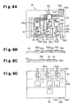
- FIG. 8A is a schematic plan view of the intermittent short circuit determining device of FIG. 7;
- FIG. 8B is a schematic front view of the intermittent short circuit determining device of FIG. 7;
- FIG. 8C is a schematic right side view of the intermittent short circuit determining device of FIG. 7;
- FIG. 8D is a schematic bottom view of the intermittent short circuit determining device of FIG. 7;
- FIG. 9 is a schematic right side view of the intermittent short circuit determining device of FIG. 7 in a moulded state
- FIG. 10A is a schematic perspective view illustrating a different embodiment of the intermittent short circuit determining device of FIG. 7;
- FIG. 10B is a schematic perspective view illustrating a different embodiment of the intermittent short circuit determining device of FIG. 7;
- FIG. 11A is a schematic perspective view illustrating a different embodiment of the intermittent short circuit determining device of FIG. 7;
- FIG. 11B is a schematic perspective view illustrating a different embodiment of the intermittent short circuit determining device of FIG. 7;
- FIG. 12 is a circuit diagram of an intermittent short circuit determining device according to a further embodiment of the present invention.
- FIG. 13 is a circuit diagram of an intermittent short circuit determining device according to a further embodiment of the present invention.
- FIG. 14 is a circuit diagram of an intermittent short circuit determining device according to a further embodiment of the present invention.
- FIG. 1 is a schematic circuit diagram of an intermittent short circuit determining device 80 according to a first embodiment of the present invention.
- FIG. 2 is a schematic perspective view of the intermittent short circuit determining device 80 .
- the intermittent short circuit determining device 80 is embodied in an automobile intermittent short circuit determining device.
- the intermittent short circuit determining device 80 is connected to a terminal block (not shown), which is included in an electric circuit of the automobile.
- the intermittent short circuit determining device 80 includes a conductive terminal 11 , a signal input terminal 31 , a current sensor (detecting means) 2 , a relay circuit (disconnecting means) 14 , an output terminal 32 , a determining circuit (determining means) 16 , and a relay electrode 18 .
- the relay circuit 14 includes a power MOSFET (hereinafter, simply referred to as FET).
- the intermittent short circuit determining device 80 includes a molded material such as a molded package 17 , which is made of epoxy resin.
- the intermittent short circuit determining device 80 is formed into a flat hexahedron.
- the conductive terminal 11 is flat and located on one side of the package 17 .
- An insulation (not shown), is formed on the inner surface of the conductive terminal 11 .
- the determining circuit 16 is located on the inner surface of the conductive terminal 11 .
- the insulation is not formed on the outer surface (bottom surface in FIG. 2) of the conductive terminal 11 .
- the conductive terminal 11 includes an L-shaped branching arm 11 a .
- the relay electrode 18 is located inside the branching arm 11 a , as shown in FIG. 2.
- the branching arm 11 a is connected to the relay electrode 18 by the current sensor (thin fuse) 2 .
- the currnt sensor 2 has a predetermined impedance Z.
- the current sensor 2 has a current capacity such that the current sensor 2 does not break when a current greater than or equal to a predetermined reference value (overcurrent) constantly flows for a predetermined reference time period.
- the output terminal 32 is bent in an L-shaped manner outside the package 17 as shown.
- the FET 14 is located on the flat surface of the output terminal 32 inside the package 17 .
- the drain of the FET 14 is connected to the relay electrode 18 by a conductive bar 19 .
- the source of the FET 14 is connected to the output terminal 32 .
- the gate of the FET 14 is connected to a relay circuit control terminal 20 of the determining circuit 16 (see FIG. 1).
- Input terminals 22 , 23 of the determining circuit 16 which is shown in FIG. 1, are connected to the conductive terminal 11 and the relay electrode 18 by lead wires 24 , 25 , respectively, as shown in FIG. 2.
- the conductive terminal 11 and the relay electrode 18 are connected to the ends of the current sensor 2 , respectively.
- the determining circuit 16 constantly receives the detection signal (voltage) through the conductive terminal 11 and the input terminals 22 , 23 .
- a ground terminal 27 is bent in an L-shaped manner outside the package 17 .
- the end of the ground terminal 27 inside the package 17 is connected to the determining circuit 16 by a lead wire 26 .
- the signal input terminal 31 is bent in an L-shaped manner outside the package 17 .
- the end of the signal input terminal 31 in the package 17 is connected to an external signal input terminal 28 of the determining circuit 16 .
- the signal input terminal 31 is connected to an external switch 30 of the automobile. When the external switch 30 is turned on, the signal input terminal 31 receives a switch ON signal (current control signal). When the external switch 30 is turned off, the signal input terminal 31 receives a switch OFF signal (current control signal).
- the determining circuit 16 includes an IC 16 A and a microcomputer 16 B.
- the determining circuit 16 determines whether an intermittent short circuit has occurred. That is, the IC 16 A receives the voltage on each terminal of the current sensor 2 (potential difference) through the input terminals 22 , 23 .
- the determining circuit 16 determines whether the received potential difference (load current) is greater than or equal to the predetermined threshold value by comparing the received voltages.
- the determining circuit 16 provides the result to the microcomputer 16 B.
- the microcomputer 16 B includes a CPU 6 , a ROM, and a RAM.
- the intermittent short circuit determining program and a close/open control program are stored in the ROM 7 .
- the operation memory is stored in the RAM 8 .
- the microcomputer 16 B determines whether an intermittent short circuit has occurred based on the intermittent short circuit determining program.
- the battery BT of the automobile is connected to a load circuit 29 via the current sensor 2 and a power MOSFET 14 , or relay circuit.
- the load circuit 29 includes, for example, a headlamp or a radio. Further, the load circuit 29 includes the electric wiring (electric lines) connected to the headlamp or the radio.
- FIG. 3 is a schematic circuit diagram of the IC 16 A of the determining circuit 16 .
- the IC 16 A includes a differential amplifier circuit 21 , a first comparator circuit 12 , a second comparator circuit 13 , resistors R 1 , R 2 , R 3 , and a charge pump 4 .
- the IC 16 A is connected to the microcomputer 16 B via input signal lines IS 1 , IS 2 and output signal lines OS 1 , OS 2 .
- a non-inverting input terminal (hereinafter, referred to as positive terminal) 21 a of the differential amplifier circuit (operation amplifier) 21 is connected to the input terminal 22 .
- a potential El at the battery side of the currnt sensor 2 is supplied to the positive terminal 21 a of the differential amplifier circuit 21 .
- An inverting input terminal (hereinafter, referred to as negative terminal) 21 b of the differential amplifier circuit 21 is connected to the input terminal 23 .
- a potential E 2 at the load side of the currnt sensor 2 is supplied to the negative terminal 21 b of the differential amplifier circuit 21 .
- the differential amplifier circuit 21 receives both potentials E 1 , E 2 from the currnt sensor 2 as detection signals, the potential difference (E 1 ⁇ E 2 ) is amplified by a predetermined factor.
- the amplified voltage Va is supplied from the output terminal 21 c to a negative terminal 12 a of the first comparator circuit (operation amplifier) 12 and to a negative terminal 13 a of the second comparator circuit (operation amplifier) 13 .
- the potential difference (E 1 ⁇ E 2 ) is produced between the two terminals of the currnt sensor 2 when the load current (detected current) IL that flows through the load circuit 29 and the currnt sensor 2 has a current value Id.
- the potential difference is described by “impedance Z ⁇ load current value Id”. Therefore, the amplified voltage Va is represented by the following equation.
- the amplified voltage Va is proportional to the current value Id, and the impedance Z is substantially constant.
- the current value Id represents the amplified voltage Va.
- the output terminal 21 c of the differential amplifier circuit 21 is connected to the negative terminal 12 a of the first comparator circuit 12 .
- a non-inverting input terminal, or a positive terminal 12 b , of the first comparator circuit 12 is connected to a median point between the resistors R 2 and R 3 .
- a first voltage threshold value VT 1 which is represented by the following equation, is applied to the positive terminal 12 b .
- the voltage value of the battery power source BT is represented by VB
- the resistance value of the resistor R 1 is represented by RA
- the resistance value of the resistor R 2 is represented by RB
- the resistance value of the resistor R 3 is represented by RC.
- VT 1 ( VB ⁇ RC /( RA+RB+RC ))
- An output terminal 12 c of the first comparator circuit 12 is connected to the microcomputer 16 B via the output signal line OS 1 .
- the first voltage threshold value VT 1 is set such that it is equal to the amplified voltage Va when the load current IL, which is equal to a first current threshold value A1, flows to the load circuit 29 .
- the first current threshold value A1 is within the current capacity range of the current supply lines.
- the first comparator circuit 12 compares the amplified voltage Va with the first voltage threshold value VT 1 . That is, the first comparator circuit 12 determines whether the current value Id is greater than the first current threshold value A1.
- the first comparator circuit 12 When the current value Id (amplified voltage Va) is less than or equal to the first current threshold value A1 (first voltage threshold value VT 1 ), the first comparator circuit 12 provides the microcomputer 16 B with a first comparison signal having a high level. When the load current value Id is greater than the first current threshold value A1, the first comparator circuit 12 provides the microcomputer 16 B with the first comparison signal at a low level.
- the output terminal 21 c of the differential amplifier circuit 21 is connected to the negative terminal 13 a of the second comparator circuit (operation amplifier) 13 .
- a positive terminal 13 b of the second comparator circuit 13 is connected to a median point between the resistors R 1 and R 2 . That is, a second voltage threshold value VT 2 , which is represented by the following equation, is applied to the positive terminal 13 b.
- VT 2 ( VB ⁇ ( RB+RC )/( RA+RB+RC ))
- An output terminal 13 c of the second comparator circuit 13 is connected to the microcomputer 16 B via the output signal line OS 2 .
- the second voltage threshold value VT 2 is set such that it is equal to the amplified voltage Va when the load current IL, which is equal to a second current threshold value A2, flows to the load circuit 29 .
- the second comparator circuit 13 After receiving the amplified voltage Va from the differential amplifier circuit 21 , the second comparator circuit 13 compares the amplified voltage Va with the second voltage threshold value VT 2 . The second comparator circuit 13 determines whether the load current value Id is greater than the second current threshold value A2. When the load current value Id (amplified voltage Va) is less than or equal to the second current threshold value A2 (second voltage threshold value VT 2 ), the second comparator circuit 13 provides the microcomputer 16 B with a second comparison signal having a high level. When the load current value Id is greater than the second current threshold value A2, the second comparator circuit 13 supplies the microcomputer 16 B with the second comparison signal at a low level. The microcomputer 16 B determines whether the load current value Id is greater than the reference value (A1, A2).
- the microcomputer 16 B determines whether an intermittent short circuit has occurred based on the following four characteristic values:
- Ratio DU of the sum of second time period TB to a predetermined time period ON-duty ratio, hereinafter, referred to as DUTY ratio
- An overcurrent number KS indicating the number of times that the load current IL exceeds a second current threshold value A2 during a predetermined time period.
- An output terminal of the IC 16 A is connected to the first output terminal 20 of the determining circuit 16 .
- the first output terminal 20 is connected to the gate of the FET 14 .
- the IC 16 A receives a current flow permission signal (first mode signal) from the microcomputer (processing circuit) 16 B, the IC 16 A charges a charge pump 4 and generates a FET ON signal that activates the FET 14 .
- the FET ON signal is sent to the gate of the FET 14 via the first output terminal 20 .
- the FET ON signal is sent to the gate, the portion between the drain and source of the FET 14 are connected. This supplies the load circuit 29 with the load current IL.
- the IC 16 A When the IC 16 A receives a current shutdown signal (second mode signal) from the microcomputer 16 B, the IC 16 A discharges the charge pump 4 and generates a FET OFF signal, which inactivates the FET 14 . When the FET OFF signal is provided to the gate, the drain and the source are disconnected. This stops the supply of the load current IL to the load circuit 29 .
- a current shutdown signal second mode signal
- Another output terminal (not shown) of the IC 16 A is connected to a light-emitting diode (hereinafter, referred to as LED) on the automobile.
- LED a light-emitting diode
- the IC 16 A receives a LED ON signal from the microcomputer 16 B, a LED goes on.
- the IC 16 A receives a LED OFF signal from the microcomputer 16 B, the LED goes off.
- the LED is, for example, installed in an instrument panel of the automobile (not shown).
- FIGS. 4, 5, and 6 are flowcharts illustrating the process of the intermittent short circuit determining program.
- the program is executed by the CPU 6 of the determining circuit 16 .
- the CPU 6 determines whether an intermittent short circuit has occurred in the electric circuit based on the intermittent short circuit determining program. When it is determined that an intermittent short circuit has not occurred, current is supplied to the load circuit 29 . When it is determined that an intermittent short circuit has occurred, the supply of current to the load circuit 29 is stopped.
- step S 1 When the microcomputer 16 B is supplied with a battery voltage VB from the battery power source BT, the CPU 6 resets counters CTA, CTB, C 3 , C 4 , C 5 , and C 6 to zero in step S 1 . Then, the CPU 6 proceeds to step S 2 .
- step S 2 the CPU 6 determines whether the switch ON signal has been provided. If it is determined that the switch ON signal has not been received, the CPU 6 proceeds to step S 16 . If it is determined that the switch ON signal has been received, the CPU 6 proceeds to step S 3 .
- step S 16 the CPU 6 supplies the IC 16 A with the current shutdown signal and the LED OFF signal.
- the IC 16 A receives the current shutdown signal, the IC 16 A generates the FET OFF signal.
- the IC 16 A inactivates the FET 14 based on the FET OFF signal.
- the IC 16 A receives the LED OFF signal, the IC 16 A turns off the LED accordingly.
- the CPU 6 then returns to step S 2 .
- step S 3 the CPU 6 provides the IC 16 A with the current flow permission signal. Upon receipt of the current flow permission signal, the IC 16 A generates the FET ON signal, which activates the FET 14 accordingly.
- step S 4 the CPU 6 receives the load current value Id and proceeds to step S 5 .
- step S 5 the CPU 6 determines whether the current value Id is greater than the first current threshold value A1 based on the first and the second comparison signals.
- the CPU 6 determines that the current value Id is less than or equal to the first current threshold value A1.
- the CPU 6 determines that the current value Id is greater than the first current threshold value A1.
- step S 6 If it is determined that the current value Id is greater than the first current threshold value A1, the CPU 6 proceeds to step S 6 . If it is determined that the current value Id is less than or equal to the first current threshold value A1, the CPU 6 proceeds to step S 17 .
- step S 17 the CPU 6 supplies the IC 16 A with the current flow permission signal and the LED OFF signal.
- the IC 16 A Upon receipt of the current flow permission signal, the IC 16 A generates the FET ON signal, which activates the FET 14 accordingly. This allows the current to be supplied to the load circuit 29 .
- the IC 16 A Upon receipt of the LED OFF signal, the IC 16 A turns off the LED.
- the microcomputer 16 B then returns to step S 2 .
- step S 6 the CPU 6 increments the counter CTA by a value of one and proceeds to step S 7 .
- the counter CTA calculates the first time period TA during which the continuous load current IL exceeds the first current threshold value A1.
- step S 7 the CPU 6 determines whether the current value Id is greater than the second current threshold value A2 according to the first and the second comparison signals.
- the CPU 6 determines that the current value Id is greater than the second current threshold value A2 and proceeds to step S 8 .
- the CPU 6 determines that the current value Id is less than or equal to the second current threshold value A2 and proceeds to step S 8 .
- step S 8 If it is determined that the current value Id is greater than the second current threshold value A2, the CPU 6 proceeds to step S 8 . If it is determined that the current value Id is less than or equal to the second current threshold value A2, the CPU 6 proceeds to step S 18 .
- step S 18 the CPU 6 determines whether the first time period TA is greater than the first reference time period T 1 . If it is determined that the first time period TA is greater than the first reference time period T 1 , the CPU 6 determines that the dead short may occur and proceeds to step S 19 . If it is determined that the first time period TA is less than or equal to the first reference time period T 1 , the CPU 6 proceeds to step S 17 .
- step S 19 CPU 6 supplies the IC 16 A with the current shutdown signal and the LED ON signal.
- the IC 16 A Upon receipt of the current shutdown signal, the IC 16 A generates the FET OFF signal, which inactivates the FET 14 accordingly.
- the current supply to the load circuit 29 is stopped. This prevents the dead short circuit from occurring and protects the load circuit 29 against the overcurrent caused by the dead short circuit.
- the IC 16 A turns on the LED. The CPU 6 proceeds to step S 20 .
- step S 20 the CPU 6 send a DIAG signal and executes a self-diagnostic test.
- the CPU 6 then proceeds to step S 21 .
- step S 21 the CPU 6 determines whether an ignition signal of the automobile has been received. If it is determined that the ignition signal has not been received, the CPU 6 proceeds to step S 19 . If it is determined that the ignition signal is received, the CPU 6 proceeds to step S 1 .
- step S 7 of FIG. 4 If it is determined in step S 7 of FIG. 4 that the load current value Id is greater than the second current threshold value A2, the CPU 6 increments the count value of the counter CTB in step S 8 .
- the counter CTB calculates a second time period TB during which the continuous current IL exceeds the second current threshold value A2. The CPU 6 then proceeds to step S 9 .
- step S 9 the CPU 6 increments the count value of an ON time period counter C 3 and proceeds to step S 10 .
- the ON time period counter C 3 adds up the ON time of the load current IL.
- step S 10 the CPU 6 increments each count value of an overcurrent counter C 5 and a time period counter C 6 , and proceeds to step S 11 .
- the overcurrent counter C 5 calculates the overcurrent number, by which the load current IL exceeds the second current threshold value A2.
- step S 11 the CPU 6 determines whether the second time period TB is greater than a second reference time period T 2 (T 2 ⁇ T 1 ). If it is determined that the second time period TB is greater than the second reference time period T 2 , the CPU 6 determines that an intermittent short circuit has occurred and proceeds to step S 19 . In step S 19 , the CPU 6 provides the IC 16 A with the current shutdown signal and inactivates the FET 14 .
- step S 11 if it is determined that the second time period TB is less than or equal to the second reference time period T 2 , the CPU 6 proceeds to step S 12 .
- step S 12 the microcomputer 16 B calculates the ratio DU (duty ratio) of the ON time period of the load current IL to the predetermined time period. The microcomputer 16 B calculates the ratio DU based on the value of the ON time period counter C 3 .
- step S 13 CPU 6 determines whether the duty ratio DU is greater than a reference duty ratio D1. If it is determined that the duty ratio DU is greater than the reference duty ratio D1, the CPU 6 determines that an intermittent short circuit has occurred and proceeds to step S 19 . In step S 19 , the CPU 6 provides the IC 16 A with the current shutdown signal and inactivates the FET 14 . This protects the load circuit 29 . If it is determined that the duty ratio DU is less than or equal to the reference duty ratio D1, the CPU 6 proceeds to step S 14 .
- step S 14 the CPU 6 calculates the overcurrent number KS, which is the number of times the load current IL exceeds the second current threshold value A2 during the predetermined time period.
- the CPU 6 calculates the overcurrent number KS based on the value of the overcurrent counter C 5 and the value of the time period counter C 6 .
- step S 15 the CPU 6 determines whether the overcurrent number KS is greater than the reference overcurrent number K1. If it is determined that the overcurrent number KS is greater than a reference overcurrent number K1, the CPU 6 determines that an intermittent short circuit has occurred and proceeds to step S 19 . In step S 19 , the CPU 6 supplies the IC 16 A with the current shutdown signal and inactivates the FET 14 . This protects the load circuit 29 . If it is determined that the overcurrent number KS is less than or equal to the reference overcurrent number K1, the CPU 6 proceeds to step S 17 .
- the first and second reference time periods T 1 , T 2 , the reference duty ratio D1, and the reference overcurrent number K1 are stored in the ROM 7 .
- the microcomputer 16 B receives the switch ON signal when the external switch 30 is switched on.
- the microcomputer 16 B closes the FET 14 based on the close/open control program.
- the microcomputer 16 B provides the signal to the gate of the FET 14 via the relay circuit control terminal 20 of the IC 16 A to activate the FET 14 .
- the microcomputer 16 B receives the switch OFF signal when the external switch 30 is turned off.
- the microcomputer 16 B opens the FET 14 based on the close/open control program.
- the microcomputer 16 B provides the signal to the gate of the FET 14 via the relay circuit control terminal 20 of the IC 16 A to inactivate the FET 14 .
- the intermittent short circuit determining device 80 provides the following advantages.
- the CPU 6 inactivates the FET 14 and stops the supply of current to the load circuit 29 when it is determined that the following conditions are met.
- the load current value Id is greater than the first current threshold value A1 and is less than or equal to the second current threshold value A2.
- the first time period TA is greater than the first reference time period T 1 . This prevents a dead short circuit from occurring and protects the load circuit 29 of the automobile.
- the CPU 6 determines that a dead short circuit has occurred when the following conditions are met.
- the load current value Id is greater than the second current threshold value A2.
- the second time period TB is greater than the second reference time period T 2 . Then, the CPU 6 inactivates the FET 14 and stops the supply of current to the load circuit 29 . This protects the electric lines from overcurrent caused by a dead short circuit.
- the CPU 6 determines that an intermittent short circuit has occurred when the following conditions are met.
- the load current value Id is greater than the second current threshold value A2.
- the second time period TB is less than or equal to the second reference time period T 2 .
- the duty ratio DU of the detected current IL is greater than the reference duty ratio D1. Then, the CPU 6 inactivates the FET 14 and stops the supply of current to the load circuit 29 . This protects the electric lines from overcurrent caused by an intermittent short circuit.
- the CPU 6 determines that an intermittent short circuit has occurred when the following conditions are met: the load current value Id is greater than the second current threshold value A2; the second time period TB is less than or equal to the second reference time period T 2 ; the duty ratio DU is less than or equal to the reference value D1; and the overcurrent number KS is greater than the reference overcurrent number K1. Then, the CPU 6 inactivates the FET 14 and stops the supply of current to the load circuit 29 . This protects the electric lines from overcurrent caused by the intermittent short circuit.
- the current sensor 2 functions as a fuse. Therefore, even if the determining circuit 16 or the FET 14 fails to function because of, for example, the occurrence of a dead short circuit in the load circuit 29 , the current sensor 2 breaks as a fuse and stops the supply of current to the load circuit 29 .
- the determining circuit 16 of the intermittent short circuit determining device 80 is connected to the external switch 30 (external switch circuit).
- the external switch 30 determines whether or not to supply the load current IL to the load circuit 29 .
- the determining circuit 16 activates the FET 14 .
- the determining circuit 16 inactivates the FET 14 . Therefore, the current supply to the load circuit 29 is controlled by the operation of the external switch 30 .
- the intermittent short circuit determining device 80 includes the currnt sensor 2 , the FET 14 , and the determining circuit 16 , which are integrated in the molded package 17 .
- the size of the intermittent short circuit determining device 80 is reduced and it is inexpensive.
- the relay circuit includes the FET 14 .
- the configuration of the relay circuit is simplified and the size of the intermittent short circuit determining device 80 is reduced.
- the size reduction is also advantageous for packaging the device 80 .
- step S 5 of FIG. 4 if it is determined that the load current value Id is greater than the first current threshold value A1, the CPU 6 may proceed to step S 18 .
- step S 18 if it is determined that the first time period TA is less than or equal to the first reference time period T 1 , the CPU 6 may proceed to step S 7 .
- step S 5 of FIG. 4 if it is determined that the load current value Id is greater than the first current threshold value A1, the CPU 6 may proceed to step S 19 .
- the steps S 6 , S 7 , S 8 , S 9 , S 10 , S 11 , S 12 , S 13 , S 14 , S 15 , and S 18 are omitted.
- the IC 16 A may have only one comparator circuit.
- the IC 16 A may also have more than three comparator circuits.
- the first mode signal and the second mode signal may be formed of only the current flow permission signal and the current shutdown signal, respectively.
- the current threshold value, the reference duty ratio, and the reference overcurrent number K1 are set as required. That is, different current threshold values may be set as the load current Id. Load current ranges are defined by the current threshold values. At least one of the reference ON duty ratio and the reference overcurrent number K1 may be set in correspondence with each load current range. In this case, the intermittent short circuit determining program is executed for each load current range.
- the following tables 1, 2 and 3 show the examples of combinations of conditions for the CPU 6 to determine that an intermittent short circuit has occurred.
- the occurrence of an intermittent short circuit may be determined based on the combinations listed in the tables 1 to 3.
- Each combination of circles in a column indicates abnormal conditions.
- Table 1 shows load current ranges defined by the current threshold values A1, A2, A3, A4, A5 (A1 ⁇ A2 ⁇ A3 ⁇ A4 ⁇ A5) and duty ratio areas defined by the duty ratios D1, D2, D3, D4, D5 (D1 ⁇ D2 ⁇ D3 ⁇ D4 ⁇ D5).
- the row marked “A1 ⁇ ” indicates that A1 ⁇ load current ⁇ A2.
- the circles in the lowest row of the current value and in the lowest row of the duty ratio indicate that each of the detected value is greater than or equal to the indicated value of the associated row.
- the circle in the row marked “A5 ⁇ ” represents that the detected value is greater than or equal to A5.
- “D1 ⁇ duty ratio ⁇ D2” corresponds to “A1 ⁇ load current ⁇ A2”.
- Table 2 shows the load current ranges defined by the current values A1 to A5 and over current number ranges defined by the numbers K1, K2, K3, K4, K5 (K1 ⁇ K2 ⁇ K3 ⁇ K4 ⁇ K5). “K1 ⁇ overcurrent number ⁇ K2” corresponds to “A1 ⁇ load current ⁇ A2”. For, example when A1 ⁇ load current ⁇ A2 and K1 ⁇ overcurrent number ⁇ K2, it is determined that an intermittent short circuit has occurred. TABLE 2 Intermittent short Circuit Comb. 6 Comb. 7 Comb. 8 Comb. 9 Comb.
- Table 3 shows the load current ranges defined by the current values A1 to A5, the duty ratio ranges defined by the duty ratios D6, D7, D8, D9, D10 (D5 ⁇ D6 ⁇ D7 ⁇ D8 ⁇ D9 ⁇ D10), and the overcurrent number ranges defined by the overcurrent number K6, K7, K8, K9, K10 (K5 ⁇ K6 ⁇ K7 ⁇ K8 ⁇ K9 ⁇ K10).
- “D6 ⁇ duty ratio ⁇ D7” and “K6 ⁇ overcurrent number ⁇ K7” correspond to “A1 ⁇ load current A2”.
- the combination is A1 ⁇ load current ⁇ A2 and D6 ⁇ duty ratio ⁇ D7 or K1 ⁇ overcurrent number ⁇ K2, it is determined that an intermittent short circuit has occurred.
- Tables 1 to 3 are stored in the ROM 7 as maps.
- the CPU 6 refers to the reference value of each load current range when determining the occurrence of the intermittent short circuit.
- FIG. 7 is a schematic circuit diagram of an intermittent short circuit determining device 90 according to a second embodiment of the present invention.
- the intermittent short circuit determining device 90 is embodied in an automobile intermittent short circuit determining device.
- FIG. 8A is a plan view of the intermittent short circuit determining device 90 without molded material.
- FIG. 8B is a front view of the determining device 90 .
- FIG. 8C is a right side view of the determining device 90 .
- FIG. 9 is a right side view of the intermittent short circuit determining device 90 .
- a rectangular multi-layer insulating substrate 41 has a wide conductive pattern (hereinafter, referred to as the conductive terminal pattern) 42 a .
- the conductive terminal pattern 42 a has three branching conductors 43 .
- the branching conductors 43 are connected to lands 44 (see FIG. 8A) through plated through holes (not shown), respectively.
- the lands 44 and the plated through holes are located on the multi-layer insulating substrate 41 (upper surface in FIG. 8B).
- each thin first, second, and third current sensor 45 a , 45 b , and 45 c is connected to one of the lands 44 .
- Each first, second, and third current sensor 45 a , 45 b , and 45 c transverses one of the recesses 46 on the multi-layer insulating substrate 41 .
- Another end of each first, second, and third current sensor 45 a , 45 b , and 45 c is connected to one of the other lands 47 located on the multi-layer insulating substrate 41 .
- the lands 47 are connected to the drains (not shown) of the first, second and third FET (relay circuit) 49 a , 49 b , and 49 c by the connecting leads 48 , respectively.
- the current capacity of each connecting lead 48 is greater than that of the corresponding first, second, and third current sensor 45 a , 45 b , and 45 c.
- the first, second, and third FETs 49 a , 49 b , 49 c are each fixed to one end of each first, second, and third conductive terminal 50 a , 50 b , and 50 c via the associated sources (not shown).
- the conductive terminals 50 a , 50 b , and 50 c are located on the multi-layer insulating substrate 41 .
- the other end of each of the first, second, and third conductive terminals 5 0 a , 50 b , 50 c projects outward from the multi-layer insulating substrate 41 .
- the determining circuit 51 is fixed to a GND connecting terminal 55 formed on the multi-layer insulating substrate 41 .
- the internal circuit of the determining circuit 51 is grounded via the GND connecting terminal 55 .
- One end of the GND connecting terminal 55 projects outward from the multi-layer insulating substrate 41 .
- Each land 44 is connected to one end of each first, second, and third current sensor detect terminals (not shown) of the determining circuit 51 via plated through holes (not shown), wiring patterns located on the internal layer of the multi-layer insulating substrate 41 , and lead wires.
- Each land 47 is connected to the other end of each first, second, and third current sensor detect terminals (not shown) of the determining circuit 51 via the plated through holes (not shown), wiring patterns located on the internal layer of the multi-layer insulating substrate 41 , and lead wires.
- the first, second, and third output terminal of the determining circuit 51 is connected to the gates (not shown) of the first, second, and third FET 49 a , 49 b , 49 c via lead wires and wiring patterns located on the multi-layer insulating substrate 41 , respectively.
- Three external signal input terminals of the determining circuit 51 are connected to the first, second, and third signal input terminals 52 a , 52 b , 52 c on the multi-layer insulating substrate 41 via lead wires, respectively.
- the other end of each first, second, and third signal input terminal 52 a , 52 b , 52 c projects outward from the multi-layer insulating substrate 41 .
- the first, second, and third signal input terminals 52 a , 52 b , and 52 c are connected to the first, second, and third automobile external switches 30 a , 30 b , and 30 c (see FIG. 7), respectively.
- the automobile external switches function as the external switch circuit of the automobile.
- a switch ON signal is provided to the determining circuit 51 .
- a switch OFF signal is provided to the determining circuit 51 .
- each member arranged on the multi-layer insulating substrate 41 is packaged with, for example, the molded material, which is made of epoxy resin.
- the intermittent short circuit determining device 90 is formed into a flat hexahedron.
- the first, second, and third conductive terminals 50 a , 50 b , 50 c , the first, second, and third signal input terminals 52 a , 52 b , 52 c , and one end of the GND connecting terminal 55 project outward from the package.
- the determining circuit 51 includes an IC and a microcomputer as in the determining circuit 16 of the second embodiment.
- the determining circuit 51 determines the occurrence of an intermittent short circuit with respect to the first, second, and third current sensors 45 a , 45 b , and 45 c .
- the determining circuit 51 selectively closes and opens each FET 49 a , 49 b , and 49 c based on the switch ON/OFF signal of the corresponding first, second, and third external switch 30 a , 30 b , and 30 c .
- the intermittent short circuit determining method and the close/open control of FET 49 a , 49 b , 49 c are equivalent to those of the first embodiment.
- the intermittent short circuit determining device 90 is arranged on the terminal block (not shown), which is provided in the electric circuit of automobiles.
- the first, second, or third current sensor 45 a , 45 b , 45 c breaks and stops the supply of current if the determining circuit 51 of the intermittent short circuit determining device 90 or one of the FET 49 a , 49 b , 49 c fails to operate properly. The failure may occur due to the occurrence of a dead short circuit in one of the load circuits 54 a , 54 b , 54 c .
- a dead short circuit causes a large amount of current to continuously flow in an electric circuit.
- the load circuits 54 a , 54 b , 54 c include, for example, a lamp (headlamp, fog lamp), a radio, or car audio equipment.
- the intermittent short circuit determining device 90 of the second embodiment provides the following advantages.
- the first, second, and third current sensors 45 a , 45 b , 45 c , and the first, second, and third FET (relay circuit) 49 a , 49 b , 49 c are provided in correspondence with the load circuits 54 a , 54 b , 54 c .
- the determining circuit 51 determines whether each external switch 30 a , 30 b , 30 c (external switch circuit) is switched on or switched off.
- the external switches 30 a , 30 b , 30 c are used to select whether to supply or stop supplying the current to the load circuits 54 a , 54 b , 54 c , respectively.
- the determining circuit 51 selectively activates and inactivates the corresponding first, second, and third FET 49 a , 49 b , 49 c , according to the determination.
- the determining circuit 51 determines whether an intermittent short circuit has occurred in each load circuit 294 a , 54 b , 54 c separately. Thus, the determining circuit 51 stops the current supply to only the load circuit, in which the intermittent short circuit occurs. The flow of current to the load circuits 54 a , 54 b , 54 c is permitted or stopped in accordance with the operation of the external switches 30 a , 30 b , 30 c , respectively.
- FIGS. 10A, 10B, 11 A, 11 B illustrate other embodiments of the intermittent short circuit determining device 90 of the second embodiment.
- Each intermittent short circuit determining device 90 A, 90 B, 90 C, 90 D has substantially the same circuit as in FIG. 7.
- the conductive terminal 11 is provided in FIGS. 10A, 10B, 11 A, 11 B instead of the conductive terminal pattern 42 a.
- the intermittent short circuit determining device 90 A in FIG. 10A is connected to a circuit substrate in an electric connection box.
- the first, second, and third conductive terminals 50 a , 50 b , 50 c , the first, second, and third signal input terminals 52 a , 52 b , 52 c , and GND connecting terminal 55 are bent in an L-shaped manner and project from the same side of a molded package 53 .
- the first, second, and third conductive terminals 50 a , 50 b , 50 c , the first, second, and third signal input terminals 52 a , 52 b , 52 c , and the GND connecting terminal 55 are bent vertically (downward in FIG. 11A) and project from the same side of the molded package 53 .
- the first, second, and third conductive terminals 50 a , 50 b , 50 c , the first, second, and third signal input terminals 52 a , 52 b , 52 c , the GND connecting terminal 55 , and the conductive terminal 11 project straightly from the same side of the molded package 53 .
- the configuration of the electric circuit differs from that of the intermittent short circuit determining device 90 of the second embodiment.
- the differences from the electric circuit of the second embodiment will mainly be discussed below.
- the intermittent short circuit determining device 90 E of FIG. 12 includes a single FET (relay circuit or disconnecting means) 49 , which is connected to the battery BT.
- Three branching circuits, which are connected to the FET 49 are connected to the first, second, and third current sensors 45 a , 45 b , 45 c , respectively.
- the first, second, and third current sensors 45 a , 45 b , 45 c are provided with the determining circuits 51 a , 51 b , 51 c , respectively.
- Each determining circuit 51 a , 51 b , 51 c receives the switch ON signal or the switch OFF signal from the corresponding external switch 30 a , 30 b , 30 c .
- the external switches 30 a , 30 b , 30 c are used to selectively close and open the circuit including the load circuits 54 a , 54 b , 54 c .
- Each determining circuit 51 a , 51 b , 51 c selectively activates and deactivates the FET 49 according to the switch ON/OFF signal.
- Each determining circuit 51 a , 51 b , 51 c determines whether an intermittent short circuit has occurred according to the detected voltage (load current) assorts the two terminals of the corresponding current sensor 45 a , 45 b , 45 c . When it is determined that an intermittent short circuit has occurred, the associated determining circuit 51 a , 51 b , 51 c inactivates the FET 49 .
- the intermittent short circuit determining device 90 E is integrated in the molded package as in the second embodiment.
- the load circuits 54 a , 54 b , and 54 c are selectively opened and closed by the single FET 49 .
- the intermittent short circuit determining device 90 F in FIG. 13 includes the circuit configuration, which is equivalent to that of the intermittent short circuit determining device 90 of the second embodiment.
- the determining device 90 F includes separate determining circuits 51 a , 51 b , 51 c for detecting the voltage on two terminals of each first, second, and third current sensor 45 a , 45 b , 45 c.
- Each determining circuit 51 a , 51 b , 51 c receives the switch ON signal or the switch OFF signal from the corresponding external switches 30 a , 30 b , 30 c .
- the external switches 30 a , 30 b , 30 c are used to selectively close and open the load circuits 54 a , 54 b , 54 c based on the switch ON/OFF signals.
- Each determining circuit 51 a , 51 b , 51 c selectively activates and inactivates the FET 49 a , 49 b , 49 c separately according to the switch ON/OFF signal.
- Each determining circuit 51 a , 51 b , 51 c determines whether an intermittent short circuit has occurred according to the detected voltage (load current) on two terminals of the corresponding first, second, and third current sensor 45 a , 45 b , 45 c . When it is determined that an intermittent short circuit has occurred, each determining circuit 51 a , 51 b , 51 c inactivates the FET 49 a , 49 b , 49 c separately.
- the intermittent short circuit determining device 90 F is integrated in the molded package as in the second embodiment.
- the circuit of the intermittent short circuit determining device 90 G of FIG. 14 includes three circuits of the intermittent short circuit determining device 90 , which are parallel.
- the intermittent short circuit determining device 90 G independently determines the occurrence of the intermittent short circuit in each load circuit 294 a , 54 b , 54 c and performs the close/open control of the load current.
- One of external batteries Ba, Bb, Bc is connected to each independent circuit in the intermittent short circuit determining device 90 G.
- the current sensor 2 may be an element or circuit that generates a detection signal that is proportional to the load current.
- a sensor that uses a shunt resistor, a thermistor, or a Hall element may be used.
- the determining circuits 16 may be set such that the circuits 16 determine that an intermittent short circuit has occurred in detected current IL if the resistance loss in the current sensor 2 is greater than the predetermined resistance loss.
- the determining circuit 16 may also be set such that the circuits 16 determine that an intermittent short circuit has occurred in the load current if the temperature increase caused by the resistance loss in current sensor 2 is greater than the predetermined value.
- the determining circuits 16 may be predetermined logic circuits.
- the relay circuit may be any circuit, which stops the load current according to the control signal.
- the relay circuit may be a relay using a semiconductor, or an electromagnetic relay.
- the intermittent short circuit determining device of the present invention may be embodied in other than the automobile intermittent short circuit determining device.
Landscapes
- Emergency Protection Circuit Devices (AREA)
Abstract
Description
- The present invention relates to a device and method for determining the occurrence of an intermittent short circuit. More particularly, the present invention relates to an intermittent short circuit determining device and an intermittent short circuit determining method that detects overcurrent flowing through an electric circuit of an automobile.
- U.S. Pat. No. 4,023,264 describes a blade fuse installed in a fuse box of an automobile. Blade fuses, which are often used in electric circuits of automobiles, have a slow-burn characteristic. Due to the slow-burn characteristic, blade fuses are not melted by momentary excess currents but are melted by continuous excess currents that flow for a certain period of time.
- Blade fuses normally melt and break when a dead short circuit occurs but do not break when an intermittent short circuit occurs. A dead short circuit causes a large amount of current to continuously flow in an electric circuit. An intermittent short circuit causes current to flow intermittently and within a short period of time in an electric circuit. An intermittent short circuit is a short circuit, which occurs when, for example, vibrations cause the electric wiring of an automobile to contact the body of the automobile. When an intermittent short circuit current continuously flows through the electric circuit of the automobile, for example, the electric circuit may be over-supplied with current. Thus, there is a need for an intermittent short circuit determining device that accurately detects the occurrence of an intermittent short circuit.
- One of the inventors of the present invention disclosed intermittent short circuit determining devices in Japanese Unexamined Patent Publication Nos. 11-273544 (Japanese Patent Application No. 10-90866) and 2000-90808 (Japanese Patent Application No. 10-255204). The disclosed intermittent short circuit determining devices accurately detect the occurrence of intermittent short circuits. However, the prior art intermittent short circuit determining devices include separate parts for determining the occurrence of an intermittent short circuit and for disconnecting the electric circuit. This makes the prior art intermittent short circuit determining devices large and expensive.
- It is an object of the present invention to provide a device and method for detecting the occurrence of an intermittent short circuit more accurately.
- A further object of the present invention is to provide a compact and inexpensive intermittent short circuit determining device.
- To achieve the above object, the present invention provides an intermittent short circuit determining device located between a power source and a load circuit in a vehicle electric circuit. The intermittent short circuit determining device includes detecting means for detecting current flowing through the load circuit, determining means for determining whether the current detected by the detecting means is an intermittent short circuit, and disconnecting means for disconnecting the load circuit when the determining means judges that there is an abnormality. The determining means is selectively connected to an external switch circuit, which selectively supplies and stops current to the load circuit. The determining means determines whether the external switch circuit is switched on or off, and switches the disconnecting means on or off according to the determination.
- The present invention also provides an intermittent short circuit determining device for determining whether an intermittent short circuit has occurred in a load circuit. The rare short circuit determining device includes detecting means, determining means and disconnecting means. The detecting means is for detecting a load current, which flows through the load circuit, and for generating a detection signal. The determining means is connected to the sensor. The determining means determines whether an intermittent short circuit has occurred based on the detection signal. The disconnecting means is connected to the determining means. The disconnecting means stops the supply of the load current to the load circuit when it is determined that an intermittent short circuit has occurred. The determining means determines whether an intermittent short circuit has occurred based on at least one of four characteristic values. The characteristic values include the value of a load current flowing through the load circuit, a time period during which the load current exceeds a current threshold value, an ON-duty ratio indicating the ratio of a time period when the load current exceeds the current threshold value relative to a predetermined time period, and an actual overcurrent number indicating the number of times that the load current exceeds the current threshold value during a predetermined time period. The determining circuit switches the disconnecting means off according to the determination.
- The present invention also provides a method for determining the occurrence of an intermittent short circuit in a load circuit. The method includes at least one of four comparing steps including a current comparison step, a time period comparison step, a duty ratio comparison step, and an overcurrent number comparison step. The current comparison step compares the value of a load current flowing through the load circuit with a current threshold value. The time period comparing step compares a time period during which the load current exceeds the current threshold value with a reference time period. The duty ratio comparison step compares an ON-duty ratio with a reference ON-duty ratio. The ON-duty ratio indicates the ratio of a time period during which the load current exceeds the current threshold value relative to a predetermined time period. The overcurrent number comparison step compares an actual overcurrent number indicating the number of times that the load current exceeds the current threshold value during the predetermined time period with a reference overcurrent number.
- A further aspect of the present invention is a method for determining whether an intermittent short circuit has occurred in a load circuit. The method includes comparing the value of a load current that flows in the load circuit with a first current threshold value, comparing the load current value with a second current threshold value, the second current threshold value being greater than the first current threshold value, comparing a first time period, during which the load current exceeds the first current threshold value, with a first reference time period, comparing a second time period, during which the load current exceeds the second current threshold value, with a second reference time period, comparing an ON-duty ratio with a reference ON-duty ratio, wherein the ON-duty ratio is the ratio of a time period when the load current exceeds the second current threshold value relative to a predetermined time period, and comparing an overcurrent number with a reference overcurrent number, wherein the overcurrent number is the number of times that the load current exceeds the second current threshold value during a predetermined time period.
- Other aspects and advantages of the present invention will become apparent from the following description, taken in conjunction with the accompanying drawings, illustrating by way of example the principles of the invention.
- The invention, together with objects and advantages thereof, may best be understood by reference to the following description of the presently preferred embodiments together with the accompanying drawings in which:
- FIG. 1 is a schematic circuit diagram of an intermittent short circuit determining device according to a first embodiment of the present invention;
- FIG. 2 is a schematic perspective view of the intermittent short circuit determining device of FIG. 1;
- FIG. 3 is a schematic circuit diagram of an IC in the intermittent short circuit determining device of FIG. 1;
- FIG. 4 is a flowchart illustrating an intermittent short circuit determining control program executed by a determining circuit of the intermittent short circuit determining device of FIG. 1;
- FIG. 5 is a flowchart illustrating an intermittent short circuit determining control program executed by a determining circuit of the intermittent short circuit determining device of FIG. 1;
- FIG. 6 is a flowchart illustrating an intermittent short circuit determining control program executed by a determining circuit of the intermittent short circuit determining device of FIG. 1;
- FIG. 7 is a schematic circuit diagram of an intermittent short circuit determining device according to a second embodiment of the present invention;
- FIG. 8A is a schematic plan view of the intermittent short circuit determining device of FIG. 7;
- FIG. 8B is a schematic front view of the intermittent short circuit determining device of FIG. 7;
- FIG. 8C is a schematic right side view of the intermittent short circuit determining device of FIG. 7;
- FIG. 8D is a schematic bottom view of the intermittent short circuit determining device of FIG. 7;
- FIG. 9 is a schematic right side view of the intermittent short circuit determining device of FIG. 7 in a moulded state;
- FIG. 10A is a schematic perspective view illustrating a different embodiment of the intermittent short circuit determining device of FIG. 7;
- FIG. 10B is a schematic perspective view illustrating a different embodiment of the intermittent short circuit determining device of FIG. 7;
- FIG. 11A is a schematic perspective view illustrating a different embodiment of the intermittent short circuit determining device of FIG. 7;
- FIG. 11B is a schematic perspective view illustrating a different embodiment of the intermittent short circuit determining device of FIG. 7;
- FIG. 12 is a circuit diagram of an intermittent short circuit determining device according to a further embodiment of the present invention;
- FIG. 13 is a circuit diagram of an intermittent short circuit determining device according to a further embodiment of the present invention; and
- FIG. 14 is a circuit diagram of an intermittent short circuit determining device according to a further embodiment of the present invention.
- In the drawings, like numerals are used for like elements throughout.
- (First Embodiment)
- FIG. 1 is a schematic circuit diagram of an intermittent short
circuit determining device 80 according to a first embodiment of the present invention. FIG. 2 is a schematic perspective view of the intermittent shortcircuit determining device 80. The intermittent shortcircuit determining device 80 is embodied in an automobile intermittent short circuit determining device. The intermittent shortcircuit determining device 80 is connected to a terminal block (not shown), which is included in an electric circuit of the automobile. - As shown in FIG. 2, the intermittent short
circuit determining device 80 includes aconductive terminal 11, asignal input terminal 31, a current sensor (detecting means) 2, a relay circuit (disconnecting means) 14, anoutput terminal 32, a determining circuit (determining means) 16, and arelay electrode 18. Therelay circuit 14 includes a power MOSFET (hereinafter, simply referred to as FET). - The intermittent short
circuit determining device 80 includes a molded material such as a moldedpackage 17, which is made of epoxy resin. The intermittent shortcircuit determining device 80 is formed into a flat hexahedron. Theconductive terminal 11 is flat and located on one side of thepackage 17. An insulation (not shown), is formed on the inner surface of theconductive terminal 11. The determiningcircuit 16 is located on the inner surface of theconductive terminal 11. The insulation is not formed on the outer surface (bottom surface in FIG. 2) of theconductive terminal 11. - The
conductive terminal 11 includes an L-shaped branchingarm 11 a. Therelay electrode 18 is located inside the branchingarm 11 a, as shown in FIG. 2. The branchingarm 11 a is connected to therelay electrode 18 by the current sensor (thin fuse) 2. Thecurrnt sensor 2 has a predetermined impedance Z. Thecurrent sensor 2 has a current capacity such that thecurrent sensor 2 does not break when a current greater than or equal to a predetermined reference value (overcurrent) constantly flows for a predetermined reference time period. - The
output terminal 32 is bent in an L-shaped manner outside thepackage 17 as shown. TheFET 14 is located on the flat surface of theoutput terminal 32 inside thepackage 17. The drain of theFET 14 is connected to therelay electrode 18 by a conductive bar 19. The source of theFET 14 is connected to theoutput terminal 32. The gate of theFET 14 is connected to a relaycircuit control terminal 20 of the determining circuit 16 (see FIG. 1). -
Input terminals circuit 16, which is shown in FIG. 1, are connected to theconductive terminal 11 and therelay electrode 18 bylead wires conductive terminal 11 and therelay electrode 18 are connected to the ends of thecurrent sensor 2, respectively. The determiningcircuit 16 constantly receives the detection signal (voltage) through theconductive terminal 11 and theinput terminals - A
ground terminal 27 is bent in an L-shaped manner outside thepackage 17. The end of theground terminal 27 inside thepackage 17 is connected to the determiningcircuit 16 by alead wire 26. - If one of the determining
circuit 16 and theFET 14 in the intermittent shortcircuit determining device 80 does not function properly and a dead short circuit occurs, thecurrent sensor 2, which functions as a fuse, breaks and the current supply to aload circuit 29 is stopped. - As shown in FIG. 2, the
signal input terminal 31 is bent in an L-shaped manner outside thepackage 17. The end of thesignal input terminal 31 in thepackage 17 is connected to an externalsignal input terminal 28 of the determiningcircuit 16. - The
signal input terminal 31 is connected to anexternal switch 30 of the automobile. When theexternal switch 30 is turned on, thesignal input terminal 31 receives a switch ON signal (current control signal). When theexternal switch 30 is turned off, thesignal input terminal 31 receives a switch OFF signal (current control signal). - The determining
circuit 16 includes anIC 16A and amicrocomputer 16B. The determiningcircuit 16 determines whether an intermittent short circuit has occurred. That is, theIC 16A receives the voltage on each terminal of the current sensor 2 (potential difference) through theinput terminals circuit 16 determines whether the received potential difference (load current) is greater than or equal to the predetermined threshold value by comparing the received voltages. The determiningcircuit 16 provides the result to themicrocomputer 16B. - The
microcomputer 16B includes aCPU 6, a ROM, and a RAM. The intermittent short circuit determining program and a close/open control program are stored in theROM 7. The operation memory is stored in theRAM 8. Themicrocomputer 16B determines whether an intermittent short circuit has occurred based on the intermittent short circuit determining program. - The battery BT of the automobile is connected to a
load circuit 29 via thecurrent sensor 2 and apower MOSFET 14, or relay circuit. Theload circuit 29 includes, for example, a headlamp or a radio. Further, theload circuit 29 includes the electric wiring (electric lines) connected to the headlamp or the radio. - The determining
circuit 16 of the intermittent shortcircuit determining device 80 will now be discussed. FIG. 3 is a schematic circuit diagram of theIC 16A of the determiningcircuit 16. - The
IC 16A includes adifferential amplifier circuit 21, afirst comparator circuit 12, asecond comparator circuit 13, resistors R1, R2, R3, and acharge pump 4. TheIC 16A is connected to themicrocomputer 16B via input signal lines IS1, IS2 and output signal lines OS1, OS2. - A non-inverting input terminal (hereinafter, referred to as positive terminal) 21 a of the differential amplifier circuit (operation amplifier) 21 is connected to the
input terminal 22. A potential El at the battery side of thecurrnt sensor 2 is supplied to the positive terminal 21 a of thedifferential amplifier circuit 21. - An inverting input terminal (hereinafter, referred to as negative terminal) 21 b of the
differential amplifier circuit 21 is connected to theinput terminal 23. A potential E2 at the load side of thecurrnt sensor 2 is supplied to thenegative terminal 21 b of thedifferential amplifier circuit 21. - When the
differential amplifier circuit 21 receives both potentials E1, E2 from thecurrnt sensor 2 as detection signals, the potential difference (E1−E2) is amplified by a predetermined factor. The potential difference (E1−E2) is amplified by N (N>0) times in the first embodiment. This generates an amplified voltage Va (Va=N×(E1−E2)). The amplified voltage Va is supplied from theoutput terminal 21 c to a negative terminal 12 a of the first comparator circuit (operation amplifier) 12 and to a negative terminal 13 a of the second comparator circuit (operation amplifier) 13. - The potential difference (E 1−E2) is produced between the two terminals of the
currnt sensor 2 when the load current (detected current) IL that flows through theload circuit 29 and thecurrnt sensor 2 has a current value Id. The potential difference is described by “impedance Z×load current value Id”. Therefore, the amplified voltage Va is represented by the following equation. - Va=N×(E1−E2)=N×Z×Id
- The amplified voltage Va is proportional to the current value Id, and the impedance Z is substantially constant. Thus, the current value Id represents the amplified voltage Va.
- The
output terminal 21 c of thedifferential amplifier circuit 21 is connected to the negative terminal 12 a of thefirst comparator circuit 12. A non-inverting input terminal, or apositive terminal 12 b, of thefirst comparator circuit 12 is connected to a median point between the resistors R2 and R3. A first voltage threshold value VT1, which is represented by the following equation, is applied to thepositive terminal 12 b. The voltage value of the battery power source BT is represented by VB, the resistance value of the resistor R1 is represented by RA, the resistance value of the resistor R2 is represented by RB, and the resistance value of the resistor R3 is represented by RC. - VT1=(VB×RC/(RA+RB+RC))
- An
output terminal 12 c of thefirst comparator circuit 12 is connected to themicrocomputer 16B via the output signal line OS1. - In the first embodiment, the first voltage threshold value VT 1 is set such that it is equal to the amplified voltage Va when the load current IL, which is equal to a first current threshold value A1, flows to the
load circuit 29. The first current threshold value A1 is within the current capacity range of the current supply lines. - The
first comparator circuit 12 compares the amplified voltage Va with the first voltage threshold value VT1. That is, thefirst comparator circuit 12 determines whether the current value Id is greater than the first current threshold value A1. - When the current value Id (amplified voltage Va) is less than or equal to the first current threshold value A1 (first voltage threshold value VT 1), the
first comparator circuit 12 provides themicrocomputer 16B with a first comparison signal having a high level. When the load current value Id is greater than the first current threshold value A1, thefirst comparator circuit 12 provides themicrocomputer 16B with the first comparison signal at a low level. - The
output terminal 21 c of thedifferential amplifier circuit 21 is connected to the negative terminal 13 a of the second comparator circuit (operation amplifier) 13. Apositive terminal 13 b of thesecond comparator circuit 13 is connected to a median point between the resistors R1 and R2. That is, a second voltage threshold value VT2, which is represented by the following equation, is applied to thepositive terminal 13 b. - VT2=(VB×(RB+RC)/(RA+RB+RC))
- An
output terminal 13 c of thesecond comparator circuit 13 is connected to themicrocomputer 16B via the output signal line OS2. - In the first embodiment, the second voltage threshold value VT 2 is set such that it is equal to the amplified voltage Va when the load current IL, which is equal to a second current threshold value A2, flows to the
load circuit 29. - After receiving the amplified voltage Va from the
differential amplifier circuit 21, thesecond comparator circuit 13 compares the amplified voltage Va with the second voltage threshold value VT2. Thesecond comparator circuit 13 determines whether the load current value Id is greater than the second current threshold value A2. When the load current value Id (amplified voltage Va) is less than or equal to the second current threshold value A2 (second voltage threshold value VT2), thesecond comparator circuit 13 provides themicrocomputer 16B with a second comparison signal having a high level. When the load current value Id is greater than the second current threshold value A2, thesecond comparator circuit 13 supplies themicrocomputer 16B with the second comparison signal at a low level. Themicrocomputer 16B determines whether the load current value Id is greater than the reference value (A1, A2). - In the first embodiment, the
microcomputer 16B determines whether an intermittent short circuit has occurred based on the following four characteristic values: - 1. A first time period TA during which the load current IL exceeds the first current threshold value A1;
- 2. A second time period TB during which the load current IL exceeds the second current threshold value A2;
- 3. Ratio DU of the sum of second time period TB to a predetermined time period (ON-duty ratio, hereinafter, referred to as DUTY ratio); and
- 4. An overcurrent number KS indicating the number of times that the load current IL exceeds a second current threshold value A2 during a predetermined time period.
- An output terminal of the
IC 16A is connected to thefirst output terminal 20 of the determiningcircuit 16. Thefirst output terminal 20 is connected to the gate of theFET 14. When theIC 16A receives a current flow permission signal (first mode signal) from the microcomputer (processing circuit) 16B, theIC 16A charges acharge pump 4 and generates a FET ON signal that activates theFET 14. The FET ON signal is sent to the gate of theFET 14 via thefirst output terminal 20. When the FET ON signal is sent to the gate, the portion between the drain and source of theFET 14 are connected. This supplies theload circuit 29 with the load current IL. - When the
IC 16A receives a current shutdown signal (second mode signal) from themicrocomputer 16B, theIC 16A discharges thecharge pump 4 and generates a FET OFF signal, which inactivates theFET 14. When the FET OFF signal is provided to the gate, the drain and the source are disconnected. This stops the supply of the load current IL to theload circuit 29. - Another output terminal (not shown) of the
IC 16A is connected to a light-emitting diode (hereinafter, referred to as LED) on the automobile. When theIC 16A receives a LED ON signal from themicrocomputer 16B, a LED goes on. When theIC 16A receives a LED OFF signal from themicrocomputer 16B, the LED goes off. The LED is, for example, installed in an instrument panel of the automobile (not shown). - The operation of the intermittent short
circuit determining device 80 will now be described. FIGS. 4, 5, and 6 are flowcharts illustrating the process of the intermittent short circuit determining program. The program is executed by theCPU 6 of the determiningcircuit 16. - The
CPU 6 determines whether an intermittent short circuit has occurred in the electric circuit based on the intermittent short circuit determining program. When it is determined that an intermittent short circuit has not occurred, current is supplied to theload circuit 29. When it is determined that an intermittent short circuit has occurred, the supply of current to theload circuit 29 is stopped. - When the
microcomputer 16B is supplied with a battery voltage VB from the battery power source BT, theCPU 6 resets counters CTA, CTB, C3, C4, C5, and C6 to zero in step S1. Then, theCPU 6 proceeds to step S2. - In step S 2, the
CPU 6 determines whether the switch ON signal has been provided. If it is determined that the switch ON signal has not been received, theCPU 6 proceeds to step S16. If it is determined that the switch ON signal has been received, theCPU 6 proceeds to step S3. - In step S 16, the
CPU 6 supplies theIC 16A with the current shutdown signal and the LED OFF signal. When theIC 16A receives the current shutdown signal, theIC 16A generates the FET OFF signal. TheIC 16A inactivates theFET 14 based on the FET OFF signal. When theIC 16A receives the LED OFF signal, theIC 16A turns off the LED accordingly. TheCPU 6 then returns to step S2. - In step S 3, the
CPU 6 provides theIC 16A with the current flow permission signal. Upon receipt of the current flow permission signal, theIC 16A generates the FET ON signal, which activates theFET 14 accordingly. - In step S 4, the
CPU 6 receives the load current value Id and proceeds to step S5. In step S5, theCPU 6 determines whether the current value Id is greater than the first current threshold value A1 based on the first and the second comparison signals. - When the first and second comparison signals are high, the
CPU 6 determines that the current value Id is less than or equal to the first current threshold value A1. When the first comparison signal is low and the second comparison signal is high, theCPU 6 determines that the current value Id is greater than the first current threshold value A1. - If it is determined that the current value Id is greater than the first current threshold value A1, the
CPU 6 proceeds to step S6. If it is determined that the current value Id is less than or equal to the first current threshold value A1, theCPU 6 proceeds to step S17. - In step S 17, the
CPU 6 supplies theIC 16A with the current flow permission signal and the LED OFF signal. Upon receipt of the current flow permission signal, theIC 16A generates the FET ON signal, which activates theFET 14 accordingly. This allows the current to be supplied to theload circuit 29. Upon receipt of the LED OFF signal, theIC 16A turns off the LED. Themicrocomputer 16B then returns to step S2. - In step S 6, the
CPU 6 increments the counter CTA by a value of one and proceeds to step S7. The counter CTA calculates the first time period TA during which the continuous load current IL exceeds the first current threshold value A1. - In step S 7, the
CPU 6 determines whether the current value Id is greater than the second current threshold value A2 according to the first and the second comparison signals. - When the first and the second comparison signals are low, the
CPU 6 determines that the current value Id is greater than the second current threshold value A2 and proceeds to step S8. When the first comparison signal is low and the second comparison signal is high, theCPU 6 determines that the current value Id is less than or equal to the second current threshold value A2 and proceeds to step S8. - If it is determined that the current value Id is greater than the second current threshold value A2, the
CPU 6 proceeds to step S8. If it is determined that the current value Id is less than or equal to the second current threshold value A2, theCPU 6 proceeds to step S18. - In step S 18, the
CPU 6 determines whether the first time period TA is greater than the first reference time period T1. If it is determined that the first time period TA is greater than the first reference time period T1, theCPU 6 determines that the dead short may occur and proceeds to step S19. If it is determined that the first time period TA is less than or equal to the first reference time period T1, theCPU 6 proceeds to step S17. - In step S 19,
CPU 6 supplies theIC 16A with the current shutdown signal and the LED ON signal. Upon receipt of the current shutdown signal, theIC 16A generates the FET OFF signal, which inactivates theFET 14 accordingly. When theFET 14 is inactivated, the current supply to theload circuit 29 is stopped. This prevents the dead short circuit from occurring and protects theload circuit 29 against the overcurrent caused by the dead short circuit. Upon receipt of the LED ON signal, theIC 16A turns on the LED. TheCPU 6 proceeds to step S20. - In step S 20, the
CPU 6 send a DIAG signal and executes a self-diagnostic test. TheCPU 6 then proceeds to step S21. In step S21, theCPU 6 determines whether an ignition signal of the automobile has been received. If it is determined that the ignition signal has not been received, theCPU 6 proceeds to step S19. If it is determined that the ignition signal is received, theCPU 6 proceeds to step S1. - If it is determined in step S 7 of FIG. 4 that the load current value Id is greater than the second current threshold value A2, the
CPU 6 increments the count value of the counter CTB in step S8. The counter CTB calculates a second time period TB during which the continuous current IL exceeds the second current threshold value A2. TheCPU 6 then proceeds to step S9. - In step S 9, the
CPU 6 increments the count value of an ON time period counter C3 and proceeds to step S10. The ON time period counter C3 adds up the ON time of the load current IL. - In step S 10, the
CPU 6 increments each count value of an overcurrent counter C5 and a time period counter C6, and proceeds to step S11. The overcurrent counter C5 calculates the overcurrent number, by which the load current IL exceeds the second current threshold value A2. - In step S 11, the
CPU 6 determines whether the second time period TB is greater than a second reference time period T2 (T2<T1). If it is determined that the second time period TB is greater than the second reference time period T2, theCPU 6 determines that an intermittent short circuit has occurred and proceeds to step S19. In step S19, theCPU 6 provides theIC 16A with the current shutdown signal and inactivates theFET 14. - In step S 11, if it is determined that the second time period TB is less than or equal to the second reference time period T2, the
CPU 6 proceeds to step S12. In step S12, themicrocomputer 16B calculates the ratio DU (duty ratio) of the ON time period of the load current IL to the predetermined time period. Themicrocomputer 16B calculates the ratio DU based on the value of the ON time period counter C3. - In step S 13,
CPU 6 determines whether the duty ratio DU is greater than a reference duty ratio D1. If it is determined that the duty ratio DU is greater than the reference duty ratio D1, theCPU 6 determines that an intermittent short circuit has occurred and proceeds to step S19. In step S19, theCPU 6 provides theIC 16A with the current shutdown signal and inactivates theFET 14. This protects theload circuit 29. If it is determined that the duty ratio DU is less than or equal to the reference duty ratio D1, theCPU 6 proceeds to step S14. - In step S 14, the
CPU 6 calculates the overcurrent number KS, which is the number of times the load current IL exceeds the second current threshold value A2 during the predetermined time period. TheCPU 6 calculates the overcurrent number KS based on the value of the overcurrent counter C5 and the value of the time period counter C6. - In step S 15, the
CPU 6 determines whether the overcurrent number KS is greater than the reference overcurrent number K1. If it is determined that the overcurrent number KS is greater than a reference overcurrent number K1, theCPU 6 determines that an intermittent short circuit has occurred and proceeds to step S19. In step S19, theCPU 6 supplies theIC 16A with the current shutdown signal and inactivates theFET 14. This protects theload circuit 29. If it is determined that the overcurrent number KS is less than or equal to the reference overcurrent number K1, theCPU 6 proceeds to step S17. - The first and second reference time periods T 1, T2, the reference duty ratio D1, and the reference overcurrent number K1 are stored in the
ROM 7. - The
microcomputer 16B receives the switch ON signal when theexternal switch 30 is switched on. Themicrocomputer 16B closes theFET 14 based on the close/open control program. Themicrocomputer 16B provides the signal to the gate of theFET 14 via the relaycircuit control terminal 20 of theIC 16A to activate theFET 14. - The
microcomputer 16B receives the switch OFF signal when theexternal switch 30 is turned off. Themicrocomputer 16B opens theFET 14 based on the close/open control program. Themicrocomputer 16B provides the signal to the gate of theFET 14 via the relaycircuit control terminal 20 of theIC 16A to inactivate theFET 14. - The intermittent short
circuit determining device 80 according to the first embodiment provides the following advantages. - (1) The
CPU 6 inactivates theFET 14 and stops the supply of current to theload circuit 29 when it is determined that the following conditions are met. The load current value Id is greater than the first current threshold value A1 and is less than or equal to the second current threshold value A2. The first time period TA is greater than the first reference time period T1. This prevents a dead short circuit from occurring and protects theload circuit 29 of the automobile. - (2) The
CPU 6 determines that a dead short circuit has occurred when the following conditions are met. The load current value Id is greater than the second current threshold value A2. The second time period TB is greater than the second reference time period T2. Then, theCPU 6 inactivates theFET 14 and stops the supply of current to theload circuit 29. This protects the electric lines from overcurrent caused by a dead short circuit. - (3) The
CPU 6 determines that an intermittent short circuit has occurred when the following conditions are met. The load current value Id is greater than the second current threshold value A2. The second time period TB is less than or equal to the second reference time period T2. The duty ratio DU of the detected current IL is greater than the reference duty ratio D1. Then, theCPU 6 inactivates theFET 14 and stops the supply of current to theload circuit 29. This protects the electric lines from overcurrent caused by an intermittent short circuit. - (4) The
CPU 6 determines that an intermittent short circuit has occurred when the following conditions are met: the load current value Id is greater than the second current threshold value A2; the second time period TB is less than or equal to the second reference time period T2; the duty ratio DU is less than or equal to the reference value D1; and the overcurrent number KS is greater than the reference overcurrent number K1. Then, theCPU 6 inactivates theFET 14 and stops the supply of current to theload circuit 29. This protects the electric lines from overcurrent caused by the intermittent short circuit. - (5) The
current sensor 2 functions as a fuse. Therefore, even if the determiningcircuit 16 or theFET 14 fails to function because of, for example, the occurrence of a dead short circuit in theload circuit 29, thecurrent sensor 2 breaks as a fuse and stops the supply of current to theload circuit 29. - (6) The determining
circuit 16 of the intermittent shortcircuit determining device 80 is connected to the external switch 30 (external switch circuit). Theexternal switch 30 determines whether or not to supply the load current IL to theload circuit 29. When it is determined to switch theexternal switch 30 on, the determiningcircuit 16 activates theFET 14. When it is determined to switch theexternal switch 30 off, the determiningcircuit 16 inactivates theFET 14. Therefore, the current supply to theload circuit 29 is controlled by the operation of theexternal switch 30. - (7) The intermittent short
circuit determining device 80 includes thecurrnt sensor 2, theFET 14, and the determiningcircuit 16, which are integrated in the moldedpackage 17. Thus, the size of the intermittent shortcircuit determining device 80 is reduced and it is inexpensive. - (8) The relay circuit includes the
FET 14. As a result, the configuration of the relay circuit is simplified and the size of the intermittent shortcircuit determining device 80 is reduced. The size reduction is also advantageous for packaging thedevice 80. - The first embodiment of the present invention may be changed as follows.
- In step S 5 of FIG. 4, if it is determined that the load current value Id is greater than the first current threshold value A1, the
CPU 6 may proceed to step S18. In step S18, if it is determined that the first time period TA is less than or equal to the first reference time period T1, theCPU 6 may proceed to step S7. - In step S 5 of FIG. 4, if it is determined that the load current value Id is greater than the first current threshold value A1, the
CPU 6 may proceed to step S19. In this case, the steps S6, S7, S8, S9, S10, S11, S12, S13, S14, S15, and S18 are omitted. - The
IC 16A may have only one comparator circuit. TheIC 16A may also have more than three comparator circuits. - The first mode signal and the second mode signal may be formed of only the current flow permission signal and the current shutdown signal, respectively.
- The current threshold value, the reference duty ratio, and the reference overcurrent number K1 are set as required. That is, different current threshold values may be set as the load current Id. Load current ranges are defined by the current threshold values. At least one of the reference ON duty ratio and the reference overcurrent number K1 may be set in correspondence with each load current range. In this case, the intermittent short circuit determining program is executed for each load current range.
- The following tables 1, 2 and 3 show the examples of combinations of conditions for the
CPU 6 to determine that an intermittent short circuit has occurred. The occurrence of an intermittent short circuit may be determined based on the combinations listed in the tables 1 to 3. Each combination of circles in a column indicates abnormal conditions. - Table 1 shows load current ranges defined by the current threshold values A1, A2, A3, A4, A5 (A1<A2<A3<A4<A5) and duty ratio areas defined by the duty ratios D1, D2, D3, D4, D5 (D1<D2<D3<D4<D5). The row marked “A1≦” indicates that A1≦load current<A2. The circles in the lowest row of the current value and in the lowest row of the duty ratio indicate that each of the detected value is greater than or equal to the indicated value of the associated row. For example, the circle in the row marked “A5≦” represents that the detected value is greater than or equal to A5. For example, “D1≦duty ratio<D2” corresponds to “A1≦load current<A2”. When the combination is “A1≦load current<A2” and “D1≦duty ratio<D2”, it is determined that an intermittent short circuit has occurred.
TABLE 1 Intermittent short Circuit Comb. 1 Comb. 2 Comb. 3 Comb. 4 Comb. 5 Current Value A1 ≦ ◯ A2 ≦ ◯ A3 ≦ ◯ A4 ≦ ◯ A5 ≦ ◯ Duty Ratio D1 ≦ ◯ D2 ≦ ◯ D3 ≦ ◯ D4 ≦ ◯ D5 ≦ ◯ - Table 2 shows the load current ranges defined by the current values A1 to A5 and over current number ranges defined by the numbers K1, K2, K3, K4, K5 (K1<K2<K3<K4<K5). “K1≦overcurrent number<K2” corresponds to “A1≦load current<A2”. For, example when A1≦load current<A2 and K1≦overcurrent number<K2, it is determined that an intermittent short circuit has occurred.
TABLE 2 Intermittent short Circuit Comb. 6 Comb. 7 Comb. 8 Comb. 9 Comb. 10 Current Value A1 ≦ ◯ A2 ≦ ◯ A3 ≦ ◯ A4 ≦ ◯ A5 ≦ ◯ Overcurrent Number K1 ≦ ◯ K2 ≦ ◯ K3 ≦ ◯ K4 ≦ ◯ K5 ≦ ◯ - Table 3 shows the load current ranges defined by the current values A1 to A5, the duty ratio ranges defined by the duty ratios D6, D7, D8, D9, D10 (D5<D6<D7<D8<D9<D10), and the overcurrent number ranges defined by the overcurrent number K6, K7, K8, K9, K10 (K5<K6<K7<K8<K9<K10). For example, “D6≦duty ratio<D7” and “K6≦overcurrent number<K7” correspond to “A1≦load current A2”. For example, when the combination is A1≦load current<A2 and D6≦duty ratio<D7 or K1≦overcurrent number<K2, it is determined that an intermittent short circuit has occurred.
TABLE 3 Intermittent short Circuit Comb. 11 Comb. 12 Comb. 13 Comb. 14 Comb. 15 Current Value A1 ≦ ◯ A2 ≦ ◯ A3 ≦ ◯ A4 ≦ ◯ A5 ≦ ◯ Duty Ratio D6 ≦ ◯ D7 ≦ ◯ D8 ≦ ◯ D9 ≦ ◯ D10 ≦ ◯ Overcurrent Number K6 ≦ ◯ K7 ≦ ◯ K8 ≦ ◯ K9 ≦ ◯ K10 ≦ ◯ - Tables 1 to 3 are stored in the
ROM 7 as maps. TheCPU 6 refers to the reference value of each load current range when determining the occurrence of the intermittent short circuit. - (Second Embodiment)
- FIG. 7 is a schematic circuit diagram of an intermittent short
circuit determining device 90 according to a second embodiment of the present invention. The intermittent shortcircuit determining device 90 is embodied in an automobile intermittent short circuit determining device. - FIG. 8A is a plan view of the intermittent short
circuit determining device 90 without molded material. FIG. 8B is a front view of the determiningdevice 90. FIG. 8C is a right side view of the determiningdevice 90. FIG. 9 is a right side view of the intermittent shortcircuit determining device 90. - In the second embodiment, as shown in FIG. 8D, a rectangular multi-layer insulating
substrate 41 has a wide conductive pattern (hereinafter, referred to as the conductive terminal pattern) 42 a. The conductiveterminal pattern 42 a has three branchingconductors 43. The branchingconductors 43 are connected to lands 44 (see FIG. 8A) through plated through holes (not shown), respectively. Thelands 44 and the plated through holes are located on the multi-layer insulating substrate 41 (upper surface in FIG. 8B). - One end of each thin first, second, and third
current sensor lands 44. Each first, second, and thirdcurrent sensor recesses 46 on the multi-layer insulatingsubstrate 41. Another end of each first, second, and thirdcurrent sensor other lands 47 located on the multi-layer insulatingsubstrate 41. - The
lands 47 are connected to the drains (not shown) of the first, second and third FET (relay circuit) 49 a, 49 b, and 49 c by the connecting leads 48, respectively. The current capacity of each connectinglead 48 is greater than that of the corresponding first, second, and thirdcurrent sensor - The first, second, and
third FETs conductive terminals substrate 41. The other end of each of the first, second, and thirdconductive terminals substrate 41. - The determining
circuit 51 is fixed to aGND connecting terminal 55 formed on the multi-layer insulatingsubstrate 41. The internal circuit of the determiningcircuit 51 is grounded via theGND connecting terminal 55. One end of theGND connecting terminal 55 projects outward from the multi-layer insulatingsubstrate 41. - Each
land 44 is connected to one end of each first, second, and third current sensor detect terminals (not shown) of the determiningcircuit 51 via plated through holes (not shown), wiring patterns located on the internal layer of the multi-layer insulatingsubstrate 41, and lead wires. - Each
land 47 is connected to the other end of each first, second, and third current sensor detect terminals (not shown) of the determiningcircuit 51 via the plated through holes (not shown), wiring patterns located on the internal layer of the multi-layer insulatingsubstrate 41, and lead wires. - The first, second, and third output terminal of the determining
circuit 51 is connected to the gates (not shown) of the first, second, andthird FET substrate 41, respectively. A power source input terminal (not shown) for the internal circuit, which is located on the back surface of the determiningcircuit 51, is connected to the conductiveterminal pattern 42 a via the plated through hole. - Three external signal input terminals of the determining
circuit 51 are connected to the first, second, and thirdsignal input terminals substrate 41 via lead wires, respectively. The other end of each first, second, and thirdsignal input terminal substrate 41. - The first, second, and third
signal input terminals external switches external switches circuit 51. When any of the first, second, and thirdexternal switches circuit 51. - As shown in FIG. 9, each member arranged on the multi-layer insulating
substrate 41 is packaged with, for example, the molded material, which is made of epoxy resin. The intermittent shortcircuit determining device 90 is formed into a flat hexahedron. The first, second, and thirdconductive terminals signal input terminals GND connecting terminal 55 project outward from the package. - The determining
circuit 51 includes an IC and a microcomputer as in the determiningcircuit 16 of the second embodiment. The determiningcircuit 51 determines the occurrence of an intermittent short circuit with respect to the first, second, and thirdcurrent sensors circuit 51 selectively closes and opens eachFET external switch FET - The intermittent short
circuit determining device 90 is arranged on the terminal block (not shown), which is provided in the electric circuit of automobiles. The first, second, or thirdcurrent sensor circuit 51 of the intermittent shortcircuit determining device 90 or one of theFET load circuits - The
load circuits - The intermittent short
circuit determining device 90 of the second embodiment provides the following advantages. - (1) The first, second, and third
current sensors load circuits circuit 51 determines whether eachexternal switch load circuits circuit 51 selectively activates and inactivates the corresponding first, second, andthird FET - Therefore, the determining
circuit 51 determines whether an intermittent short circuit has occurred in eachload circuit circuit 51 stops the current supply to only the load circuit, in which the intermittent short circuit occurs. The flow of current to theload circuits external switches - It should be apparent to those skilled in the art that the present invention may be embodied in many other specific forms without departing from the spirit or scope of the invention. Particularly, it should be understood that the invention may be embodied in the following forms.
- FIGS. 10A, 10B, 11A, 11B illustrate other embodiments of the intermittent short
circuit determining device 90 of the second embodiment. - Each intermittent short
circuit determining device conductive terminal 11 is provided in FIGS. 10A, 10B, 11A, 11B instead of the conductiveterminal pattern 42 a. - The intermittent short
circuit determining device 90A in FIG. 10A is connected to a circuit substrate in an electric connection box. The first, second, and thirdconductive terminals signal input terminals GND connecting terminal 55 are bent in an L-shaped manner and project from the same side of a moldedpackage 53. - In the intermittent short
circuit determining device 90C of FIG. 11A, the first, second, and thirdconductive terminals signal input terminals GND connecting terminal 55 are bent vertically (downward in FIG. 11A) and project from the same side of the moldedpackage 53. - In the intermittent short
circuit determining device 90B of FIG. 10B, the first, second, and thirdconductive terminals signal input terminals GND connecting terminal 55, and theconductive terminal 11 project straightly from the same side of the moldedpackage 53. - In the intermittent short
circuit determining device 90D of FIG. 11B, only the conductive terminal 11 projects straightly from the opposite side of the moldedpackage 53, from which the other terminals project. - In the embodiment shown in FIGS. 12 and 13, the configuration of the electric circuit differs from that of the intermittent short
circuit determining device 90 of the second embodiment. The differences from the electric circuit of the second embodiment will mainly be discussed below. - The intermittent short
circuit determining device 90E of FIG. 12 includes a single FET (relay circuit or disconnecting means) 49, which is connected to the battery BT. Three branching circuits, which are connected to theFET 49, are connected to the first, second, and thirdcurrent sensors - The first, second, and third
current sensors circuits - Each determining
circuit external switch load circuits circuit FET 49 according to the switch ON/OFF signal. Each determiningcircuit current sensor circuit FET 49. - The intermittent short
circuit determining device 90E is integrated in the molded package as in the second embodiment. In the intermittent shortcircuit determining device 90E, theload circuits single FET 49. - The intermittent short
circuit determining device 90F in FIG. 13 includes the circuit configuration, which is equivalent to that of the intermittent shortcircuit determining device 90 of the second embodiment. In addition, the determiningdevice 90F includes separate determiningcircuits current sensor - Each determining
circuit external switches load circuits circuit FET circuit current sensor circuit FET circuit determining device 90F is integrated in the molded package as in the second embodiment. - The circuit of the intermittent short
circuit determining device 90G of FIG. 14 includes three circuits of the intermittent shortcircuit determining device 90, which are parallel. The intermittent shortcircuit determining device 90G independently determines the occurrence of the intermittent short circuit in eachload circuit circuit determining device 90G. - The current sensor 2 (45 a, 45 b, 45 c) may be an element or circuit that generates a detection signal that is proportional to the load current. For example, a sensor that uses a shunt resistor, a thermistor, or a Hall element may be used.
- The determining
circuits 16 may be set such that thecircuits 16 determine that an intermittent short circuit has occurred in detected current IL if the resistance loss in thecurrent sensor 2 is greater than the predetermined resistance loss. - The determining
circuit 16 may also be set such that thecircuits 16 determine that an intermittent short circuit has occurred in the load current if the temperature increase caused by the resistance loss incurrent sensor 2 is greater than the predetermined value. - The determining
circuits 16 may be predetermined logic circuits. - The relay circuit may be any circuit, which stops the load current according to the control signal. For example, the relay circuit may be a relay using a semiconductor, or an electromagnetic relay.
- The intermittent short circuit determining device of the present invention may be embodied in other than the automobile intermittent short circuit determining device.
- Therefore, the present examples and embodiments are to be considered as illustrative and not restrictive and the invention is not to be limited to the details given herein, but may be modified within the scope and equivalence of the appended claims.
Claims (21)
Priority Applications (1)
| Application Number | Priority Date | Filing Date | Title |
|---|---|---|---|
| US10/057,366 US6870720B2 (en) | 2002-01-25 | 2002-01-25 | Device and method for determining intermittent short circuit |
Applications Claiming Priority (1)
| Application Number | Priority Date | Filing Date | Title |
|---|---|---|---|
| US10/057,366 US6870720B2 (en) | 2002-01-25 | 2002-01-25 | Device and method for determining intermittent short circuit |
Publications (2)
| Publication Number | Publication Date |
|---|---|
| US20030142449A1 true US20030142449A1 (en) | 2003-07-31 |
| US6870720B2 US6870720B2 (en) | 2005-03-22 |
Family
ID=27609427
Family Applications (1)
| Application Number | Title | Priority Date | Filing Date |
|---|---|---|---|
| US10/057,366 Expired - Lifetime US6870720B2 (en) | 2002-01-25 | 2002-01-25 | Device and method for determining intermittent short circuit |
Country Status (1)
| Country | Link |
|---|---|
| US (1) | US6870720B2 (en) |
Cited By (28)
| Publication number | Priority date | Publication date | Assignee | Title |
|---|---|---|---|---|
| US20050286200A1 (en) * | 2004-06-16 | 2005-12-29 | Yazaki Corporation | Control apparatus of semiconductor switch |
| US20060022731A1 (en) * | 2004-07-27 | 2006-02-02 | Kafai Leung | DPWM with built-in protection functions for over current, over voltage and temperature |
| US7050281B2 (en) * | 2000-09-04 | 2006-05-23 | Pacific Engineering Corp. | Device and method for determining rare short circuit |
| US20080284557A1 (en) * | 2007-05-15 | 2008-11-20 | Masahiro Ueno | Fuse |
| US20090097179A1 (en) * | 2007-10-11 | 2009-04-16 | Sinpro Electronics Co., Ltd. | Over current protection method for a power supply and apparatus thereof |
| US20100020450A1 (en) * | 2006-12-22 | 2010-01-28 | Freescale Semiconductor, Inc. | Power supply switching apparatus with severe overload detection |
| US20110032653A1 (en) * | 2009-03-03 | 2011-02-10 | Chang-Gi Jung | Apparatus and method for controlling a relay in electric drive vehicle |
| EP2448075A1 (en) * | 2009-06-23 | 2012-05-02 | Panasonic Electric Works Co., Ltd. | Apparatus for protecting direct current branch circuit |
| WO2013075672A1 (en) | 2011-11-25 | 2013-05-30 | Shenzhen Byd Auto R&D Company Limited | Power battery assembly and electric vehicle comprising the same |
| DE102013109348A1 (en) * | 2013-08-29 | 2015-03-05 | C. & E. Fein Gmbh | Accumulator with monitoring device |
| US20150116885A1 (en) * | 2013-10-29 | 2015-04-30 | Mitsubishi Electric Corporation | Semiconductor device |
| US9022192B2 (en) | 2010-02-12 | 2015-05-05 | Magna Powertrain Ag & Co Kg | Coupling assembly |
| DE102014206270A1 (en) * | 2014-04-02 | 2015-10-08 | Robert Bosch Gmbh | Battery system with a battery for supplying a high-voltage network and at least one switching unit for limiting a current flowing through the battery and the high-voltage terminals of the battery fault current and / or limiting a voltage applied from the battery via the high-voltage terminals of the battery to the high-voltage network voltage and corresponding method |
| US9244109B2 (en) | 2012-01-12 | 2016-01-26 | Jaguar Land Rover Limited | Current measuring device and method |
| WO2016015954A1 (en) * | 2014-07-29 | 2016-02-04 | Bayerische Motoren Werke Aktiengesellschaft | Device for monitoring a high-voltage on-board power supply system of an electrically operated vehicle for the occurrence of overloading |
| US20160118211A1 (en) * | 2014-10-28 | 2016-04-28 | Infineon Technologies Ag | Communicating with power switching devices |
| US20170346276A1 (en) * | 2016-05-25 | 2017-11-30 | Analog Devices Global | Chip including over-voltage and surge protection |
| US20180034266A1 (en) * | 2016-07-28 | 2018-02-01 | Goal Zero Llc | Overcurrent protection for energy storage and power supply system |
| US20180337525A1 (en) * | 2015-12-25 | 2018-11-22 | Autonetworks Technologies, Ltd. | Protective device and power source system |
| CN109427351A (en) * | 2017-08-30 | 2019-03-05 | 株式会社东芝 | Disk device and head device |
| US10531547B2 (en) * | 2015-03-26 | 2020-01-07 | Koito Manufacturing Co., Ltd. | Vehicular lighting device |
| WO2019197459A3 (en) * | 2018-04-10 | 2020-02-06 | Eaton Intelligent Power Limited | System, method, and apparatus for power distribution in an electric mobile application using a combined breaker and relay |
| US11050241B2 (en) | 2017-11-08 | 2021-06-29 | Eaton Intelligent Power Limited | Active current injection through a fuse for an electric mobile application |
| US11052784B2 (en) | 2017-11-08 | 2021-07-06 | Eaton Intelligent Power Limited | Power distribution unit and fuse management for an electric mobile application |
| US11108225B2 (en) | 2017-11-08 | 2021-08-31 | Eaton Intelligent Power Limited | System, method, and apparatus for power distribution in an electric mobile application using a combined breaker and relay |
| US11368031B2 (en) | 2017-11-08 | 2022-06-21 | Eaton Intelligent Power Limited | Power distribution and circuit protection for a mobile application having a high efficiency inverter |
| DE102014005524B4 (en) | 2014-04-15 | 2022-10-20 | Lisa Dräxlmaier GmbH | interruption of a current |
| US11670937B2 (en) | 2019-02-22 | 2023-06-06 | Eaton Intelligent Power Limited | Coolant connector having a chamfered lip and fir tree axially aligned with at least one o-ring |
Families Citing this family (25)
| Publication number | Priority date | Publication date | Assignee | Title |
|---|---|---|---|---|
| US8376855B2 (en) | 2004-06-28 | 2013-02-19 | Winview, Inc. | Methods and apparatus for distributed gaming over a mobile device |
| US8870639B2 (en) | 2004-06-28 | 2014-10-28 | Winview, Inc. | Methods and apparatus for distributed gaming over a mobile device |
| US10226698B1 (en) | 2004-07-14 | 2019-03-12 | Winview, Inc. | Game of skill played by remote participants utilizing wireless devices in connection with a common game event |
| US7142140B2 (en) | 2004-07-27 | 2006-11-28 | Silicon Laboratories Inc. | Auto scanning ADC for DPWM |
| US10721543B2 (en) | 2005-06-20 | 2020-07-21 | Winview, Inc. | Method of and system for managing client resources and assets for activities on computing devices |
| US8149530B1 (en) | 2006-04-12 | 2012-04-03 | Winview, Inc. | Methodology for equalizing systemic latencies in television reception in connection with games of skill played in connection with live television programming |
| US9511287B2 (en) | 2005-10-03 | 2016-12-06 | Winview, Inc. | Cellular phone games based upon television archives |
| US9919210B2 (en) | 2005-10-03 | 2018-03-20 | Winview, Inc. | Synchronized gaming and programming |
| US7342762B2 (en) * | 2005-11-10 | 2008-03-11 | Littelfuse, Inc. | Resettable circuit protection apparatus |
| US8002618B1 (en) | 2006-01-10 | 2011-08-23 | Winview, Inc. | Method of and system for conducting multiple contests of skill with a single performance |
| US9056251B2 (en) | 2006-01-10 | 2015-06-16 | Winview, Inc. | Method of and system for conducting multiple contests of skill with a single performance |
| US10556183B2 (en) | 2006-01-10 | 2020-02-11 | Winview, Inc. | Method of and system for conducting multiple contest of skill with a single performance |
| US11082746B2 (en) | 2006-04-12 | 2021-08-03 | Winview, Inc. | Synchronized gaming and programming |
| JP4762044B2 (en) * | 2006-04-27 | 2011-08-31 | 矢崎総業株式会社 | Load circuit protection device |
| US7218119B1 (en) | 2006-05-31 | 2007-05-15 | Freescale Semiconductors, Inc. | System and method for reducing current in a device during testing |
| DK2220664T3 (en) * | 2007-11-05 | 2017-04-10 | Phillips & Temro Ind Inc | Relay switching method and hybrid relay contact |
| TW200928706A (en) * | 2007-12-31 | 2009-07-01 | Gigabyte United Inc | Method and system for power management of a motherboard |
| US9716918B1 (en) | 2008-11-10 | 2017-07-25 | Winview, Inc. | Interactive advertising system |
| US20100328828A1 (en) * | 2009-06-26 | 2010-12-30 | Jian Xu | System and method for protecting a circuit |
| DE102011010567A1 (en) * | 2011-02-07 | 2012-08-09 | Magna Electronics Europe Gmbh & Co.Kg | Brushless DC motor |
| US20120243129A1 (en) * | 2011-03-24 | 2012-09-27 | General Electric Company | Shorting protection for systems having electric machines |
| US10221817B2 (en) | 2016-05-26 | 2019-03-05 | Phillips & Temro Industries Inc. | Intake air heating system for a vehicle |
| US10077745B2 (en) | 2016-05-26 | 2018-09-18 | Phillips & Temro Industries Inc. | Intake air heating system for a vehicle |
| US11551529B2 (en) | 2016-07-20 | 2023-01-10 | Winview, Inc. | Method of generating separate contests of skill or chance from two independent events |
| US11308765B2 (en) | 2018-10-08 | 2022-04-19 | Winview, Inc. | Method and systems for reducing risk in setting odds for single fixed in-play propositions utilizing real time input |
Citations (4)
| Publication number | Priority date | Publication date | Assignee | Title |
|---|---|---|---|---|
| US3629659A (en) * | 1970-12-04 | 1971-12-21 | Us Army | Gas tube isolator and charging circuit for pulse amplifiers in phased arrays |
| US4023264A (en) * | 1976-06-21 | 1977-05-17 | Littelfuse, Inc. | Method of making miniature plug-in fuses of different fuse ratings |
| US4723187A (en) * | 1986-11-10 | 1988-02-02 | General Electric Company | Current commutation circuit |
| USRE34107E (en) * | 1989-04-12 | 1992-10-20 | General Electric Company | Power transistor drive circuit with improved short circuit protection |
Family Cites Families (2)
| Publication number | Priority date | Publication date | Assignee | Title |
|---|---|---|---|---|
| JP4009793B2 (en) | 1998-03-18 | 2007-11-21 | 太平洋精工株式会社 | Fuse element with rare short judgment function, fuse and method of manufacturing the same |
| JP3978631B2 (en) | 1998-09-09 | 2007-09-19 | 太平洋精工株式会社 | Multi-polar fuse element with rare short judgment function, fuse and method of manufacturing the same |
-
2002
- 2002-01-25 US US10/057,366 patent/US6870720B2/en not_active Expired - Lifetime
Patent Citations (4)
| Publication number | Priority date | Publication date | Assignee | Title |
|---|---|---|---|---|
| US3629659A (en) * | 1970-12-04 | 1971-12-21 | Us Army | Gas tube isolator and charging circuit for pulse amplifiers in phased arrays |
| US4023264A (en) * | 1976-06-21 | 1977-05-17 | Littelfuse, Inc. | Method of making miniature plug-in fuses of different fuse ratings |
| US4723187A (en) * | 1986-11-10 | 1988-02-02 | General Electric Company | Current commutation circuit |
| USRE34107E (en) * | 1989-04-12 | 1992-10-20 | General Electric Company | Power transistor drive circuit with improved short circuit protection |
Cited By (77)
| Publication number | Priority date | Publication date | Assignee | Title |
|---|---|---|---|---|
| US7050281B2 (en) * | 2000-09-04 | 2006-05-23 | Pacific Engineering Corp. | Device and method for determining rare short circuit |
| US7791853B2 (en) * | 2004-06-16 | 2010-09-07 | Yazaki Corporation | Control apparatus of semiconductor switch |
| US20050286200A1 (en) * | 2004-06-16 | 2005-12-29 | Yazaki Corporation | Control apparatus of semiconductor switch |
| US20060022731A1 (en) * | 2004-07-27 | 2006-02-02 | Kafai Leung | DPWM with built-in protection functions for over current, over voltage and temperature |
| US7701685B2 (en) * | 2004-07-27 | 2010-04-20 | Silicon Laboratories Inc. | Digital pulse width modulator with built-in protection functions for over current, over voltage and temperature |
| US8040643B2 (en) * | 2006-12-22 | 2011-10-18 | Freescale Semiconductor, Inc. | Power supply switching apparatus with severe overload detection |
| US20100020450A1 (en) * | 2006-12-22 | 2010-01-28 | Freescale Semiconductor, Inc. | Power supply switching apparatus with severe overload detection |
| US20080284557A1 (en) * | 2007-05-15 | 2008-11-20 | Masahiro Ueno | Fuse |
| US7986212B2 (en) * | 2007-05-15 | 2011-07-26 | Yazaki Corporation | Fuse |
| US20090097179A1 (en) * | 2007-10-11 | 2009-04-16 | Sinpro Electronics Co., Ltd. | Over current protection method for a power supply and apparatus thereof |
| US20110032653A1 (en) * | 2009-03-03 | 2011-02-10 | Chang-Gi Jung | Apparatus and method for controlling a relay in electric drive vehicle |
| US8467159B2 (en) * | 2009-03-03 | 2013-06-18 | Lg Chem., Ltd. | Apparatus and method for controlling a relay in electric drive vehicle |
| EP2448075A1 (en) * | 2009-06-23 | 2012-05-02 | Panasonic Electric Works Co., Ltd. | Apparatus for protecting direct current branch circuit |
| US8929046B2 (en) | 2009-06-23 | 2015-01-06 | Panasonic Corporation | DC branch circuit protecting device |
| EP2448075A4 (en) * | 2009-06-23 | 2014-04-23 | Panasonic Corp | Apparatus for protecting direct current branch circuit |
| US9022192B2 (en) | 2010-02-12 | 2015-05-05 | Magna Powertrain Ag & Co Kg | Coupling assembly |
| WO2013075672A1 (en) | 2011-11-25 | 2013-05-30 | Shenzhen Byd Auto R&D Company Limited | Power battery assembly and electric vehicle comprising the same |
| EP2783441A4 (en) * | 2011-11-25 | 2015-08-12 | Shenzhen Byd Auto R & D Co Ltd | Power battery assembly and electric vehicle comprising the same |
| US9293910B2 (en) | 2011-11-25 | 2016-03-22 | Shenzhen Byd Auto R&D Company Limited | Power battery assembly and electric vehicle comprising the same |
| US9244109B2 (en) | 2012-01-12 | 2016-01-26 | Jaguar Land Rover Limited | Current measuring device and method |
| DE102013109348A1 (en) * | 2013-08-29 | 2015-03-05 | C. & E. Fein Gmbh | Accumulator with monitoring device |
| US9647443B2 (en) * | 2013-10-29 | 2017-05-09 | Mitsubishi Electric Corporation | Semiconductor device |
| US20150116885A1 (en) * | 2013-10-29 | 2015-04-30 | Mitsubishi Electric Corporation | Semiconductor device |
| DE102014206270A1 (en) * | 2014-04-02 | 2015-10-08 | Robert Bosch Gmbh | Battery system with a battery for supplying a high-voltage network and at least one switching unit for limiting a current flowing through the battery and the high-voltage terminals of the battery fault current and / or limiting a voltage applied from the battery via the high-voltage terminals of the battery to the high-voltage network voltage and corresponding method |
| DE102014005524B4 (en) | 2014-04-15 | 2022-10-20 | Lisa Dräxlmaier GmbH | interruption of a current |
| WO2016015954A1 (en) * | 2014-07-29 | 2016-02-04 | Bayerische Motoren Werke Aktiengesellschaft | Device for monitoring a high-voltage on-board power supply system of an electrically operated vehicle for the occurrence of overloading |
| US10703206B2 (en) * | 2014-07-29 | 2020-07-07 | Bayerische Motoren Werke Aktiengesellschaft | Device for monitoring a high-voltage on-board power supply system of an electrically operated vehicle for the occurrence of overloading |
| CN106537712A (en) * | 2014-07-29 | 2017-03-22 | 宝马股份公司 | Device for monitoring a high-voltage on-board power supply system of an electrically operated vehicle for the occurrence of overloading |
| US20170129339A1 (en) * | 2014-07-29 | 2017-05-11 | Bayerische Motoren Werke Aktiengesellschaft | Device for Monitoring a High-Voltage On-Board Power Supply System of an Electrically Operated Vehicle for the Occurrence of Overloading |
| US9748945B2 (en) * | 2014-10-28 | 2017-08-29 | Infineon Technologies Ag | Communicating with power switching devices |
| US20160118211A1 (en) * | 2014-10-28 | 2016-04-28 | Infineon Technologies Ag | Communicating with power switching devices |
| US10531547B2 (en) * | 2015-03-26 | 2020-01-07 | Koito Manufacturing Co., Ltd. | Vehicular lighting device |
| US20180337525A1 (en) * | 2015-12-25 | 2018-11-22 | Autonetworks Technologies, Ltd. | Protective device and power source system |
| US20170346276A1 (en) * | 2016-05-25 | 2017-11-30 | Analog Devices Global | Chip including over-voltage and surge protection |
| US10615595B2 (en) * | 2016-05-25 | 2020-04-07 | Analog Devices Global | Chip including over-voltage and surge protection |
| US20180034266A1 (en) * | 2016-07-28 | 2018-02-01 | Goal Zero Llc | Overcurrent protection for energy storage and power supply system |
| US10547035B2 (en) * | 2016-07-28 | 2020-01-28 | Goal Zero Llc | Overcurrent protection for energy storage and power supply system |
| US10727458B2 (en) | 2016-07-28 | 2020-07-28 | Goal Zero Llc | Interchangeable carriage for an energy storage and power supply device |
| US10923789B2 (en) | 2016-07-28 | 2021-02-16 | Goal Zero Llc | Energy storage and power supply system with reserve mode and override |
| US10643658B2 (en) * | 2017-08-30 | 2020-05-05 | Kabushiki Kaisha Toshiba | Disk apparatus and head apparatus |
| US10242708B2 (en) * | 2017-08-30 | 2019-03-26 | Kabushiki Kaisha Toshiba | Disk apparatus and head apparatus |
| US20190180784A1 (en) * | 2017-08-30 | 2019-06-13 | Kabushiki Kaisha Toshiba | Disk apparatus and head apparatus |
| CN109427351A (en) * | 2017-08-30 | 2019-03-05 | 株式会社东芝 | Disk device and head device |
| US11128124B2 (en) | 2017-11-08 | 2021-09-21 | Eaton Intelligent Power Limited | System, method, and apparatus for power distribution in an electric mobile application during run time using configurable electrical interface ports |
| US11081874B2 (en) | 2017-11-08 | 2021-08-03 | Eaton Intelligent Power Limited | System, method, and apparatus for power distribution in an electric mobile application using a combined breaker and relay |
| US11052784B2 (en) | 2017-11-08 | 2021-07-06 | Eaton Intelligent Power Limited | Power distribution unit and fuse management for an electric mobile application |
| US11063421B2 (en) | 2017-11-08 | 2021-07-13 | Eaton Intelligent Power Limited | Integrated coolant channels for component cooling in electric mobile applications |
| US11128125B2 (en) | 2017-11-08 | 2021-09-21 | Eaton Intelligent Power Limited | System, method, and apparatus for power distribution in an electric mobile application using a combined breaker and relay |
| US11075514B2 (en) | 2017-11-08 | 2021-07-27 | Eaton Intelligent Power Limited | System, method, and apparatus for power distribution in an electric mobile application during run time using configurable electrical interface ports |
| US11081875B2 (en) | 2017-11-08 | 2021-08-03 | Eaton Intelligent Power Limited | System, method and apparatus for power distribution in an electric mobile application using a combined breaker and relay |
| US11152781B2 (en) | 2017-11-08 | 2021-10-19 | Eaton Intelligent Power Limited | System, method, and apparatus for power distribution in an electric mobile application using a combined breaker and relay |
| US11088533B2 (en) | 2017-11-08 | 2021-08-10 | Eaton Intelligent Power Limited | Active current injection through a fuse for an electric mobile application |
| US11159008B2 (en) | 2017-11-08 | 2021-10-26 | Eaton Intelligent Power Limited | System, method, and apparatus for power distribution in an electric mobile application using a combined breaker and relay |
| US11095115B2 (en) | 2017-11-08 | 2021-08-17 | Eaton Intelligent Power Limited | System, method, and apparatus for power distribution in an electric mobile application using a combined breaker and relay |
| US11101639B2 (en) | 2017-11-08 | 2021-08-24 | Eaton Intelligent Power Limited | Inverter with quick connect cooling coupling for an electric mobile application |
| US11108225B2 (en) | 2017-11-08 | 2021-08-31 | Eaton Intelligent Power Limited | System, method, and apparatus for power distribution in an electric mobile application using a combined breaker and relay |
| US11114840B2 (en) | 2017-11-08 | 2021-09-07 | Eaton Intelligent Power Limited | System, method, and apparatus for power distribution in an electric mobile application using a combined breaker and relay |
| US11121540B2 (en) | 2017-11-08 | 2021-09-14 | Eaton Intelligent Power Limited | System, method, and apparatus for multi-port power converter and inverter assembly |
| US11845358B2 (en) | 2017-11-08 | 2023-12-19 | Eaton Intelligent Power Limited | Fuse management for an electric mobile application |
| US11070049B2 (en) | 2017-11-08 | 2021-07-20 | Eaton Intelligent Power Limited | System, method, and apparatus for power distribution in an electric mobile application using a combined breaker and relay |
| US11050241B2 (en) | 2017-11-08 | 2021-06-29 | Eaton Intelligent Power Limited | Active current injection through a fuse for an electric mobile application |
| US11095116B2 (en) | 2017-11-08 | 2021-08-17 | Eaton Intelligent Power Limited | Fuse life management in an electric mobile application |
| US11183833B2 (en) | 2017-11-08 | 2021-11-23 | Eaton Intelligent Power Limited | System, method, and apparatus for power distribution in an electric mobile application during run time using configurable electrical interface ports |
| US11368031B2 (en) | 2017-11-08 | 2022-06-21 | Eaton Intelligent Power Limited | Power distribution and circuit protection for a mobile application having a high efficiency inverter |
| US11370324B2 (en) | 2017-11-08 | 2022-06-28 | Eaton Intelligent Power Limited | Fuse and contactor management for an electric mobile application |
| US11757277B2 (en) | 2017-11-08 | 2023-09-12 | Eaton Intelligent Power Limited | System, method, and apparatus for current control in a power distribution unit using a solid state switch |
| US11658477B2 (en) | 2017-11-08 | 2023-05-23 | Eaton Intelligent Power Limited | System, method, and apparatus for multi-port power converter and inverter assembly |
| US11664649B2 (en) | 2017-11-08 | 2023-05-30 | Eaton Intelligent Power Limited | Power distribution unit with a configurable offset voltage for fuse current determination |
| US11660976B2 (en) | 2017-11-08 | 2023-05-30 | Eaton Intelligent Power Limited | Fuse management for an electric mobile application |
| US11660977B2 (en) | 2017-11-08 | 2023-05-30 | Eaton Intelligent Power Limited | Active current injection through a fuse for an electric mobile application |
| US11660978B2 (en) | 2017-11-08 | 2023-05-30 | Eaton Intelligent Power Limited | Current control in a power distribution unit using a contactor |
| US11738664B2 (en) | 2017-11-08 | 2023-08-29 | Eaton Intelligent Power Limited | Fuse and contactor with active current injection |
| CN112262512A (en) * | 2018-04-10 | 2021-01-22 | 伊顿智能动力有限公司 | System, method and apparatus for power distribution in power mobile applications using a combined circuit breaker and relay |
| WO2019197459A3 (en) * | 2018-04-10 | 2020-02-06 | Eaton Intelligent Power Limited | System, method, and apparatus for power distribution in an electric mobile application using a combined breaker and relay |
| US11682895B2 (en) | 2019-02-22 | 2023-06-20 | Eaton Intelligent Power Limited | Inverter assembly with integrated coolant coupling port |
| US11689010B2 (en) | 2019-02-22 | 2023-06-27 | Eaton Intelligent Power Limited | Coolant fitting promoting turbulent flow |
| US11670937B2 (en) | 2019-02-22 | 2023-06-06 | Eaton Intelligent Power Limited | Coolant connector having a chamfered lip and fir tree axially aligned with at least one o-ring |
Also Published As
| Publication number | Publication date |
|---|---|
| US6870720B2 (en) | 2005-03-22 |
Similar Documents
| Publication | Publication Date | Title |
|---|---|---|
| US6870720B2 (en) | Device and method for determining intermittent short circuit | |
| KR102519118B1 (en) | Battery protection circuit | |
| CN100434924C (en) | Overcurrent detection method and detection circuit | |
| US8284534B2 (en) | Overcurrent protection circuit, integrated circuit, apparatus and computer program product | |
| US11881566B2 (en) | Battery pack monitoring system | |
| JP3206724B2 (en) | Power supply device and connector connection failure detection method | |
| US8422183B2 (en) | Overcurrent detecting apparatus | |
| US7795950B2 (en) | Temperature detection circuit | |
| US9966942B2 (en) | Solid-state relay including an electronic current detection block | |
| US20040196096A1 (en) | Semiconductor integrated circuit device | |
| US20010030557A1 (en) | Electrical load driving device | |
| US20180244219A1 (en) | Protector | |
| US9575134B2 (en) | Assembled-battery voltage detection device | |
| JP2001078350A (en) | Layer short circuit detector | |
| US7907376B2 (en) | Load control device and method | |
| US20190285705A1 (en) | Battery monitoring device for vehicle-mounted battery | |
| EP0148370B1 (en) | Fail-safe circuit for electronic circuit in automotive vehicle | |
| US20200366282A1 (en) | Current flow control device | |
| US11789061B2 (en) | Integrated circuit and semiconductor device | |
| US10921384B2 (en) | Disconnection sensing circuit and electrical connection box | |
| EP3534485A1 (en) | Battery pack, battery management system, and method therefor | |
| US11764590B2 (en) | Battery management system for adjusting cell balancing current | |
| US7906946B2 (en) | Semiconductor integrated circuit device for providing series regulator | |
| US20240170956A1 (en) | Signal output circuit and semiconductor integrated circuit device | |
| WO2023136128A1 (en) | Electrical device and vehicle-mounted system |
Legal Events
| Date | Code | Title | Description |
|---|---|---|---|
| AS | Assignment |
Owner name: PACIFIC ENGINEERING CORP., JAPAN Free format text: ASSIGNMENT OF ASSIGNORS INTEREST;ASSIGNORS:IWATA, TOSHINORI;OHTA, MANABU;REEL/FRAME:012534/0498 Effective date: 20020107 |
|
| STCF | Information on status: patent grant |
Free format text: PATENTED CASE |
|
| FPAY | Fee payment |
Year of fee payment: 4 |
|
| FPAY | Fee payment |
Year of fee payment: 8 |
|
| FEPP | Fee payment procedure |
Free format text: PAT HOLDER NO LONGER CLAIMS SMALL ENTITY STATUS, ENTITY STATUS SET TO UNDISCOUNTED (ORIGINAL EVENT CODE: STOL); ENTITY STATUS OF PATENT OWNER: LARGE ENTITY |
|
| FPAY | Fee payment |
Year of fee payment: 12 |