US20030125878A1 - System and method for estimating subsurface principal stresses from seismic reflection data - Google Patents
System and method for estimating subsurface principal stresses from seismic reflection data Download PDFInfo
- Publication number
- US20030125878A1 US20030125878A1 US10/023,293 US2329301A US2003125878A1 US 20030125878 A1 US20030125878 A1 US 20030125878A1 US 2329301 A US2329301 A US 2329301A US 2003125878 A1 US2003125878 A1 US 2003125878A1
- Authority
- US
- United States
- Prior art keywords
- region
- sub
- seismic data
- estimating
- stress
- Prior art date
- Legal status (The legal status is an assumption and is not a legal conclusion. Google has not performed a legal analysis and makes no representation as to the accuracy of the status listed.)
- Granted
Links
- 238000000034 method Methods 0.000 title claims abstract description 79
- 239000011435 rock Substances 0.000 claims abstract description 60
- 239000011148 porous material Substances 0.000 claims description 23
- 230000015572 biosynthetic process Effects 0.000 claims description 19
- 238000005259 measurement Methods 0.000 claims description 14
- 230000009022 nonlinear effect Effects 0.000 claims description 3
- 238000001615 p wave Methods 0.000 claims 3
- 238000005755 formation reaction Methods 0.000 description 18
- 238000004458 analytical method Methods 0.000 description 8
- 239000012530 fluid Substances 0.000 description 7
- 206010017076 Fracture Diseases 0.000 description 5
- 239000000463 material Substances 0.000 description 5
- 238000005065 mining Methods 0.000 description 5
- 239000004215 Carbon black (E152) Substances 0.000 description 4
- 230000000694 effects Effects 0.000 description 4
- 229930195733 hydrocarbon Natural products 0.000 description 4
- 150000002430 hydrocarbons Chemical class 0.000 description 4
- 230000002706 hydrostatic effect Effects 0.000 description 4
- 230000010287 polarization Effects 0.000 description 4
- 238000012545 processing Methods 0.000 description 4
- 208000010392 Bone Fractures Diseases 0.000 description 3
- 238000010276 construction Methods 0.000 description 3
- 238000005553 drilling Methods 0.000 description 3
- 230000014509 gene expression Effects 0.000 description 3
- 238000011065 in-situ storage Methods 0.000 description 3
- 238000012544 monitoring process Methods 0.000 description 3
- 230000008569 process Effects 0.000 description 3
- 239000007787 solid Substances 0.000 description 3
- 230000005483 Hooke's law Effects 0.000 description 2
- 230000005540 biological transmission Effects 0.000 description 2
- 238000012937 correction Methods 0.000 description 2
- 238000007598 dipping method Methods 0.000 description 2
- 238000004519 manufacturing process Methods 0.000 description 2
- 238000012986 modification Methods 0.000 description 2
- 230000004048 modification Effects 0.000 description 2
- 239000004576 sand Substances 0.000 description 2
- 239000000126 substance Substances 0.000 description 2
- 235000010205 Cola acuminata Nutrition 0.000 description 1
- 244000228088 Cola acuminata Species 0.000 description 1
- 235000015438 Cola nitida Nutrition 0.000 description 1
- 102100029095 Exportin-1 Human genes 0.000 description 1
- 235000019738 Limestone Nutrition 0.000 description 1
- 208000006670 Multiple fractures Diseases 0.000 description 1
- 101100010166 Mus musculus Dok3 gene Proteins 0.000 description 1
- 240000009101 Sandoricum indicum Species 0.000 description 1
- 235000015076 Shorea robusta Nutrition 0.000 description 1
- 244000166071 Shorea robusta Species 0.000 description 1
- 230000008901 benefit Effects 0.000 description 1
- 238000012512 characterization method Methods 0.000 description 1
- 239000012141 concentrate Substances 0.000 description 1
- 239000013078 crystal Substances 0.000 description 1
- 230000001066 destructive effect Effects 0.000 description 1
- 238000011161 development Methods 0.000 description 1
- 230000004069 differentiation Effects 0.000 description 1
- 239000006185 dispersion Substances 0.000 description 1
- 230000005489 elastic deformation Effects 0.000 description 1
- 239000002360 explosive Substances 0.000 description 1
- 108700002148 exportin 1 Proteins 0.000 description 1
- 238000000605 extraction Methods 0.000 description 1
- 238000011545 laboratory measurement Methods 0.000 description 1
- 239000006028 limestone Substances 0.000 description 1
- 238000007726 management method Methods 0.000 description 1
- 230000007246 mechanism Effects 0.000 description 1
- 238000009659 non-destructive testing Methods 0.000 description 1
- 239000002245 particle Substances 0.000 description 1
- 230000000644 propagated effect Effects 0.000 description 1
- 230000001902 propagating effect Effects 0.000 description 1
- 238000005086 pumping Methods 0.000 description 1
- 238000002310 reflectometry Methods 0.000 description 1
- 238000012546 transfer Methods 0.000 description 1
Images


Classifications
-
- G—PHYSICS
- G01—MEASURING; TESTING
- G01V—GEOPHYSICS; GRAVITATIONAL MEASUREMENTS; DETECTING MASSES OR OBJECTS; TAGS
- G01V1/00—Seismology; Seismic or acoustic prospecting or detecting
- G01V1/28—Processing seismic data, e.g. for interpretation or for event detection
- G01V1/30—Analysis
Definitions
- the present invention relates to the field of geology and geophysics.
- the invention relates to the estimation of characteristics such as effective stresses and pore pressure from seismic data.
- Elastic waves propagating through stressed solids contain information about applied effective stresses. These waves are usually of small amplitudes so they do not alter the investigated material. In general, velocities of propagated waves depend on unstressed elastic moduli, effective stress magnitudes and nonlinear elastic parameters. In principle, velocities of these waves may be inverted for orientations, magnitudes of principal total stresses and pore pressure.
- the method uses orthogonally polarized shear wave vibrators which are expensive and rarely used modification of seismic measurements,
- the present invention aims to alleviate or avoid some of the aforementioned problems.
- a method for estimating stress characteristics from seismic data.
- the method includes receiving seismic data acquired using a plurality of sensors adapted to sense seismic energy, the seismic data representing subterranean characteristics within a subterranean region, receiving properties of rock at a location within the subterranean region, and estimating one or more stress characteristics for at least a sub-region in the region by combining the seismic data and the rock properties using a relationship between the stress characteristics in the sub-region and elastic stiffness and/or sonic velocity in the sub-region.
- the relationship is preferably based on an effective medium theory, and even more preferably based on a non-linear elasticity theory.
- the method also preferably includes the steps of analyzing in the seismic data azimuth and offset dependence of seismic signatures for seismic anisotropy thereby determining a set of anisotropic coefficients; identifying directions of minimum, intermediate and maximum stresses from orientation of principal axes of seismic anisotropy and signs of the anisotropic coefficients; and inverting the anisotropic coefficients thereby estimating magnitudes of principal stresses in the sub-region using non-linear elastic constants and vertical total stress information derived from the rock properties.
- a method is also provided for estimating pore pressure from seismic data.
- the invention is also embodied in a system for estimating stress characteristics, and in a computer readable medium that is capable of causing a computer to estimate stress characteristics from seismic data.
- FIG. 1 shows a system for estimating principal stresses from seismic reflection data, according to a preferred embodiment of the invention.
- FIG. 2 depicts a workflow for estimating orientations and magnitudes of subsurface principal stresses, according to a preferred embodiment of the invention.
- a method for estimating the orientations and magnitudes of subsurface principal stresses as well as pore pressure utilizing 3D surface reflection seismic data including PP, PS and SS reflections.
- the method primarily relies on analyzing the dependence of reflected traveltime with offset and azimuth, although amplitude information may be also used in combination to provide redundancy.
- Anisotropic coefficients extracted from traveltimes contain information on subsurface stress.
- the whole effective stress tensor can be estimated for relatively large areas such as more than 100 square meters or for a particular horizon or layer of rock at a specified depth. This may be repeated for any interval of the geologic section to obtain depth behavior of stress field. Repeating this process in time allows 4D monitoring of stress.
- known method can be used to estimate stress characteristics within the region in the immediate vicinity of a borehole, the present method can make stress characteristics estimates at locations away from the nearest existing borehole, for example more than 5 meters away.
- FIG. 1 shows a system for estimating principal stresses from seismic reflection data, according to a preferred embodiment of the invention.
- Borehole 46 is located in the earth 190 having a surface 192 .
- a sonic borehole tool 60 is deployed in borehole 46 on a wireline 58 as shown.
- sonic borehole tool 60 could be provided in the bottom hole assembly disposed at the lower end of a drillstring (not shown).
- rig 68 is provided as well as a wireline truck (not shown).
- Receiver 92 on rig 68 receives, records and transmits the data to data processor 150 via connection 98 .
- FIG. 1 Also shown in FIG. 1 is a system for acquiring multicomponent P and S-wave seismic data in a region 152 .
- seismic sources 110 , 112 , and 114 impart seismic energy into the earth at its surface 192 at predetermined times upon command of a controller (not shown).
- the seismic sources may comprise impulsive sources (such as explosives, or in the marine environment, airguns) or vibratory sources. While three sources are depicted for simplicity, other numbers of sources, including a single source, could be used.
- the seismic data acquisition could be carried out on land, marine, or transition-zone environments.
- the seismic energy imparted by the sources travels through the earth in the form of both p and s waves; this is schematically depicted in FIG.
- receivers 116 , 118 and 120 are multicomponent geophones. Although only three receivers are shown in FIG. 1, there could be more receivers used in a particular embodiment.
- the seismic acquisition system can be arranged to acquire Multi-azimuth walkaway VSP data in borehole 46 .
- FIG. 1 only one azimuth is shown although there would be sources placed along other azimuths as well.
- the seismic energy is depicted as arrow 194 .
- the seismic receiver 198 is ordinarily deployed in vertical section of the well via a wireline 58 from a wireline truck (not shown).
- the seismic receiver could be deployed on a drillstring to acquire seismic data during the drilling operation. Note that although a single wireline 58 is shown deploying seismic receiver 198 and sonic borehole tool 60 , typically these measurements would be done separately on separate wirelines.
- the receivers 116 , 118 and 120 are preferably located on an ocean bottom cable lying on the sea bottom.
- Cap rock 128 is relatively impermeable to the hydrocarbon substance.
- the hydrocarbon substance is thereby trapped in hydrocarbon reservoir 130 .
- Hydrocarbon reservoir 130 is typically made up of a reservoir rock (for example sandstone in a sand channel) and the interface between it and the cap rock 128 reflects the seismic energy back to the receivers as depicted by arrow 138 .
- Receivers 116 , 118 , and 120 convert the seismic energy into electrical signals and transmit these signals to a central recording unit 140 .
- this central recording unit 140 is typically located at the local field site, and in marine acquisition it is typically located on the vessel used to tow the sources and receivers (not shown).
- the central processing unit 140 performs correlation and other desired processing, it typically stores the data in the form of time-domain traces on a magnetic tape.
- the data, in the form of magnetic tape is later sent for processing and analysis to a seismic data processing center, typically located in some other geographical location.
- the data transfer from the central recording unit 140 in FIG. 1 is depicted as arrow 146 to a data processor 150 .
- FIG. 2 depicts a workflow for estimating orientations and magnitudes of subsurface principal stresses, according to a preferred embodiment of the invention.
- Conventional 3D marine, land, OBS (ocean-bottom seismic), VSP (vertical seismic profiling) or other kind of seismic data can be utilized.
- step 200 multicomponent PP and PS seismic data are acquired or received, preferably with good azimuthal and offset coverage.
- anisotropic parameters and vertical velocities are extracted from azimuthal and offset variation of seismic signatures.
- step 204 a decision is made based on whether all the anisotropic coefficients are zero. If they are equal to zero, the region of interest is in a hydrostatic state, step 206 . If the answer in step 204 is ‘no’, then the intrinsic anisotropy of the background host rock is subtracted, in step 208 .
- step 212 the orientations of the principal stress are estimated from the axes of NMO ellipse or slowness surface.
- step 210 the magnitude of total principal stress and pore pressure are estimated using laboratory or borehole calibrated petrophysical relationships.
- step 214 the process is repeated for another horizons or for data acquired at another time step.
- step 202 in FIG. 2 Further detail of the preferred techniques for estimating anisotropic parameters from reflection siesmic data, step 202 in FIG. 2, will now be described.
- the method according to the invention can make use of any kind of seismic data (conventional 3D marine, land, OBS, VSP etc.), it is preferred that good azimuth and offset coverage is obtained.
- Anisotropic processing allows one to estimate relevant anisotropic coefficients of particular horizons assuming specific model of seismic anisotropy.
- ORT orthorhombic media
- VTI Vertical
- HTI horizontal
- interval anisotropic coefficients obtained by Dix differentiation or AVOA (amplitude versus offset and azimuth) analysis. See, Grechka and Tsvankin, 1999; Grechka et al., 1999; and Hinger, 1998.
- V P0 , V S0 , ⁇ (1) , ⁇ (1) , ⁇ (1) , ⁇ (2) , ⁇ (2) , ⁇ (3) (see below in the section called “Anisotropic parameters for orthorhombic media”).
- V P0 and V S0 are respectively P- and S-waves vertical velocities. All other parameters are called anisotropic coefficients (See, Tsvankin, 1997) and non-zero value of any of them indicates the presence of seismic anisotropy (in isotropic media all anisotropic coefficients are identically zero).
- Scenario 1 Conventional 3D P-wave data (no wells) allows estimation of ⁇ (2) ⁇ (1) , ⁇ (1), ⁇ (2) and ⁇ (3).
- Scenario 2 Multi-azimuth walkaway VSP in borehole allows estimation of V P0 , ⁇ (1) , ⁇ (1) , ⁇ (2) , ⁇ (2) , ⁇ (3) .
- Scenario 3 Multicomponent OBC-data (PP and PS data, no wells) allows estimation of all nine parameters V P0 , V S0 , ⁇ (1) , ⁇ (1) , ⁇ (1) , ⁇ (2) , ⁇ (2) , ⁇ (3) .
- Scenario 1 utilizes azimuthal variation of P-wave NMO (normal moveout velocity) from horizontal and dipping reflectors or non-hyperbolic moveout (see, Grechka and Tsvankin, 1999).
- Scenario 2 utilizes inversion of P-wave slowness. See, Bakulin, A., Slater, C., Bunain, H. and Grechka, V., 2000, Estimation of azimuthal anisotropy and fracture parameters from multiazimuthal walkaway VSP in the presence of lateral heterogeneity, 70th Ann. Internat. Mtg: Soc. of Expl. Geophys., 1405-1408.
- Scenario 3 utilizes azimuthal variation of NMO velocity of PP, P-SV and P-SH reflections (see, Grechka et al., 1999). Many other different scenarios are available including those utilizing amplitude versus offset and azimuth analysis (see, Rüger, 1998).
- Scenario 1 As principal axes of NMO ellipse of P-wave from horizontal reflector,
- Scenario 2 As principal axes of P-wave slowness surface,
- Scenario 3 As principal axes of NMO ellipses of P, S1 and S2 waves from horizontal reflectors.
- Scenario 3 allows a check on the assumption of initially isotropic rock: if this is invalid then principal axes of 3 different NMO ellipses of P, S1 and S2 waves would not be aligned.
- step 210 in FIG. 2 will now be described according to preferred embodiments of the invention.
- T ij ⁇ ij ⁇ P p ⁇ ij ,
- Formulae (23) are valid for rocks that are isotropic in the absence of any stress or isotropic under any hydrostatically stressed state.
- the preferred intermediate step is to relate vertical velocities and anisotropic coefficients measured from seismic to effective stress magnitudes.
- Equation (1) allow an estimation of the magnitudes of the differences between principal stresses. Therefore, one of the total principal stresses should be calculated independently. In addition, this estimation requires knowledge of K p and K s which are functions of second-order elastic constants and non-linear constants of the formation.
- anellipticity ⁇ (1) ⁇ 0, ⁇ (2) ⁇ 0, ⁇ (3) ⁇ 0
- total observed anisotropy would be a sum of intrinsic and stress-induced anisotropies.
- background anisotropy This may be approximately done by subtracting anisotropic coefficients of background from corresponding observed anisotropic coefficients.
- Background parameters ⁇ b , ⁇ b , ⁇ b are estimated from cores, logs or other sources of information.
- Rock formation properties such as second-order elastic and third-order (nonlinear) constants of rock are estimated from laboratory core measurements (see, Bakulin, A. V., and Bakulin, V. N., 1990, Device for measuring mechanical properties of materials: Patent of USSR No. 1552088; and Prioul, R., Bakulin, A. and Bakulin, V., 2001, Three parameter model for predicting acoustic velocities in transversely isotropic rocks under arbitrary stress: 71 st Ann. Internat. Mtg., Soc. Expl. Geophys., Expanded Abstracts, 1732-1735.), borehole measurements (see, Norris, A. N., Sinha, B.
- V P0 and V S0 are vertical velocities of P and S waves in ORT model.
- ⁇ (z) density of the formation as function of depth and g is gravitational constant.
- ⁇ 33 can be taken from similar depths of neighboring wells, estimated from geodynamic reconstructions or any other sources of information.
- Equations (9)-(10) are inverted for stress magnitudes and then the value of c 155 is estimated from equation (6) (Table 2).
- value of c 155 is known
- another estimate of ⁇ 22 (Table 2, in brackets) may be obtained from equation (7).
- TABLE 2 Comparison of the actual stresses with those estimated by inverting the anisotropic coefficients [equations ⁇ (6) -- (10)] and using approximate formation properties from Table 1.
- the described methods can also be used to estimate pore pressure.
- the vertical P- and S- wave velocities are related by the expressions (23) and can simplified when using the fact that for rocks c ijk c mn 0 T pq :
- V S0 c 55 c 44 0 +c 144 E 22 +c 155 (E 11 +E 33 ) (S-wave polarized in the x 1 -direction)
- T ij and E ij are effective principal stresses and strains related by Hooke's law (equation 24)
- c 33 0 , c 44 0 are the second-order elastic constants of rock
- c 111 , c 112 , c 144 , c 155 are the third-order nonlinear elastic constants (see the discussion below called “Stress dependence of effective elastic constants”).
- pore pressure refers to the pore fluid pressure.
- the pore pressure can also be estimated using the knowledge of the total principal stresses ⁇ 11 , ⁇ 22 , ⁇ 33 given above, one of the equations (25) for the vertical velocities V P0 and V S0 and equation (24). Some redundancy is provided with the non-used vertical velocity equation.
- triaxially stressed media is approximately equivalent to an orthorhombic anisotropic solid with the principal axes aligned with directions of principal stresses and stiffnesses given by equations (see, Sinha, B. K., 1982, Elastic waves in crystals under a bias: Ferroelectrics, 41, 61-73; Bakulin, A., Troyan, V., and Bakulin, V., 2000c, Acoustoelasticity of rocks: St. Louis Univ.
- c 11 c 33 0 ⁇ [ 1 + ⁇ ⁇ ⁇ c 11 ]
- c 22 c 33 0 ⁇ [ 1 + ⁇ ⁇ ⁇ c 22 ]
- ⁇ c 33 c 33 0 ⁇ [ 1 + ⁇ ⁇ ⁇ c 33 ]
- c 12 c 12 0 ⁇ [ 1 + ⁇ ⁇ ⁇ c 12 ]
- ⁇ c 13 c 12 0 ⁇ [ 1 + ⁇ ⁇ ⁇ c 13 ]
- c 23 c 12 0 ⁇ [ 1 + ⁇ ⁇ ⁇ c 23 ]
- ⁇ c 44 c 44 0 ⁇ [ 1 + ⁇ ⁇ ⁇ c 44 ]
- c 55 c 44 0 ⁇ [ 1 + ⁇ ⁇ ⁇ c 55 ]
- ⁇ c 66 c 44 0 ⁇ [ 1 + ⁇ ⁇ ⁇ c 44 ]
- c 55 c 44 0 ⁇ [
Landscapes
- Engineering & Computer Science (AREA)
- Remote Sensing (AREA)
- Physics & Mathematics (AREA)
- Life Sciences & Earth Sciences (AREA)
- Acoustics & Sound (AREA)
- Environmental & Geological Engineering (AREA)
- Geology (AREA)
- General Life Sciences & Earth Sciences (AREA)
- General Physics & Mathematics (AREA)
- Geophysics (AREA)
- Geophysics And Detection Of Objects (AREA)
Abstract
A method and system is described for estimating stress characteristics from seismic data. The method includes receiving seismic data acquired over a region, receiving properties of rock at a location within the region, and estimating one or more stress characteristics for a sub-region by combining the seismic data and the rock properties using a relationship between the stress characteristics in the sub-region and elastic stiffness and/or sonic velocity in the sub-region. The relationship is based on a non-linear elasticity theory. The described system and method also includes analyzing in the seismic data azimuth and offset dependence of seismic signatures for seismic anisotropy thereby determining a set of anisotropic coefficients; identifying directions of minimum, intermediate and maximum stresses from orientation of principal axes of seismic anisotropy and signs of the anisotropic coefficients; and inverting the anisotropic coefficients thereby estimating magnitudes of principal stresses in the sub-region using non-linear elastic constants and vertical total stress information derived from the rock properties.
Description
- The present invention relates to the field of geology and geophysics. In particular the invention relates to the estimation of characteristics such as effective stresses and pore pressure from seismic data.
- Many subsurface-related human activities, like oil and gas exploration and production, mining, underground construction, and earthquake prediction, can benefit from direct estimates of the state of stress of the Earth subsurface. The importance of stress estimates increases when principal stresses are not equal to each other (non-hydrostatic stress state) and there appear some preferred directions in geological media (like directions of maximum and minimum stresses). Planning of drilling operation and mine construction are examples of applications requiring good knowledge of existing stressed state or pore fluid pressure. In this case poor estimates of effective stresses may lead to additional costs and safety problems related to geological hazards and instability of borehole or mine. Furthermore, fracture networks providing major routes for fluid flow control the development of many existing oil fields and orientation of fractures is usually controlled by direction of maximum horizontal stress. Therefore stress characterization performed prior to production may reduce risk in reservoir management decisions.
- Elastic waves propagating through stressed solids contain information about applied effective stresses. These waves are usually of small amplitudes so they do not alter the investigated material. In general, velocities of propagated waves depend on unstressed elastic moduli, effective stress magnitudes and nonlinear elastic parameters. In principle, velocities of these waves may be inverted for orientations, magnitudes of principal total stresses and pore pressure.
- First, such techniques were applied in non-destructive testing of materials. See e.g. Guz', A. N., Makhort, F. G., Guscha, O. I., Lebedev, V. K., 1974, Foundations of ultrasonic non-destructive method of measuring stressed state in solids: Kiev, Naukova Dumka. Easy implementation of these techniques was due to the following conditions:
- A priori knowledge (measurement) of elastic moduli and nonlinear parameters of material,
- Unrestricted access of sources and receivers (usually transmission along direction of one of the principal stresses),
- Application to one or two-dimensional state of stress.
- Dealing with the Earth subsurface all these assumptions are, generally, invalid. For example, in oil and gas exploration the parameters of subsurface rocks are unknown, measurements are restricted to sources and receivers all located at the surface or in borehole and stressed state is triaxial.
- The use of elastic (ultrasonic) waves applied for measuring uniaxial and biaxial in situ stress in mines of Kola Peninsula has been described. See: Bakulin, V. N., and Protosenya, A. G., 1981, Ultrasonic polarizational method of determination of stress in rock mass: Collection of papers: Mining Geophysics, Tbilisi, 96-97; and Bakulin, V. N., and Protosenya, A. G., 1982, Nonlinear effects in propagation of elastic waves through rocks: Proc. USSR Acad.Sc. (Dokl.Akad.Nauk SSSR), 2, 314-316.
- This technique was later updated to estimate triaxial stresses. See, Bakulin, A. V., and Bakulin, V. N., 1992, Method for determining rock mass burst danger: Patent of USSR No. 1786273. Limitations of these techniques include the requirement of two or more boreholes (transmission configuration) drilled in the formation and the assumption that all formation properties are a priori known.
- Using surface shear-wave seismic or shear-wave VSP data for predicting subsurface stress regimes has been suggested. See e.g., Winterstein, D. F., 1991, Method of layer stripping to predict subsurface stress regime: U.S. Pat. No. 5,060,203. This method uses two orthogonally polarized sources of shear waves and many multicomponent receivers either at the surface or along a borehole. Layer-stripping technique allowed obtaining orientation of maximum and minimum horizontal principal stresses in each layer from polarization directions of two split shear waves at near-vertical incidence. The maximum stress is assumed along the polarization direction of fast shear wave whereas the minimum is orthogonal to it (or along the polarization direction of slow shear wave). This technique suffers from limitations including:
- The method gives neither magnitudes of effective principal stresses nor differences between them.
- The method uses orthogonally polarized shear wave vibrators which are expensive and rarely used modification of seismic measurements,
- The method does not apply to conventional PP and PS reflection data routinely used in the geophysical industry,
- One of principal stresses is a priori assumed vertical everywhere in the geological media. Although in many cases it is true, the method does not allow to check whether this assumption is valid or not,
- In reservoirs with multiple fracture sets (for example containing two sets of vertical non-orthogonal sets of fractures) shear wave polarizations would not be aligned with directions of principal stresses. The proposed measurements do not allow the revelation of such situations.
- Some other models oriented towards extracting pore pressure from estimate of vertical effective stress are reported in the literature (see, Bowers, G., 1995, Pore pressure estimation from velocity data: accounting for overpressure mechanisms besides undercompaction: SPE Drilling and Completion, 10, 89-95; and Eaton, B. A., 1975, The equation for geopressure prediction from well logs: SPE, 5544, 1-11), but they typically disregard non-hydrostatic nature of the Earth stress field, i.e. assume that all principal stresses are equal to each other. The latter assumption is often violated.
- Another method has been disclosed for estimating the in situ stress magnitudes of the formations using sonic borehole tool. See, Sinha, B. K., 1998, Method for estimating formation in-situ stress magnitudes using a sonic borehole tool: U.S. Pat. No. 5,838,633. This method utilizes multi-frequency inversion of sonic velocities for estimating orientation and magnitude of effective stress as well as nonlinear rock properties. However, this method can have the following drawbacks:
- It uses a borehole drilled into the formation where stresses are to be determined,
- It is designed primarily for biaxial effective stress or the difference between the maximum and minimum stress and does not estimate triaxial state of stress,
- It gives local estimates of effective stress field in a relatively small volume around borehole (3-4 well diameters),
- It does not allow obtaining 3D distribution of stress field unless very dense surface system of boreholes is drilled.
- At least in part, therefore, the present invention aims to alleviate or avoid some of the aforementioned problems.
- According to the invention a method is provided for estimating stress characteristics from seismic data. The method includes receiving seismic data acquired using a plurality of sensors adapted to sense seismic energy, the seismic data representing subterranean characteristics within a subterranean region, receiving properties of rock at a location within the subterranean region, and estimating one or more stress characteristics for at least a sub-region in the region by combining the seismic data and the rock properties using a relationship between the stress characteristics in the sub-region and elastic stiffness and/or sonic velocity in the sub-region.
- The relationship is preferably based on an effective medium theory, and even more preferably based on a non-linear elasticity theory.
- The method also preferably includes the steps of analyzing in the seismic data azimuth and offset dependence of seismic signatures for seismic anisotropy thereby determining a set of anisotropic coefficients; identifying directions of minimum, intermediate and maximum stresses from orientation of principal axes of seismic anisotropy and signs of the anisotropic coefficients; and inverting the anisotropic coefficients thereby estimating magnitudes of principal stresses in the sub-region using non-linear elastic constants and vertical total stress information derived from the rock properties.
- According to the invention a method is also provided for estimating pore pressure from seismic data.
- The invention is also embodied in a system for estimating stress characteristics, and in a computer readable medium that is capable of causing a computer to estimate stress characteristics from seismic data.
- FIG. 1 shows a system for estimating principal stresses from seismic reflection data, according to a preferred embodiment of the invention; and
- FIG. 2 depicts a workflow for estimating orientations and magnitudes of subsurface principal stresses, according to a preferred embodiment of the invention.
- There is an important feedback loop between subsurface-related activities and the state of effective stress. Changes in the initial effective stress distribution strongly affects the activity itself. Examples of such activities include drilling, mining, and pumping of fluids in/out of a subsurface structure. An example of this feedback loop is a wellbore or mine instability caused by extracting fluids or rock itself. 4D (3D in space and 1D in time) monitoring of the state of stress, for example during oil and gas exploration or mining, can reduce the risk of different hazards, optimize the decisions and reduce the cost.
- According to the present invention, a method is provided for estimating the orientations and magnitudes of subsurface principal stresses as well as pore pressure utilizing 3D surface reflection seismic data including PP, PS and SS reflections. The method primarily relies on analyzing the dependence of reflected traveltime with offset and azimuth, although amplitude information may be also used in combination to provide redundancy. Anisotropic coefficients extracted from traveltimes contain information on subsurface stress. Using core or borehole measurements of certain nonlinear parameters of rocks, the whole effective stress tensor can be estimated for relatively large areas such as more than 100 square meters or for a particular horizon or layer of rock at a specified depth. This may be repeated for any interval of the geologic section to obtain depth behavior of stress field. Repeating this process in time allows 4D monitoring of stress. While known method can be used to estimate stress characteristics within the region in the immediate vicinity of a borehole, the present method can make stress characteristics estimates at locations away from the nearest existing borehole, for example more than 5 meters away.
- FIG. 1 shows a system for estimating principal stresses from seismic reflection data, according to a preferred embodiment of the invention.
Borehole 46 is located in theearth 190 having asurface 192. According to the invention asonic borehole tool 60 is deployed inborehole 46 on awireline 58 as shown. Alternatively,sonic borehole tool 60 could be provided in the bottom hole assembly disposed at the lower end of a drillstring (not shown). On the surface,rig 68 is provided as well as a wireline truck (not shown). Although the system is shown in FIG. 1 as being on land, those of skill in the art will recognize that the present invention is equally applicable to marine environments.Receiver 92 onrig 68 receives, records and transmits the data todata processor 150 viaconnection 98. - Also shown in FIG. 1 is a system for acquiring multicomponent P and S-wave seismic data in a
region 152. As shown,seismic sources surface 192 at predetermined times upon command of a controller (not shown). The seismic sources may comprise impulsive sources (such as explosives, or in the marine environment, airguns) or vibratory sources. While three sources are depicted for simplicity, other numbers of sources, including a single source, could be used. Although shown on land, in general the seismic data acquisition could be carried out on land, marine, or transition-zone environments. The seismic energy imparted by the sources travels through the earth in the form of both p and s waves; this is schematically depicted in FIG. 1 as, for example,arrow 134. The energy reflects off of certain subterranean surfaces, here depicted assurface 122 andsurface 124, and eventually reach and are detected byreceivers arrow 138. According to the preferred embodiment,receivers - According to an alternative embodiment the seismic acquisition system can be arranged to acquire Multi-azimuth walkaway VSP data in
borehole 46. In FIG. 1 only one azimuth is shown although there would be sources placed along other azimuths as well. The seismic energy is depicted asarrow 194. Theseismic receiver 198 is ordinarily deployed in vertical section of the well via awireline 58 from a wireline truck (not shown). Alternatively, the seismic receiver could be deployed on a drillstring to acquire seismic data during the drilling operation. Note that although asingle wireline 58 is shown deployingseismic receiver 198 andsonic borehole tool 60, typically these measurements would be done separately on separate wirelines. - In the case of the marine environment, the
receivers -
Cap rock 128 is relatively impermeable to the hydrocarbon substance. The hydrocarbon substance is thereby trapped inhydrocarbon reservoir 130.Hydrocarbon reservoir 130 is typically made up of a reservoir rock (for example sandstone in a sand channel) and the interface between it and thecap rock 128 reflects the seismic energy back to the receivers as depicted byarrow 138. -
Receivers central recording unit 140. In the case of land acquisition thiscentral recording unit 140 is typically located at the local field site, and in marine acquisition it is typically located on the vessel used to tow the sources and receivers (not shown). Once thecentral processing unit 140 performs correlation and other desired processing, it typically stores the data in the form of time-domain traces on a magnetic tape. The data, in the form of magnetic tape is later sent for processing and analysis to a seismic data processing center, typically located in some other geographical location. The data transfer from thecentral recording unit 140 in FIG. 1 is depicted asarrow 146 to adata processor 150. - FIG. 2 depicts a workflow for estimating orientations and magnitudes of subsurface principal stresses, according to a preferred embodiment of the invention. Conventional 3D marine, land, OBS (ocean-bottom seismic), VSP (vertical seismic profiling) or other kind of seismic data can be utilized.
- As shown in FIG. 2, the basic steps of the method are included in the following. In
step 200 multicomponent PP and PS seismic data are acquired or received, preferably with good azimuthal and offset coverage. Instep 202 anisotropic parameters and vertical velocities are extracted from azimuthal and offset variation of seismic signatures. In step 204 a decision is made based on whether all the anisotropic coefficients are zero. If they are equal to zero, the region of interest is in a hydrostatic state,step 206. If the answer instep 204 is ‘no’, then the intrinsic anisotropy of the background host rock is subtracted, instep 208. Instep 212, the orientations of the principal stress are estimated from the axes of NMO ellipse or slowness surface. Instep 210, the magnitude of total principal stress and pore pressure are estimated using laboratory or borehole calibrated petrophysical relationships. Instep 214 the process is repeated for another horizons or for data acquired at another time step. - Estimation of anisotropic parameters from seismic data
- Further detail of the preferred techniques for estimating anisotropic parameters from reflection siesmic data,
step 202 in FIG. 2, will now be described. Although the method according to the invention can make use of any kind of seismic data (conventional 3D marine, land, OBS, VSP etc.), it is preferred that good azimuth and offset coverage is obtained. - Anisotropic processing allows one to estimate relevant anisotropic coefficients of particular horizons assuming specific model of seismic anisotropy. In this disclosure we concentrate on the model of orthorhombic media (ORT) as a general model for triaxially stressed rock that was initially isotropic (or weakly anisotropic). Vertical (VTI) and horizontal (HTI) transverse isotropy are considered as special cases of ORT media. See, Tsvankin, I., 1997, Anisotropic parameters and P-wave velocity for orthorhombic media: Geophysics, 62, 1292-1309, and Grechka, V., and Tsvankin, I., 1999, 3-D moveout velocity analysis and parameter estimation in orthorhombic media: Geophysics, 64, 820-837. In general, any other model could be treated in a similar way. In this description we also assume that one of symmetry planes of ORT media is horizontal or equivalently one of the principal stresses is vertical. Although this is often the case in the subsurface, we can verify this assumption from the data in each case.
- Techniques for the estimation of anisotropic coefficients of ORT media have been described previously and are based on analysis of azimuth and offset dependence of different seismic signatures. See e.g., Ruger, A., 1998, Variation of P-wave reflectivity with offset and azimuth in anisotropic media: Geophysics, 63, 935-947; Tsvankin, I., 1997, Anisotropic parameters and P-wave velocity for orthorhombic media: Geophysics, 62, 1292-1309; Grechka, V., and Tsvankin, I., 1999, 3-D moveout velocity analysis and parameter estimation in orthorhombic media: Geophysics, 64, 820-837; and Grechka, V., Theophanis, S., and Tsvankin, I., 1999, Joint inversion of P- and PS-waves in orthorhombic media: Theory and a physical-modeling study: Geophysics, 64, 146-161. The output of these techniques is interval anisotropic coefficients obtained by Dix differentiation or AVOA (amplitude versus offset and azimuth) analysis. See, Grechka and Tsvankin, 1999; Grechka et al., 1999; and Rüger, 1998.
- In the ORT model, seismic signatures are controlled by 9 parameters: V P0, VS0, ε(1), δ(1), γ(1), ε(2), δ(2), γ(2), δ(3) (see below in the section called “Anisotropic parameters for orthorhombic media”). Here VP0 and VS0 are respectively P- and S-waves vertical velocities. All other parameters are called anisotropic coefficients (See, Tsvankin, 1997) and non-zero value of any of them indicates the presence of seismic anisotropy (in isotropic media all anisotropic coefficients are identically zero).
- Depending on the data available, there are multiple scenarios among which we select three typical ones for exemplary discussion herein:
- Scenario 1: Conventional 3D P-wave data (no wells) allows estimation of δ (2)−δ(1), η(1), η(2) and η(3).
- Scenario 2: Multi-azimuth walkaway VSP in borehole allows estimation of V P0, ε(1), δ(1), ε(2), δ(2), δ(3).
- Scenario 3: Multicomponent OBC-data (PP and PS data, no wells) allows estimation of all nine parameters V P0, VS0, ε(1), δ(1), γ(1), ε(2), δ(2), γ(2), δ(3).
-
Scenario 1 utilizes azimuthal variation of P-wave NMO (normal moveout velocity) from horizontal and dipping reflectors or non-hyperbolic moveout (see, Grechka and Tsvankin, 1999). Scenario 2 utilizes inversion of P-wave slowness. See, Bakulin, A., Slater, C., Bunain, H. and Grechka, V., 2000, Estimation of azimuthal anisotropy and fracture parameters from multiazimuthal walkaway VSP in the presence of lateral heterogeneity, 70th Ann. Internat. Mtg: Soc. of Expl. Geophys., 1405-1408. Scenario 3 utilizes azimuthal variation of NMO velocity of PP, P-SV and P-SH reflections (see, Grechka et al., 1999). Many other different scenarios are available including those utilizing amplitude versus offset and azimuth analysis (see, Rüger, 1998). - Estimation of orientations of principal stresses
- Further details of the preferred techniques for estimating orientations of principal stresses,
step 212 in FIG. 2, will now be described. For rocks, which are isotropic in the absence of stress, the orientation of principal stress, directions coincide with the orientation of principal axes of ORT media (see below in the section called Anisotropic parameters for orthorhombic media). These orientations can be readily determined, for example in each scenario above: - Scenario 1: As principal axes of NMO ellipse of P-wave from horizontal reflector,
- Scenario 2: As principal axes of P-wave slowness surface,
- Scenario 3: As principal axes of NMO ellipses of P, S1 and S2 waves from horizontal reflectors.
- Scenario 3 allows a check on the assumption of initially isotropic rock: if this is invalid then principal axes of 3 different NMO ellipses of P, S1 and S2 waves would not be aligned.
- Estimation of magnitudes of principal stresses
- Further detail of
step 210 in FIG. 2 will now be described according to preferred embodiments of the invention. - Relationships between seismic signatures and effective stresses
- The underlying basis for the extraction of the magnitudes is the dependence of the effective elastic stiffnesses of rock on effective stress (see the description below in the section called “Stress dependence of effective elastic constants”). Effective stresses T ij are defined to be the differences between the total stresses σij, and the pore pressure Pp:
- T ij=σij −αP pδij,
- where α is the Biot coefficient (see, Nur, A. and Byerlee, J. D., 1971, An exact effective stress law for elastic deformation of rock with fluids, J. Geophys. Res., 76, 6414-6419) which can be measured from laboratory measurements on cores or first approximated as close to 1, and δ ij=1 if i=j and 0 otherwise.
- Formulae (23) are valid for rocks that are isotropic in the absence of any stress or isotropic under any hydrostatically stressed state. As in practice we do not measure stiffnesses, but rather seismic signatures such as vertical velocities V P0, VS0 and anisotropic parameters ε(1), δ(1), γ(1), ε(2), δ(2), γ(2), δ(3), the preferred intermediate step is to relate vertical velocities and anisotropic coefficients measured from seismic to effective stress magnitudes.
- Exact relationships (23) for anisotropic parameters can be difficult to analyze, although we can use them numerically in the inversion. To get a useful insight into the problem it is preferred to use a weak-anisotropy approximation. As anisotropy usually observed in the rocks is weak, this approximation has been established as an important tool for scientific and engineering analysis of subsurface seismic anisotropy. For stressed rock weak anisotropy approximation [Δc ijz,1 z,1 1 in equations (23)] provides the following relationships between anisotropic coefficients of ORT model measured from seismic and effective stress magnitudes:

- where c 155 and c456=(c155−c144)/2 are two of the three third-order (non-linear) elastic constants of rock (see the description below in the section called “Stress dependence of effective elastic constants”), and c33 0 and c44 0 are the two second-order elastic constants (or Lame parameters). Clearly, equations (1) allow an estimation of the magnitudes of the differences between principal stresses. Therefore, one of the total principal stresses should be calculated independently. In addition, this estimation requires knowledge of Kp and Ks which are functions of second-order elastic constants and non-linear constants of the formation.
- Note that all three anellipticity parameters defined by (20)-(22) are zero η (1)=η(2)=η(3)=0, which means that triaxially stressed medium always possesses elliptical ORT anisotropy with only 6 independent parameters. Similar expressions for another Thomsen-style anisotropic coefficients were derived by Rasolofosaon who first noted that stress-induced orthorhombic media has close to zero anellipticity parameters in all symmetry planes. See, Rasolofosaon, P. N. J., 1998, Stress-induced seismic anisotropy revisited: Revue De L'Institut Francais Du Petrole, 53(5), 679-692. Therefore, the identification of anellipticity (η(1)≠0, η(2)≠0, η(3)≠0) reveals the presence of intrinsic anisotropy in the formation. If unstressed rock is itself anisotropic (due to alignment of shale particles, fine layering of sand/shales etc.) then total observed anisotropy would be a sum of intrinsic and stress-induced anisotropies. To obtain only stress-induced part, we have to remove the contribution from background anisotropy. This may be approximately done by subtracting anisotropic coefficients of background from corresponding observed anisotropic coefficients. See, Bakulin, A., Grechka, V., and Tsvankin, I., 2000, Estimation of fracture parameters from reflection seismic data-Part II: Fractured models with orthorhombic symmetry: Geophysics, 65, 1803-1817. For example, in typical case of vertical transverse isotropy of background formation, characterized by three Thomsen anisotropic coefficients εb, δb, γb, this correction is achieved by:
- εc (i)=ε(1)−εb, δc (i)=δ(i)−δb,γc (i)=γ(i)−γb, (i=1,2), and δc (3)=δ(3). (2)
- Background parameters ε b, δb, γb are estimated from cores, logs or other sources of information.
- Estimating rock formation parameters Rock formation properties such as second-order elastic and third-order (nonlinear) constants of rock are estimated from laboratory core measurements (see, Bakulin, A. V., and Bakulin, V. N., 1990, Device for measuring mechanical properties of materials: Patent of USSR No. 1552088; and Prioul, R., Bakulin, A. and Bakulin, V., 2001, Three parameter model for predicting acoustic velocities in transversely isotropic rocks under arbitrary stress: 71 st Ann. Internat. Mtg., Soc. Expl. Geophys., Expanded Abstracts, 1732-1735.), borehole measurements (see, Norris, A. N., Sinha, B. K., 1993, Weak elastic anisotropy and the tube wave, Geophysics, 58, 1091-1098; Sinha, B. K., Kostek, S., 1995, Measurement of nonlinear properties of formation using sonic borehole tool while changing pressure in borehole: U.S. Pat. No. 5,475,650; Sinha, B. K., Kane, M. R. and Frignet, B., 2000, Dipole dispersion crossover and sonic logs in a limestone reservoir: Geophysics, 65, 390-407; and co-pending U.S. patent application entitled “Determining Stress Parameters of Formations from Multi-Mode Velocity Data” application Ser. No. 09/588,934 filed on Jun. 4, 2000.) or any other sources of information. In the absence of any information the Lame parameters of rock are approximated by:
- μ=c44 0=ρVS0 2 , λ=c 33 0−2c 44 0 =ρV P0 2−2μ, (3)
- where V P0 and VS0 are vertical velocities of P and S waves in ORT model.
- Estimating vertical total stress
- Among three total principal stresses, generally most robust way exists to estimate magnitude of vertical stress. Vertical total principal stress is preferably estimated from density logs according to the formula:

- where ρ(z) is density of the formation as function of depth and g is gravitational constant. Alternatively σ 33 can be taken from similar depths of neighboring wells, estimated from geodynamic reconstructions or any other sources of information.
- Estimating horizontal total stresses
- The two remaining total principal stresses in the horizontal plane are estimated from known vertical stress and anisotropic coefficients either numerically from exact expressions (see below in the section called “Stress dependence of effective elastic constants”) or from (3). For different scenarios using (3), one could:
- 1. Estimate magnitude of the difference between effective or total horizontal principal stresses according to the formula:

- 2. Estimate magnitudes of both remaining total principal stresses according to the formulae:
- Some redundancy in this case is provided by additional check:

- 3. The same as in previous scenario plus two more redundant checks in the form:

- Note that in all three scenarios, one can validate whether elliptical anisotropy assumption is valid by checking the constraints η (1)=η(2)=η(3)=0. If these conditions are not satisfied it means that either assumption of initially isotropic rock is not valid or correction for intrinsic anisotropy was not good enough and requires another iteration.
- Finally estimation of uncertainty in orientation of NMO ellipse axes and anisotropic parameters may be found. See, Grechka, V. and Tsvankin, I., 1999, 3-D moveout velocity analysis and parameter estimation for orthorhombic media: Geophysics, Soc. of Exp1. Geophys., 64, 820-837.
- Following is an example of a preferred embodiment of the invention as applied to a synthetic dataset. 3D OBC (ocean-bottom cable) seismic data were processed to obtain the following parameters of sedimentary layer: V P0=1707 m/s, VS0=585 m/s, ε(1)=0.170, δ(1)=0.185, γ(1)=0.161, ε(2)=−0.113, δ(2)=−0.107, γ(2)=−0.070, δ(3)=0.447.Axis x3 of ORT model is vertical whereas the two other axes x1 and x2 are horizontal. Orientation of the x1 axis is N20°E(20° from North towards East). These parameters were computed using exact equations (11)-(19), (23)-(24) and correspond to a model of initially isotropic layer (ρ=2400 kg/m3, VP0=1694 m/s, VS0=570 m/s) under triaxial stressed state. The principal stresses are aligned with symmetry axes of ORT model and have magnitudes σ11=−8 MPa, σ22=−18 MPa, σ33=−12 MPa and pore pressure Pp=0 MPa. A minus sign corresponds to compressive stress. Third-order non-linear constants are c111=−608.6 GPa, c112=25.4 GPa, c123=201.2 GPa (c155=−158.5 GPa, c456=−35.3 GPa).
- Interpretation and stress estimation is performed in the following steps:
- 1. Calculating η (1)=−0.011, η(2)≈−0.008, η(3)≈−0.042 using equations (20)-(22) we validate the assumption of almost elliptical anisotropy (η(1)≈0, η(2)≈0, η(3)≈0) which is indication of stressed isotropic rock.
- 2. Identify the directions of principal stresses with the directions of principal axes of ORT model,
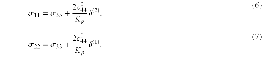
- 3. Qualitative interpretation of stress regime may be performed based on signs of anisotropic coefficients from (1) without knowing properties of the formation. Assume that from neighboring fields we only know that sign of third-order non-linear constants c 155 and C456 for an interested horizon is negative (usual case for rocks). It implies that coefficients Kp and Ks from equations (1) are also negative. From equations (6)-(7) we immediately estimate that δ(1)0 and δ(2)
 0 implies σ22
 σ33σ11. Alternatively the same conclusion may be obtained from equations (9)-(10) and relationships: γ(1)0 and γ(2)0. Finally, from δ(3)0 and equation (8) we confirm that σ22σ11. By using all anisotropic coefficients, we obtain independent estimates that should agree with each other if anisotropy is stress-induced.
 - Assuming all principal stresses to be compressive (negative) at this stage we predicted the stress regime σ 22σ33σ11 and found that minimum and maximum principal stresses are horizontal with orientations N20°E and N110°E respectively, whereas intermediate one is vertical.
- 4. Quantitative estimates of stress magnitudes may be accomplished only if at least one non-linear constant of the formation is known as well as magnitude of vertical stress. Estimated formation properties and vertical stress used for the inversion are listed against actual ones in the Table 1.
TABLE 1 Comparison of the actual model parameters with their estimations [formulae (4) and (3)] used for stress magnitudes inversion. c456, GPa λ, GPa μ, GPa σ33, MPa Estimated −35.3 5.35 0.82 −12 Actual −35.3 5.32 0.78 −12 - In this example, it is assumed that the exact value of only one constant c 456 is known from either borehole (Sinha and Kostek, 1995) or core measurements (Bakulin and Bakulin, 1990). Lame parameters of unstressed rock are approximated by seismic vertical velocities from equations (3). Vertical stress σ33 is estimated from equation (4) taking depth from seismic data z=600 m and average formation density 2050 kg/m3.
- Equations (9)-(10) are inverted for stress magnitudes and then the value of c 155 is estimated from equation (6) (Table 2). When value of c155 is known, another estimate of σ22 (Table 2, in brackets) may be obtained from equation (7).
TABLE 2 Comparison of the actual stresses with those estimated by inverting the anisotropic coefficients [equations˜ (6) -- (10)] and using approximate formation properties from Table 1. σ11, MPa σ22, MPa c155, GPa Estimated −7.5 −18.3 (−19.1) −140.2 Actual −8 −18 −158.5 - The example shows that the method provides estimated orientations and magnitudes of principal stresses with enough accuracy to be used in a variety of applications in oil and gas industry, mining, construction etc. Although in this discussion we have used weak-anisotropy approximations for the inversion, precise numerical inversion can be performed using exact equations (11)-(19), (23)-(24).
- Pore pressure estimation
- According to the invention, the described methods can also be used to estimate pore pressure. Under stress, the vertical P- and S- wave velocities are related by the expressions (23) and can simplified when using the fact that for rocks c ijkcmn 0Tpq:
- V P0 =c 33 =c 33 0 =c 111 E 33 +c 112(E 11 +E 22) (25)
- V S0=c55c44 0+c144E22+c155(E11+E33) (S-wave polarized in the x1-direction) where Tij and Eij are effective principal stresses and strains related by Hooke's law (equation 24), c33 0, c44 0 are the second-order elastic constants of rock and c111, c112, c144, c155 are the third-order nonlinear elastic constants (see the discussion below called “Stress dependence of effective elastic constants”).
- The pore fluid pressure is further estimated using vertical effective stress T 33 (estimated when solving numerically equations (23)) and vertical total effective stress σ33. Then, pore pressure is P=σ33−T33. As used herein the term “pore pressure” refers to the pore fluid pressure.
- Alternatively, the pore pressure can also be estimated using the knowledge of the total principal stresses σ 11, σ22, σ33 given above, one of the equations (25) for the vertical velocities VP0 and VS0 and equation (24). Some redundancy is provided with the non-used vertical velocity equation.
- Seismic monitoring of stress magnitudes
- The described process of estimating stress magnitudes and pore pressure using calibrated relationships (23) or approximate ones (1) can be also repeated at different time steps.
- Anisotropic parameters for orthorhombic media
- The basic set of the anisotropic parameters for orthorhombic media was introduced by Tsvankin (1997). His notation contains the vertical velocities of the P-wave and the ones of the S-wave and seven dimensionless Thomsen-type anisotropic coefficients. The definitions of those parameters in terms of the stiffnesses c ij and density ρ are given below:
- V P0—the P-wave vertical velocity:

- V S0—the vertical velocity of the S-wave polarized in the x1-direction:

- ε 2—the VTI parameter ε in the [x1, x3] symmetry plane normal to the x2-axis (this explains the superscript “2” of ε):

- δ (2)—the VTI parameter δ in the [x1, x3] plane:

- γ (2)—the VTI parameter γ in the [x1, x3] plane:

- ε (1)—the VTI parameter ε in the [x2, x3] symmetry plane:

- δ (1)—the VTI parameter δ in the [x2, x3] plane:

- γ (1)—the VTI parameter γ in the [x2, x3] plane:

- δ (3)—the VTI parameter δ in the [x1, x2] plane:

- These nine parameters fully describe wave propagation in general orthorhombic media. In particular applications, however, it is convenient to operate with specific combinations of Tsvankin's parameters. For example, P-wave NMO velocity from dipping reflectors depends on three coefficients η, which determine the anellipticity of the P-wave slowness in the symmetry planes (Grechka and Tsvankin, 1999). The definitions of η (1,2,3) are analogous to that of Alkhalifah-Tsvankin coefficient η in VTI media:
- η (1)—the VTI parameter η in the [x2, x3] plane:

- η (2)—the VTI parameter η in the [x1, x3] plane:

- η (3)—the VTI parameter η in the [x1, x2] plane:

- Stress dependence of effective elastic constants
- We assume that medium in the reference state is isotropic with two elastic constants (c 11 0=c33 0, c44 0=c66 0, c12 0=c13 0=c11 0−2c66 0 or Lame parameters λ=c33 0−2c44 0 and μ=c44 0). Reference state is assumed to be either unstressed or some fixed hydrostatic stressed state. Magnitudes of three principal stresses and strains are measured with respect to the stress and strain in the reference state. To characterize the behavior of isotropic material under stress, one needs three third-order (non-linear) elastic constants taken here as c111, c112, and c123 (Sinha and Kostek, 1995). In this case, triaxially stressed media is approximately equivalent to an orthorhombic anisotropic solid with the principal axes aligned with directions of principal stresses and stiffnesses given by equations (see, Sinha, B. K., 1982, Elastic waves in crystals under a bias: Ferroelectrics, 41, 61-73; Bakulin, A., Troyan, V., and Bakulin, V., 2000c, Acoustoelasticity of rocks: St. Petersburg Univ. Press; and Prioul et al., 2001):

- where c 111, c112, c123, are the three third-order (non-linear) elastic constants (c144=(c112−c123)/2,c155=(c111−c112)/4),
- Principal stresses and strains T ij and E ij are related by Hooke's law for the unstressed isotropic rock:

- where c 11 0=c33 0, c44 0=c66 0, c12 0=c13 0=c11 0−2c66 0.
- While the invention has been described in conjunction with the exemplary embodiments described above, many equivalent modifications and variations will be apparent to those skilled in the art when given this disclosure. Accordingly, the exemplary embodiments of the invention set forth above are considered to be illustrative and not limiting. Various changes to the described embodiments may be made without departing from the spirit and scope of the invention.
Claims (45)
1. A method for estimating stress characteristics from seismic data comprising:
receiving seismic data acquired using a plurality of sensors adapted to sense seismic energy, the seismic data representing subterranean characteristics within a subterranean region;
receiving properties of rock at a location within the subterranean region; and
estimating one or more stress characteristics for at least a sub-region in said region by combining the seismic data and the rock properties using a relationship between the stress characteristics in the sub-region and elastic stiffness and/or sonic velocity in the sub-region.
2. The method of claim 1 wherein the relationship is based on an effective medium theory.
3. The method of claim 2 wherein the relationship is based on a non-linear elasticity theory.
4. The method of claim 1 wherein the elastic stiffness and/or sonic velocity in the sub-region is obtained from the seismic data and the rock properties.
5. The method of claim 1 wherein the stress characteristics being estimated comprise the whole stress tensor.
6. The method of claim 1 wherein the elastic stiffness comprises elastic constants of the rock, and said step of estimating comprising deriving the elastic constants from the received rock properties.
7. The method of claim 6 wherein the elastic constants include second and third order elastic constants.
8. The method of claim 1 wherein the stress characteristics are effective stress characteristics.
9. The method of claim 1 wherein the stress characteristics are total stress characteristics.
10. The method of claim 1 wherein the estimation step comprises:
analyzing in the seismic data azimuth and offset dependence of seismic signatures for seismic anisotropy thereby determining a set of anisotropic coefficients;
identifying directions of minimum, intermediate and maximum stresses from orientation of principal axes of seismic anisotropy and signs of the anisotropic coefficients; and
inverting said anisotropic coefficients thereby estimating magnitudes of principal stresses in the sub-region using non-linear elastic constants and vertical total stress information derived from the rock properties.
11. The method of claim 1 wherein the sub-region is at least 5 meters away from a nearest existing borehole.
12. The method of claim 1 wherein said estimation step comprises estimating the orientations of principal stress in the sub-region.
13. The method of claim 12 wherein the orientations are estimated using axes of NMO ellipses p-wave and s-wave from a horizontal reflector.
14. The method of claim 12 wherein the orientations are estimated using p-wave and s-wave slowness surface.
15. The method of claim 1 wherein the relationship relies on an assumption of stressed rock weak anisotropy.
16. The method of claim 1 wherein the step of estimating comprises the step of relating vertical sonic velocities and anisotropic coefficients from the seismic data to effective stress magnitudes.
17. The method of claim 1 wherein the rock properties are estimated from laboratory core measurements.
18. The method of claim 1 wherein the rock properties are estimated from measurements made within a borehole.
19. The method of claim 18 wherein the measurements are of nonlinear properties of the rock and are made using a sonic logging tool while changing pressure in the borehole.
20. The method of claim 1 wherein the rock properties are approximated using a relationship similar to the formulae μ=c44 0=ρVS0 2, and λ=c33 0−2c44 0=ρVP0 2−2μ.
21. The method of claim 1 wherein the one or more stress characteristics include magnitude of principal stress.
22. The method of claim 1 wherein the sub-region includes a layer or rock having similar rock properties.
23. The method of claim 1 wherein the seismic data is acquired using 3D p-wave and s-wave surface geophones.
24. The method of claim 1 wherein the seismic data is acquired using multi-azimuth and multi-offset sources in combination with borehole measurements.
25. The method of claim 1 wherein the seismic data is acquired using one or more multicomponent ocean bottom cables.
26. The method of claim 1 wherein the sub-region intersects a trajectory for a planned borehole.
27. The method of claim 1 wherein the sub-region includes area greater than 100 square meters.
28. The method of claim 1 further comprising the step of estimating pore pressure in the sub-region using a relationship between pore pressure in the sub-region and elastic stiffness and/or sonic velocity in the sub-region.
29. The method of claim 1 further comprising the step of repeating the step of estimating for further sub-regions within said region.
30. The method of claim 1 further comprising the step of:
receiving a second set of seismic data representing subterranean characteristics at a different time; and
repeating said step of estimating for said sub-region using said second set of seismic data.
31. A method for estimating pore pressure from seismic data comprising:
receiving seismic data acquired using a plurality of sensors adapted to sense seismic energy, the seismic data representing subterranean characteristics within a subterranean region;
receiving properties of a rock formation within the region; and
estimating pore pressure for at least a sub-region in said region by combining the seismic data and the rock properties using a relationship between the pore pressure in the sub-region and elastic stiffness and/or sonic velocity in the sub-region.
32. The method of claim 31 wherein the sub-region is at least 5 meters away from a nearest existing borehole.
33. The method of claim 31 wherein the relationship is based on an effective medium theory.
34. The method of claim 33 wherein the relationship is based on a non-linear elasticity theory.
35. The method of claim 31 further comprising the step of repeating the step of estimating for further sub-regions within said region.
36. The method of claim 31 further comprising the step of:
receiving a second set of seismic data representing subterranean characteristics at a different time; and
repeating said step of estimating for said sub-region using said second set of seismic data.
37. A system for estimating stress characteristics from seismic data comprising a processor programmed to estimate one or more stress characteristics for at least a sub-region in a subterranean region that is at least 5 meters away from a nearest existing borehole by combining seismic data representing subterranean characteristics within the region and properties of rock at allocation within the region using a relationship between the stress characteristics in the sub-region and elastic stiffness or sonic velocity in the sub-region.
38. The system of claim 37 wherein the relationship is based on an effective medium theory.
39. The method of claim 38 wherein the relationship is based on a non-linear elasticity theory.
40. The system of claim 37 wherein the processor is further programmed to analyze in the seismic data azimuth and offset dependence of seismic signatures for seismic anisotropy thereby determining a set of anisotropic coefficients, identify directions of minimum, intermediate and maximum stresses from orientation of principal axes of seismic anisotropy and signs of the anisotropic coefficients, and invert said anisotropic coefficients thereby estimating magnitudes of principal stresses in the sub-region using non-linear elastic constants and vertical total stress information derived from the rock properties.
42. A computer readable medium that is capable of causing a computer to perform steps comprising:
receiving seismic data acquired using a plurality of sensors adapted to sense seismic energy, the seismic data representing subterranean characteristics within a subterranean region;
receiving properties of rock at a location within the subterranean region; and
estimating one or more stress characteristics for at least a sub-region in said region by combining the seismic data and the rock properties using a relationship between the stress characteristics in the sub-region and elastic stiffness and/or sonic velocity in the sub-region.
43. The computer readable medium of claim 42 wherein the sub-region is at least 5 meters away from a nearest existing borehole.
44. The computer readable medium of claim 42 wherein the relationship is based on an effective medium theory.
45. The computer readable medium of claim 44 wherein the relationship is based on a non-linear elasticity theory.
46. The computer readable medium of claim 42 further comprising the step of:
receiving a second set of seismic data representing subterranean characteristics at a different time; and
repeating said step of estimating for said sub-region using said second set of seismic data.
Priority Applications (5)
| Application Number | Priority Date | Filing Date | Title |
|---|---|---|---|
| US10/023,293 US6714873B2 (en) | 2001-12-17 | 2001-12-17 | System and method for estimating subsurface principal stresses from seismic reflection data |
| PCT/GB2002/005645 WO2003052459A1 (en) | 2001-12-17 | 2002-12-13 | System and method for estimating subsurface principal stresses from seismic reflection data |
| AU2002350952A AU2002350952A1 (en) | 2001-12-17 | 2002-12-13 | System and method for estimating subsurface principal stresses from seismic reflection data |
| EP02785664A EP1456694A1 (en) | 2001-12-17 | 2002-12-13 | System and method for estimating subsurface principal stresses from seismic reflection data |
| NO20043083A NO337603B1 (en) | 2001-12-17 | 2004-07-16 | System and method for estimating main subsurface voltages from seismic reflection data |
Applications Claiming Priority (1)
| Application Number | Priority Date | Filing Date | Title |
|---|---|---|---|
| US10/023,293 US6714873B2 (en) | 2001-12-17 | 2001-12-17 | System and method for estimating subsurface principal stresses from seismic reflection data |
Publications (2)
| Publication Number | Publication Date |
|---|---|
| US20030125878A1 true US20030125878A1 (en) | 2003-07-03 |
| US6714873B2 US6714873B2 (en) | 2004-03-30 |
Family
ID=21814225
Family Applications (1)
| Application Number | Title | Priority Date | Filing Date |
|---|---|---|---|
| US10/023,293 Expired - Lifetime US6714873B2 (en) | 2001-12-17 | 2001-12-17 | System and method for estimating subsurface principal stresses from seismic reflection data |
Country Status (5)
| Country | Link |
|---|---|
| US (1) | US6714873B2 (en) |
| EP (1) | EP1456694A1 (en) |
| AU (1) | AU2002350952A1 (en) |
| NO (1) | NO337603B1 (en) |
| WO (1) | WO2003052459A1 (en) |
Cited By (36)
| Publication number | Priority date | Publication date | Assignee | Title |
|---|---|---|---|---|
| US20040054478A1 (en) * | 2002-08-30 | 2004-03-18 | Brygynevych Valentyn Oleksandrovych | Method of wave diagnostics of the oil-and-gas-deposit |
| US20040223411A1 (en) * | 2003-01-15 | 2004-11-11 | Westerngeco L.L.C. | Method for retrieving local near-surface material information |
| WO2005040860A1 (en) * | 2003-10-24 | 2005-05-06 | Shell Internationale Research Maatschappij B.V. | Method and system for assessing pore fluid pressure behaviour in a subsurface formation |
| US20050149267A1 (en) * | 2003-10-24 | 2005-07-07 | Van Den Beukel Annemieke C. | Time-lapse seismic survey of a reservoir region |
| GB2422031A (en) * | 2005-01-07 | 2006-07-12 | Westerngeco Seismic Holdings | Determination of anisotropic physical characteristics in and around reservoirs |
| US20070038377A1 (en) * | 2005-08-08 | 2007-02-15 | Schlumberger Technology Corporation | Method and system for pre-drill pore pressure prediction |
| US20070165486A1 (en) * | 2006-01-19 | 2007-07-19 | Nicolae Moldoveanu | Methods and systems for efficiently acquiring towed streamer seismic surveys |
| US20070244647A1 (en) * | 2006-04-14 | 2007-10-18 | Dickson William C | Density and velocity based assessment method and apparatus |
| US20080033656A1 (en) * | 2005-01-07 | 2008-02-07 | Herwanger Jorg V | Processing a Seismic Monitor Survey |
| US20080178668A1 (en) * | 2006-12-22 | 2008-07-31 | Yan Gongrui | Method and apparatus for evaluating elastic mechanical properties of a transversely isotropic formation |
| US20080285381A1 (en) * | 2007-05-17 | 2008-11-20 | Nicolae Moldoveanu | Methods for Efficiently Acquiring Wide-Azimuth Towed Streamer Seismic Data |
| US20090122640A1 (en) * | 2007-05-17 | 2009-05-14 | David Ian Hill | Acquiring azimuth rich seismic data in the marine environment using a regular sparse pattern of continuously curved sail lines |
| US20090192716A1 (en) * | 2004-06-30 | 2009-07-30 | Menno Mathieu Molenaar | Determining in-situ the relation between seismic velocity and state of stress in an underground formation |
| US20090310439A1 (en) * | 2008-06-13 | 2009-12-17 | Johan Hauan | Method to determine the deviation of seismic equipment from a planned curved path |
| US20100016801A1 (en) * | 2008-07-16 | 2010-01-21 | Interrad Medical, Inc. | Anchor Systems and Methods |
| US20100063739A1 (en) * | 2006-11-14 | 2010-03-11 | Ragnar Slunga | Method for predicting where the next major earthquake will take place within an area |
| US20100118645A1 (en) * | 2008-11-08 | 2010-05-13 | Kenneth Welker | Coil shooting mode |
| US20100142317A1 (en) * | 2008-05-15 | 2010-06-10 | Nicolae Moldoveanu | Multi-vessel coil shooting acquisition |
| US20100250214A1 (en) * | 2009-03-27 | 2010-09-30 | Schlumberger Technology Corporation | Methods to estimate subsurface deviatoric stress characteristics from borehole sonic log anisotropy directions and image log failure directions |
| US20110030467A1 (en) * | 2007-11-30 | 2011-02-10 | Andrey Victorovich Bakulin | Real-time completion monitoring with acoustic waves |
| US20110158042A1 (en) * | 2009-12-30 | 2011-06-30 | Nicolae Moldoveanu | Randomization of Data Acquisition in Marine Seismic and Electromagnetic Acquisition |
| WO2011091367A1 (en) | 2010-01-25 | 2011-07-28 | CGGVeritas Services (U.S.) Inc. | Methods and systems for estimating stress using seismic data |
| WO2012148768A1 (en) * | 2011-04-27 | 2012-11-01 | Xiaoqing Sun | Method and apparatus for laser-based non-contact three-dimensional borehole stress measurement and pristine stress estimation |
| WO2013048580A1 (en) * | 2011-09-26 | 2013-04-04 | Exxonmobil Upstream Research Company | S-wave anisotropy estimate by automated image registration |
| US20140111207A1 (en) * | 2013-12-31 | 2014-04-24 | AquaLocate LLC | System and Method for Deep Detection of Petroleum and Hydrocarbon Deposits |
| US8711654B2 (en) | 2009-12-30 | 2014-04-29 | Westerngeco L.L.C. | Random sampling for geophysical acquisitions |
| US8724426B2 (en) | 2008-06-03 | 2014-05-13 | Westerngeco L.L.C. | Marine seismic streamer system configurations, systems, and methods for non-linear seismic survey navigation |
| CN104484573A (en) * | 2014-12-30 | 2015-04-01 | 中国石油天然气股份有限公司 | Novel calculating method for rigidity coefficient of stratum |
| US9103942B2 (en) | 2011-10-28 | 2015-08-11 | Westerngeco L.L.C. | Methods and systems for survey designs |
| WO2016105765A1 (en) * | 2014-12-23 | 2016-06-30 | Halliburton Energy Services, Inc. | Determining p-wave azimuthal anisotropy from walkaround vsp with offset dependent slowness corrections |
| US9594181B2 (en) | 2008-06-13 | 2017-03-14 | Westerngeco L.L.C. | Filtering and presentation of heading observations for coil shooting |
| US9857491B2 (en) | 2008-05-15 | 2018-01-02 | Westerngeco L.L.C. | Multi-vessel coil shooting acquisition |
| US20180203145A1 (en) * | 2017-01-13 | 2018-07-19 | Cgg Services Sas | Method and apparatus for unambiguously estimating seismic anisotropy parameters |
| US10379243B2 (en) * | 2014-03-28 | 2019-08-13 | Cgg Services Sas | Method and apparatus for characterizing azimuthal anisotropy using statistical moments |
| WO2020251725A1 (en) * | 2019-06-14 | 2020-12-17 | Halliburton Energy Services, Inc. | Estimation of formation elastic constants from drilling data |
| CN114486023A (en) * | 2022-01-19 | 2022-05-13 | 重庆交通大学 | Three-dimensional space stress characterization method for underground engineering disturbance surrounding rock area |
Families Citing this family (28)
| Publication number | Priority date | Publication date | Assignee | Title |
|---|---|---|---|---|
| US6751558B2 (en) * | 2001-03-13 | 2004-06-15 | Conoco Inc. | Method and process for prediction of subsurface fluid and rock pressures in the earth |
| US6785612B1 (en) * | 2003-05-29 | 2004-08-31 | Pgs Americas, Inc. | Seismic velocity update for anisotropic depth migration |
| GB0319201D0 (en) * | 2003-08-15 | 2003-09-17 | Westerngeco Ltd | Multi-component seismic data processing |
| US7042802B2 (en) * | 2003-09-18 | 2006-05-09 | Schlumberger Technology Corporation | Determination of stress characteristics of earth formations |
| US6901333B2 (en) * | 2003-10-27 | 2005-05-31 | Fugro N.V. | Method and device for the generation and application of anisotropic elastic parameters |
| US7761237B2 (en) * | 2004-11-18 | 2010-07-20 | Exxonmobil Upstream Research Co. | Method for quantification and mitigation for dip-induced azimuthal AVO |
| US7457194B2 (en) * | 2006-09-12 | 2008-11-25 | Schlumberger Technology Corporation | Discriminating natural fracture- and stress-induced sonic anisotropy using a combination of image and sonic logs |
| US7508735B2 (en) * | 2006-09-21 | 2009-03-24 | Shell Oil Company | Method of analyzing vertical seismic profile data, method of producing a hydrocarbon fluid, and a computer readable medium |
| US7460437B2 (en) * | 2007-01-03 | 2008-12-02 | Weinman Geoscience | Seismic data processing method and system for migration of seismic signals incorporating azimuthal variations in the velocity |
| US8885440B2 (en) * | 2007-01-05 | 2014-11-11 | Madhumita Sengupta | Constructing velocity models near salt bodies |
| US8098543B2 (en) * | 2007-01-05 | 2012-01-17 | Westerngeco L.L.C. | Estimation of stress and elastic parameters |
| US7593907B2 (en) * | 2007-02-20 | 2009-09-22 | Caitlin J. Ahrens | Method for forecasting earthquakes: based on P-ring junctions from seed earthquakes with tectonic plate edges and major fault lines |
| US8347959B2 (en) * | 2007-09-04 | 2013-01-08 | Terratek, Inc. | Method and system for increasing production of a reservoir |
| US8730761B2 (en) * | 2007-12-17 | 2014-05-20 | Westerngeco L.L.C. | Attenuating noise in seismic data |
| US9477002B2 (en) * | 2007-12-21 | 2016-10-25 | Schlumberger Technology Corporation | Microhydraulic fracturing with downhole acoustic measurement |
| US8121792B2 (en) * | 2008-03-31 | 2012-02-21 | Exxonmobil Upstream Research Co. | Integration of geomechanics and seismic analysis for passive seismic feasibility analysis |
| EP2281213A1 (en) * | 2008-05-30 | 2011-02-09 | ION Geophysical Corporation | Electromagnetic exploration |
| US9207344B2 (en) * | 2008-06-05 | 2015-12-08 | Westerngeco L.L.C. | Combining geomechanical velocity modeling and tomographic update for velocity model building |
| US8223586B2 (en) * | 2008-10-30 | 2012-07-17 | Schlumberger Technology Corporation | Method and system to determine the geo-stresses regime factor Q from borehole sonic measurement modeling |
| US8750074B2 (en) * | 2008-11-25 | 2014-06-10 | Baker Hughes Incorporated | Anisotropic parameter determination |
| US8407007B2 (en) * | 2008-12-02 | 2013-03-26 | Baker Hughes Incorporated | Anisotropic depth velocity model estimation above the receiver array in walkaway or 3D VSP data |
| US9291539B2 (en) | 2011-03-17 | 2016-03-22 | Baker Hughes Incorporated | Downhole rebound hardness measurement while drilling or wireline logging |
| WO2013016470A2 (en) * | 2011-07-27 | 2013-01-31 | Schlumberger Technology B.V. | Multi-well anisotropy inversion |
| US9310500B2 (en) * | 2013-02-20 | 2016-04-12 | Chevron U.S.A. Inc. | Velocity models for processing seismic data based on basin modeling |
| EP3221556A4 (en) * | 2015-01-23 | 2018-10-10 | Halliburton Energy Services, Inc. | A combination model for predicting stiffness coefficients absent stoneley wave velocity data |
| AU2016403404A1 (en) * | 2016-04-19 | 2018-08-16 | Halliburton Energy Services, Inc. | Fracture and stress characterization using layer thickness variation |
| RU2018146424A (en) * | 2016-06-01 | 2020-07-10 | Шлюмбергер Текнолоджи Б.В. | EVALUATION OF HORIZONTAL STRESSES AND NONLINEAR CONSTANTS IN ANISOTROPIC LAYERS, SUCH AS MOVING CARBONATE LAYERS IN ORGANOGENIC SHALE COLLECTORS |
| WO2021087501A1 (en) | 2019-10-31 | 2021-05-06 | Exxonmobil Upstream Research Company | System and methods for estimating subsurface horizontal principal stresses in anisotropic formations |
Family Cites Families (9)
| Publication number | Priority date | Publication date | Assignee | Title |
|---|---|---|---|---|
| SU1552088A1 (en) | 1988-06-02 | 1990-03-23 | А. В. Бакулин и В. Н. Бакулин | Apparatus for investigating mechanical characteristics of materials |
| US5060203A (en) | 1990-06-26 | 1991-10-22 | Chevron Research And Technology Company | Method of layer stripping to predict subsurface stress regimes |
| GB2278920B (en) * | 1993-06-07 | 1996-10-30 | Geco As | Method of determining earth elastic parameters in anistropic media |
| US5475650A (en) * | 1993-11-19 | 1995-12-12 | Schlumberger Technology Corporation | Measurement of nonlinear properties of formation using sonic borehole tool while changing pressure in borehole |
| US5398215A (en) * | 1993-11-19 | 1995-03-14 | Schlumberger Technology Corporation | Identification of stress induced anisotropy in formations |
| US5838633A (en) * | 1997-01-27 | 1998-11-17 | Schlumberger Technology Corporation | Method for estimating formation in-situ stress magnitudes using a sonic borehole tool |
| US6480790B1 (en) * | 1999-10-29 | 2002-11-12 | Exxonmobil Upstream Research Company | Process for constructing three-dimensional geologic models having adjustable geologic interfaces |
| US6351991B1 (en) * | 2000-06-05 | 2002-03-05 | Schlumberger Technology Corporation | Determining stress parameters of formations from multi-mode velocity data |
| US6473696B1 (en) * | 2001-03-13 | 2002-10-29 | Conoco Inc. | Method and process for prediction of subsurface fluid and rock pressures in the earth |
-
2001
- 2001-12-17 US US10/023,293 patent/US6714873B2/en not_active Expired - Lifetime
-
2002
- 2002-12-13 AU AU2002350952A patent/AU2002350952A1/en not_active Abandoned
- 2002-12-13 EP EP02785664A patent/EP1456694A1/en not_active Withdrawn
- 2002-12-13 WO PCT/GB2002/005645 patent/WO2003052459A1/en not_active Application Discontinuation
-
2004
- 2004-07-16 NO NO20043083A patent/NO337603B1/en not_active IP Right Cessation
Cited By (75)
| Publication number | Priority date | Publication date | Assignee | Title |
|---|---|---|---|---|
| US6954402B2 (en) * | 2002-08-30 | 2005-10-11 | Brygynevych Valentyn Oleksandr | Method of wave diagnostics of the oil-and-gas-deposit |
| US20040054478A1 (en) * | 2002-08-30 | 2004-03-18 | Brygynevych Valentyn Oleksandrovych | Method of wave diagnostics of the oil-and-gas-deposit |
| US20040223411A1 (en) * | 2003-01-15 | 2004-11-11 | Westerngeco L.L.C. | Method for retrieving local near-surface material information |
| US7154812B2 (en) * | 2003-01-15 | 2006-12-26 | Westerngeco L.L.C. | Method for retrieving local near-surface material information |
| EA009033B1 (en) * | 2003-10-24 | 2007-10-26 | Шелл Интернэшнл Рисерч Маатсхаппий Б.В. | Method and system for assessing pore fluid behavior in a subsurface formation |
| US20050149267A1 (en) * | 2003-10-24 | 2005-07-07 | Van Den Beukel Annemieke C. | Time-lapse seismic survey of a reservoir region |
| US7529625B2 (en) | 2003-10-24 | 2009-05-05 | Shell Oil Company | Method and system for assessing pore fluid pressure behaviour in a subsurface formation |
| US20070083332A1 (en) * | 2003-10-24 | 2007-04-12 | Philippus De Bree | Method and system for assessing pore fluid pressure behaviour in a subsurface formation |
| US7242637B2 (en) | 2003-10-24 | 2007-07-10 | Shell Oil Company | Time-lapse seismic survey of a reservoir region |
| WO2005040860A1 (en) * | 2003-10-24 | 2005-05-06 | Shell Internationale Research Maatschappij B.V. | Method and system for assessing pore fluid pressure behaviour in a subsurface formation |
| US7751979B2 (en) | 2004-06-30 | 2010-07-06 | Shell Oil Company | Determining in-situ the relation between seismic velocity and state of stress in an underground formation |
| US20090192716A1 (en) * | 2004-06-30 | 2009-07-30 | Menno Mathieu Molenaar | Determining in-situ the relation between seismic velocity and state of stress in an underground formation |
| US20060153005A1 (en) * | 2005-01-07 | 2006-07-13 | Herwanger Jorg V | Determination of anisotropic physical characteristics in and around reservoirs |
| US7859943B2 (en) | 2005-01-07 | 2010-12-28 | Westerngeco L.L.C. | Processing a seismic monitor survey |
| US20080033656A1 (en) * | 2005-01-07 | 2008-02-07 | Herwanger Jorg V | Processing a Seismic Monitor Survey |
| GB2422031B (en) * | 2005-01-07 | 2010-08-11 | Westerngeco Seismic Holdings | Determination of anisotropic physical characteristics in and around reservoirs |
| GB2422031A (en) * | 2005-01-07 | 2006-07-12 | Westerngeco Seismic Holdings | Determination of anisotropic physical characteristics in and around reservoirs |
| US7299132B2 (en) * | 2005-08-08 | 2007-11-20 | Schlumberger Technology Corp. | Method and system for pre-drill pore pressure prediction |
| US20070038377A1 (en) * | 2005-08-08 | 2007-02-15 | Schlumberger Technology Corporation | Method and system for pre-drill pore pressure prediction |
| US7400552B2 (en) | 2006-01-19 | 2008-07-15 | Westerngeco L.L.C. | Methods and systems for efficiently acquiring towed streamer seismic surveys |
| US8760964B2 (en) | 2006-01-19 | 2014-06-24 | Westerngeco L.L.C. | Methods and systems for efficiently acquiring towed streamer seismic surveys |
| US20100027374A1 (en) * | 2006-01-19 | 2010-02-04 | Westerngeco, L.L.C. | Methods and Systems for Efficiently Acquiring Towed Streamer Seismic Surveys |
| US20080267010A1 (en) * | 2006-01-19 | 2008-10-30 | Westerngeco L. L. C. | Methods and Systems for Efficiently Acquiring Towed Streamer Seismic Surveys |
| US9869787B2 (en) | 2006-01-19 | 2018-01-16 | Westerngeco L.L.C. | Methods and systems for efficiently acquiring towed streamer seismic surveys |
| US20070165486A1 (en) * | 2006-01-19 | 2007-07-19 | Nicolae Moldoveanu | Methods and systems for efficiently acquiring towed streamer seismic surveys |
| US20070244647A1 (en) * | 2006-04-14 | 2007-10-18 | Dickson William C | Density and velocity based assessment method and apparatus |
| US7440854B2 (en) | 2006-04-14 | 2008-10-21 | William Christian Dickson | Density and velocity based assessment method and apparatus |
| US20100063739A1 (en) * | 2006-11-14 | 2010-03-11 | Ragnar Slunga | Method for predicting where the next major earthquake will take place within an area |
| US20080178668A1 (en) * | 2006-12-22 | 2008-07-31 | Yan Gongrui | Method and apparatus for evaluating elastic mechanical properties of a transversely isotropic formation |
| US7751980B2 (en) * | 2006-12-22 | 2010-07-06 | Schlumberger Technology Corporation | Method and apparatus for evaluating elastic mechanical properties of a transversely isotropic formation |
| US20080285381A1 (en) * | 2007-05-17 | 2008-11-20 | Nicolae Moldoveanu | Methods for Efficiently Acquiring Wide-Azimuth Towed Streamer Seismic Data |
| US8908469B2 (en) | 2007-05-17 | 2014-12-09 | Westerngeco L.L.C. | Acquiring azimuth rich seismic data in the marine environment using a regular sparse pattern of continuously curved sail lines |
| US8559265B2 (en) | 2007-05-17 | 2013-10-15 | Westerngeco L.L.C. | Methods for efficiently acquiring wide-azimuth towed streamer seismic data |
| US8488409B2 (en) | 2007-05-17 | 2013-07-16 | Westerngeco L.L.C. | Acquiring azimuth rich seismic data in the marine environment using a regular sparse pattern of continuously curved sail lines |
| US20090122640A1 (en) * | 2007-05-17 | 2009-05-14 | David Ian Hill | Acquiring azimuth rich seismic data in the marine environment using a regular sparse pattern of continuously curved sail lines |
| US8635907B2 (en) | 2007-11-30 | 2014-01-28 | Shell Oil Company | Real-time completion monitoring with acoustic waves |
| US20110030467A1 (en) * | 2007-11-30 | 2011-02-10 | Andrey Victorovich Bakulin | Real-time completion monitoring with acoustic waves |
| US9766359B2 (en) | 2008-05-15 | 2017-09-19 | Westerngeco L.L.C. | Multi-vessel coil shooting acquisition |
| US9703000B2 (en) | 2008-05-15 | 2017-07-11 | Westerngeco L.L.C. | Multi-vessel coil shooting acquisition |
| US9857491B2 (en) | 2008-05-15 | 2018-01-02 | Westerngeco L.L.C. | Multi-vessel coil shooting acquisition |
| US20100142317A1 (en) * | 2008-05-15 | 2010-06-10 | Nicolae Moldoveanu | Multi-vessel coil shooting acquisition |
| US8681580B2 (en) | 2008-05-15 | 2014-03-25 | Westerngeco L.L.C. | Multi-vessel coil shooting acquisition |
| US8724426B2 (en) | 2008-06-03 | 2014-05-13 | Westerngeco L.L.C. | Marine seismic streamer system configurations, systems, and methods for non-linear seismic survey navigation |
| US10082589B2 (en) | 2008-06-13 | 2018-09-25 | Westerngeco L.L.C. | Method to determine the deviation of seismic equipment from a planned curved path |
| US20090310439A1 (en) * | 2008-06-13 | 2009-12-17 | Johan Hauan | Method to determine the deviation of seismic equipment from a planned curved path |
| US9052411B2 (en) | 2008-06-13 | 2015-06-09 | Westerngeco L.L.C. | Method to determine the deviation of seismic equipment from a planned curved path |
| US9594181B2 (en) | 2008-06-13 | 2017-03-14 | Westerngeco L.L.C. | Filtering and presentation of heading observations for coil shooting |
| US20100016801A1 (en) * | 2008-07-16 | 2010-01-21 | Interrad Medical, Inc. | Anchor Systems and Methods |
| US20100118645A1 (en) * | 2008-11-08 | 2010-05-13 | Kenneth Welker | Coil shooting mode |
| US8483008B2 (en) | 2008-11-08 | 2013-07-09 | Westerngeco L.L.C. | Coil shooting mode |
| US8117014B2 (en) * | 2009-03-27 | 2012-02-14 | Schlumberger Technology Corporation | Methods to estimate subsurface deviatoric stress characteristics from borehole sonic log anisotropy directions and image log failure directions |
| US20100250214A1 (en) * | 2009-03-27 | 2010-09-30 | Schlumberger Technology Corporation | Methods to estimate subsurface deviatoric stress characteristics from borehole sonic log anisotropy directions and image log failure directions |
| US20110158042A1 (en) * | 2009-12-30 | 2011-06-30 | Nicolae Moldoveanu | Randomization of Data Acquisition in Marine Seismic and Electromagnetic Acquisition |
| US8711654B2 (en) | 2009-12-30 | 2014-04-29 | Westerngeco L.L.C. | Random sampling for geophysical acquisitions |
| US8681581B2 (en) | 2009-12-30 | 2014-03-25 | Westerngeco L.L.C. | Randomization of data acquisition in marine seismic and electromagnetic acquisition |
| EP2529254A4 (en) * | 2010-01-25 | 2017-08-02 | CGG Veritas Services (U.S.) Inc. | Methods and systems for estimating stress using seismic data |
| WO2011091367A1 (en) | 2010-01-25 | 2011-07-28 | CGGVeritas Services (U.S.) Inc. | Methods and systems for estimating stress using seismic data |
| WO2012148768A1 (en) * | 2011-04-27 | 2012-11-01 | Xiaoqing Sun | Method and apparatus for laser-based non-contact three-dimensional borehole stress measurement and pristine stress estimation |
| WO2013048580A1 (en) * | 2011-09-26 | 2013-04-04 | Exxonmobil Upstream Research Company | S-wave anisotropy estimate by automated image registration |
| US9784863B2 (en) | 2011-09-26 | 2017-10-10 | Exxonmobil Upstream Research Company | S-wave anisotropy estimate by automated image registration |
| US9103942B2 (en) | 2011-10-28 | 2015-08-11 | Westerngeco L.L.C. | Methods and systems for survey designs |
| US20140111207A1 (en) * | 2013-12-31 | 2014-04-24 | AquaLocate LLC | System and Method for Deep Detection of Petroleum and Hydrocarbon Deposits |
| US10191174B2 (en) * | 2013-12-31 | 2019-01-29 | Longbranch Enterprises Inc. | System and method for deep detection of petroleum and hydrocarbon deposits |
| US9910177B2 (en) * | 2013-12-31 | 2018-03-06 | Longbranch Enterprises Inc. | System and method for deep detection of petroleum and hydrocarbon deposits |
| US10379243B2 (en) * | 2014-03-28 | 2019-08-13 | Cgg Services Sas | Method and apparatus for characterizing azimuthal anisotropy using statistical moments |
| US9684089B2 (en) * | 2014-12-23 | 2017-06-20 | Halliburton Energy Services, Inc. | Determining P-wave azimuthal anisotropy from walkaround VSP with offset dependent slowness corrections |
| WO2016105765A1 (en) * | 2014-12-23 | 2016-06-30 | Halliburton Energy Services, Inc. | Determining p-wave azimuthal anisotropy from walkaround vsp with offset dependent slowness corrections |
| US10031250B2 (en) | 2014-12-30 | 2018-07-24 | Petrochina Company Limited | Method and apparatus of determining stiffness coefficients of formation |
| CN104484573A (en) * | 2014-12-30 | 2015-04-01 | 中国石油天然气股份有限公司 | Novel calculating method for rigidity coefficient of stratum |
| AU2015275302B2 (en) * | 2014-12-30 | 2017-06-29 | Petrochina Company Limited | Method and apparatus of determining stiffness coefficients of formation |
| US20180203145A1 (en) * | 2017-01-13 | 2018-07-19 | Cgg Services Sas | Method and apparatus for unambiguously estimating seismic anisotropy parameters |
| US11243318B2 (en) * | 2017-01-13 | 2022-02-08 | Cgg Services Sas | Method and apparatus for unambiguously estimating seismic anisotropy parameters |
| WO2020251725A1 (en) * | 2019-06-14 | 2020-12-17 | Halliburton Energy Services, Inc. | Estimation of formation elastic constants from drilling data |
| US11174728B2 (en) | 2019-06-14 | 2021-11-16 | Halliburton Energy Services, Inc. | Estimation of formation elastic constants from drilling |
| CN114486023A (en) * | 2022-01-19 | 2022-05-13 | 重庆交通大学 | Three-dimensional space stress characterization method for underground engineering disturbance surrounding rock area |
Also Published As
| Publication number | Publication date |
|---|---|
| US6714873B2 (en) | 2004-03-30 |
| AU2002350952A1 (en) | 2003-06-30 |
| WO2003052459A1 (en) | 2003-06-26 |
| NO20043083L (en) | 2004-09-16 |
| EP1456694A1 (en) | 2004-09-15 |
| NO337603B1 (en) | 2016-05-09 |
Similar Documents
| Publication | Publication Date | Title |
|---|---|---|
| US6714873B2 (en) | System and method for estimating subsurface principal stresses from seismic reflection data | |
| US11015443B2 (en) | Estimation of horizontal stresses and nonlinear constants in anisotropic formations such as interbedded carbonate layers in organic-shale reservoirs | |
| US7042802B2 (en) | Determination of stress characteristics of earth formations | |
| US8117014B2 (en) | Methods to estimate subsurface deviatoric stress characteristics from borehole sonic log anisotropy directions and image log failure directions | |
| US9086508B2 (en) | Use of an effective tool model in sonic logging data processing | |
| US6714480B2 (en) | Determination of anisotropic moduli of earth formations | |
| US7859943B2 (en) | Processing a seismic monitor survey | |
| US7526385B2 (en) | Method, system and apparatus for determining rock strength using sonic logging | |
| US6611761B2 (en) | Sonic well logging for radial profiling | |
| Sinha et al. | Dipole dispersion crossover and sonic logs in a limestone reservoir | |
| US7679993B2 (en) | Method of characterizing a fractured reservoir using seismic reflection amplitudes | |
| US20060153005A1 (en) | Determination of anisotropic physical characteristics in and around reservoirs | |
| US20190293815A1 (en) | Elastic parameter estimation | |
| US20110246159A1 (en) | Method and Apparatus to Build a Three-Dimensional Mechanical Earth Model | |
| Gholami et al. | Application of in situ stress estimation methods in wellbore stability analysis under isotropic and anisotropic conditions | |
| Sinha et al. | Estimation of formation stresses using borehole sonic data | |
| US8831923B2 (en) | Method and system for determination of horizontal stresses from shear radial variation profiles | |
| Gajek et al. | Results of the downhole microseismic monitoring at a pilot hydraulic fracturing site in Poland—Part 1: Event location and stimulation performance | |
| Donald et al. | Stress characterization in deep boreholes using acoustoelasticity | |
| Peng et al. | Pressure in a fluid-filled borehole caused by a seismic source in stratified media | |
| Jeppson et al. | Acoustic evidence for a broad, hydraulically active damage zone surrounding the Alpine Fault, New Zealand | |
| Grant et al. | The application of VSP in the Pilbara | |
| Bouchou et al. | Advanced Borehole Acoustic Logging Measurements Applications and Their Contributions in Frac Design Optimization/A Case Study in Tight Carbonate, Tuba Reservoir, North Kuwait | |
| Gholami et al. | A new approach to determine geomechanical parameters of Vertical Transverse Isotropic media using VSP data | |
| Sinha | Recent advances in borehole sonic technology |
Legal Events
| Date | Code | Title | Description |
|---|---|---|---|
| AS | Assignment |
Owner name: SCHLUMBERGER TECHNOLOGY CORPORATION, CONNECTICUT Free format text: ASSIGNMENT OF ASSIGNORS INTEREST;ASSIGNORS:BAKULIN, ANDREY;SINHA, BIKASH K.;PRIOUL, ROMAIN CHARLES ANDRE;REEL/FRAME:012728/0705;SIGNING DATES FROM 20020104 TO 20020127 |
|
| STCF | Information on status: patent grant |
Free format text: PATENTED CASE |
|
| FPAY | Fee payment |
Year of fee payment: 4 |
|
| FPAY | Fee payment |
Year of fee payment: 8 |
|
| FPAY | Fee payment |
Year of fee payment: 12 |