US20020184824A1 - Movable barrier operator having cable tension sensor and door lock mechanism - Google Patents
Movable barrier operator having cable tension sensor and door lock mechanism Download PDFInfo
- Publication number
- US20020184824A1 US20020184824A1 US10/128,095 US12809502A US2002184824A1 US 20020184824 A1 US20020184824 A1 US 20020184824A1 US 12809502 A US12809502 A US 12809502A US 2002184824 A1 US2002184824 A1 US 2002184824A1
- Authority
- US
- United States
- Prior art keywords
- cable
- door
- accordance
- safety arrangement
- barrier
- Prior art date
- Legal status (The legal status is an assumption and is not a legal conclusion. Google has not performed a legal analysis and makes no representation as to the accuracy of the status listed.)
- Granted
Links
- 230000004888 barrier function Effects 0.000 title claims description 15
- 230000007246 mechanism Effects 0.000 title description 2
- 230000000903 blocking effect Effects 0.000 claims abstract description 13
- 230000002401 inhibitory effect Effects 0.000 claims 1
- 229910000831 Steel Inorganic materials 0.000 abstract description 2
- 239000010959 steel Substances 0.000 abstract description 2
- 239000004020 conductor Substances 0.000 description 6
- 239000004677 Nylon Substances 0.000 description 4
- 229920001778 nylon Polymers 0.000 description 4
- 230000008859 change Effects 0.000 description 1
- 230000007423 decrease Effects 0.000 description 1
- 238000001514 detection method Methods 0.000 description 1
- 238000010586 diagram Methods 0.000 description 1
- 230000004048 modification Effects 0.000 description 1
- 238000012986 modification Methods 0.000 description 1
- 230000003287 optical effect Effects 0.000 description 1
- 230000000246 remedial effect Effects 0.000 description 1
- 230000004044 response Effects 0.000 description 1
- 230000000717 retained effect Effects 0.000 description 1
- 125000006850 spacer group Chemical group 0.000 description 1
- 239000000725 suspension Substances 0.000 description 1
Images


Classifications
-
- E—FIXED CONSTRUCTIONS
- E05—LOCKS; KEYS; WINDOW OR DOOR FITTINGS; SAFES
- E05D—HINGES OR SUSPENSION DEVICES FOR DOORS, WINDOWS OR WINGS
- E05D13/00—Accessories for sliding or lifting wings, e.g. pulleys, safety catches
-
- E—FIXED CONSTRUCTIONS
- E05—LOCKS; KEYS; WINDOW OR DOOR FITTINGS; SAFES
- E05D—HINGES OR SUSPENSION DEVICES FOR DOORS, WINDOWS OR WINGS
- E05D13/00—Accessories for sliding or lifting wings, e.g. pulleys, safety catches
- E05D13/003—Anti-dropping devices
-
- E—FIXED CONSTRUCTIONS
- E05—LOCKS; KEYS; WINDOW OR DOOR FITTINGS; SAFES
- E05F—DEVICES FOR MOVING WINGS INTO OPEN OR CLOSED POSITION; CHECKS FOR WINGS; WING FITTINGS NOT OTHERWISE PROVIDED FOR, CONCERNED WITH THE FUNCTIONING OF THE WING
- E05F15/00—Power-operated mechanisms for wings
- E05F15/60—Power-operated mechanisms for wings using electrical actuators
- E05F15/603—Power-operated mechanisms for wings using electrical actuators using rotary electromotors
- E05F15/665—Power-operated mechanisms for wings using electrical actuators using rotary electromotors for vertically-sliding wings
- E05F15/668—Power-operated mechanisms for wings using electrical actuators using rotary electromotors for vertically-sliding wings for overhead wings
- E05F15/681—Power-operated mechanisms for wings using electrical actuators using rotary electromotors for vertically-sliding wings for overhead wings operated by flexible elongated pulling elements, e.g. belts
-
- E—FIXED CONSTRUCTIONS
- E06—DOORS, WINDOWS, SHUTTERS, OR ROLLER BLINDS IN GENERAL; LADDERS
- E06B—FIXED OR MOVABLE CLOSURES FOR OPENINGS IN BUILDINGS, VEHICLES, FENCES OR LIKE ENCLOSURES IN GENERAL, e.g. DOORS, WINDOWS, BLINDS, GATES
- E06B9/00—Screening or protective devices for wall or similar openings, with or without operating or securing mechanisms; Closures of similar construction
- E06B9/56—Operating, guiding or securing devices or arrangements for roll-type closures; Spring drums; Tape drums; Counterweighting arrangements therefor
- E06B9/80—Safety measures against dropping or unauthorised opening; Braking or immobilising devices; Devices for limiting unrolling
- E06B9/82—Safety measures against dropping or unauthorised opening; Braking or immobilising devices; Devices for limiting unrolling automatic
- E06B9/84—Safety measures against dropping or unauthorised opening; Braking or immobilising devices; Devices for limiting unrolling automatic against dropping
-
- E—FIXED CONSTRUCTIONS
- E05—LOCKS; KEYS; WINDOW OR DOOR FITTINGS; SAFES
- E05D—HINGES OR SUSPENSION DEVICES FOR DOORS, WINDOWS OR WINGS
- E05D13/00—Accessories for sliding or lifting wings, e.g. pulleys, safety catches
- E05D13/10—Counterbalance devices
- E05D13/12—Counterbalance devices with springs
- E05D13/1253—Counterbalance devices with springs with canted-coil torsion springs
- E05D13/1261—Counterbalance devices with springs with canted-coil torsion springs specially adapted for overhead wings
-
- E—FIXED CONSTRUCTIONS
- E05—LOCKS; KEYS; WINDOW OR DOOR FITTINGS; SAFES
- E05F—DEVICES FOR MOVING WINGS INTO OPEN OR CLOSED POSITION; CHECKS FOR WINGS; WING FITTINGS NOT OTHERWISE PROVIDED FOR, CONCERNED WITH THE FUNCTIONING OF THE WING
- E05F15/00—Power-operated mechanisms for wings
-
- E—FIXED CONSTRUCTIONS
- E05—LOCKS; KEYS; WINDOW OR DOOR FITTINGS; SAFES
- E05F—DEVICES FOR MOVING WINGS INTO OPEN OR CLOSED POSITION; CHECKS FOR WINGS; WING FITTINGS NOT OTHERWISE PROVIDED FOR, CONCERNED WITH THE FUNCTIONING OF THE WING
- E05F15/00—Power-operated mechanisms for wings
- E05F15/40—Safety devices, e.g. detection of obstructions or end positions
- E05F15/41—Detection by monitoring transmitted force or torque; Safety couplings with activation dependent upon torque or force, e.g. slip couplings
-
- E—FIXED CONSTRUCTIONS
- E05—LOCKS; KEYS; WINDOW OR DOOR FITTINGS; SAFES
- E05F—DEVICES FOR MOVING WINGS INTO OPEN OR CLOSED POSITION; CHECKS FOR WINGS; WING FITTINGS NOT OTHERWISE PROVIDED FOR, CONCERNED WITH THE FUNCTIONING OF THE WING
- E05F15/00—Power-operated mechanisms for wings
- E05F15/60—Power-operated mechanisms for wings using electrical actuators
- E05F15/603—Power-operated mechanisms for wings using electrical actuators using rotary electromotors
- E05F15/665—Power-operated mechanisms for wings using electrical actuators using rotary electromotors for vertically-sliding wings
- E05F15/668—Power-operated mechanisms for wings using electrical actuators using rotary electromotors for vertically-sliding wings for overhead wings
- E05F15/681—Power-operated mechanisms for wings using electrical actuators using rotary electromotors for vertically-sliding wings for overhead wings operated by flexible elongated pulling elements, e.g. belts
- E05F15/686—Power-operated mechanisms for wings using electrical actuators using rotary electromotors for vertically-sliding wings for overhead wings operated by flexible elongated pulling elements, e.g. belts by cables or ropes
-
- E—FIXED CONSTRUCTIONS
- E05—LOCKS; KEYS; WINDOW OR DOOR FITTINGS; SAFES
- E05Y—INDEXING SCHEME ASSOCIATED WITH SUBCLASSES E05D AND E05F, RELATING TO CONSTRUCTION ELEMENTS, ELECTRIC CONTROL, POWER SUPPLY, POWER SIGNAL OR TRANSMISSION, USER INTERFACES, MOUNTING OR COUPLING, DETAILS, ACCESSORIES, AUXILIARY OPERATIONS NOT OTHERWISE PROVIDED FOR, APPLICATION THEREOF
- E05Y2201/00—Constructional elements; Accessories therefor
- E05Y2201/60—Suspension or transmission members; Accessories therefor
- E05Y2201/622—Suspension or transmission members elements
- E05Y2201/644—Flexible elongated pulling elements
- E05Y2201/654—Cables
-
- E—FIXED CONSTRUCTIONS
- E05—LOCKS; KEYS; WINDOW OR DOOR FITTINGS; SAFES
- E05Y—INDEXING SCHEME ASSOCIATED WITH SUBCLASSES E05D AND E05F, RELATING TO CONSTRUCTION ELEMENTS, ELECTRIC CONTROL, POWER SUPPLY, POWER SIGNAL OR TRANSMISSION, USER INTERFACES, MOUNTING OR COUPLING, DETAILS, ACCESSORIES, AUXILIARY OPERATIONS NOT OTHERWISE PROVIDED FOR, APPLICATION THEREOF
- E05Y2201/00—Constructional elements; Accessories therefor
- E05Y2201/60—Suspension or transmission members; Accessories therefor
- E05Y2201/622—Suspension or transmission members elements
- E05Y2201/658—Members cooperating with flexible elongated pulling elements
- E05Y2201/672—Tensioners, tension sensors
-
- E—FIXED CONSTRUCTIONS
- E05—LOCKS; KEYS; WINDOW OR DOOR FITTINGS; SAFES
- E05Y—INDEXING SCHEME ASSOCIATED WITH SUBCLASSES E05D AND E05F, RELATING TO CONSTRUCTION ELEMENTS, ELECTRIC CONTROL, POWER SUPPLY, POWER SIGNAL OR TRANSMISSION, USER INTERFACES, MOUNTING OR COUPLING, DETAILS, ACCESSORIES, AUXILIARY OPERATIONS NOT OTHERWISE PROVIDED FOR, APPLICATION THEREOF
- E05Y2400/00—Electronic control; Electrical power; Power supply; Power or signal transmission; User interfaces
- E05Y2400/10—Electronic control
- E05Y2400/44—Sensors not directly associated with the wing movement
- E05Y2400/445—Switches
-
- E—FIXED CONSTRUCTIONS
- E05—LOCKS; KEYS; WINDOW OR DOOR FITTINGS; SAFES
- E05Y—INDEXING SCHEME ASSOCIATED WITH SUBCLASSES E05D AND E05F, RELATING TO CONSTRUCTION ELEMENTS, ELECTRIC CONTROL, POWER SUPPLY, POWER SIGNAL OR TRANSMISSION, USER INTERFACES, MOUNTING OR COUPLING, DETAILS, ACCESSORIES, AUXILIARY OPERATIONS NOT OTHERWISE PROVIDED FOR, APPLICATION THEREOF
- E05Y2400/00—Electronic control; Electrical power; Power supply; Power or signal transmission; User interfaces
- E05Y2400/10—Electronic control
- E05Y2400/52—Safety arrangements associated with the wing motor
- E05Y2400/53—Wing impact prevention or reduction
- E05Y2400/54—Obstruction or resistance detection
- E05Y2400/55—Obstruction or resistance detection by using load sensors
- E05Y2400/552—Switches
-
- E—FIXED CONSTRUCTIONS
- E05—LOCKS; KEYS; WINDOW OR DOOR FITTINGS; SAFES
- E05Y—INDEXING SCHEME ASSOCIATED WITH SUBCLASSES E05D AND E05F, RELATING TO CONSTRUCTION ELEMENTS, ELECTRIC CONTROL, POWER SUPPLY, POWER SIGNAL OR TRANSMISSION, USER INTERFACES, MOUNTING OR COUPLING, DETAILS, ACCESSORIES, AUXILIARY OPERATIONS NOT OTHERWISE PROVIDED FOR, APPLICATION THEREOF
- E05Y2400/00—Electronic control; Electrical power; Power supply; Power or signal transmission; User interfaces
- E05Y2400/80—User interfaces
- E05Y2400/85—User input means
- E05Y2400/852—Sensors
- E05Y2400/854—Switches
-
- E—FIXED CONSTRUCTIONS
- E05—LOCKS; KEYS; WINDOW OR DOOR FITTINGS; SAFES
- E05Y—INDEXING SCHEME ASSOCIATED WITH SUBCLASSES E05D AND E05F, RELATING TO CONSTRUCTION ELEMENTS, ELECTRIC CONTROL, POWER SUPPLY, POWER SIGNAL OR TRANSMISSION, USER INTERFACES, MOUNTING OR COUPLING, DETAILS, ACCESSORIES, AUXILIARY OPERATIONS NOT OTHERWISE PROVIDED FOR, APPLICATION THEREOF
- E05Y2800/00—Details, accessories and auxiliary operations not otherwise provided for
- E05Y2800/40—Physical or chemical protection
- E05Y2800/424—Physical or chemical protection against unintended use, e.g. protection against vandalism or sabotage
- E05Y2800/426—Physical or chemical protection against unintended use, e.g. protection against vandalism or sabotage against unauthorised use, e.g. keys
-
- E—FIXED CONSTRUCTIONS
- E05—LOCKS; KEYS; WINDOW OR DOOR FITTINGS; SAFES
- E05Y—INDEXING SCHEME ASSOCIATED WITH SUBCLASSES E05D AND E05F, RELATING TO CONSTRUCTION ELEMENTS, ELECTRIC CONTROL, POWER SUPPLY, POWER SIGNAL OR TRANSMISSION, USER INTERFACES, MOUNTING OR COUPLING, DETAILS, ACCESSORIES, AUXILIARY OPERATIONS NOT OTHERWISE PROVIDED FOR, APPLICATION THEREOF
- E05Y2900/00—Application of doors, windows, wings or fittings thereof
- E05Y2900/10—Application of doors, windows, wings or fittings thereof for buildings or parts thereof
- E05Y2900/106—Application of doors, windows, wings or fittings thereof for buildings or parts thereof for garages
Definitions
- the invention relates in general to barrier movement operators and in particular to a jack shaft garage door operator having a sensing apparatus for preventing cable associated with a pull-up cable drum from becoming slack during the operation of the door and for providing a positive door locking system.
- jack shaft garage door operators may present problems to the owners of the garage in that the cable may be payed out allowing the door to close under its own weight and if the door stalls or if the cable pay out drum rotates too far, the tension in the cable will drop and the cable may come off the drum necessitating a visit from a repairman.
- the jack shaft garage door operator does not provide any secure locking facility other than a lock at the bottom of the door, which may be tampered with by a burglar. If the door is not locked by some other means, the bottom lock may be forced or damaged and the door can be lifted open and the garage entered by an intruder.
- U.S. Pat. No. 3,785,809 discloses a door operator having a winch member built into a tilting door and movable with it.
- a cable is attached to a wall member supporting the door and another end of the cable is connected to an extensible arm.
- U.S. Pat. No. 2,185,828 discloses a catch for stopping a door from falling in the event that a sustaining cable or a counterbalance fails or breaks.
- U.S. Pat. No. 4,385,471 discloses a door including a stopping member having a clip connection 29 which engages a cable. If the cable breaks, as shown in FIG. 4, the arm 27 rotates outwardly bringing a cam dog 26 having a plurality of teeth 32 into locking engagement with a roller 13 a to prevent the roller 13 a from moving, thereby suspending the door in position.
- U.S. Pat. No. 4,520,591 to Calvagno discloses a system that is mechanically responsive to a break in a cable to prevent a door from falling.
- French Patent No. 2634-815-A includes an “antidrop” safety mechanism having a cam plate 21 on either side of the door equipped with a convex toothed edge to engage a bracket in case of door suspension failure. None of the aforementioned documents teach or disclose solutions for preventing a door from being opened or from stopping an operation of a garage door operator to cause it to reverse to take up cable which may have inadvertently been payed off a cable drum of a jack shaft door operator.
- a jack shaft garage door operator is useful for opening and closing a movable barrier such as a garage door.
- the jack shaft garage door operator embodying the present invention includes a drive unit having an electric motor therein for driving a torsion shaft sometimes called a jack shaft.
- the jack shaft is mounted above a door opening and usually has coupled to it a spring, or the like, for providing a restoring force to the jack shaft to help raise the door and to support a portion of the weight of the door that is not supported by the L-shaped rails that a door usually rides in.
- a pull-up cable drum is connected to the jack shaft to be rotated thereby and has a multi-strand steel pull-up cable connected thereto that may be payed out to lower a door or wound up to raise the door.
- the pull-up cable is typically connected to a bottom portion of the door and, when wound up, will cause the door to rise along vertical portions of L-shaped rails.
- a cable tension sensing apparatus is mounted on a wall having a door opening. The cable tension sensing apparatus includes cable guide to retain the cable a substantially fixed distance from the wall and a spring driven cable follower which urges against the cable extending between the drum periphery and the cable guide.
- An alerting switch is connected to the cable follower and sends a signal indicating loss of cable tension when the cable follower moves beyond a predetermined distance. Additionally, the movement of the cable follower moves a door blocking arrangement to a position to block movement of the door when being raised without use of the motor.
- the cable follower In the event that the cable is inadvertently payed out, for instance, by the door having reached the bottom of its travel and the operator continuing to run, the cable follower is allowed to move away from the wall by reduced tension (slack) in the cable and moves far enough that the alerting switch operates to generate a signal to which the operator responds by reversing the motor to raise the door.
- the garage door operator may otherwise be a conventional jack shaft garage door operator.
- the cable tension sensing apparatus prevents the cable from coming off the cable drum.
- a door stop for preventing the garage door from opening is attached to an upper panel of the garage door and, when in the closed position, is beneath the cable tension sensing apparatus when the door is pulled downwardly by full tension on the cable.
- FIG. 1 is a plan view of a portion of a garage having a garage door in a closed position with a jack shaft garage door operator associated therewith;
- FIG. 2 is a perspective view showing details of a portion of the jack shaft garage door operator shown in FIG. 1;
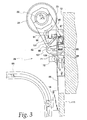
- FIG. 3 is a side view of a portion of the jack shaft garage door operator
- FIG. 4 is a side view, showing a cable tensioning member of the jack shaft garage door operator positioned to take up slack in a pull-up cable;
- FIGS. 5 a - 5 b is a circuit diagram showing portions of the electrical safety and control circuitry of the garage door opener
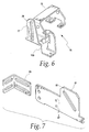
- FIG. 6 is a perspective view of a frame used in the embodiment
- FIG. 7 is a perspective view of a sliding member and door stop of the embodiment
- FIG. 8 is a perspective view of a portion of the pivot member and tension sensor.
- FIG. 9 is a perspective view of a tension sensor disabling apparatus.
- a jack shaft garage door operator embodying the present invention and generally identified by numeral 10 is shown therein.
- the jack shaft garage door operator 10 is mounted on a garage wall 12 near a garage door opening which has associated with it a movable multiple panel garage door 16 .
- the jack shaft garage door operator 10 includes a drive unit 20 having a motor 25 (FIG. 5 b ) which is connected by a chain drive system 21 to a jack shaft 22 .
- the motor 25 of drive unit 20 is energized in a well known manner to rotate the jack shaft 22 .
- Cable drums 24 and 24 ′ are mounted on the jack shaft 22 to be turned and respective pull-up cables 26 and 26 ′ are wound around the cable drums 24 and 24 ′ to be pulled upwardly.
- a cable tension assembly shown at 28 is mounted on the wall 12 of the garage immediately above the door 16 adjacent the jack shaft 22 .
- the garage door 16 is a multiple paneled door consisting of a plurality of rectangular panels 40 , 42 , 44 and 46 .
- the panels 40 and 42 are connected by a plurality of hinges 50 .
- Panels 42 and 44 are connected by a plurality of hinges 52 .
- Panels 44 and 46 are connected by a plurality of hinges 54 .
- the door is carried on a plurality of rollers in a pair of L-shaped tracks 60 , when the door 16 is lowered, the jack shaft 22 is rotated to pay out the cables 26 and 26 ′ from the pull-up cable drums 24 and 24 ′.
- Drive unit 20 includes a controller 27 shown in detail in FIG. 5 a - 5 b which responds to input signals to control the raising and lowering of door 16 by selectively stopping or energizing up and down rotation of motor 25 .
- Controller 27 responds to standard input signals in a known manner to raise and lower the door. Pushing a button 23 when the door is open or closed will cause a processor 31 of controller 27 to energize the motor 25 to move the door to the other state. Similarly, receipt of a properly encoded signal from a remote transmitter 29 (FIG. 1) at a receiver 33 will result in the processor 31 causing the door to open or close.
- the garage door operator includes infrared obstruction sensor apparatus comprising a transmitter 37 mounted on one side of the door and a receiver 35 mounted on the opposite side of the door.
- the transmitter 37 is aimed at the receiver 35 and transmits a recurring series of light pulses.
- the receiver 35 receives the light pulses and generates a series of electrical pulses on a conductor pair 39 connected to the controller 27 .
- the controller 27 also provides DC power to the transmitter 37 and receiver 35 via the conductor pair 39 to power their operation. Whenever the transmitted light beams from transmitter 37 to receiver 35 are blocked, the pulses on conductor 39 are terminated by receiver 35 .
- Processor 31 senses the stoppage of pulses and, when the door is traveling downward, the processor controls the motor 25 to stop and then to rotate to raise the door. Thus the door is kept from striking whatever is in the doorway blocking the light beam.
- the DC voltage which powers the operation of transmitter 37 is connected, in part, to transmitter 37 via a normally open contact 30 of a switch 32 .
- the closed state of contact 30 is maintained when tension is present in cable 26 .
- switch contact 30 opens and, the transmitter stops transmitting light pulses causing the pulses on conductors 39 to stop.
- controller 31 responds to the stoppage of pulses on conductors 39 by raising the door when the door was traveling down.
- FIG. 2 is a perspective view of cable tension assembly 28 as mounted to wall 12 near cable drum 24 .
- Cable tension assembly 28 includes a cable guide roller 71 which is rotatably mounted to wall 12 in a roller frame 72 . Cable 26 passes between roller 71 and wall 12 .
- FIG. 3 is a plan view of the cable tension assembly as viewed outwardly from the center of the door 16 . As shown in FIG. 3, roller 71 is rotatably held by assembly 72 at a distance from wall 12 which is substantially equal to the distance between wall 12 and the perimeter 73 of drum 24 . Thus, the perimeter 73 of drum 24 and the roller 71 keep cable running substantially parallel to the surface of wall 12 when tension is present in the cable 26 .
- Roller holding assembly 72 is a portion of a frame 75 (FIG. 6) which supports portions of the tension assembly 28 .
- Frame 75 includes a portion 77 which is substantially normal to the surface of wall 12 and includes a slot 79 which is also normal to wall 12 .
- Cable tension assembly 28 also includes a sliding member 81 (FIG. 7), which is slidably connected to frame 75 at slot 79 by means of a nylon slide 85 . More specifically a pair of screws 86 secure nylon slide 85 to a front face of portion 77 by means of two holes 87 in sliding member 81 . After such attachment, sliding member 81 on one side of portion 77 and nylon slide 85 on the other are free to move normally to wall 12 while trapped in slot 79 .
- a doorstop 83 may also be attached to sliding member 81 to stop the raising of door 16 by means other than motor 25 .
- a cable tension sensing pivot member 91 is used to sense the tension in cable 26 .
- Pivot member 91 is slidably mounted to jack shaft 22 and is free to rotate about the longitudinal axis of jack shaft 22 as represented by accurate arrow 95 (FIG. 3).
- Pivot member 91 includes a cable sensor 97 which, after mounting pivot member 91 , is placed between cable 26 and wall 12 .
- Pivot member 91 includes a protrusion 98 which after assembly of the cable tension apparatus 28 is slidably inserted into a slot 82 of sliding member 81 .
- Rotational force is applied to pivot member 91 by a torsion spring 101 which is disposed between protrusion 98 and a tab 103 of frame 75 . By the operation of spring 101 the pivot member 91 is urged to rotate in a clockwise direction as shown in FIG. 3.
- switch 32 is shown mounted to frame 75 and with a switch lever 107 disposed between a shelf 109 of nylon sliding member 85 and wall 12 .
- cable tension follower 97 is urged against the force of spring 101 and maintained in a position shown in FIG. 3.
- switch lever 107 is held by sliding member 85 and switch contact 30 of switch 32 is kept in the closed state.
- FIG. 4 shows the situation when the cable is not under tension such as would occur if the door 16 became stuck when being lowered or the motor continued to run after reaching the down limit.
- spring 101 causes pivot member 91 to rotate clockwise to a position shown in FIG. 4.
- pin 98 moves within slot 82 causing sliding member 75 to move away from wall 12 .
- the movement of sliding member 75 raises the switch lever 107 until switch contact 30 of switch 32 assumes its normally open state.
- the opening of switch contact 30 removes DC voltage from transmitter 37 which results in controller 27 sensing the absence of pulses on conductor 39 .
- the controller 27 responds to the absence of pulses by controlling motor to raise door 16 .
- motor 25 begins to turn the jack shaft 22 to raise the door, tension will be restored in cable 26 and the configuration shown in FIG. 3 will again be achieved.
- the sliding member 81 and a door stop extension 83 provide protection.
- the cable 26 will go slack as shown in FIG. 4.
- the slack cable will result in sliding member 81 moving away from the wall 12 .
- Affixed to sliding member 81 is a door stop 83 which moves translationally along with sliding member 81 .
- a spacer block 111 (FIG. 1) is attached to the inside of the top panel 40 of the door 16 and strikes the door stop 83 which stops the door from further movement.
- tension is present in the cable and, as shown in FIG. 3, the door stop is retained near wall 12 .
- the block 111 will freely pass the door stop 83 when it is held near the wall 12 .
- the door 16 may be closed and tension is removed from the cable 26 . This might result in a blocked door as represented in FIG. 4.
- an emergency release control is provided whereby a person inside the garage can raise the door.
- the release control includes a release cable or rope 123 and handle 121 as represented in FIGS. 1 and 9.
- the cable tension assembly 28 has been simplified for ease of understanding.
- the protrusion 98 is extended and is shown as 98 ′ in FIG. 9.
- the spring holding member 103 ′ is formed to more easily allow the rope or cable 123 to slide passed.
- the emergency release (FIG. 9) includes a cable or rope 123 connected to a user operated handle 121 at a free end and running up through guides 125 which are affixed to the wall 12 .
- the guides 125 retain the rope 123 in place and allow a 180° change in the rope's direction of movement.
- Rope 123 extends between the spring retainer 103 ′ and the wall 12 and passes over protrusion 98 ′ away from wall 12 .
- the rope 123 is then tied to an anchor 126 .
- an operator pulls downwardly on handle 121 which tightens cable 123 and moves protrusion 98 ′ and sliding member 81 back toward the wall 12 freeing tube door 16 to be raised.
- rope 123 may also be attached to a clutch in opener 20 to release the motor 25 from the chain assembly 21 to ease the manual raising of the door.
Landscapes
- Engineering & Computer Science (AREA)
- Structural Engineering (AREA)
- Mechanical Engineering (AREA)
- Architecture (AREA)
- Civil Engineering (AREA)
- Power-Operated Mechanisms For Wings (AREA)
- Operating, Guiding And Securing Of Roll- Type Closing Members (AREA)
Abstract
Description
- The invention relates in general to barrier movement operators and in particular to a jack shaft garage door operator having a sensing apparatus for preventing cable associated with a pull-up cable drum from becoming slack during the operation of the door and for providing a positive door locking system.
- One of the problems associated with jack shaft garage door operators is that while they are compact and may be conveniently used in garages which have little overhead room, they may present problems to the owners of the garage in that the cable may be payed out allowing the door to close under its own weight and if the door stalls or if the cable pay out drum rotates too far, the tension in the cable will drop and the cable may come off the drum necessitating a visit from a repairman. In addition, the jack shaft garage door operator does not provide any secure locking facility other than a lock at the bottom of the door, which may be tampered with by a burglar. If the door is not locked by some other means, the bottom lock may be forced or damaged and the door can be lifted open and the garage entered by an intruder.
- U.S. Pat. No. 3,785,809 discloses a door operator having a winch member built into a tilting door and movable with it. A cable is attached to a wall member supporting the door and another end of the cable is connected to an extensible arm.
- U.S. Pat. No. 2,185,828 discloses a catch for stopping a door from falling in the event that a sustaining cable or a counterbalance fails or breaks.
- U.S. Pat. No. 4,385,471 discloses a door including a stopping member having a
clip connection 29 which engages a cable. If the cable breaks, as shown in FIG. 4, thearm 27 rotates outwardly bringing acam dog 26 having a plurality ofteeth 32 into locking engagement with a roller 13 a to prevent the roller 13 a from moving, thereby suspending the door in position. - U.S. Pat. No. 4,520,591 to Calvagno discloses a system that is mechanically responsive to a break in a cable to prevent a door from falling.
- French Patent No. 2634-815-A includes an “antidrop” safety mechanism having a
cam plate 21 on either side of the door equipped with a convex toothed edge to engage a bracket in case of door suspension failure. None of the aforementioned documents teach or disclose solutions for preventing a door from being opened or from stopping an operation of a garage door operator to cause it to reverse to take up cable which may have inadvertently been payed off a cable drum of a jack shaft door operator. - What is needed is an improved barrier movement operator that avoids unwanted problems with the cable coming off the drum and provides security for the user.
- A jack shaft garage door operator is useful for opening and closing a movable barrier such as a garage door. The jack shaft garage door operator embodying the present invention includes a drive unit having an electric motor therein for driving a torsion shaft sometimes called a jack shaft. The jack shaft is mounted above a door opening and usually has coupled to it a spring, or the like, for providing a restoring force to the jack shaft to help raise the door and to support a portion of the weight of the door that is not supported by the L-shaped rails that a door usually rides in. A pull-up cable drum is connected to the jack shaft to be rotated thereby and has a multi-strand steel pull-up cable connected thereto that may be payed out to lower a door or wound up to raise the door. The pull-up cable is typically connected to a bottom portion of the door and, when wound up, will cause the door to rise along vertical portions of L-shaped rails. A cable tension sensing apparatus is mounted on a wall having a door opening. The cable tension sensing apparatus includes cable guide to retain the cable a substantially fixed distance from the wall and a spring driven cable follower which urges against the cable extending between the drum periphery and the cable guide. An alerting switch is connected to the cable follower and sends a signal indicating loss of cable tension when the cable follower moves beyond a predetermined distance. Additionally, the movement of the cable follower moves a door blocking arrangement to a position to block movement of the door when being raised without use of the motor.
- In the event that the cable is inadvertently payed out, for instance, by the door having reached the bottom of its travel and the operator continuing to run, the cable follower is allowed to move away from the wall by reduced tension (slack) in the cable and moves far enough that the alerting switch operates to generate a signal to which the operator responds by reversing the motor to raise the door. The garage door operator may otherwise be a conventional jack shaft garage door operator. The cable tension sensing apparatus prevents the cable from coming off the cable drum. In addition, a door stop for preventing the garage door from opening is attached to an upper panel of the garage door and, when in the closed position, is beneath the cable tension sensing apparatus when the door is pulled downwardly by full tension on the cable. When the cable follower moves as tension lessens in the cable, a sliding member is moved away from the wall above the door. If the door is attempted to be breached, for instance by an intruder attempting to lift the door, the cable becomes slack allowing the sliding member to come out from the wall so that it then engages compressionally a stop plate on the garage door thereby preventing further upward motion of the garage door.
- It is an aspect of the present invention to provide a jack shaft garage door operator having a cable tension sensor for providing door operator actions reversal to prevent cable paying off a cable drum.
- It is another aspect of the present invention to provide a jack shaft garage door operator having a door opening block adapted to engage a sliding member to prevent a door from being forced open.
- Other advantages of the invention will become obvious to one of ordinary skill in the art upon a perusal of the following specification and claims in light of the accompanying drawings.
- FIG. 1 is a plan view of a portion of a garage having a garage door in a closed position with a jack shaft garage door operator associated therewith;
- FIG. 2 is a perspective view showing details of a portion of the jack shaft garage door operator shown in FIG. 1;
- FIG. 3 is a side view of a portion of the jack shaft garage door operator;
- FIG. 4 is a side view, showing a cable tensioning member of the jack shaft garage door operator positioned to take up slack in a pull-up cable;
- FIGS. 5 a-5 b is a circuit diagram showing portions of the electrical safety and control circuitry of the garage door opener;
- FIG. 6 is a perspective view of a frame used in the embodiment;
- FIG. 7 is a perspective view of a sliding member and door stop of the embodiment;
- FIG. 8 is a perspective view of a portion of the pivot member and tension sensor; and
- FIG. 9 is a perspective view of a tension sensor disabling apparatus.
- Referring now to the drawings and especially to FIG. 1, a jack shaft garage door operator embodying the present invention and generally identified by
numeral 10 is shown therein. The jack shaftgarage door operator 10 is mounted on agarage wall 12 near a garage door opening which has associated with it a movable multiplepanel garage door 16. - The jack shaft
garage door operator 10 includes adrive unit 20 having a motor 25 (FIG. 5b) which is connected by achain drive system 21 to ajack shaft 22. Themotor 25 ofdrive unit 20 is energized in a well known manner to rotate thejack shaft 22.Cable drums jack shaft 22 to be turned and respective pull-upcables cable drums wall 12 of the garage immediately above thedoor 16 adjacent thejack shaft 22. - The
garage door 16 is a multiple paneled door consisting of a plurality ofrectangular panels panels hinges 50.Panels hinges 52.Panels hinges 54. The door is carried on a plurality of rollers in a pair of L-shaped tracks 60, when thedoor 16 is lowered, thejack shaft 22 is rotated to pay out thecables cable drums -
Drive unit 20 includes acontroller 27 shown in detail in FIG. 5a-5 b which responds to input signals to control the raising and lowering ofdoor 16 by selectively stopping or energizing up and down rotation ofmotor 25.Controller 27 responds to standard input signals in a known manner to raise and lower the door. Pushing abutton 23 when the door is open or closed will cause aprocessor 31 ofcontroller 27 to energize themotor 25 to move the door to the other state. Similarly, receipt of a properly encoded signal from a remote transmitter 29 (FIG. 1) at areceiver 33 will result in theprocessor 31 causing the door to open or close. - The garage door operator includes infrared obstruction sensor apparatus comprising a
transmitter 37 mounted on one side of the door and areceiver 35 mounted on the opposite side of the door. Thetransmitter 37 is aimed at thereceiver 35 and transmits a recurring series of light pulses. Thereceiver 35 receives the light pulses and generates a series of electrical pulses on aconductor pair 39 connected to thecontroller 27. It should be mentioned that thecontroller 27 also provides DC power to thetransmitter 37 andreceiver 35 via theconductor pair 39 to power their operation. Whenever the transmitted light beams fromtransmitter 37 toreceiver 35 are blocked, the pulses onconductor 39 are terminated byreceiver 35.Processor 31 senses the stoppage of pulses and, when the door is traveling downward, the processor controls themotor 25 to stop and then to rotate to raise the door. Thus the door is kept from striking whatever is in the doorway blocking the light beam. The DC voltage which powers the operation oftransmitter 37 is connected, in part, totransmitter 37 via a normallyopen contact 30 of aswitch 32. The closed state ofcontact 30 is maintained when tension is present incable 26. As is discussed later herein, when the tension incable 26 decreases switchcontact 30 opens and, the transmitter stops transmitting light pulses causing the pulses onconductors 39 to stop. As in the case of an optical obstruction,controller 31 responds to the stoppage of pulses onconductors 39 by raising the door when the door was traveling down. - FIG. 2 is a perspective view of
cable tension assembly 28 as mounted to wall 12 nearcable drum 24.Cable tension assembly 28 includes acable guide roller 71 which is rotatably mounted to wall 12 in aroller frame 72.Cable 26 passes betweenroller 71 andwall 12. FIG. 3 is a plan view of the cable tension assembly as viewed outwardly from the center of thedoor 16. As shown in FIG. 3,roller 71 is rotatably held byassembly 72 at a distance fromwall 12 which is substantially equal to the distance betweenwall 12 and theperimeter 73 ofdrum 24. Thus, theperimeter 73 ofdrum 24 and theroller 71 keep cable running substantially parallel to the surface ofwall 12 when tension is present in thecable 26. -
Roller holding assembly 72 is a portion of a frame 75 (FIG. 6) which supports portions of thetension assembly 28.Frame 75 includes aportion 77 which is substantially normal to the surface ofwall 12 and includes aslot 79 which is also normal towall 12.Cable tension assembly 28 also includes a sliding member 81 (FIG. 7), which is slidably connected to frame 75 atslot 79 by means of anylon slide 85. More specifically a pair ofscrews 86secure nylon slide 85 to a front face ofportion 77 by means of twoholes 87 in slidingmember 81. After such attachment, slidingmember 81 on one side ofportion 77 andnylon slide 85 on the other are free to move normally to wall 12 while trapped inslot 79. Adoorstop 83 may also be attached to slidingmember 81 to stop the raising ofdoor 16 by means other thanmotor 25. - A cable tension
sensing pivot member 91 is used to sense the tension incable 26.Pivot member 91 is slidably mounted tojack shaft 22 and is free to rotate about the longitudinal axis ofjack shaft 22 as represented by accurate arrow 95 (FIG. 3).Pivot member 91 includes acable sensor 97 which, after mountingpivot member 91, is placed betweencable 26 andwall 12.Pivot member 91 includes aprotrusion 98 which after assembly of thecable tension apparatus 28 is slidably inserted into aslot 82 of slidingmember 81. Rotational force is applied to pivotmember 91 by atorsion spring 101 which is disposed betweenprotrusion 98 and atab 103 offrame 75. By the operation ofspring 101 thepivot member 91 is urged to rotate in a clockwise direction as shown in FIG. 3. - It will be remembered that DC voltage is applied to the
infrared transmitter 37 via the normally open contact 30 (FIG. 5a) of aswitch 32. In FIG. 2, switch 32 is shown mounted to frame 75 and with aswitch lever 107 disposed between ashelf 109 ofnylon sliding member 85 andwall 12. When tension is present in cable 26 (FIG. 3) thecable tension follower 97 is urged against the force ofspring 101 and maintained in a position shown in FIG. 3. In the “tensioned” position of FIG. 3 theswitch lever 107 is held by slidingmember 85 andswitch contact 30 ofswitch 32 is kept in the closed state. Thus, when tension is present incable 26 the infrared obstruction detection system operates in a normal, well known manner. - Alternatively, FIG. 4 shows the situation when the cable is not under tension such as would occur if the
door 16 became stuck when being lowered or the motor continued to run after reaching the down limit. Without the counter force of cable tension oncable guide 97,spring 101 causespivot member 91 to rotate clockwise to a position shown in FIG. 4. Aspivot member 91 rotates, pin 98 moves withinslot 82 causing slidingmember 75 to move away fromwall 12. The movement of slidingmember 75 raises theswitch lever 107 untilswitch contact 30 ofswitch 32 assumes its normally open state. The opening ofswitch contact 30 removes DC voltage fromtransmitter 37 which results incontroller 27 sensing the absence of pulses onconductor 39. As described above, thecontroller 27 responds to the absence of pulses by controlling motor to raisedoor 16. Whenmotor 25 begins to turn thejack shaft 22 to raise the door, tension will be restored incable 26 and the configuration shown in FIG. 3 will again be achieved. - The raising of
door 16 in response to a lack of cable tension occurs only when thedoor 16 is being lowered bymotor 25. When the door is in the lowered/closed state,processor 31 does not respond to the removal of cable tension by energizingmotor 25 to raise the door. This occurs becauseprocessor 31 is programmed to perform a remedial opening of thedoor 16 only when the door is being closed under the control ofcontroller 27. - Should someone, such as a burglar, attempt to raise a
door 16, which is in the closed state, the slidingmember 81 and adoor stop extension 83 provide protection. When the door is closed and an attempt to raise it is made, thecable 26 will go slack as shown in FIG. 4. The slack cable will result in slidingmember 81 moving away from thewall 12. Affixed to slidingmember 81 is adoor stop 83 which moves translationally along with slidingmember 81. A spacer block 111 (FIG. 1) is attached to the inside of thetop panel 40 of thedoor 16 and strikes the door stop 83 which stops the door from further movement. Alternatively, when the door is being raised by the motor, tension is present in the cable and, as shown in FIG. 3, the door stop is retained nearwall 12. Theblock 111 will freely pass thedoor stop 83 when it is held near thewall 12. - Under certain conditions, such as the
door spring 120 breaking or coming loose, thedoor 16 may be closed and tension is removed from thecable 26. This might result in a blocked door as represented in FIG. 4. To prevent such, an emergency release control is provided whereby a person inside the garage can raise the door. The release control includes a release cable orrope 123 and handle 121 as represented in FIGS. 1 and 9. In FIG. 9 thecable tension assembly 28 has been simplified for ease of understanding. When the emergency release is present, theprotrusion 98 is extended and is shown as 98′ in FIG. 9. Also thespring holding member 103′ is formed to more easily allow the rope orcable 123 to slide passed. - The emergency release (FIG. 9) includes a cable or
rope 123 connected to a user operatedhandle 121 at a free end and running up throughguides 125 which are affixed to thewall 12. Theguides 125 retain therope 123 in place and allow a 180° change in the rope's direction of movement.Rope 123 extends between thespring retainer 103′ and thewall 12 and passes overprotrusion 98′ away fromwall 12. Therope 123 is then tied to ananchor 126. When the door block is to be manually controlled, an operator pulls downwardly onhandle 121 which tightenscable 123 and movesprotrusion 98′ and slidingmember 81 back toward thewall 12 freeingtube door 16 to be raised. Advantageously,rope 123 may also be attached to a clutch inopener 20 to release themotor 25 from thechain assembly 21 to ease the manual raising of the door. - The preceding description is intended to be illustrative of the principles of the invention and modifications can be made to the embodiment and still be within the scope of the invention recited in the appended claims. For example, the
torsion spring 120 of the preceding embodiment could be replaced by a counter weight. Further, the distance between the wall and cable tension assembly might be varied by the use of a shim to avoid the use ofmember 111 attached todoor 16.
Claims (19)
Priority Applications (1)
| Application Number | Priority Date | Filing Date | Title |
|---|---|---|---|
| US10/128,095 US6782662B2 (en) | 2001-04-25 | 2002-04-23 | Movable barrier operator having cable tension sensor and door lock mechanism |
Applications Claiming Priority (2)
| Application Number | Priority Date | Filing Date | Title |
|---|---|---|---|
| US28647201P | 2001-04-25 | 2001-04-25 | |
| US10/128,095 US6782662B2 (en) | 2001-04-25 | 2002-04-23 | Movable barrier operator having cable tension sensor and door lock mechanism |
Publications (2)
| Publication Number | Publication Date |
|---|---|
| US20020184824A1 true US20020184824A1 (en) | 2002-12-12 |
| US6782662B2 US6782662B2 (en) | 2004-08-31 |
Family
ID=23098754
Family Applications (1)
| Application Number | Title | Priority Date | Filing Date |
|---|---|---|---|
| US10/128,095 Expired - Lifetime US6782662B2 (en) | 2001-04-25 | 2002-04-23 | Movable barrier operator having cable tension sensor and door lock mechanism |
Country Status (5)
| Country | Link |
|---|---|
| US (1) | US6782662B2 (en) |
| EP (1) | EP1389258A4 (en) |
| CA (1) | CA2445175C (en) |
| MX (1) | MXPA03009771A (en) |
| WO (1) | WO2002086273A2 (en) |
Cited By (10)
| Publication number | Priority date | Publication date | Assignee | Title |
|---|---|---|---|---|
| US20080023603A1 (en) * | 2006-05-08 | 2008-01-31 | Canimex Inc. | Brake device with integrated anti-theft mechanism for garage doors and the like, and door assembly including the same |
| US20080127560A1 (en) * | 2006-09-27 | 2008-06-05 | Remy Harvey | Garage door opener |
| US20080164363A1 (en) * | 2004-07-01 | 2008-07-10 | Great Stuff, Inc. | Systems and methods for controlling spooling of linear material |
| EP2333230A1 (en) * | 2009-11-20 | 2011-06-15 | Champion Door OY | Hoist mechanism with slack rope switch for a vertically movable door |
| US20120145335A1 (en) * | 2009-07-30 | 2012-06-14 | Sofineco | Anti-drop transmission device for a service door with a flexible curtain |
| US20140250787A1 (en) * | 2013-03-11 | 2014-09-11 | The Chamberlain Group, Inc. | Sensor Device and Method for Movable Barrier Operator Systems |
| US20140306829A1 (en) * | 2010-10-28 | 2014-10-16 | Us Tower Corporation | Tension Sensor Assembly |
| US20150337580A1 (en) * | 2013-07-18 | 2015-11-26 | Kydrid Door Systems Inc. | Overhead door backup spring system |
| US20180084624A1 (en) * | 2016-01-29 | 2018-03-22 | Ethan Spencer Porter | Kit for illuminating a room |
| US20200115946A1 (en) * | 2018-10-16 | 2020-04-16 | Brinsea Products Limited | Position sensing device for sensing an upper limit position and a lower limit position of a hoisting line |
Families Citing this family (29)
| Publication number | Priority date | Publication date | Assignee | Title |
|---|---|---|---|---|
| US20050210752A1 (en) * | 2004-03-15 | 2005-09-29 | Schulte Peter S | Drive tension sensor for a powered door |
| US7482923B2 (en) | 2005-01-27 | 2009-01-27 | The Chamberlain Group, Inc. | Alarm system interaction with a movable barrier operator method and apparatus |
| US20060237150A1 (en) * | 2005-04-21 | 2006-10-26 | The Chamberlain Group, Inc. | Shaft coupling for barrier movement operators |
| US8001725B2 (en) * | 2005-09-30 | 2011-08-23 | The Chamberlain Group, Inc. | Shaft joint |
| US7469737B2 (en) * | 2006-07-25 | 2008-12-30 | Wayne-Dalton Corp. | Support system for a sectional door |
| US20080245484A1 (en) * | 2007-04-04 | 2008-10-09 | Dl Manufacturing | Overhead door cable engagement apparatus |
| CA2629828A1 (en) * | 2008-04-25 | 2009-10-25 | Micanan Systems Inc. | Sensing mechanism for an assisted garage door |
| US8468746B2 (en) * | 2008-09-30 | 2013-06-25 | Tyto Life LLC | Sealing systems for garage door |
| DE102009037467A1 (en) * | 2009-08-13 | 2011-02-17 | Hörmann KG Brockhagen | gate |
| US8375635B2 (en) | 2009-08-26 | 2013-02-19 | Richard Hellinga | Apparatus for opening and closing overhead sectional doors |
| US8403022B2 (en) | 2010-12-03 | 2013-03-26 | William Womacks | Garage door opener guard |
| SE535600C2 (en) * | 2011-02-24 | 2012-10-09 | Valutec Ab | Method and apparatus for movable door leaf, building and wood dryer system with such door leaf |
| US8994496B2 (en) | 2011-04-01 | 2015-03-31 | The Chamberlain Group, Inc. | Encrypted communications for a moveable barrier environment |
| US8746605B2 (en) | 2011-04-19 | 2014-06-10 | Great Stuff, Inc. | Systems and methods for spooling and unspooling linear material |
| US8842829B2 (en) | 2011-05-24 | 2014-09-23 | Overhead Door Corporation | Code hopping encryption technique for barrier operator systems |
| US9698997B2 (en) | 2011-12-13 | 2017-07-04 | The Chamberlain Group, Inc. | Apparatus and method pertaining to the communication of information regarding appliances that utilize differing communications protocol |
| US9067759B2 (en) | 2012-04-17 | 2015-06-30 | Great Stuff, Inc. | Automatic reel devices and method of operating the same |
| US9122254B2 (en) | 2012-11-08 | 2015-09-01 | The Chamberlain Group, Inc. | Barrier operator feature enhancement |
| US9367978B2 (en) | 2013-03-15 | 2016-06-14 | The Chamberlain Group, Inc. | Control device access method and apparatus |
| US9449449B2 (en) | 2013-03-15 | 2016-09-20 | The Chamberlain Group, Inc. | Access control operator diagnostic control |
| US10229548B2 (en) | 2013-03-15 | 2019-03-12 | The Chamberlain Group, Inc. | Remote guest access to a secured premises |
| US9396598B2 (en) | 2014-10-28 | 2016-07-19 | The Chamberlain Group, Inc. | Remote guest access to a secured premises |
| US9890023B2 (en) | 2014-05-20 | 2018-02-13 | Ingersoll-Rand Company | Slack line detection systems for winches |
| US9341022B2 (en) | 2014-07-24 | 2016-05-17 | Chamberlain Australia Pty Ltd. | Sensing manual drive operation of a movable barrier |
| US10358317B2 (en) | 2015-06-30 | 2019-07-23 | The Chamberlain Group, Inc. | Cable tension monitor |
| WO2017023823A1 (en) | 2015-08-04 | 2017-02-09 | Angiuli Ralph Carl | Improved drive device for a movable barrier |
| US10968676B2 (en) | 2018-04-24 | 2021-04-06 | Gmi Holdings, Inc. | Movable barrier apparatus and methods for responding to barrier travel obstructions and abnormalities |
| US11746584B2 (en) | 2019-04-24 | 2023-09-05 | Gmi Holdings, Inc. | Remote monitoring and control of moveable barrier in jackshaft door operator system |
| US11851936B2 (en) | 2019-08-15 | 2023-12-26 | The Chamberlain Group Llc | System and method for movable barrier monitoring |
Family Cites Families (21)
| Publication number | Priority date | Publication date | Assignee | Title |
|---|---|---|---|---|
| US2185828A (en) | 1939-01-23 | 1940-01-02 | Overhead Door Corp | Safety catch for vertically sliding doors |
| US3166306A (en) * | 1963-07-18 | 1965-01-19 | Astrotec Inc | Garage door operator |
| US3319696A (en) * | 1965-06-04 | 1967-05-16 | Wiegand Electronics Co Inc | Automatic overhead door opener |
| US3785089A (en) | 1972-07-14 | 1974-01-15 | W Smith | Door operator |
| US4385471A (en) | 1981-09-23 | 1983-05-31 | Mckee Door Company | Overhead door stop |
| US4520591A (en) | 1984-03-16 | 1985-06-04 | Calvagno Michael J | Garage door safety locking system |
| FR2634815B3 (en) | 1988-07-28 | 1990-07-06 | Bostwick France | DOOR WITH FALL PROTECTION SYSTEM |
| US5191268A (en) * | 1991-08-26 | 1993-03-02 | Stanley Home Automation | Continuously monitored supplemental obstruction detector for garage door operator |
| US5743046A (en) * | 1995-06-01 | 1998-04-28 | The Chamberlain Group, Inc. | Jack shaft door garage operator |
| EP0774036A4 (en) * | 1995-06-01 | 1997-09-03 | Chamberlain Group Inc | Jack shaft garage door operator |
| FR2739131B1 (en) * | 1995-09-26 | 1998-09-11 | Mavil | DEVICE FOR DETECTING AN OBSTACLE FOR HANDLING DOORS WITH FLEXIBLE APRON |
| US5806245A (en) * | 1996-01-16 | 1998-09-15 | Satrom; James P. | Vertical lift gate assembly |
| US5698073A (en) * | 1996-06-20 | 1997-12-16 | Hydromach Inc. | Automatic sectional door opener |
| US5960849A (en) * | 1997-08-13 | 1999-10-05 | Gmi Holdings, Inc. | Cable slack detector |
| US5964058A (en) * | 1997-08-18 | 1999-10-12 | Richardson; Layne E. | Electrosensing edge for door |
| US6145570A (en) * | 1998-10-12 | 2000-11-14 | Wayne-Dalton Corp. | Locking system for sectional doors |
| CA2263666A1 (en) * | 1999-03-18 | 2000-09-18 | Pierre-Louis Foucault | Cable failure device |
| US6189266B1 (en) * | 1999-05-31 | 2001-02-20 | Arthur A. Mihalcheon | Safety brake mechanism for overhead sectional door |
| US6326751B1 (en) * | 1999-08-25 | 2001-12-04 | Wayne-Dalton Corp. | System and related methods for detecting and measuring the operational parameters of a garage door utilizing a lift cable system |
| US6325134B1 (en) * | 2000-02-07 | 2001-12-04 | Wayne-Dalton Corp. | Disconnect for sectional door operation |
| US6442897B1 (en) * | 2000-07-27 | 2002-09-03 | Wayne-Dalton Corp. | Counterbalance system cable drum for sectional doors |
-
2002
- 2002-04-23 US US10/128,095 patent/US6782662B2/en not_active Expired - Lifetime
- 2002-04-24 EP EP02726806A patent/EP1389258A4/en not_active Withdrawn
- 2002-04-24 WO PCT/US2002/013046 patent/WO2002086273A2/en not_active Application Discontinuation
- 2002-04-24 MX MXPA03009771A patent/MXPA03009771A/en active IP Right Grant
- 2002-04-24 CA CA2445175A patent/CA2445175C/en not_active Expired - Lifetime
Cited By (22)
| Publication number | Priority date | Publication date | Assignee | Title |
|---|---|---|---|---|
| US20080164363A1 (en) * | 2004-07-01 | 2008-07-10 | Great Stuff, Inc. | Systems and methods for controlling spooling of linear material |
| US20090121066A1 (en) * | 2004-07-01 | 2009-05-14 | Great Stuff, Inc. | Systems and methods for controlling spooling of linear material |
| US7688010B2 (en) * | 2004-07-01 | 2010-03-30 | Great Stuff, Inc. | Systems and methods for controlling spooling of linear material |
| US7692393B2 (en) | 2004-07-01 | 2010-04-06 | Great Stuff, Inc. | Systems and methods for controlling spooling of linear material |
| US20080023603A1 (en) * | 2006-05-08 | 2008-01-31 | Canimex Inc. | Brake device with integrated anti-theft mechanism for garage doors and the like, and door assembly including the same |
| US7600344B2 (en) * | 2006-05-08 | 2009-10-13 | Canimex, Inc. | Brake device with integrated anti-theft mechanism for garage doors and the like, and door assembly including the same |
| US20080127560A1 (en) * | 2006-09-27 | 2008-06-05 | Remy Harvey | Garage door opener |
| US20120145335A1 (en) * | 2009-07-30 | 2012-06-14 | Sofineco | Anti-drop transmission device for a service door with a flexible curtain |
| US9217284B2 (en) * | 2009-07-30 | 2015-12-22 | Sofineco | Anti-drop transmission device for a service door with a flexible curtain |
| EP2333230A1 (en) * | 2009-11-20 | 2011-06-15 | Champion Door OY | Hoist mechanism with slack rope switch for a vertically movable door |
| US20140306829A1 (en) * | 2010-10-28 | 2014-10-16 | Us Tower Corporation | Tension Sensor Assembly |
| US9404822B2 (en) * | 2010-10-28 | 2016-08-02 | Us Tower Corporation | Tension sensor assembly |
| US9557233B2 (en) | 2010-10-28 | 2017-01-31 | US Tower Corp. | Tension sensor assembly |
| US20140250787A1 (en) * | 2013-03-11 | 2014-09-11 | The Chamberlain Group, Inc. | Sensor Device and Method for Movable Barrier Operator Systems |
| US9217283B2 (en) * | 2013-03-11 | 2015-12-22 | The Chamberlain Group, Inc. | Sensor device and controller for movable barrier operator systems |
| US20150337580A1 (en) * | 2013-07-18 | 2015-11-26 | Kydrid Door Systems Inc. | Overhead door backup spring system |
| US20150354257A1 (en) * | 2013-07-18 | 2015-12-10 | Kydrid Door Systems Inc. | Overhead door backup spring system |
| US20150376926A1 (en) * | 2013-07-18 | 2015-12-31 | Kydrid Door Systems Inc. | Overhead door backup spring system |
| US20180084624A1 (en) * | 2016-01-29 | 2018-03-22 | Ethan Spencer Porter | Kit for illuminating a room |
| US10342098B2 (en) * | 2016-01-29 | 2019-07-02 | Ethan Spencer Porter | Kit for illuminating a room |
| US20200115946A1 (en) * | 2018-10-16 | 2020-04-16 | Brinsea Products Limited | Position sensing device for sensing an upper limit position and a lower limit position of a hoisting line |
| US11649663B2 (en) * | 2018-10-16 | 2023-05-16 | Brinsea Products Limited | Position sensing device for sensing an upper limit position and a lower limit position of a hoisting line |
Also Published As
| Publication number | Publication date |
|---|---|
| US6782662B2 (en) | 2004-08-31 |
| CA2445175A1 (en) | 2002-10-31 |
| MXPA03009771A (en) | 2004-01-29 |
| CA2445175C (en) | 2010-06-29 |
| EP1389258A2 (en) | 2004-02-18 |
| WO2002086273A2 (en) | 2002-10-31 |
| WO2002086273A3 (en) | 2003-05-30 |
| EP1389258A4 (en) | 2005-02-09 |
Similar Documents
| Publication | Publication Date | Title |
|---|---|---|
| US6782662B2 (en) | Movable barrier operator having cable tension sensor and door lock mechanism | |
| USRE44816E1 (en) | Barrier movement operator including time to close feature | |
| US5743046A (en) | Jack shaft door garage operator | |
| US6834464B2 (en) | Overhead door lock system and control unit therefor | |
| US6145570A (en) | Locking system for sectional doors | |
| USRE40001E1 (en) | Jack shaft garage door operator | |
| EP0581901B1 (en) | Electrical operator for doors and windows | |
| AU2002257214A1 (en) | Movable barrier operation having cable tension sensor and door lock mechanism | |
| CZ66197A3 (en) | Alarm activating holding-down device for a closing region and/or region of articulated hinge, securing a door or a window | |
| KR102358873B1 (en) | Front door security device | |
| JP3964310B2 (en) | Sash automatic closing unit | |
| JP2520521B2 (en) | Elevator door opening / closing mechanism | |
| JPH0317027B2 (en) | ||
| JP2009298537A (en) | Car door device for elevator | |
| JPH0743430Y2 (en) | Security device for doors | |
| JPH0528310Y2 (en) | ||
| JP3899995B2 (en) | Shutter device | |
| JPH0218229Y2 (en) | ||
| JP2869478B2 (en) | Automatic door opener | |
| JPH04114994U (en) | Overhead door safety device | |
| JPH0538290U (en) | Electric winding door | |
| JPS6233986A (en) | Automatic door device | |
| JPH04350091A (en) | Elevator door opening/closing mechanism | |
| JPH0818778B2 (en) | Elevator door opening and closing mechanism | |
| JPH0818776B2 (en) | Elevator door opening and closing mechanism |
Legal Events
| Date | Code | Title | Description |
|---|---|---|---|
| AS | Assignment |
Owner name: THE CHAMBERLAIN GROUP, INC., ILLINOIS Free format text: ASSIGNMENT OF ASSIGNORS INTEREST;ASSIGNORS:MCCARTNEY, PHILLIP;GAVEL, ANDREW;OLMSTED, ROBERT J.;AND OTHERS;REEL/FRAME:014819/0023;SIGNING DATES FROM 20020711 TO 20020717 |
|
| STCF | Information on status: patent grant |
Free format text: PATENTED CASE |
|
| FPAY | Fee payment |
Year of fee payment: 4 |
|
| REMI | Maintenance fee reminder mailed | ||
| FPAY | Fee payment |
Year of fee payment: 8 |
|
| FPAY | Fee payment |
Year of fee payment: 12 |
|
| AS | Assignment |
Owner name: ARES CAPITAL CORPORATION, AS COLLATERAL AGENT, NEW YORK Free format text: SECOND LIEN PATENT SECURITY AGREEMENT;ASSIGNORS:THE CHAMBERLAIN GROUP LLC;SYSTEMS, LLC;REEL/FRAME:058015/0001 Effective date: 20211103 Owner name: WELLS FARGO BANK, NATIONAL ASSOCIATION, AS COLLATERAL AGENT, COLORADO Free format text: FIRST LIEN PATENT SECURITY AGREEMENT;ASSIGNORS:THE CHAMBERLAIN GROUP LLC;SYSTEMS, LLC;REEL/FRAME:058014/0931 Effective date: 20211103 |
|
| AS | Assignment |
Owner name: THE CHAMBLERLAIN GROUP LLC, ILLINOIS Free format text: CONVERSION;ASSIGNOR:THE CHAMBERLAIN GROUP, INC.;REEL/FRAME:058738/0305 Effective date: 20210805 |
|
| AS | Assignment |
Owner name: THE CHAMBERLAIN GROUP LLC, ILLINOIS Free format text: CONVERSION;ASSIGNOR:THE CHAMBERLAIN GROUP, INC.;REEL/FRAME:060379/0207 Effective date: 20210805 |
|
| AS | Assignment |
Owner name: SYSTEMS, LLC, ILLINOIS Free format text: NOTICE OF TERMINATION AND RELEASE OF SECURITY INTEREST IN PATENTS;ASSIGNOR:ARES CAPITAL CORPORATION, AS COLLATERAL AGENT;REEL/FRAME:066374/0749 Effective date: 20240126 Owner name: THE CHAMBERLAIN GROUP LLC, ILLINOIS Free format text: NOTICE OF TERMINATION AND RELEASE OF SECURITY INTEREST IN PATENTS;ASSIGNOR:ARES CAPITAL CORPORATION, AS COLLATERAL AGENT;REEL/FRAME:066374/0749 Effective date: 20240126 |