US1925264A - Automatic telephone system - Google Patents
Automatic telephone system Download PDFInfo
- Publication number
- US1925264A US1925264A US407996A US40799620A US1925264A US 1925264 A US1925264 A US 1925264A US 407996 A US407996 A US 407996A US 40799620 A US40799620 A US 40799620A US 1925264 A US1925264 A US 1925264A
- Authority
- US
- United States
- Prior art keywords
- switch
- selector
- line
- connector
- relay
- Prior art date
- Legal status (The legal status is an assumption and is not a legal conclusion. Google has not performed a legal analysis and makes no representation as to the accuracy of the status listed.)
- Expired - Lifetime
Links
Images

Classifications
-
- H—ELECTRICITY
- H04—ELECTRIC COMMUNICATION TECHNIQUE
- H04Q—SELECTING
- H04Q3/00—Selecting arrangements
- H04Q3/58—Arrangements providing connection between main exchange and sub-exchange or satellite
- H04Q3/62—Arrangements providing connection between main exchange and sub-exchange or satellite for connecting to private branch exchanges
- H04Q3/625—Arrangements in the private branch exchange
Definitions
- My invention relates in general to automatic telephone systems and is particularly well adapted for use in private automatic exchanges of thetype commonly used in large factories or mercantile establishments, although no doubt certain features of the invention will be of utility in ordinary public exchanges. However, as stated, the invention is especially applicable to private automatic exchanges and this is the embodiment of the invention that will be shown and described herein.
- the system of the present invention is a private automatic exchange system which employs the same number of different classes of switches as the ordinary 100 line system in common use, these switches being individual line switches and connector switches, but which is capable of serving the full one hundred lines under all circumstances and which may be increased in capacity up to any reasonable extent (700 or 800 lines), by merely adding other units and without inserting first selectors or adding any other class of switches.
- a final connector which is in reality a combination selector and connector, capable of operating at one time as a connector on the full ten levels and at another time as a selector on nine levels.
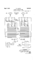
- Fig. 1 shows the circuit of the combination selector and connector together with enough of the other circuits to enable its operation to be explained and understood.
- Fig. 2 is a schematic diagram of the trunking arrangement.
- FIG. 2 This is a schematic drawing and is intended to illustrate a private automatic exchange system having a capacity of two hundred lines.
- the system comprises two one hundred line units. Considering first the left hand unit the subscribers lines shown at the upper left hand corner of the sheet "are provided at the exchange with individual rotary line switches ,which are indicated in the customary manner.
- the combination selector connectors are switches of the well known Strowger vertical and rotary type, and have the usual mechanical construction. They have, however. two complete sets of banks and wipers. The upper set of banks are the selector banks while the lower set of banks are the connector banks. Each set of banks is indicated by ten heavy lines corresponding to the ten levels.
- the selector levels are used for trunking to an operators position, to the main exchange, and to another unit, or units, if there be more than two units in the system. In the connector levels are terminated the normal conductors of the subscribers lines.
- these lines 5 are numbered from 301 to 399 and the left hand unit may therefore be called the three hundred unit.
- the other unit shown at the right is exactly like the unit just described.
- Local lines 401 to 499 terminate in the right hand unit and it will therefore be referred to as the-four hundred unit.
- the selector connector in use is raised-to the-third level, whereupon it is at once released automatically and its character is changed from that of a selector to that of a connector.
- the calling subscriber may then call the remaining two digits O5 in the desired number and the selector connector is reoperated in the well known manner to complete the connection. Connections which are local to the four hundred unit are established in the same manner except that the first digit in each unit corresponds to the critical level of to be called in each case is the digit 4, as the fourth level is the critical level in the four hundred group.
- the process of establishing inter-unit connections may now be considered.
- two groups of trunk lines are necessarily provided.
- the trunk lines of one group extend from the fourth selec or level in the three hundred unit to the combination selector connectors of the four hundred unit, while the trunk lines of the other group extend from the third selector level in the four hundred unit to the combination selector connectors of the three hundred unit.
- the combination selector connectors of the four hundred unit are accessible to the line switches of the same unit .and also to the selector connectors of the three hundred unit, when the latter switches operate as selectors; while the selector connectors of the three hundred unit are similarly made accessible to the associated line switches and also to the selector connectors of the four hundred unit.
- selector connectors are accessible to line switches and other selector connectors, the operation of one of these switches is not the same when the switch is seized from the two different classes of switches.
- a selector connector of the type herein disclosed is normally adapted to operate as a selector and when seized by a line switch its character is not changed in the least. But when seized by another selector connector, the character of the seized switch is at once changed to that of a connector.
- the selector connector in which the trunk terminates is instantly changed from a selector to a connector, for it has been seized by another selector connector.
- the calling subscriber may now call the remaining two digits in the number, and the selector connector in the four hundred unit which has been taken for use is operated as a connector to complete the desired connection. Connections in the reverse direction or from the four hundred unit to the three hundred unit are established in the same manner.
- selector levels' may be used for calling an attendant operator or for reaching trunk lines which extend to the main exchange. This is shown in the drawings, which show a group of trunk lines extending from the first selector level to an operators position,
- Fig. 1 shows a calling station A and the individual line switch 0 which is associated therewith.
- One of the combination selector connectors to which the line switch has access is also shown and is indicated by the reference character D.
- the two sets of wipers are shown, the upper set being the selector wipers and the lower set being the connector wipers.
- the first contact sets in four selector levels are also shown, likewise the first contact sets in four connector levels.
- a local line leading from the third connector level is shown extending to the called substation A. Trunk line conductors are also shown leading off from the first, second, and fourth selector levels. All the apparatus shown is assumed to be part of the three hundred unit.
- the subscriber at substation A desires to obtain connection with a subscriber at substation A
- a circuit is completed over the line conductors 11 and 12 in the usual manner, and the line relay 15 of the line switch C is energized.
- the line relay l5 closes a circuit at its armature 20 which includes the switching relay 14 and the stepping magnet 16 in series, and at its armature 21 connects the test wiper 22 to the above circuit at a point midway between the said switching relay and magnet.
- the operation now depends upon whether the trunk line with which the line switch wipers are associated is busy or is not busy.
- the switching relay 14 will be short circuited, and the stepping magnet 16, being supplied with direct ground by way of the said test wiper, will operate in the manner of a buzzer to advance the line switch wipers step by step in search'of an idle trunk line. It may be assumed, however, that when the call is initiated the wipers of the line switch are in engagement with bank contacts associated with the trunk line extending to the combination selector connector D, as shown in the drawings, and it may be assumed furthermore that this trunk line is idle. Under these circumstances, when the line relay 15 is energized the switching relay 14 is energized immediately afterwards and no rotation of the switch will take place.
- the switching relay 14 disconnects the line conductors 11 and 12 from the winding of the line relay and from ground, respectively, and extends these line conductors by way of wipers 21 and 23, bank contacts 24 and 26, conductors 27 and 29, and armatures 66 and 70 and their resting contacts, to the windings of the double wound line relay 51 of the selector connector D.
- the line relay 51 is energized over the line circuit and at opposite the third connector level.
- release trunk conductor 202 is one of the conductors of the trunk line comprising conductors 201, 202, and 203, which trunk line comes from the fourth selector level in the four hundred unit.
- the grounding of conductor 202 of course renders the combination selector connector D busy to the selector connectors in the four hundred unit.
- relay 52 connects the release trunk conductors 202 and 28 together and thus places a ground potential upon the latter conductor also.
- a ground potential is also extended by way of private normal conductor 13 to multiple test contact in the connector banks of the three hundred unit whereby the line of substation A is made busy in the usual manner.
- the calling subscriber may now operate his calling device in accordance with the first digit in the desired number. Since'the called station is also in the three hundred unit this digit will be the digit 3.
- the line relay 51 is momentarily deenergized three times.
- the line relay transmits a current impulse to the vertical magnet 60 over the following circuit; ground at G armature 68 and its resting contact, armature '71 and its resting contact, armature 72 and its working contact, off normal springs 63 and 65, Winding of the slow acting series relay 53, and the winding of the vertical magnet 60 to battery.
- the above is the circuit over which the first impulse is transmitted.
- the third level is the critical level for the three hundred unit and when the shaft of the selector connector D. is raised to this level the shaft controlled springs 40, 41, and 42 are shifted, that is, the
- spring 41 is separated from spring 40 and is brought into engagement with spring 42.
- These springs may be controlled by any suitable cam device on the shaft, but are preferably mounted just above the upper end of the shaft in such a position that they may be actuated by the circular cup spring casing which is mounted on top of the shaft.
- the slow acting relay 53 is energized in series with the vertical magnet and retains its armatures attracted as long as the vertical magnet is receiving impulses.
- relay 53 is deenergized and a circuit for the release magnet 62, is completed as follows: from grounded armature 75 of relay 52, by Way of the working contact of the said armature, normally closed contact springs controlled by armature 99, shaft springs 41 and 42, armature 95 and its resting contact, upper pair of off normal springs, and the winding of the release magnet 62 to battery.
- the release magnet 62 becomes energized and restores the switch D to normal position in the usual manner.
- the release magnet 62 closes a circuit for the relay 59 in an obvious manner and it follows therefore that at the same time that the switch is released, the relay 59 will be operated.
- relay 59 Uponenergizing, relay 59 establishes a locking circuit for itself at its armature 94, disconnects the selectortest wiper 102 at armature 91, connects up the connector test wiper 105 at armature 92, prepares a directive control circuit for the rotary magnet 61 at armature 93, breaks the circuit by which the release magnet 62 was just operated-at armature 95, and at armature 96 breaks the circuit of the stepping relay 54.
- Relay 59 is the relay whose operation changes the character of the combination selector connector Dgfrom that of a selector to that of a connector.
- the calling subscriber may now operate his calling device in accordance with the next digit in the required number which will also be the digit 3, inasmuch as the line of substation A terminates in the third conector level.
- the vertical magnet 60 is operated as before under control of the line relay 51 and the two sets of wipers are raised to the third level.
- the slow acting series relay 53 is energized in series with the vertical magnet and retains its armature attracted while the vertical magnet isoperating. At the end of the vertical movement of the switch this relay falls back and at its armature '73 transfers the operating circuit to the rotary magnet 61.
- the line relay 51 responds as before and transmits a series of impulses to the rotary magnet 61 over the following circuit: ground at G armature 68 and its resting contact, armature 71 and its resting contact, armature 72 and its working contact, off normal springs 63 and 64, armature 73 and its resting contact, armature 79 and its resting contact, winding of the slow acting series relay 57, armature 89 and its resting contact, armature 93 and its working contact, and the winding of the rotary magnet 61 to battery.
- the connector wipers 104, 105, and 106 are rotated step by step until they come to rest in engagement with the par- ;ticular set of bank contacts which is associated with the line of substation A. Since this line At the end of the vertical terminates in the first set of bank contacts in the third level, as a matter of fact the wipers will take only one step and will come to rest in engagement with bank contacts 107, 108, and 109, respectively.
- the slow acting series relay 5'! is energized in series with the rotary magnet 61 and at its armature 84 connects the connector test wiper 105 to the upper winding of the combination test and back bridge relay 55.
- relay 57 closes a shunt around the contact at armature 79 of the said relay by means of its armature 85 thereby guarding against the opening of the rotary magnet circuit in case relay 55 should be energized by the test wiper 105 passing over grounded test contacts.
- test wiper 105 comes to rest in engagement with test contact 108 it will find no ground potential and the test relay 55 will not be energized.
- relay 14' is operated only about half way due to a mechanical interlocking device controlled by line relay 15', and the line conductors are not connected through to the line switch wipers.
- the switching relay 58 When the switching relay 58 is energized it establishes a locking circuit for itself at its armature 87, connects ground to the test wiper 105 at its armature 88, opens the rotary magnet circuit at its armature 89, and at its armatures 86 and 90 connects up the connector line wipers 104 and 106.
- ringing current from the generator Gen is intermittently projected out over the called line in the usual manner to operate the bridgedringer at the substation.
- the return path for the ringing current includes the lower winding of the ring out oif relay 56, and when the called subscriber responds by removing his, receiver the said relay is energized and establishes a locking circuit for itself at its armature 82.
- the ring out olf relay' also breaks the ringing circuit by means of its armatures 81 and 83 and at the working-contacts of these armatures finally completes the talking circuit.
- the operation of the two armatures mentioned effects the disconnection of the busy signalling machine and the conductor over which relay 55 is energized when used as a test relay.
- the talking circuit having been completed the calling and calledv subscribers may converse as desired.
- the transmitter at substation A is supplied with talking battery through the windings of the double wound line relay 51. while the transmitter at substation A is supplied with talking battery through the windings of the double wound combination back bridge and test relay 55.
- the voice currents take the path shown in heavy lines which is of the usual character and will be understood without further explanation.
- the vertical magnet 60 When this digit is called the vertical magnet 60 is operated under control of the line relay 51 to raise the switch wipers to the fourth level.
- the slow acting series relay 53 is energized in series with the vertical magnet and retains its armature attracted throughout the vertical operation of the switch. At the first upward movement of the switch shaft this relay closes a circuit for the stepping relay 54 which is energized and locked up as previously described.
- the shaft spring 41 is shifted on the third vertical step, this operation is of no effect because at this time the relay 53 is in energized position, and when the shaft and wipers come to rest at the fourth level the shaft spring 42 will return to its normal position. This spring is so adjusted in position that it is operated only on the third level.
- the rotary magnet breaks its interrupter contact and thus opens a locking circuit of the stepping relay 54, which accordingly deenergizes and breaks the circuit of the rotary magnet, and the rotary magnet then deenergizes also and again closes its interrupter contact.
- the operation now depends upon whether the first trunk line in the fourth level is or is not busy. If this trunk line is busy the selector test wiper 102 will find a ground potential upon test contact 121 and a circuit will be completed for again energizing the stepping relay 54.
- This circuit may readily be traced from the grounded test contact 121 by way of the test wiper 102, armature 91 and its resting contact, armature 67 and its resting contact, interrupter contact of the rotary magnet 61, off normal springs 97 and 98, resting contact of armature 96 and the said armature, and the winding of relay 54 to battery.
- the stepping relay 54 is therefore again'energized in case the first trunk line is busy and again closes the circuit of the rotary magnet, and the operations just described are repeated.
- I may assume that in the present case the first trunk line in the fourth level is idle when the selector connector D begins its trunk hunting movement.
- the switching relay 50 which has remained short circuited hereto, is energized over a circuit which extends from the grounded release trunk 202 by way of the winding of the said switching relay 50, interrupter contact of the rotary magnet 61, off normal springs 97 and 98, resting contact of armature 96 and the said armature, and the winding of the stepping magnet 54 to battery.
- the switching relay 50 has such a high resistance that the relay 54 does not now operate.
- Relay 50 is energized, however, and at its armature 6'7 connects the release trunk conductor 202 to the selector test wiper 102, disconnects ground from the line relay by means of armature 68, opens another circuit which will be described shortly, at its armature 69, and at armatures 66 and 70 disconnects the incoming trunk conductors 27 and 29 from the windings of the line relay 50 and extends them by way of the working contacts of these armatures, selector line wipers 101 and 103, bank contacts 120 and 122, and trunk conductors 123 and 125 to the line relay of the combination selector connector in which these conductors terminate in the four hundred unit.
- the conductors 123, 124 and 125 constitute a trunk line which is one of the trunk lines extending from the three hundred unit to the four hundred unit and terminating in the latter unit in one of the combination selector connectors, as explained fully in the description of trunking between units.
- the trunk line comprising conductors 201, 202, and 203 is a trunk line coming from the third selector level in the four hundred unit and terminates in the selector connector D as shown.
- the two line conductors 201 and 203 are multipled with the line conductors 27 and 29 of the trunk line coming from the line switchboard.
- Conductor 202 is the release trunk conductor and is connected as shown, being kept separate from the release trunk conductor 28 of the trunk line coming from the line switchboard as long as the selector connector D is idle.
- the switching relay 50 pulls up and connects the grounded release trunk conductor 202 with the test wiper 102 a ground potential is placed upon the release trunk conductor 124 extending to the selector connector in the four hundred unit. By this operation a circuit is completed for a relay in such selector connector which corresponds to the relay 59 in the selector connector D.
- the circuit may be traced as follows: from the test contact in which the conductor 202 terminates in the four hundred group by way of the said test conductor, normally closed contact springs controlled by armature '75, armature 69 and its resting contact, and the winding of relay 59 to battery.
- the efiect of the closure of the corresponding circuit in the selector connector in the four hundred unit during the establishment of the present connection is to energize the relay in such switch corresponding to relay 59 in the selector connector D and the character of the switch in the four hundred unit is at once changed to,that of a connector.
- the subscriber at substation A has selected an idle trunk line extending to the four hundred unit and the selector connector in which this trunk line terminates has been changed automatically from a selector to a connector.
- the last two digits in the desired number may now be called and the selector connector in the four hundred unit responds and the connection to the desired line is completed in precisely the same manner as when the selector connector D was being operated as a connector to complete the connection to the line of substation A. Since this operation has been fully described it will be unnecessary to consider the same any further.
- an essential feature of the present system is the arrangement whereby the circuit of any selector connector is instantly changed when the switch is seized over a trunk line coming from a selector level in another unit, and whereby the circuit of such selector connector is not changed or altered in case it is seized over a trunk line coming from the associated line switchboard.
- This is accomplished, as will be understood by this time, by the provision of two separate release trunk conductors extending to each selector connector.
- the selector connector D one of the release trunk conductors, the one coming from the selector level, normally extends through to the relay 59, which has the function of changing the character of the switch from that of a selector to that of a connector.
- the other release trunk conductor 28 is normally open, and is not connected up until the slow acting release relay 52 operates. But the release relay 52 also opens the circuit of relay 59 at the same time or a little before the trunk line coming from the line switchboard is connected up, and it follows therefore that when the switch is seized by one of the line switches the relay 59 will not be operated.
- each such trunk line is provided with means for grounding the release trunk conductor after the trunk line is seized in order to provide a holding circuit for the selector connector in use, which of course operates as a selector switch in the manner previously explained.
- the repeaters in the main exchange trunks are of course provided with such means in accordance with the usual practice, and the provision of similar means in the trunk lines extending to an operator is of common occurence. It is thought, therefore, that further consideration of these points is unnecessary.
- a combination selector and connector switch for use in connecting subscribers lines, separate selector and connector wipers and banks in said switch, means for operating said switch in accordance with a digit in a called number, and means for changing the character of said switch so that it can be operated either as a selector or a connector depending on the digit called.
- an automatic switch having duplicate sets of wipers, trunk lines accessible to one set of wipers, subscribers lines accessible to the other set of wipers, means for extending a calling line to said switch, and means for operating said switch as a selector to connect with an idle trunk line, or for operating said switch as a connector to connect with a desired subscribers line, at the option of the calling subscriber.
- a combination selector and connector for use in connecting subscribers lines, the said switch being normally adapted for directive primary and automatic secondary movement to operate as a selector switch, and means operated responsive to a primary movement of predetermined extent for temporarily changing the character of said switch to enable the same to operate in two directive movements as a connector switch.
- an automatic switch normally operable as a selector to select a group of said trunk lines and adapted to automatically select an idle trunk line in the selected group, means effective when said switch is operated in accordance with a digit in the number of one of said subscribers lines for changing the character of said switch to that of a connector, and means for then directively operating said switch to connect with a desired one of said subscribers lines.
- an automatic switch having directive primary movement, and automatic secondary or trunk selecting movement, and means operated automatically by a primary movement of predetermined extent for changing the character of said switch to eliminate the trunk selecting movement and adapt the switch to complete directive control.
- a combination-selector and connector normally operative as a selector and having directive primary and automatic secondary movements, said switch being also capable of acting as a connector with two directive movements, and means responsive to a primary movement of predetermined extent when the switch is operated as a selector for changing the character of said switch to that of a connector.
- a third switch accessible to switches in both said classes, said third switch having an automatic trunk selecting movement, means operated automatically when said third switch is seized by a switch in a particular one of said classes for changing the character of said third switch to eliminate the trunk selecting movement and adapt the switch to directive control, and means for similarly changing the character of said third switch under the directive control of a calling subscriber when said third switch is seized by a switch in the other class.
- switches of one class having automatic trunk selecting movement only and the switches of the other class being directively controlled
- a third switch accessible to the switches in both said classes and having definite normal capable of acting'as a connector withtwo direc-- operating characteristics
- directively controlled means for changing the character of said third switch when the same is seized by a switch in the trunk selecting class.
- a third switch accessible to the switches in both said classes and having two sets of wipers one of which is normally connected. means for automatically switching to the other set of wipers .when said" third switch is seized by a switch in a particular one of said classes, and subscriber controlled means for switching wipers when said third switch is seized by a switch in the other one of said classes.
- each combination switch is accessible to a plurality of said line switches and also to a plurality of the other combination switches, mechanism operable responsive to the calling of a digit in-a called number for changing one of said combination switches to a connector switch when the same is seized by one of said line switches, and means for operating said mechanism automatically when the same switch is seized by another one of said combination switches.
- an automatic switch having a primary magnet and an automatically operated secondary magnet, means for directively operating said primary magnet, and means responsive to aparticular primary operation for shifting the secondary magnet from automatic to directive control.
- a combination selector and connector switch normally operative as a selector with directive primary and automatic secondary movements, said switch being also tive movements, means for transmitting series of impulses to said switch, and mechanism in said switch responsive only to a particularseries of impulses for changing its character from that of a selector to that of a connector.
- a combination selector and connector switch normally operative as a selector with directive primary and automatic secondary movements, said switch being also capable of acting as a connector with two directive movements, a trunk line terminating in said switch including a conductor separate from the talking circuit, and means in said switch controlled over said conductor when the switch is taken for use via said trunk line for changing the character of the switch from that of a selector to that of a connector.
- a combination selector and connector switch normally operative as a selector with directive primary and automatic secondary movements, said switch being also capable of acting as a connector with two directive movements, a trunk line terminating in said switch and including a release trunk conductor, a second switch, and means in said first switch controlled by said second switch over said release conductor for changing the character of said first switch from that of a selector to that of a connector.
Landscapes
- Physics & Mathematics (AREA)
- Astronomy & Astrophysics (AREA)
- General Physics & Mathematics (AREA)
- Engineering & Computer Science (AREA)
- Computer Networks & Wireless Communication (AREA)
- Structure Of Telephone Exchanges (AREA)
Description
Sept. 5, 1933. c. E. LOMAX 1,925,254
AUTOMATIC TELEPHONE SYSTEM Original Filed Sept. 3 1920 2 Sheets-Sheet l 1UUEUZUI' E151: ncaELmmsx Patented Sept. 5, 1933 UNITED STATES PATENT OFFICE f AUTOMATIC TELEPHONE SYSTEM of Delaware Application September 3, 1920. Serial No. 407,996
26 Claims.
My invention relates in general to automatic telephone systems and is particularly well adapted for use in private automatic exchanges of thetype commonly used in large factories or mercantile establishments, although no doubt certain features of the invention will be of utility in ordinary public exchanges. However, as stated, the invention is especially applicable to private automatic exchanges and this is the embodiment of the invention that will be shown and described herein.
Broadly speaking, the system of the present invention is a private automatic exchange system which employs the same number of different classes of switches as the ordinary 100 line system in common use, these switches being individual line switches and connector switches, but which is capable of serving the full one hundred lines under all circumstances and which may be increased in capacity up to any reasonable extent (700 or 800 lines), by merely adding other units and without inserting first selectors or adding any other class of switches. I accomplish these results by the use of a final connector which is in reality a combination selector and connector, capable of operating at one time as a connector on the full ten levels and at another time as a selector on nine levels. I have provided also a novel trunking system adapted to make use of the combination selector and connector which provides for a uniform numbering scheme and includes circuit arrangements which provide for automatically changing the character of the combination switches when they are required to act as connector switches instead of as selector switches. These features and others not now specifically mentioned will be described fully hereinafter, reference being had to the accompanying drawings.
Referring now to the drawings, Fig. 1 shows the circuit of the combination selector and connector together with enough of the other circuits to enable its operation to be explained and understood. Fig. 2 is a schematic diagram of the trunking arrangement.
The general layout of the system will first be explained by means of the trunking diagram Fig. 2. This is a schematic drawing and is intended to illustrate a private automatic exchange system having a capacity of two hundred lines. The system comprises two one hundred line units. Considering first the left hand unit the subscribers lines shown at the upper left hand corner of the sheet "are provided at the exchange with individual rotary line switches ,which are indicated in the customary manner.
These rotary line switches have common access to a group of combination selector connectors which are indicated by squares immediately below the line switches. The combination selector connectors are switches of the well known Strowger vertical and rotary type, and have the usual mechanical construction. They have, however. two complete sets of banks and wipers. The upper set of banks are the selector banks while the lower set of banks are the connector banks. Each set of banks is indicated by ten heavy lines corresponding to the ten levels. The selector levels are used for trunking to an operators position, to the main exchange, and to another unit, or units, if there be more than two units in the system. In the connector levels are terminated the normal conductors of the subscribers lines. As shown in the drawings these lines 5 are numbered from 301 to 399 and the left hand unit may therefore be called the three hundred unit. The other unit shown at the right is exactly like the unit just described. Local lines 401 to 499 terminate in the right hand unit and it will therefore be referred to as the-four hundred unit.
The process of setting up connections may now be briefly considered. Suppose first, that a subscriber in the three hundred unit desires to connect with another subscriber in the same unit. When the receiver is removed at the calling station the rotary line switch associated therewith operates to select an idle combination selector connector in the usual manner. The combination selector connectors are normally adapted to operate as selectors and since no selector operation is required in the connection now to be established the next thing to be done is to change the character of the switch taken for use to that of a connector. Thisv is accomplished by calling the digit which corresponds to what may be termed the critical level, which in the case of the three hundred unit is the third level. When the digit 3 is called therefore the selector connector in use is raised-to the-third level, whereupon it is at once released automatically and its character is changed from that of a selector to that of a connector. The calling subscriber may then call the remaining two digits O5 in the desired number and the selector connector is reoperated in the well known manner to complete the connection. Connections which are local to the four hundred unit are established in the same manner except that the first digit in each unit corresponds to the critical level of to be called in each case is the digit 4, as the fourth level is the critical level in the four hundred group.
The process of establishing inter-unit connections may now be considered. In order to handle these connections two groups of trunk lines are necessarily provided. The trunk lines of one group extend from the fourth selec or level in the three hundred unit to the combination selector connectors of the four hundred unit, while the trunk lines of the other group extend from the third selector level in the four hundred unit to the combination selector connectors of the three hundred unit. Thus the combination selector connectors of the four hundred unit are accessible to the line switches of the same unit .and also to the selector connectors of the three hundred unit, when the latter switches operate as selectors; while the selector connectors of the three hundred unit are similarly made accessible to the associated line switches and also to the selector connectors of the four hundred unit. It will be noted that the inter-unit trunking level the other unit, and it is this arrangement which preserves the uniform numbering scheme. There is one other thing which requires to be mentioned now before proceeding further. Although the selector connectors are accessible to line switches and other selector connectors, the operation of one of these switches is not the same when the switch is seized from the two different classes of switches. As stated, a selector connector of the type herein disclosed is normally adapted to operate as a selector and when seized by a line switch its character is not changed in the least. But when seized by another selector connector, the character of the seized switch is at once changed to that of a connector.
With this explanation the process of establishing an inter-unit connection, originating in the three hundred unit, for example, will readily be understood. When the receiver is removed at the calling station the rotary line switch associated therewith operates to select an idle selector connector as before, and the switch taken for use is then raised to the fourth level by calling the digit 4, which is the first digit in the numbers of all lines terminating in the four hundred unit. Since the selector connector in use has been seized by a line switch and since it has been raised to a level other than the third level, or the critical level, the character of the switch is not changed and it operates as a selector to select an idle trunk line extending to the four hundred unit. When connection to the trunk line is completed the selector connector in which the trunk terminates is instantly changed from a selector to a connector, for it has been seized by another selector connector. -The calling subscriber may now call the remaining two digits in the number, and the selector connector in the four hundred unit which has been taken for use is operated as a connector to complete the desired connection. Connections in the reverse direction or from the four hundred unit to the three hundred unit are established in the same manner.
As stated before, certain of the selector levels' may be used for calling an attendant operator or for reaching trunk lines which extend to the main exchange. This is shown in the drawings, which show a group of trunk lines extending from the first selector level to an operators position,
and another group of trunk. lines extending from r the second level by way of repeaters to a main exchange, which may be of any well known type and therefore is not shown. The first and second levels are of course multiplied between units. It A dred lines.
Having given a general description of the trunking arrangement and the system as a whole, reference will now be made to Fig. 1 for the pur-. pose of explaining more in detail the circuits and operation of the combination selector connector. Fig. 1 shows a calling station A and the individual line switch 0 which is associated therewith. One of the combination selector connectors to which the line switch has access is also shown and is indicated by the reference character D. At the right the two sets of wipers are shown, the upper set being the selector wipers and the lower set being the connector wipers. The first contact sets in four selector levels are also shown, likewise the first contact sets in four connector levels. A local line leading from the third connector level is shown extending to the called substation A. Trunk line conductors are also shown leading off from the first, second, and fourth selector levels. All the apparatus shown is assumed to be part of the three hundred unit.
Assuming now that the subscriber at substation A desires to obtain connection with a subscriber at substation A, when the receiver is removed at the calling station a circuit is completed over the line conductors 11 and 12 in the usual manner, and the line relay 15 of the line switch C is energized. Upon energizing, the line relay l5 closes a circuit at its armature 20 which includes the switching relay 14 and the stepping magnet 16 in series, and at its armature 21 connects the test wiper 22 to the above circuit at a point midway between the said switching relay and magnet. The operation now depends upon whether the trunk line with which the line switch wipers are associated is busy or is not busy. If this trunk line is busy the test contact with which the test wiper 22 is in engagement will have a ground potential upon it, the switching relay 14 will be short circuited, and the stepping magnet 16, being supplied with direct ground by way of the said test wiper, will operate in the manner of a buzzer to advance the line switch wipers step by step in search'of an idle trunk line. It may be assumed, however, that when the call is initiated the wipers of the line switch are in engagement with bank contacts associated with the trunk line extending to the combination selector connector D, as shown in the drawings, and it may be assumed furthermore that this trunk line is idle. Under these circumstances, when the line relay 15 is energized the switching relay 14 is energized immediately afterwards and no rotation of the switch will take place. By means of armatures 1'7 and 19 the switching relay 14 disconnects the line conductors 11 and 12 from the winding of the line relay and from ground, respectively, and extends these line conductors by way of wipers 21 and 23, bank contacts 24 and 26, conductors 27 and 29, and armatures 66 and 70 and their resting contacts, to the windings of the double wound line relay 51 of the selector connector D.
When the calling line is extended to the switch D in the manner described above. the line relay 51 is energized over the line circuit and at opposite the third connector level.
its armature '71 closes a circuit for the slow acting release relay 52. Upon energizing, relay 52 prepares a circuit for the vertical magnet 60 at armature 72, and at armature '75 connects ground to the releasetrunk conductor 202. Release trunk conductor 202 is one of the conductors of the trunk line comprising conductors 201, 202, and 203, which trunk line comes from the fourth selector level in the four hundred unit. The grounding of conductor 202 of course renders the combination selector connector D busy to the selector connectors in the four hundred unit. At its armature '74, relay 52 connects the release trunk conductors 202 and 28 together and thus places a ground potential upon the latter conductor also. By this operation a holding circuit is established which extends by way of conductor 28, test contact 25, test wiper 22, armature 18 and its working contact, winding of the switching relay 14, and the winding of the stepping magnet 16 to battery. This circuit serves to maintain the switching 'relay 14 energized throughout the connection,
and is established before the slow acting line re lay 15 has had time to fall back. A ground potential is also extended by way of private normal conductor 13 to multiple test contact in the connector banks of the three hundred unit whereby the line of substation A is made busy in the usual manner.
The calling subscriber may now operate his calling device in accordance with the first digit in the desired number. Since'the called station is also in the three hundred unit this digit will be the digit 3. By the operation of the calling device a series of three interruptions is produced in the line circuit and the line relay 51 is momentarily deenergized three times. At each deenergization the line relay transmits a current impulse to the vertical magnet 60 over the following circuit; ground at G armature 68 and its resting contact, armature '71 and its resting contact, armature 72 and its working contact, off normal springs 63 and 65, Winding of the slow acting series relay 53, and the winding of the vertical magnet 60 to battery. The above is the circuit over which the first impulse is transmitted. On the first vertical step the off normal springs are shifted and the circuit is altered slightly so that it includes off normal springs 63 and 64 and armature '73 of relay 53 and its working contact, relay 53 being now in operated position. When ofi normal springs 9'7 and 98 are closed on the first vertical step a circuit is completed for the stepping relay 54 as follows: from the grounded armature of which were transmitted to the vertical magnet 60 operate the said magnet to raise the switch shaft step by step until the selector wipers 10l103,
inclusive, stand opposite the third selector level,-
and the connector wiper 104--106, inclusive, stand The third level is the critical level for the three hundred unit and when the shaft of the selector connector D. is raised to this level the shaft controlled springs 40, 41, and 42 are shifted, that is, the
spring 41 is separated from spring 40 and is brought into engagement with spring 42. These springs may be controlled by any suitable cam device on the shaft, but are preferably mounted just above the upper end of the shaft in such a position that they may be actuated by the circular cup spring casing which is mounted on top of the shaft. As before stated, the slow acting relay 53 is energized in series with the vertical magnet and retains its armatures attracted as long as the vertical magnet is receiving impulses. movement of the switch, relay 53 is deenergized and a circuit for the release magnet 62, is completed as follows: from grounded armature 75 of relay 52, by Way of the working contact of the said armature, normally closed contact springs controlled by armature 99, shaft springs 41 and 42, armature 95 and its resting contact, upper pair of off normal springs, and the winding of the release magnet 62 to battery. Upon the closure of this circuit the release magnet 62 becomes energized and restores the switch D to normal position in the usual manner. In operating, the release magnet 62 closes a circuit for the relay 59 in an obvious manner and it follows therefore that at the same time that the switch is released, the relay 59 will be operated. Uponenergizing, relay 59 establishes a locking circuit for itself at its armature 94, disconnects the selectortest wiper 102 at armature 91, connects up the connector test wiper 105 at armature 92, prepares a directive control circuit for the rotary magnet 61 at armature 93, breaks the circuit by which the release magnet 62 was just operated-at armature 95, and at armature 96 breaks the circuit of the stepping relay 54. Relay 59, it will be noted, is the relay whose operation changes the character of the combination selector connector Dgfrom that of a selector to that of a connector.
The calling subscriber may now operate his calling device in accordance with the next digit in the required number which will also be the digit 3, inasmuch as the line of substation A terminates in the third conector level. When the calling device is operated the vertical magnet 60 is operated as before under control of the line relay 51 and the two sets of wipers are raised to the third level. The slow acting series relay 53 is energized in series with the vertical magnet and retains its armature attracted while the vertical magnet isoperating. At the end of the vertical movement of the switch this relay falls back and at its armature '73 transfers the operating circuit to the rotary magnet 61.
The calling subscriber may now operate his calling device for the next and final digit in the number. When this digit is called the line relay 51 responds as before and transmits a series of impulses to the rotary magnet 61 over the following circuit: ground at G armature 68 and its resting contact, armature 71 and its resting contact, armature 72 and its working contact, off normal springs 63 and 64, armature 73 and its resting contact, armature 79 and its resting contact, winding of the slow acting series relay 57, armature 89 and its resting contact, armature 93 and its working contact, and the winding of the rotary magnet 61 to battery. By the operation of the rotary magnet the connector wipers 104, 105, and 106 are rotated step by step until they come to rest in engagement with the par- ;ticular set of bank contacts which is associated with the line of substation A. Since this line At the end of the vertical terminates in the first set of bank contacts in the third level, as a matter of fact the wipers will take only one step and will come to rest in engagement with bank contacts 107, 108, and 109, respectively. The slow acting series relay 5'! is energized in series with the rotary magnet 61 and at its armature 84 connects the connector test wiper 105 to the upper winding of the combination test and back bridge relay 55. In addition, relay 57 closes a shunt around the contact at armature 79 of the said relay by means of its armature 85 thereby guarding against the opening of the rotary magnet circuit in case relay 55 should be energized by the test wiper 105 passing over grounded test contacts.
It will be assumed now that the line of substation A is busy when called as just described. In
. such case, when the test wiper 105 comes to rest in engagement with .test contact 108 it will find a ground potential thereon and the combination back bridge and test relay 55 will; be energized. When the slow acting relay 57 deenergizes an instant later a locking circuit is completed for' relay 55 which includes-its armature 78 and the normally closed contact springs controlled by armature 84 of relay 57. In its energized position relay 55 also opens the rotary magnet circuit at its armature 79, and at its armature 80 connects a lead from the busy signalling machine to the lower heavy talking conductor. By the latter operation the calling subscriber is given a busy signal, and being advised thereby that the called line is for the time being inaccessible, he will replace his receiver.
Having described the operations which take place when the called line isbusy it will now be' assumed that the line is idle when called. Under these circumstances, when the test wiper 105 comes to rest in engagement with test contact 108 it will find no ground potential and the test relay 55 will not be energized. Then when the slow acting relay 57 deenergizes a circuit is completed for the switching relay 58 as follows: from the grounded release trunk conductor 202, by way of armature 78 and its resting contact, lower winding of relay 58, resting contact of armature 84 and the said armature, armature 92 and its working contact, test wiper 105, test contact 108, conductor 111, Winding of the switching relay 14' of line switch C, and the winding of the stepping magnet 16 to battery. Upon the closure of the above circuit relays 58 and 14' are energized in series and the latter relay is operated to disconnect the line of substation A from its normal battery and ground connections in the line switch. It is noted that relay 14' is operated only about half way due to a mechanical interlocking device controlled by line relay 15', and the line conductors are not connected through to the line switch wipers. At the selector connector D, when the switching relay 58 is energized it establishes a locking circuit for itself at its armature 87, connects ground to the test wiper 105 at its armature 88, opens the rotary magnet circuit at its armature 89, and at its armatures 86 and 90 connects up the connector line wipers 104 and 106.
The connection having been completed, ringing current from the generator Gen is intermittently projected out over the called line in the usual manner to operate the bridgedringer at the substation. It will be noticed that the return path for the ringing current includes the lower winding of the ring out oif relay 56, and when the called subscriber responds by removing his, receiver the said relay is energized and establishes a locking circuit for itself at its armature 82. The ring out olf relay' also breaks the ringing circuit by means of its armatures 81 and 83 and at the working-contacts of these armatures finally completes the talking circuit. It may be noted also that the operation of the two armatures mentioned effects the disconnection of the busy signalling machine and the conductor over which relay 55 is energized when used as a test relay.
The talking circuit having been completed the calling and calledv subscribersmay converse as desired. The transmitter at substation A is supplied with talking battery through the windings of the double wound line relay 51. while the transmitter at substation A is supplied with talking battery through the windings of the double wound combination back bridge and test relay 55. The voice currents take the path shown in heavy lines which is of the usual character and will be understood without further explanation.
When the conversation .is finishedboth subscribers will hang up their receivers. receiver is replaced at substation A the line and release relays 51 and 52 are deenergized and a circuit is completed for the release magnet 62 which accordingly operates to restore the selector connector to normal position. Relay 52 also disconnects ground from the two release trunk conductors 28 and 202 and as a result the relays which were locked up in the selector connector switch are permitted to deenergize. The rem val of ground from release trunk conductor 28 permits the switching relay 14 of the line switch, C to fall back and the line switch is therefore restored to normal condition also.
Hav'ing described the process of setting up a connection in the case where both the calling and called subscribers are in the same unit, I will now explain briefly how a connection is established when the calling subscriber is located in the three hundred unit and the called subscriber in the four hundred unit. Assuming that the calling subscriber is the subscriber at substation A, when the receiver is removed the line switch C is operated as before to select'an idle trunk line which we may assume to be the trunk When the line extending to the combination selector connector D. The line and release relays 51 and 52 of the selector connector are now energized with the usual results. The calling subscriber may now operate his calling device in accordance with the first digit in the desired number, which in the present case will be the digit 4. When this digit is called the vertical magnet 60 is operated under control of the line relay 51 to raise the switch wipers to the fourth level. The slow acting series relay 53 is energized in series with the vertical magnet and retains its armature attracted throughout the vertical operation of the switch. At the first upward movement of the switch shaft this relay closes a circuit for the stepping relay 54 which is energized and locked up as previously described. Although the shaft spring 41 is shifted on the third vertical step, this operation is of no effect because at this time the relay 53 is in energized position, and when the shaft and wipers come to rest at the fourth level the shaft spring 42 will return to its normal position. This spring is so adjusted in position that it is operated only on the third level. Now when the slow acting relay 53 deenergizes at the end of the vertical movement of the switch a circuit is completed for the rotary magnet 61 as follows: from grounded armature 75, by way of the said armature and its'working contact, normally closed contact springs controlled by armature 99, shaft springs 41 and 40, armature 76 and its working contact, and the winding of the rotary magnet 61 to battery. By the closure of the above circuit the rotary magnet 61 is energized and operates to rotate the switch wipers into engagement with the first set of bank contacts in the fourth level. In operating, the rotary magnet breaks its interrupter contact and thus opens a locking circuit of the stepping relay 54, which accordingly deenergizes and breaks the circuit of the rotary magnet, and the rotary magnet then deenergizes also and again closes its interrupter contact. The operation now depends upon whether the first trunk line in the fourth level is or is not busy. If this trunk line is busy the selector test wiper 102 will find a ground potential upon test contact 121 and a circuit will be completed for again energizing the stepping relay 54. This circuit may readily be traced from the grounded test contact 121 by way of the test wiper 102, armature 91 and its resting contact, armature 67 and its resting contact, interrupter contact of the rotary magnet 61, off normal springs 97 and 98, resting contact of armature 96 and the said armature, and the winding of relay 54 to battery. The stepping relay 54 is therefore again'energized in case the first trunk line is busy and again closes the circuit of the rotary magnet, and the operations just described are repeated. However, I may assume that in the present case the first trunk line in the fourth level is idle when the selector connector D begins its trunk hunting movement. In this case, when the test wiper 102 comes into engagement with test contact 121, it will find no ground potential and the stepping relay 54 will not again be energized. Instead, the switching relay 50, which has remained short circuited hereto, is energized over a circuit which extends from the grounded release trunk 202 by way of the winding of the said switching relay 50, interrupter contact of the rotary magnet 61, off normal springs 97 and 98, resting contact of armature 96 and the said armature, and the winding of the stepping magnet 54 to battery. The switching relay 50 has such a high resistance that the relay 54 does not now operate. Relay 50 is energized, however, and at its armature 6'7 connects the release trunk conductor 202 to the selector test wiper 102, disconnects ground from the line relay by means of armature 68, opens another circuit which will be described shortly, at its armature 69, and at armatures 66 and 70 disconnects the incoming trunk conductors 27 and 29 from the windings of the line relay 50 and extends them by way of the working contacts of these armatures, selector line wipers 101 and 103, bank contacts 120 and 122, and trunk conductors 123 and 125 to the line relay of the combination selector connector in which these conductors terminate in the four hundred unit.
It will be understood that the conductors 123, 124 and 125, constitute a trunk line which is one of the trunk lines extending from the three hundred unit to the four hundred unit and terminating in the latter unit in one of the combination selector connectors, as explained fully in the description of trunking between units. Although the circuit of the selector connector in the four hundred group is not shown it may be stated that this switch is exactly like the selector connector D, and it follows that the manner in which the other end of the trunkline comprising conductors 123, 124 and 125 is terminated in the associated selector connector in the four hundred group may readily be understood by considering the circuit of the selector connector D, The trunk line comprising conductors 201, 202, and 203, is a trunk line coming from the third selector level in the four hundred unit and terminates in the selector connector D as shown. The two line conductors 201 and 203 are multipled with the line conductors 27 and 29 of the trunk line coming from the line switchboard. Conductor 202 is the release trunk conductor and is connected as shown, being kept separate from the release trunk conductor 28 of the trunk line coming from the line switchboard as long as the selector connector D is idle. With this explanation the operations which take place when the trunk line comprising conductors 123, 124 and 125 is seized will readily be understood. When the switching relay 50 pulls up and connects the grounded release trunk conductor 202 with the test wiper 102 a ground potential is placed upon the release trunk conductor 124 extending to the selector connector in the four hundred unit. By this operation a circuit is completed for a relay in such selector connector which corresponds to the relay 59 in the selector connector D. Considering the latter switch and assuming that it is in normal position for a moment, the circuit may be traced as follows: from the test contact in which the conductor 202 terminates in the four hundred group by way of the said test conductor, normally closed contact springs controlled by armature '75, armature 69 and its resting contact, and the winding of relay 59 to battery. The efiect of the closure of the corresponding circuit in the selector connector in the four hundred unit during the establishment of the present connection is to energize the relay in such switch corresponding to relay 59 in the selector connector D and the character of the switch in the four hundred unit is at once changed to,that of a connector. The line and releaserelays in the selector connector in the four hundred unit are now energized over the extended line circuit and ground is connected to the test conductor 124 thereby providing a holding circuit for the switching relay 50 of the selector connector D which may be traced by way of the test conductor 124, test contact 121, test wiper 102, armature 91 and its resting contact, armature 67 and its working contact, winding of the switching relay 50, interrupter contact of the rotary magnet 61, off normal springs 97 and 98, resting contact of armature 96 and the said armature, and the winding of the stepping relay 54 to battery. This is the ordinary holding circuit such as is commonly used to maintain selector switches in operated position after they have cut through onto selected trunk lines. I
By the operation so far described the subscriber at substation A has selected an idle trunk line extending to the four hundred unit and the selector connector in which this trunk line terminates has been changed automatically from a selector to a connector. The last two digits in the desired number may now be called and the selector connector in the four hundred unit responds and the connection to the desired line is completed in precisely the same manner as when the selector connector D was being operated as a connector to complete the connection to the line of substation A. Since this operation has been fully described it will be unnecessary to consider the same any further.
It will be noticed that an essential feature of the present system is the arrangement whereby the circuit of any selector connector is instantly changed when the switch is seized over a trunk line coming from a selector level in another unit, and whereby the circuit of such selector connector is not changed or altered in case it is seized over a trunk line coming from the associated line switchboard. This is accomplished, as will be understood by this time, by the provision of two separate release trunk conductors extending to each selector connector. For example, considering the selector connector D, one of the release trunk conductors, the one coming from the selector level, normally extends through to the relay 59, which has the function of changing the character of the switch from that of a selector to that of a connector. The other release trunk conductor 28 is normally open, and is not connected up until the slow acting release relay 52 operates. But the release relay 52 also opens the circuit of relay 59 at the same time or a little before the trunk line coming from the line switchboard is connected up, and it follows therefore that when the switch is seized by one of the line switches the relay 59 will not be operated.
It will be unnecessary to discuss in detail the manner in which connections are extended to the trunk lines of the group which extends to the operators position in the private automatic exchange, and the same is true of connections to the main exchange. It may be said that each such trunk line is provided with means for grounding the release trunk conductor after the trunk line is seized in order to provide a holding circuit for the selector connector in use, which of course operates as a selector switch in the manner previously explained. The repeaters in the main exchange trunks are of course provided with such means in accordance with the usual practice, and the provision of similar means in the trunk lines extending to an operator is of common occurence. It is thought, therefore, that further consideration of these points is unnecessary.
Having described my invention, what I consider to be new and desire to have protected by Letters Patent will be pointed out in the appended claims.
What I claim as my invention is:
1. In a telephone system,two groups of subscribers lines, individual line switches for said lines, combination selector connectors in each group accessible to the line switches and operable as connectors when connected with by said line switches to complete local connections within the group, trunk lines accessible to the selector connectors of each group and extending to the selector connectors of the other group, means for operating a selector connector in either group as a selector to select an idle trunk line for use in an intergroup connection, and means for then operating the selector connector in which the selected trunk line terminates as a connector to complete the desired connection.
2. In a telephone system, a combination selector and connector switch for use in connecting subscribers lines, separate selector and connector wipers and banks in said switch, means for operating said switch in accordance with a digit in a called number, and means for changing the character of said switch so that it can be operated either as a selector or a connector depending on the digit called.
3. In a telephone system, an automatic switch having duplicate sets of wipers, trunk lines accessible to one set of wipers, subscribers lines accessible to the other set of wipers, means for extending a calling line to said switch, and means for operating said switch as a selector to connect with an idle trunk line, or for operating said switch as a connector to connect with a desired subscribers line, at the option of the calling subscriber.
4. In a telephone system, a combination selector and connector for use in connecting subscribers lines, the said switch being normally adapted for directive primary and automatic secondary movement to operate as a selector switch, and means operated responsive to a primary movement of predetermined extent for temporarily changing the character of said switch to enable the same to operate in two directive movements as a connector switch.
5. In a telephone system, groups of trunk lines, a plurality of subscribers lines, an automatic switch normally operable as a selector to select a group of said trunk lines and adapted to automatically select an idle trunk line in the selected group, means effective when said switch is operated in accordance with a digit in the number of one of said subscribers lines for changing the character of said switch to that of a connector, and means for then directively operating said switch to connect with a desired one of said subscribers lines.
6. In a telephone system, an automatic switch having directive primary movement, and automatic secondary or trunk selecting movement, and means operated automatically by a primary movement of predetermined extent for changing the character of said switch to eliminate the trunk selecting movement and adapt the switch to complete directive control.
7. In a telephone system, a combination-selector and connector normally operative as a selector and having directive primary and automatic secondary movements, said switch being also capable of acting as a connector with two directive movements, and means responsive to a primary movement of predetermined extent when the switch is operated as a selector for changing the character of said switch to that of a connector.
8. In a telephone system, automatic switches of two different classes, a third switch accessible to the switches of both classes and having definite normal operating characteristics, means for automatically changing the character of said third switch when the same is seized by a switch in a particular class, and subscriber controlledmeans for changing the character of said third switch when the same is seized by a switch in the other class.
9. In a telephone system, two classes of automatic switches, a third switch accessible to switches in both said classes, said third switch having an automatic trunk selecting movement, means operated automatically when said third switch is seized by a switch in a particular one of said classes for changing the character of said third switch to eliminate the trunk selecting movement and adapt the switch to directive control, and means for similarly changing the character of said third switch under the directive control of a calling subscriber when said third switch is seized by a switch in the other class.
10. In a telephone system, two classes of switches, the switches of one class having automatic trunk selecting movement only and the switches of the other class being directively controlled, a third switch accessible to the switches in both said classes and having definite normal capable of acting'as a connector withtwo direc-- operating characteristics, means for automatically changing the character of said third switch when the same is seized by a switch in the directively controlled class, and directively controlled means for changing the character of said third switch when the same is seized by a switch in the trunk selecting class.
11. In a telephone system, two classes of switches, the switches of one class having automatic trunk selecting movement only and the switches of the other class being directively controlled, a third switch accessible to the switches in both said classes and having two sets of wipers one of which is normally connected. means for automatically switching to the other set of wipers .when said" third switch is seized by a switch in a particular one of said classes, and subscriber controlled means for switching wipers when said third switch is seized by a switch in the other one of said classes.
12. In a telephone system, two classes of switches, the switches of one class having automatic trunk selecting movement only, and the switches of the other class being directively controlled, a combination selector and connector accessible tothe switches in both said classes, said combination switch having normally the character of a selector, means for automatically changing its character to that of a connector when the said combination switch is seized by a switch 'in a particular one of said classes, and subscriber controlled means for changing the character of said combination switch when the same is seized by a switch in the other one of said classes.
13. In a telephone system, subscribers individual line switches and combination selector connectors, said combination switches normally having the character of selectors, trunking arrangements whereby each combination switch is accessible to a plurality of said line switches and also to a plurality of the other combination switches, means for automatically changing any combination switch to a connector when the same is seized by another combination switch, and means for placing the operation of said changing means under the control of the calling subscriber when the same switch is seized by one of said line switches.
14. In a telephone system, subscribers individual line switches and combination selector' connectors, said combination switches normally having the character of selectors, trunking arrangements whereby each combination switch is accessible to a plurality of said line switches and also to a plurality of the other combination switches, mechanism operable responsive to the calling of a digit in-a called number for changing one of said combination switches to a connector switch when the same is seized by one of said line switches, and means for operating said mechanism automatically when the same switch is seized by another one of said combination switches.
15. In a telephone system, an automatic switch having a primary magnet and an automatically operated secondary magnet, means for directively operating said primary magnet, and means responsive to aparticular primary operation for shifting the secondary magnet from automatic to directive control.
16. In a telephone system, a combination selector and connector switch normally operative as a selector with directive primary and automatic secondary movements, said switch being also tive movements, means for transmitting series of impulses to said switch, and mechanism in said switch responsive only to a particularseries of impulses for changing its character from that of a selector to that of a connector.
17. In a telephone system, a combination selector and connector switch normally operative as a selector with directive primary and automatic secondary movements, said switch being also capable of acting as a connector with two directive movements, a trunk line terminating in said switch including a conductor separate from the talking circuit, and means in said switch controlled over said conductor when the switch is taken for use via said trunk line for changing the character of the switch from that of a selector to that of a connector.
18. In a telephone system, a combination selector and connector switch normally operative as a selector with directive primary and automatic secondary movements, said switch being also capable of acting as a connector with two directive movements, a trunk line terminating in said switch and including a release trunk conductor, a second switch, and means in said first switch controlled by said second switch over said release conductor for changing the character of said first switch from that of a selector to that of a connector.
19. In a telephone system, two groups of subscribers lines, a group of intergroup trunk lines, a combination selector and connector switch having access to the subscribers lines in the first group and to said trunk lines, said switch being 1 group, means for connecting two lines in different groups by operating a switch in the calling group as a selector and a switch in the called group as a connector, and means for also operating the switch in the calling group as a connector to enable the connection to be established by means of a single combination switch in case the called line is in the same group.
21. In a telephone system, two groups of subscribers lines, a plurality of combination selector and connector switches serving each group, and circuit connections such that a connection between two subscribers in the same group is established by a single combination switch operating as a connector, while a connection between two subscribers in different groups is established ing from the particular level of the second group which corresponds to the critical leve of the first group.
23. In a telephone system, calling lines, called lines of two classes, an automatic switch for completing connection from the respective calling lines to the respective called lines, a branched leading-in trunk for the switch, and means whereby depending upon which branch is employed in effecting connection from a said calling line to the switch will determine if a talking connection from the connected calling line is possible to both said classes or only to one of said classes.
24. In a telephone system, calling lines, called lines of two classes, a switch for completing connections to said called lines, a branched leadingin trunk for the switch, and means whereby depending upon what branch is employed in effecting connection from a said calling line to the switch will determine if a talking connection from the connected calling line is possible to both said classes or only to one of said classes.
25. In an automatic telephone system, calling lines, called lines of two classes, an automatic switch for completing connections to said called lines, a branched leading-in trunk for the switch, I
for applying a momentary control to the first said switch over the trunk, and means responsive to the momentary control and eifective after the control has ceased for barring the first said switch from thereafter effecting connection in a specific said group.
CLARENCE E. LOMAX.
Priority Applications (1)
| Application Number | Priority Date | Filing Date | Title |
|---|---|---|---|
| US407996A US1925264A (en) | 1920-09-03 | 1920-09-03 | Automatic telephone system |
Applications Claiming Priority (1)
| Application Number | Priority Date | Filing Date | Title |
|---|---|---|---|
| US407996A US1925264A (en) | 1920-09-03 | 1920-09-03 | Automatic telephone system |
Publications (1)
| Publication Number | Publication Date |
|---|---|
| US1925264A true US1925264A (en) | 1933-09-05 |
Family
ID=23614414
Family Applications (1)
| Application Number | Title | Priority Date | Filing Date |
|---|---|---|---|
| US407996A Expired - Lifetime US1925264A (en) | 1920-09-03 | 1920-09-03 | Automatic telephone system |
Country Status (1)
| Country | Link |
|---|---|
| US (1) | US1925264A (en) |
Cited By (4)
| Publication number | Priority date | Publication date | Assignee | Title |
|---|---|---|---|---|
| US2484080A (en) * | 1944-02-05 | 1949-10-11 | Int Standard Electric Corp | Telecommunication system |
| US2542999A (en) * | 1944-02-05 | 1951-02-27 | Int Standard Electric Corp | Telecommunication system |
| US2593392A (en) * | 1949-11-28 | 1952-04-15 | Dulane Inc | Electric deep fat fryer |
| US2640882A (en) * | 1947-09-13 | 1953-06-02 | Int Standard Electric Corp | Two-motion switching system |
-
1920
- 1920-09-03 US US407996A patent/US1925264A/en not_active Expired - Lifetime
Cited By (4)
| Publication number | Priority date | Publication date | Assignee | Title |
|---|---|---|---|---|
| US2484080A (en) * | 1944-02-05 | 1949-10-11 | Int Standard Electric Corp | Telecommunication system |
| US2542999A (en) * | 1944-02-05 | 1951-02-27 | Int Standard Electric Corp | Telecommunication system |
| US2640882A (en) * | 1947-09-13 | 1953-06-02 | Int Standard Electric Corp | Two-motion switching system |
| US2593392A (en) * | 1949-11-28 | 1952-04-15 | Dulane Inc | Electric deep fat fryer |
Similar Documents
| Publication | Publication Date | Title |
|---|---|---|
| US2592784A (en) | Restricted service telephone system | |
| US1925264A (en) | Automatic telephone system | |
| USRE23056E (en) | Relay automatic telephone system | |
| US1626034A (en) | Automatic telephone system | |
| US1649494A (en) | Automatic telephone system | |
| US1626103A (en) | Automatic telephone system | |
| US1727137A (en) | Automatic telephone system | |
| US1910393A (en) | Automatic telephone system | |
| US2091116A (en) | Automatic telephone system | |
| US1694623A (en) | Telephone system | |
| US1645549A (en) | Multioffice automatic telephone system | |
| US1786041A (en) | Automatic toll-service trunking system | |
| US1688656A (en) | Automatic telephone system | |
| US1669031A (en) | Rotary line switch | |
| US1950877A (en) | Telephone system | |
| US1930612A (en) | Telephone system | |
| US1592646A (en) | Automatic telephone system | |
| US1753491A (en) | Automatic telephone system | |
| US1805726A (en) | Automatic telephone system | |
| US1597032A (en) | Automatic telephone system | |
| US1542958A (en) | Automatic telephone system | |
| US1504258A (en) | Telephone-exchange system | |
| USRE18828E (en) | A corpo | |
| US1855779A (en) | Telephone system | |
| US1717893A (en) | Telephone system |