US1921072A - Telephone pay station apparatus - Google Patents
Telephone pay station apparatus Download PDFInfo
- Publication number
- US1921072A US1921072A US640895A US64089532A US1921072A US 1921072 A US1921072 A US 1921072A US 640895 A US640895 A US 640895A US 64089532 A US64089532 A US 64089532A US 1921072 A US1921072 A US 1921072A
- Authority
- US
- United States
- Prior art keywords
- coin
- coins
- chute
- return
- plug
- Prior art date
- Legal status (The legal status is an assumption and is not a legal conclusion. Google has not performed a legal analysis and makes no representation as to the accuracy of the status listed.)
- Expired - Lifetime
Links
Images


Classifications
-
- H—ELECTRICITY
- H04—ELECTRIC COMMUNICATION TECHNIQUE
- H04M—TELEPHONIC COMMUNICATION
- H04M17/00—Prepayment of wireline communication systems, wireless communication systems or telephone systems
- H04M17/02—Coin-freed or check-freed systems, e.g. mobile- or card-operated phones, public telephones or booths
Definitions
- One of the objects of this invention consists 25 in providing coin collecting apparatus which will detect the presence of obstructions and will prevent the operation of the refunding mechanism as long as the obstructions are present.
- a further object of this invention consists in 3B arranging the detecting :and disabling operations so that the operator, in case-of a manual coin collector, or the central oilice mechanism,
- Another object of the invention is to provide for continued operation of the coin collector until the mechanism is cleared.
- This invention .has the ultimate object of preventing any possibility of fraudulent ⁇ gain iby obstructing the coin .retur-n chute, thereby discouraging any such attempts.
- a further object ofthe invention is to provide a mechanism which will not add any load on the operating mechanism of the coin magnet under normal circumstances .and will, therefore, not decrease the sensitivity of the magnet and the length of thev loops over which i-t can be operated. g y
- a still further object is to provide a mecha- 1932.
- serialNofsioes (ci 17e- 6.31
- An additional object is to provide an indication to the patron using the-coin box so that he can report the trouble in case the refund mechanism is rendered inoperative by disabling the mechanism associated with the return chute opening.
- This return chute mechanism .consists ,of a movable plug which is provided to close the return chute ope-ning and is intended to be moved inward by the ,patrons linger when removing the refunded coins from the return chute.
- Thev plug and chute mechanism arel ar- PArEN'r oir-'Fica ranged so that it is impossible to s-tul material behind the plug and the only recourse for 't the person .attempting to stuff the mechanism would be to block the plug itself.
- thevpa-tron may free the plug by pushing in on the plug in view ⁇ of its tapered ⁇ construcinvolve any 4added load on the coin magnet, as
- the central oflice mechanism automatically appliesrefund current to the line and a short period thereafter tests to determine Whether the circuit to ground at the coincollector has been opened by the operation of the coin magnet and restoration of the coin trigger. I-Iowever, since the coin magnet is prevented from operating in the refund direction, the ground circuit will still be closed when the test for ground is made. This causes a signal to be operated at a special operators position. The operator will then plug into the line and if the patron has again removed the receiver to request the return of his coin, can learn from him of the unsuccessful attempt at refunding.
- the operator can then proceed to adjust the matter rand arrange to have the trouble cleared as outlined above for a manual coin collector.
- the patron does not communicate with the operator to request the refund of the money, the operator will rst attempt to collect the coins and being successful will clear the collector forV further service.
- Repeated instances of calls from the same pay station being referred to the special operator in which the ground is removed by collecting the coins give an indication of stuffing or other trouble and the trouble can be reported and cleared.
- the mechanism is f freed by a patron or telephone company representative by the removal of the material wedging the block in the rearmost position, the mechanism is ⁇ restored without further adjustment of the mechanism.
- Figure 1 is acircuit diagram embodying the improved invention and showing a manual central office A at which the line of a substation B terminates;
- Fig. 2 is a fragmentary perspective view, as seen diagonally from. the side and front, ⁇ of the lower housing of a coin collector showing the coin hoppermechanism, a portion of the relay 'operating arm, the toggle linkage mechanism for blocking the relay arm, the connectingmechanism to the'n'iovablel plug in the return chute opening and the construction of the plug and return chute embodied in one form of this invention which is shown in the normal unoperated position;
- Fig. 3 is a perspective View in diagrammatic form seen from the same position as Fig. 2 with the plug in the rear-most position showing how a patrons finger is inserted in the return chute to extract the refunded coins. It also shows the manner in which the plug blocks the return chute leading to the coin magnet and how the toggle linkage functions to intercept the coin vane from operation in the refund direction with the plug in this position;
- Fig. 4 is a topview of a partial section of the coin return chute mechanism, the section being taken along the lines 4-4 of Fig. 5 with the relay and operating arm omitted. The parts are shown in the normal unoperated position;
- Fig. 5 is a sectional side view of the refund mechanism taken along the lines 5 5 of Fig. 4. In this view also, the parts are shown in the normal unoperated position. In this View the coin control magnet With the trigger and ground contact mechanism is shown.
- the refund chute is provided within the casing 1 by parallel vertical side walls 68 and 69 'between which an inclined bottom wall 2 is positioned. An opening 3V is formed between these walls through which refunded coins travel ⁇ in their passagefrom the coin control apparatus to a vertical opening 4 through which they may be recovered by the patron.
- a tapered plug 5 is pivoted on a pin 70 so that it normally lls the opening 4 in the return chute closing off the interior of the return chute completely.
- the pin '70 is provided with av slotted head at one end with a threaded nut on the other end to hold it in place between the side Walls 68 and 69.
- the plug 5 which may be made of die-cast aluminum, molded bakelite, or fashioned from some other suitable material, has an extension portion 54 with an integral collar 10 which serves as a locating member and a bearing for the plug on the pin 70.
- a spring l1 made from spring steel Wire or other suitable material is coiled around the collar 10 of the plug 5 and is intendedto keep the plug 5 in its forwardposition or to return it to that position when it is moved to permit the extraction of coins from the return chute.
- the patron inserts his finger into the opening 4, pushing plug 5 to the rear so that the coins may be extracted from the depression in the bottom portions 2 of the chute.
- plug 5 In this position, plug 5 entirely blocks the opening 3 of the chute so that it protects the coin control magnet from tampering by means of wires or other foreign objects inserted through the return chute. In this position, the opening 12 in the roof 13 of the return chute is also closed by the extension 54 of the plug 5.
- the return chute is constructed with the plate 14 at the top of the opening 4. The plug 5 is formed so that in the forward vposition it fits snugly in the opening 4 as it is provided with the magnet 9. Consequently, theV coin 26 will remain on the trap 7. ⁇ The armature 66 not having operated, the coin trigger 22 will have prevented the coin trigger 21 from restoring.
- Fig. l shows the circuits involved in a manual central oflice A and at the station B for operating the coin collector.
- a coin 26 When a coin 26 is deposited in the coin chute to obtain a connection, it trips the coin trigger 21, permitting the coin trigger arm 22 to drop and close the ground contact springs 23.
- a circuit will be established under these conditions over the following path: From grounded contact 23, coils of magnet 9, tip side of line L, closed contact of relay 27, and Winding of relay 23 to battery. The closure of this circuit will energize relay 23 and thereby light lamp 29. .
- the operator, ⁇ noting this light will insert plug 36 in ⁇ jack 31 and cause lamp 29 to be extinguished as follows.
- the battery 50 is closed through the lamp 47, lighting this lamp, through conductor 43, sleeve contacts of plug 30 and jack 31, energizing relay 27. This opens the contacts of relay 27, deenergizing relay 28 and extinguishing lamp 29. 1n the meantime, it may be assumed that the patron at station B has removed the receiver from the hook and its contacts 33 are closed.
- the coin collect key 32 is operated, and the coin 26 deposited in the coin box in the following manner.
- the operation of key 3,2 closes a circuit from positive battery, lamp 33, winding of relay 34, upper make contact 35 of collect key 32, upper closed contact 53 of key 36, tip contacts of plug 30 and jack 31, tip conductor of line L, windings of magnet 9, closed contact 23 to ground.
- the closure of the circuit just described will cause lamp 33 to be lighted and relay 34 to be energized.
- This relay will close a circuit through its make contact from ground and battery through the filament of pilot lamp 37 and cause it to be lighted also.
- the energizing of magnet 9 will act on the armature 66 and move the operating arm 8 t0 the left thereby causing the coin 26 to be collected. While the magnet 9 is operated, the
- the operator can signal the operator by operating the switchhook to close its contacts 38 so as to deenergize the supervisory relay 45, removing the shunt from the lamp 47 so it will be lighted.
- the operator will then communicate with the patron and will then be informed by the patron that theV money has not been refunded.
- the operator can operate the coin return key 36 again and by observation of the lamp 51 and the pilot lamp 37 can determine that 'the coin return current has again been applied to the line and can ascertain in that way that the ground contact springs 23 have not been opened as would be the case with thenormal refunding of the coin.
- the operator can then operate the coin collect key 32 to collect the coins inasmuch as the magnet 9 is not blocked from operation in the collect direct-ion.
- the ground .contact springs 23 will then be opened and the operator can determine by subseuuent operation or" the collect key and observation of the lamps 33 and 37 the coins have been collected. The operator can then communicate with the patron and advise him ci the that the refunding mechanism out of order and arrange to reimburse him in the manner provided for such cases.
- the operator ordinarily will then advise the repair forces of the trouble condition existing at the pay station and arrange to have the coin collector restored to normal operation.
- a coin collecting device including a rcturn chute adapted to receive and retain refunded coins temporarily, a magnet for controlling the movement of the coins to said chute and means normally disconnected irpm said magnet for mechanically causing its imbalance to prevent the movement of coins to the return chute When said chute is rendered inoperative.
- a coin control magnet for collecting or refunding coins in ac- ;cordance with the character of the current applied thereto, a return chute adapted to reth o, a return chute with an accessible p0rtion to receive refunded coins, and means norinallyconnected from ⁇ said coin control magnet for mechanically obstructing said coin control from operating in the refund upon the rendering of said rcturn chute inoativc for the return of said coins by fraudul nt anip-ulation, said means being disconnected from the coin control magnet and clearing said coin control magnet for operation in the refund direction upon the return chute being made operative for the return of said coins.
- a magnet for controlling the collecting and refunding of coins
- a return chute associated with ⁇ said magnet and adapted to receive 'refunded coins
- toggle means for obstructing said magnet from operating to refund coins upon the disabling of the return chute by fraudulent manipulation.
- a coin collecting device a magnet Ifor controlling the collecting and refunding of coins, a ret "rn chute associated with said magnet and adapted to receive refunded coins, and toggle means for obstructing said magnet from refunding coins upon the disabling of the return chute by fraude-.lent operation, and for clearing said magnet for refunding vcoins upon the restoration of the return chute to operative condition.
- Sfln a coin collecting device, a magnet for controlling the c llecting and refunding ofcoins, a return chute associated with said magnet and adapted to receive refunded coins, toggle means normally disconnected from saidl coin control magnet for obstructing said coin control magnet from refunong coins upon the disabling of the return chute by fraudulent operation, said toggle means being arranged for clearing said coin control magnet for refunding coins upon the restoration of the return chute to operative condition, said toggle means being also arranged for permittingthe collecting of coins With the return chute inoperative and operative.
- a coin control magnet for collecting or refunding coins in accordance with the polarity of the current applied thereto, a return chute adapted to retain refunded coins temporarily, and 'toggle means normally disconnected from said coin control magnet for obstructing said coin control magnet from refunding coins during the application of refund current upon the disabling of the return chute by fraudulent operation, the collecting of coins by the coin control magnet during the application of collect current being unalfected, said toggle means being adapted to clear coin control magnet for refunding coins during tl e application of refund current upon restoration of the return chute to operative condition.
- a coin collecting device including a coin control magnet, a return chute for said device having an exit opening normally closed, and means to imbalance the coin control magnet upon the rendering of said return chute ineffective by fraudulent manipulation for the refunding of coins.
- a plug normally closing the exit opening from said return chute, said plug being movable to clear said exit opening for extracting refunded coins, and means associated With said plug for disabling said coin control magnet from refunding coins when said plug is moved to clear the exit opening.
- a coin control magnet for collecting or refunding coins in accordance With the polarity of the current applied thereto, a return coin chute having an exit opening, a movable plug normally closing said exit opening, said plug preventing access to the coin control magnet by the insertion of foreign material through said return chute, said plug also being adapted to prevent the stufling of foreign material into the return chute past said plug, and means responsive to the fraudulent manipulation of said plug to prevent the removal of refunded coins by obstructing the coin control magnet from operating in the refund direction upon the applicationA of refund current.
- a telephone system including a central station and a substation connected thereto, coin collect and coin return keys at the central station, a coin collecting device including a coin control magnet at the substation, a return coin chute for the collecting device, and mechanical means normally disconnected from said coin control magnet, said means being actuated in response to fraudulent manipulation to disable said return chute by obstructing said coin con trol magnet from discharging coins into the return coin chute upon the operation of the coin collect or coin return keys.
- a telephone system including a central station and a substation connected thereto, coin collect and coin return keys at the central station, a coin collecting device at the substation, a coin control magnet therefor, a return coin chute and a collect coin chute associated With said magnet, and toggle linkage means actuated by the disabling of said return coin chute for obstructing said coin control magnet to prevent the discharge of coins to the return coin chute upon the operation of the coin return key and to permit the passage of coins to said collect chute upon the operation of said coin collect key.
- a telephone system including a central station and a substation connected thereto, coin collect and coin return keys at the central station, a coin collecting device at the substation, a coin control magnet therefor, a return chute associated with said magnet having an exit opening, a plug for normally closing said opening and means to unbalance the coin control magnet upon the rendering of said return chute ineffective when said plug is tampered with to prevent the refunding of coins by the operation of the coin collect key.
- a telephone system including a central station and a substation connected thereto, coin collect and coin return keys at a central station, a coin collecting device at the substation, a coin control magnet therefor, a return chute having an exit opening, a plug normally closing said opening, said plug being movable to extract refunded coins from said return chute, and toggle means associated with said plug for preventing sai-:l coin control magnet from refunding coins upon the operation of the coin return key when said plug is clear of said exit opening and to permit the passage of coins to said collect chute upon the operation of said coin collect key.
- a coin control magnet therefor, a return chute leading from said coin control magnet having a depression adapted to receive and retain refunded coins temporarily and an exit opening through which the coins may be recovered, and means for closing said exit opening while said return chute is receptive to the discharge of coins from said coin control magnet into said depression, said means being movable upon the extraction of coins from ⁇ said return chute depression to close said return chute against the discharge of coins and against attempts at fraudulent manipulation of the coin collecting device.
Description
ng. .8, 1933. EDWARDS 1,921,072
TELEPHONE PAY STATION, APPARATUS ATroRNEY` Aug. 8, 1933.
W. H. EDWARDS TELEPHONE PAY STATION APPARATUS Filed Nov. 2, 1932 5 Sheets-Sheet 2 lNvENToR BYW H. EDWARDS aATTORNEY ug- 8, 1933- w. H. EDWARDS TELEPHONE PAY STATION APPARATUS Filed Nov. 2, 1932 5 Sheets-Sheet 3 INVENTOR BV? HEDWARDS ATTORNEY Patented Aug. 8, 1933 UNITED As'ra'rss 1,921,072 TELEPHONE PAY s'rA'rroN ArrARA'rUsV William Hopple Edwards, Great Neck, N. Y., as-
signor to American Telephone and Telegraph Company, a .Corporation of New York Application November 2,
15 Claims.
have not been completed, and later removing the obstruction and appropriating the accumulated coins. The problem of designing a coin return chute within the cost .and space requirements, which is capable of discharging a number of coins of various denominations simultaneously, which also provides protection `against tampering 2Q with-the coin magnet mechanism through the return chute, and which at the same time is proof against efforts at obstructing it,is a dinicult one.
One of the objects of this invention consists 25 in providing coin collecting apparatus which will detect the presence of obstructions and will prevent the operation of the refunding mechanism as long as the obstructions are present.
A further object of this invention consists in 3B arranging the detecting :and disabling operations so that the operator, in case-of a manual coin collector, or the central oilice mechanism,
in the case of a dial coin collector, will recognize the disabled refund condition, so that they trouble can bek cleared and an adjustment of the refund with the patron Ican be arranged, and so that the money that could not be refunded will be collected by the telephone company .to compensate for the ladjustment made to Athe patron.
Another object of the invention is to provide for continued operation of the coin collector until the mechanism is cleared. This invention .has the ultimate object of preventing any possibility of fraudulent `gain iby obstructing the coin .retur-n chute, thereby discouraging any such attempts. A further object ofthe inventionis to provide a mechanism which will not add any load on the operating mechanism of the coin magnet under normal circumstances .and will, therefore, not decrease the sensitivity of the magnet and the length of thev loops over which i-t can be operated. g y
A still further object is to provide a mecha- 1932. serialNofsioes (ci 17e- 6.31
nism which has a positie-1e action insuring .complete freedom for the coin magnet .mechanism when the return chute is not stu-fled and absolutely blocking the relay against refunding voperations when the return chute is stuffed. Y
An additional object is to provide an indication to the patron using the-coin box so that he can report the trouble in case the refund mechanism is rendered inoperative by disabling the mechanism associated with the return chute opening. 1 Y This return chute mechanism .consists ,of a movable plug which is provided to close the return chute ope-ning and is intended to be moved inward by the ,patrons linger when removing the refunded coins from the return chute. Thev plug and chute mechanism arel ar- PArEN'r oir-'Fica ranged so that it is impossible to s-tul material behind the plug and the only recourse for 't the person .attempting to stuff the mechanism would be to block the plug itself. If an attempt is made to block the plug in the forward position by wedging it with material inserted between the'plug and the coin return .chute vopening, thevpa-tron may free the plug by pushing in on the plug in view `of its tapered `construcinvolve any 4added load on the coin magnet, as
.the connecting linkage is .entirely disconnected when the .chute is in the unstui-ed condition.
As a result of the blocking of the refund operation, the operator incase of'a manual coin collec-tor would not be able to `clear the trap where the coins are resting by the operation of the coi-n return key. V'EF-he line sig-nal will rlight again after` the operator has disconnected .the cord, inasmuch as the trigger has remained in the tripped position. However, `after plugging Y in again, the 'operator will beable to collect-the vcoins by operating the Icoin collect key. The mechanism will function, inthe regular manner depositing the coins inthe coin receptacle, re- .storing the trigger, Vopening 'the ground and preventing .the line signal from relighting when Cir rio
the operator disconnects again. This sequence of events gives a definite indication to the operator that the money has not been refunded and that the patron is entitled to a refund, which may be arranged by other means. The amount to be refunded is not lost to the telephone company as the coinslhave-been collected. Furthermore, the operator is able to report the stuffed condition so that the trouble maybe cleared. In the meantime, the coin collector is not outof service, as coins may be collected in the regular manner and refunded as outlined. VIt 'will be noted that as long as the mechanism is stuffed, coins cannot bereturned, and the person who has stuffed the chute cannot profit by the attempt to defraud the pay station patrons, and is thereby discouraged from further attempts.
In case vof a dial coin collector, when the pay station patron hangs up after a calling attempt for which the money is to be refunded, the central oflice mechanism automatically appliesrefund current to the line and a short period thereafter tests to determine Whether the circuit to ground at the coincollector has been opened by the operation of the coin magnet and restoration of the coin trigger. I-Iowever, since the coin magnet is prevented from operating in the refund direction, the ground circuit will still be closed when the test for ground is made. This causes a signal to be operated at a special operators position. The operator will then plug into the line and if the patron has again removed the receiver to request the return of his coin, can learn from him of the unsuccessful attempt at refunding. The operator can then proceed to adjust the matter rand arrange to have the trouble cleared as outlined above for a manual coin collector. In case, however, the patron does not communicate with the operator to request the refund of the money, the operator will rst attempt to collect the coins and being successful will clear the collector forV further service. Repeated instances of calls from the same pay station being referred to the special operator in which the ground is removed by collecting the coins give an indication of stuffing or other trouble and the trouble can be reported and cleared.
Furthermore, as soon as the mechanism is f freed by a patron or telephone company representative by the removal of the material wedging the block in the rearmost position, the mechanism is `restored without further adjustment of the mechanism.
The novel features which are considered characteristic of this invention are set forthwith particularity in the appended claims. The invention itself, both as to its organization and method of operation, together with other objects and advantages thereof, will be further explained in the following detailed Adescription having reference to the accompanying drawings consisting of thefollowing figures: l
Figure 1 is acircuit diagram embodying the improved invention and showing a manual central office A at which the line of a substation B terminates;
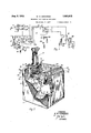
Fig. 2 is a fragmentary perspective view, as seen diagonally from. the side and front,` of the lower housing of a coin collector showing the coin hoppermechanism, a portion of the relay 'operating arm, the toggle linkage mechanism for blocking the relay arm, the connectingmechanism to the'n'iovablel plug in the return chute opening and the construction of the plug and return chute embodied in one form of this invention which is shown in the normal unoperated position;
Fig. 3 is a perspective View in diagrammatic form seen from the same position as Fig. 2 with the plug in the rear-most position showing how a patrons finger is inserted in the return chute to extract the refunded coins. It also shows the manner in which the plug blocks the return chute leading to the coin magnet and how the toggle linkage functions to intercept the coin vane from operation in the refund direction with the plug in this position;
Fig. 4 isa topview of a partial section of the coin return chute mechanism, the section being taken along the lines 4-4 of Fig. 5 with the relay and operating arm omitted. The parts are shown in the normal unoperated position;
Fig. 5 is a sectional side view of the refund mechanism taken along the lines 5 5 of Fig. 4. In this view also, the parts are shown in the normal unoperated position. In this View the coin control magnet With the trigger and ground contact mechanism is shown.
In the drawings, one embodiment of the invention is illustrated in connection with a coin collector of the type disclosed in Patent No. 1,043,219, of November 5, 1912, to O. F. Forsberg. This patent shows the usual coin collector magnet and coin refund chute. This Forsberg magnet and coin hopper are used without change in this invention.
As may be seen by reference to Figs. 2, 4 and 5, the refund chute is provided Within the casing 1 by parallel vertical side walls 68 and 69 'between which an inclined bottom wall 2 is positioned. An opening 3V is formed between these walls through which refunded coins travel `in their passagefrom the coin control apparatus to a vertical opening 4 through which they may be recovered by the patron. A tapered plug 5 is pivoted on a pin 70 so that it normally lls the opening 4 in the return chute closing off the interior of the return chute completely. The pin '70 is provided with av slotted head at one end with a threaded nut on the other end to hold it in place between the side Walls 68 and 69. The plug 5, which may be made of die-cast aluminum, molded bakelite, or fashioned from some other suitable material, has an extension portion 54 with an integral collar 10 which serves as a locating member and a bearing for the plug on the pin 70. A spring l1 made from spring steel Wire or other suitable material is coiled around the collar 10 of the plug 5 and is intendedto keep the plug 5 in its forwardposition or to return it to that position when it is moved to permit the extraction of coins from the return chute. As shown in Fig. 3 when the operator has refunded coins, the patron inserts his finger into the opening 4, pushing plug 5 to the rear so that the coins may be extracted from the depression in the bottom portions 2 of the chute. In this position, plug 5 entirely blocks the opening 3 of the chute so that it protects the coin control magnet from tampering by means of wires or other foreign objects inserted through the return chute. In this position, the opening 12 in the roof 13 of the return chute is also closed by the extension 54 of the plug 5. Referring to Fig. 2 and Fig. 5, the return chute is constructed with the plate 14 at the top of the opening 4. The plug 5 is formed so that in the forward vposition it fits snugly in the opening 4 as it is provided with the magnet 9. Consequently, theV coin 26 will remain on the trap 7. `The armature 66 not having operated, the coin trigger 22 will have prevented the coin trigger 21 from restoring. Consequently, as long as the plug 5 is wedged in the rearmost position, the refunding of coins and the clearing out of the signaling circuit to the central oilice is prevented. This will not, however, prevent the collection 0f coins and the clearing out of the central office ground as heretofore described. However, if at any time the plug is released, the refunding operation can henceforth be accomplished in the normal manner and the signaling circuit to the central office cleared out normally.
Fig. l shows the circuits involved in a manual central oflice A and at the station B for operating the coin collector. When a coin 26 is deposited in the coin chute to obtain a connection, it trips the coin trigger 21, permitting the coin trigger arm 22 to drop and close the ground contact springs 23. A circuit will be established under these conditions over the following path: From grounded contact 23, coils of magnet 9, tip side of line L, closed contact of relay 27, and Winding of relay 23 to battery. The closure of this circuit will energize relay 23 and thereby light lamp 29. .The operator,` noting this light, will insert plug 36 in `jack 31 and cause lamp 29 to be extinguished as follows. The battery 50 is closed through the lamp 47, lighting this lamp, through conductor 43, sleeve contacts of plug 30 and jack 31, energizing relay 27. This opens the contacts of relay 27, deenergizing relay 28 and extinguishing lamp 29. 1n the meantime, it may be assumed that the patron at station B has removed the receiver from the hook and its contacts 33 are closed. This completes a circuit from the battery 39 through the repeating coil winding 46 to the contact 41 of the key 32 through the contact 42 of key 36 to the tip of the plug 3 tip contact of the jack 31 over the tip side of the line L through the talking circuit of the station B, back through the ring side of the line L, jack 31 and plug 30, the contacts 43 of key 36 and contacts 44 of key 32 through the supervisory relay 45, repeating coil winding 46 back to the other side of battery 39. The closure of this circuit causes the energization of relay 45 which closes contacts 49, shunting the lamp 47, but still holding operated the relay 27 from the battery 39. The operator can now communicate with station B and obtain the number desired by the patron calling from station B. ln the event the call is completed, the coin collect key 32 is operated, and the coin 26 deposited in the coin box in the following manner. The operation of key 3,2 closes a circuit from positive battery, lamp 33, winding of relay 34, upper make contact 35 of collect key 32, upper closed contact 53 of key 36, tip contacts of plug 30 and jack 31, tip conductor of line L, windings of magnet 9, closed contact 23 to ground. The closure of the circuit just described will cause lamp 33 to be lighted and relay 34 to be energized. This relay will close a circuit through its make contact from ground and battery through the filament of pilot lamp 37 and cause it to be lighted also. As referred to previously, the energizing of magnet 9 will act on the armature 66 and move the operating arm 8 t0 the left thereby causing the coin 26 to be collected. While the magnet 9 is operated, the
In case the call was not successfully completed to the telephone desired, the above operations would be repeated except that the operator would depress the coin return key 36 instead of the coin collect key 32. The circuit in this event is as follows. The vnegative battery .is connected through lamp 51, relay winding 52, make contact 53 of the key 36 to the station and the. magnet in the manner described for the collect operation. The operation of relay 52 lights thepilot lamp 37. The completion of the circuit to the magnet causes the armature 66 of the magnet 9 to operate inthe refund direction moving the operating arm v8 and the coin vane 6 (Fig. 5) to the right permitting the coin 26 to slide olf the trap 7 into the return chute 3 where it can be recovered by the patron through the opening 4 by the movement of the plug 5. While the armature 66 is held operated in the refund position, the ground contact springs 23 are held closedand the coin trigger arm 22 is raised so that the coin trigger 21 may restore. When the coin return key 36 is released, the magnet 9 is deenergized, the retractile springs restore the armature 66 and the ground contact springs 23 are opened. The operations of disconnecting are the same as were described for the collection of the coin.
However, if the plug 5 is wedged in the rearmost position so that the armature 66 cannot operate to the refund position when the coin return key 36 is operated, the coin trigger arm 22 (Fig. 5) will not be lifted and the coin trigger 21 will remain 'in the tripped position keeping the ground contact springs 23 closed. If the patron realizes before he hangs up that the mechanism is blocked so that the return of the coin cannot proceed in the usual manner, heV
can signal the operator by operating the switchhook to close its contacts 38 so as to deenergize the supervisory relay 45, removing the shunt from the lamp 47 so it will be lighted. The operator will then communicate with the patron and will then be informed by the patron that theV money has not been refunded. The operator can operate the coin return key 36 again and by observation of the lamp 51 and the pilot lamp 37 can determine that 'the coin return current has again been applied to the line and can ascertain in that way that the ground contact springs 23 have not been opened as would be the case with thenormal refunding of the coin. The operator can then operate the coin collect key 32 to collect the coins inasmuch as the magnet 9 is not blocked from operation in the collect direct-ion. The ground .contact springs 23 will then be opened and the operator can determine by subseuuent operation or" the collect key and observation of the lamps 33 and 37 the coins have been collected. The operator can then communicate with the patron and advise him ci the that the refunding mechanism out of order and arrange to reimburse him in the manner provided for such cases.
If the patron has ro the receiver on the hook before noting that the plug is wedged and the refunding mechanism is disabled, the operator will note the religliting of the lamp 47 due to the deenergizing of relay and will disconnect the plug SG from the jack 3l .in the regular Way, no knowing that the c in has not been refunded. Relay 27 will be deenergized by the disconnect operation and as the 'ground contact springs 23 are still closed due to the trigger 21 not having been restored, the relay 28 Will be energized again and the lamp 29 will be relighted. This Will signal the operator again and she Will replace the plug 39 in the jack 31 and communicate with the patron in case he has removed his receiver from the hook and is atthen collect the coin.
The operator ordinarily will then advise the repair forces of the trouble condition existing at the pay station and arrange to have the coin collector restored to normal operation.
It should be noted from the foregoing de scription of this invention that any disabling of the return chute mechanism so that coins will accumulate in the return chute and later be re- Ymoved by the person Who disabled the mechanism is prevented. Furt ermore, the disabling of the return chute mechanism by Wedging the plug in the rearinost position is clearly indicated to the patron by the normal appearance of the v return chute mechanism enabling the patron to A lent collection of money from the return chute 'diierent types of coin return chutes.
by unscrupulous individuals is impossible.
Although the invention has been described in connection with a specific type of coil collector, it may be modied in obvious Ways to meet the requirements of coin collecting apparatus having Likewise, it is applicable to coin collectors connected to dial central oflice lines.
What is claimed is:
1. In a coin collecting device including a rcturn chute adapted to receive and retain refunded coins temporarily, a magnet for controlling the movement of the coins to said chute and means normally disconnected irpm said magnet for mechanically causing its imbalance to prevent the movement of coins to the return chute When said chute is rendered inoperative.
2. In a coin collecting device, a coin control magnet for collecting or refunding coins in ac- ;cordance with the character of the current applied thereto, a return chute adapted to reth o, a return chute with an accessible p0rtion to receive refunded coins, and means norinallyconnected from` said coin control magnet for mechanically obstructing said coin control from operating in the refund upon the rendering of said rcturn chute inoativc for the return of said coins by fraudul nt anip-ulation, said means being disconnected from the coin control magnet and clearing said coin control magnet for operation in the refund direction upon the return chute being made operative for the return of said coins.
fl. In a coin collecting device, a magnet for controlling the collecting and refunding of coins, a return chute associated with `said magnet and adapted to receive 'refunded coins, and toggle means for obstructing said magnet from operating to refund coins upon the disabling of the return chute by fraudulent manipulation.
5. ln a coin collecting device, a magnet Ifor controlling the collecting and refunding of coins, a ret "rn chute associated with said magnet and adapted to receive refunded coins, and toggle means for obstructing said magnet from refunding coins upon the disabling of the return chute by fraude-.lent operation, and for clearing said magnet for refunding vcoins upon the restoration of the return chute to operative condition.
Sfln a coin collecting device, a magnet for controlling the c llecting and refunding ofcoins, a return chute associated with said magnet and adapted to receive refunded coins, toggle means normally disconnected from saidl coin control magnet for obstructing said coin control magnet from refunong coins upon the disabling of the return chute by fraudulent operation, said toggle means being arranged for clearing said coin control magnet for refunding coins upon the restoration of the return chute to operative condition, said toggle means being also arranged for permittingthe collecting of coins With the return chute inoperative and operative.
7. In a coin collecting device, a coin control magnet for collecting or refunding coins in accordance with the polarity of the current applied thereto, a return chute adapted to retain refunded coins temporarily, and 'toggle means normally disconnected from said coin control magnet for obstructing said coin control magnet from refunding coins during the application of refund current upon the disabling of the return chute by fraudulent operation, the collecting of coins by the coin control magnet during the application of collect current being unalfected, said toggle means being adapted to clear coin control magnet for refunding coins during tl e application of refund current upon restoration of the return chute to operative condition.
8. In a coin collecting device including a coin control magnet, a return chute for said device having an exit opening normally closed, and means to imbalance the coin control magnet upon the rendering of said return chute ineffective by fraudulent manipulation for the refunding of coins.
9. In a coin collecting device including a coin control magnet and a return chute, a plug normally closing the exit opening from said return chute, said plug being movable to clear said exit opening for extracting refunded coins, and means associated With said plug for disabling said coin control magnet from refunding coins when said plug is moved to clear the exit opening.
1G. In a coin collecting device, a coin control magnet for collecting or refunding coins in accordance With the polarity of the current applied thereto, a return coin chute having an exit opening, a movable plug normally closing said exit opening, said plug preventing access to the coin control magnet by the insertion of foreign material through said return chute, said plug also being adapted to prevent the stufling of foreign material into the return chute past said plug, and means responsive to the fraudulent manipulation of said plug to prevent the removal of refunded coins by obstructing the coin control magnet from operating in the refund direction upon the applicationA of refund current.
11. In a telephone system including a central station and a substation connected thereto, coin collect and coin return keys at the central station, a coin collecting device including a coin control magnet at the substation, a return coin chute for the collecting device, and mechanical means normally disconnected from said coin control magnet, said means being actuated in response to fraudulent manipulation to disable said return chute by obstructing said coin con trol magnet from discharging coins into the return coin chute upon the operation of the coin collect or coin return keys.
12. In a telephone system including a central station and a substation connected thereto, coin collect and coin return keys at the central station, a coin collecting device at the substation, a coin control magnet therefor, a return coin chute and a collect coin chute associated With said magnet, and toggle linkage means actuated by the disabling of said return coin chute for obstructing said coin control magnet to prevent the discharge of coins to the return coin chute upon the operation of the coin return key and to permit the passage of coins to said collect chute upon the operation of said coin collect key.
13. In a telephone system including a central station and a substation connected thereto, coin collect and coin return keys at the central station, a coin collecting device at the substation, a coin control magnet therefor, a return chute associated with said magnet having an exit opening, a plug for normally closing said opening and means to unbalance the coin control magnet upon the rendering of said return chute ineffective when said plug is tampered with to prevent the refunding of coins by the operation of the coin collect key.
14. In a telephone system including a central station and a substation connected thereto, coin collect and coin return keys at a central station, a coin collecting device at the substation, a coin control magnet therefor, a return chute having an exit opening, a plug normally closing said opening, said plug being movable to extract refunded coins from said return chute, and toggle means associated with said plug for preventing sai-:l coin control magnet from refunding coins upon the operation of the coin return key when said plug is clear of said exit opening and to permit the passage of coins to said collect chute upon the operation of said coin collect key.
15. In a coin collecting device, a coin control magnet therefor, a return chute leading from said coin control magnet having a depression adapted to receive and retain refunded coins temporarily and an exit opening through which the coins may be recovered, and means for closing said exit opening while said return chute is receptive to the discharge of coins from said coin control magnet into said depression, said means being movable upon the extraction of coins from `said return chute depression to close said return chute against the discharge of coins and against attempts at fraudulent manipulation of the coin collecting device.
WILLIAM H. EDWARDS.
Priority Applications (1)
| Application Number | Priority Date | Filing Date | Title |
|---|---|---|---|
| US640895A US1921072A (en) | 1932-11-02 | 1932-11-02 | Telephone pay station apparatus |
Applications Claiming Priority (1)
| Application Number | Priority Date | Filing Date | Title |
|---|---|---|---|
| US640895A US1921072A (en) | 1932-11-02 | 1932-11-02 | Telephone pay station apparatus |
Publications (1)
| Publication Number | Publication Date |
|---|---|
| US1921072A true US1921072A (en) | 1933-08-08 |
Family
ID=24570112
Family Applications (1)
| Application Number | Title | Priority Date | Filing Date |
|---|---|---|---|
| US640895A Expired - Lifetime US1921072A (en) | 1932-11-02 | 1932-11-02 | Telephone pay station apparatus |
Country Status (1)
| Country | Link |
|---|---|
| US (1) | US1921072A (en) |
Cited By (7)
| Publication number | Priority date | Publication date | Assignee | Title |
|---|---|---|---|---|
| US4761809A (en) * | 1987-07-27 | 1988-08-02 | Nynex Corporation | Coin return chute for telephone pay station |
| US4946095A (en) * | 1988-11-22 | 1990-08-07 | Salvatore Anello | Change return protection device |
| US5102038A (en) * | 1988-11-22 | 1992-04-07 | Salvatore Anello | Change return protection device |
| US5361979A (en) * | 1992-11-25 | 1994-11-08 | Sandt Technology, Ltd. | Change return protection device |
| US5411207A (en) * | 1993-07-21 | 1995-05-02 | Calstar Technologies, Inc. | Protective coin return for telephone paystation |
| US5431338A (en) * | 1993-07-21 | 1995-07-11 | Calstar Technologies, Inc. | Protective coin return for telephone paystation |
| US6378685B1 (en) * | 1999-03-29 | 2002-04-30 | Aruze Co., Ltd. | Coin-receiving device |
-
1932
- 1932-11-02 US US640895A patent/US1921072A/en not_active Expired - Lifetime
Cited By (7)
| Publication number | Priority date | Publication date | Assignee | Title |
|---|---|---|---|---|
| US4761809A (en) * | 1987-07-27 | 1988-08-02 | Nynex Corporation | Coin return chute for telephone pay station |
| US4946095A (en) * | 1988-11-22 | 1990-08-07 | Salvatore Anello | Change return protection device |
| US5102038A (en) * | 1988-11-22 | 1992-04-07 | Salvatore Anello | Change return protection device |
| US5361979A (en) * | 1992-11-25 | 1994-11-08 | Sandt Technology, Ltd. | Change return protection device |
| US5411207A (en) * | 1993-07-21 | 1995-05-02 | Calstar Technologies, Inc. | Protective coin return for telephone paystation |
| US5431338A (en) * | 1993-07-21 | 1995-07-11 | Calstar Technologies, Inc. | Protective coin return for telephone paystation |
| US6378685B1 (en) * | 1999-03-29 | 2002-04-30 | Aruze Co., Ltd. | Coin-receiving device |
Similar Documents
| Publication | Publication Date | Title |
|---|---|---|
| US1921072A (en) | Telephone pay station apparatus | |
| US2251073A (en) | Coin collector | |
| US4136262A (en) | Telephone paystation | |
| US3087018A (en) | Ticket operated telephone set | |
| US4123623A (en) | Pay telephone alarm and audit system | |
| US2179091A (en) | Coin collector | |
| US4206321A (en) | Pay telephone alarm system with audit means | |
| US2278436A (en) | Telephone coin collector | |
| US2072462A (en) | Coin collector | |
| US1921071A (en) | Telephone pay station apparatus | |
| US2204083A (en) | Coin collector | |
| US5787158A (en) | Smart bucket | |
| US2283396A (en) | Telephone coin collector | |
| US1901944A (en) | Telephone system | |
| US1887576A (en) | Telephone pay station apparatus | |
| US2004615A (en) | Coin collecting apparatus | |
| US2029113A (en) | Telephone coin collector | |
| US2236571A (en) | Coin collector | |
| US2642496A (en) | Telephone pay station coin box system | |
| US2881254A (en) | Postpay paystation with coin control circuit | |
| US2035280A (en) | Coin collector | |
| US751081A (en) | Coin-controlled telephone apparatus | |
| US2066391A (en) | Pay telephone station | |
| US2974199A (en) | Telephone paystation circuit with coin-accept control | |
| US2332018A (en) | Coin collector |