US1908505A - Fluid pressure braking system - Google Patents
Fluid pressure braking system Download PDFInfo
- Publication number
- US1908505A US1908505A US421491A US42149130A US1908505A US 1908505 A US1908505 A US 1908505A US 421491 A US421491 A US 421491A US 42149130 A US42149130 A US 42149130A US 1908505 A US1908505 A US 1908505A
- Authority
- US
- United States
- Prior art keywords
- pressure
- systems
- piston
- fluid pressure
- cylinder
- Prior art date
- Legal status (The legal status is an assumption and is not a legal conclusion. Google has not performed a legal analysis and makes no representation as to the accuracy of the status listed.)
- Expired - Lifetime
Links
Images
Classifications
-
- B—PERFORMING OPERATIONS; TRANSPORTING
- B60—VEHICLES IN GENERAL
- B60T—VEHICLE BRAKE CONTROL SYSTEMS OR PARTS THEREOF; BRAKE CONTROL SYSTEMS OR PARTS THEREOF, IN GENERAL; ARRANGEMENT OF BRAKING ELEMENTS ON VEHICLES IN GENERAL; PORTABLE DEVICES FOR PREVENTING UNWANTED MOVEMENT OF VEHICLES; VEHICLE MODIFICATIONS TO FACILITATE COOLING OF BRAKES
- B60T11/00—Transmitting braking action from initiating means to ultimate brake actuator without power assistance or drive or where such assistance or drive is irrelevant
- B60T11/10—Transmitting braking action from initiating means to ultimate brake actuator without power assistance or drive or where such assistance or drive is irrelevant transmitting by fluid means, e.g. hydraulic
- B60T11/24—Single initiating means operating on more than one circuit, e.g. dual circuits
-
- Y—GENERAL TAGGING OF NEW TECHNOLOGICAL DEVELOPMENTS; GENERAL TAGGING OF CROSS-SECTIONAL TECHNOLOGIES SPANNING OVER SEVERAL SECTIONS OF THE IPC; TECHNICAL SUBJECTS COVERED BY FORMER USPC CROSS-REFERENCE ART COLLECTIONS [XRACs] AND DIGESTS
- Y10—TECHNICAL SUBJECTS COVERED BY FORMER USPC
- Y10T—TECHNICAL SUBJECTS COVERED BY FORMER US CLASSIFICATION
- Y10T137/00—Fluid handling
- Y10T137/2496—Self-proportioning or correlating systems
- Y10T137/2514—Self-proportioning flow systems
- Y10T137/2521—Flow comparison or differential response
Definitions
- This invention relates to fluid pressure braking systems, more particularly for motor vehicles, of the kind comprising two separate systems each complete in itself and consisting of a pressure-producing unit or device adapted automatically to make up any loss of fluid in the system and communicating through a suitable fluid pressure pipe or system of pipes with pressure-operated means associated with the respective brakes to be applied, the two separate pressure-producing units or devices being actuated by a common lever or other operating member and the separate systems being rendered normally interdependent as regards the fluid pressure therein by means of a balancing device adapted to ensure equal pressures in the systems and that, further, should a defect occur in one 01 the systems to render the pressure fluid incfiective for applying the brakes, the other system will remain operative.
- the pressure-producing pistons of the respcctive systems are connected to a doublearmed lever pivoted centrally to the brakeoperating member to ensure equalizing of the pressures in the two systems, and the angular movement of the lever about its pivotal axis is limited so that should one system fail the full pressure of the brake-operating member will remain effective on the other system.
- the invention has for its object to provide an improved, simple and efiective construction of balancing device. 7
- the balancing device comprises a cylinder fitted with a single centrally arranged piston having an outwardly directed cup washer or other suitable packing at each end, the cylinder communicating at opposite ends with the separate systems and stops being provided for the purpose of limiting the axial movement of the piston in one direction or the other.
- the piston would move into engagement with the respective stop and thereafter the pressure onthe brake-operating member would be exerted solely upon the remaining system.
- the stops consist of integral inwardly extending projections upon screwed plugs or equivalent members closing the end of the cylinder.
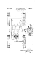
- 2-- Figure 1 is a diagrammatic plan view partly in section illustrating a fluid pressure brtking system according to the invention
- Figure 2 is a detail cross-sectional View of the balancing device.
- each of the front brake drums 1 and of the rear brake drums 2 may be provided with a single pair of braking shoes 3, l respectively, orthe equivalent adapted to be actuated respectively by a suitable pressure-operated device 5, 6 conveniently comprising an open-ended cylinder fitted with a pair of opposed pistons, as described in theprior specification No. 1,721,370.
- the pressure-operated devices of the brakes of one pair of wheels, for example the front pair 1 are connected to a fluid pressure pipe 7 or pipe system communicating with a suitable pressure-producing unit 8 or device advantageously of the kind described and claimed in the prior British specification No. 280,502.
- the pressure-operated devices 6 of the other or rear pair of brakes 2 are connected to a separate fluid pressure pipe 9 or pipe system communicating with a separate pressure-producing unit 10 or device, the two pressure-producing units 8 and'10 or devices being arranged or adapted to be operated by a common brake lever 11 or equivalent member.
- a balancing or pressure-compensating device 12 is inserted at a suitable intermediate position in the fluid pressure pipes 7 and 9, a balancing or pressure-compensating device 12 is inserted.
- llhis device 12 consists of a hollow cylinder 13 closed at the ends by means of screwed plugs 14 or the like and provided adjacent each end with a pair of laterally extending bosses 15, 16 having screwthrcaded holes communicating at their inner ends with the respective end of the cylinder 13 and adapted for connection with the respective pipe lines 7 and 8.
- the piston 17 in the balancing or pressure-compensating device will be forced over by the difference in pressure between the defective system and the system which is still operative until it engages with the respective fixed stop 19 or 20, whereupon the unaflfected system will continue to function in the normal manner.
- the pressure applied to the brake lever 11 or the equivalent is divided substantially equally between the two systems 7, 9.
- the whole of the pressure applied to the brake lever 11 or the like is communicated to the unaffected system with corresponding increase in the pressure with which the respective brakes are applied. For this reason it will be understood that the braking effect, neglecting the wheel slip will. be substantially the same when onesystem only is operative as when both systems are operating correctly.
- a fluid pressure braking means involving independent hydraulic systems, manual means for creating braking pressure in said systems, and a balancing device intermediate the systems and including a floating piston responsive only to the pressure of each system an serving to prevent fluid interchange between the systems, the movement of the piston in one direction under a limited excess pressure in one system serving in such movement to balance the pressures in the respective systems,
- a fluid pressure braking means including independent hydraulic brake controlling systems, a balancing device for equalizing pressure between the systems including a floating piston responsive solely to an excess pressure in one of the systems and moving under such excess pressure to increase the pressure in the other system and reduce the pressure in the first mentioned system to a pressure balancing point, and means for limiting pressure responsive movement of the piston in either direction toprevent pressure exchange between the systems beyond a predetermined limit of pressure variation in the respective systems.
- a fluid pressure braking means including independent brake controlling hydraulic s stems, a pressure balancing means between the systems including a cylinder closed at the respective ends, a piston operative within the cylinder and normally defining chambers beyond each end of the piston, each pressure system including one of said chambers, the piston floating with respect to the chambers and solely responsive to variation in pressure in the chambers, said piston further preventing fluid exchange between the chambers, said piston under variation in pressure in one of the chambers andthereby in the system of which said chamber forms a part moving to reduce the normal volume of the other chamber to thereby increase the pressure in such other chamber and in the system in which said other chamber forms a part.
- a fluid pressure braking means including independent brake controlling hydraulic systems, a pressure balancing means between the systems including a cylinder closed at the respective ends, a piston operative Within the cylinder and normally defining chambers beyond each end of the piston, each ressure system including one of said cham ers, the piston floating with respect to the chambers and solely responsive to variation in pressure in the chambers, said piston further preventing fluid exchange between the chambers, said piston under variation in pressure in one of the chambers and thereby in the system of which said chamber forms a part moving to reduce the normal volume of the other chamber to thereby increase the .pressure in such other chamber and in the system in which said other chamber forms a part, and means for limiting pressure responsive movement of the piston in either direction.
- a fluid pressure braking means including independent braking systems, an equalizing device arranged between the systems including a cylinder, plugs closing the respective ends of the cylinder, a piston floating in the cylinder and defining between each end thereof and the adjacent plug a chamber, each fiuid pressure system including one of said chambers, the piston being normally balanced by the rexure of the fluid in the respective cham rs and being influenced solely by an excess pressure in one of said chambers,
Landscapes
- Engineering & Computer Science (AREA)
- Transportation (AREA)
- Mechanical Engineering (AREA)
- Braking Arrangements (AREA)
- Hydraulic Control Valves For Brake Systems (AREA)
- Braking Systems And Boosters (AREA)
- Valves And Accessory Devices For Braking Systems (AREA)
Description
May 9, 1933. E, BQUGHTON ET AL 1,998,505
FLUID PRESSURE BRAKING SYSTEM Filed Jan. 17, 1930 Patented ay 9, 1933 EDWARD BISHOP BOUGHTON, WILLIE EMMOTT, AND DENIS TABUR BEUGIK, 0E LQNDQN,
ENGLAND FLUID PRESSURE BRAKING- SYSTEM Application filed January 17, 1930, Serial No. 421,491, and in Great Britain January 2'35, 11929.
This invention relates to fluid pressure braking systems, more particularly for motor vehicles, of the kind comprising two separate systems each complete in itself and consisting of a pressure-producing unit or device adapted automatically to make up any loss of fluid in the system and communicating through a suitable fluid pressure pipe or system of pipes with pressure-operated means associated with the respective brakes to be applied, the two separate pressure-producing units or devices being actuated by a common lever or other operating member and the separate systems being rendered normally interdependent as regards the fluid pressure therein by means of a balancing device adapted to ensure equal pressures in the systems and that, further, should a defect occur in one 01 the systems to render the pressure fluid incfiective for applying the brakes, the other system will remain operative.
In the known system of the kind referred to, the pressure-producing pistons of the respcctive systems are connected to a doublearmed lever pivoted centrally to the brakeoperating member to ensure equalizing of the pressures in the two systems, and the angular movement of the lever about its pivotal axis is limited so that should one system fail the full pressure of the brake-operating member will remain effective on the other system.
The invention has for its object to provide an improved, simple and efiective construction of balancing device. 7
According to the invention, the balancing device comprises a cylinder fitted with a single centrally arranged piston having an outwardly directed cup washer or other suitable packing at each end, the cylinder communicating at opposite ends with the separate systems and stops being provided for the purpose of limiting the axial movement of the piston in one direction or the other. It will be understood that in such a construction, on failure or breakage of one system, the piston would move into engagement with the respective stop and thereafter the pressure onthe brake-operating member would be exerted solely upon the remaining system. Conveniently, the stops consist of integral inwardly extending projections upon screwed plugs or equivalent members closing the end of the cylinder.
The invention is hereinafter described by way of example with reference to the accoinpanying diagrammatic drawing, in which 2-- Figure 1 is a diagrammatic plan view partly in section illustrating a fluid pressure brtking system according to the invention; an
Figure 2 is a detail cross-sectional View of the balancing device.
lln carrying the invention into efiect and in the application of the invention to a fourwheeled motor vehicle, each of the front brake drums 1 and of the rear brake drums 2 may be provided with a single pair of braking shoes 3, l respectively, orthe equivalent adapted to be actuated respectively by a suitable pressure-operated device 5, 6 conveniently comprising an open-ended cylinder fitted with a pair of opposed pistons, as described in theprior specification No. 1,721,370. The pressure-operated devices of the brakes of one pair of wheels, for example the front pair 1, are connected to a fluid pressure pipe 7 or pipe system communicating with a suitable pressure-producing unit 8 or device advantageously of the kind described and claimed in the prior British specification No. 280,502. Similarly, the pressure-operated devices 6 of the other or rear pair of brakes 2 are connected to a separate fluid pressure pipe 9 or pipe system communicating with a separate pressure-producing unit 10 or device, the two pressure-producing units 8 and'10 or devices being arranged or adapted to be operated by a common brake lever 11 or equivalent member. At a suitable intermediate position in the fluid pressure pipes 7 and 9, a balancing or pressure-compensating device 12 is inserted. llhis device 12 consists of a hollow cylinder 13 closed at the ends by means of screwed plugs 14 or the like and provided adjacent each end with a pair of laterally extending bosses 15, 16 having screwthrcaded holes communicating at their inner ends with the respective end of the cylinder 13 and adapted for connection with the respective pipe lines 7 and 8. A single piston 17, having at each end an outwardly directed cup washer 18 or other suitable packing, is provided in the cylinder 13 in an intermediate position and is capable of free movement therein within limits determined by fixed stops 19, 20 conveniently consisting of integral inwardly extending projections upon the screwed plugs 14 or closure members at the ends of the cylinder 13.
In the normal operation of the combined systems, movement of the brake lever 11 or equivalent member to apply the brakes will exert substantially the same pressure in each of the systems 7 and 9, any difference in pressure between the systems being equalized, and any variation of the displacement required in the pressure-producing devices 8, 10 to compensate for varying backlash or clearance between the shoes and the brake drums in the off position being taken up, by movement of the piston 17 of the balancing or pressurecompensating device 12 towards one end or the other of the cylinder 13. In the event of failure of one of the systems, the piston 17 in the balancing or pressure-compensating device will be forced over by the difference in pressure between the defective system and the system which is still operative until it engages with the respective fixed stop 19 or 20, whereupon the unaflfected system will continue to function in the normal manner. It will be understood that when both systems are operating, the pressure applied to the brake lever 11 or the equivalent is divided substantially equally between the two systems 7, 9. When, however, one system fails, the whole of the pressure applied to the brake lever 11 or the like is communicated to the unaffected system with corresponding increase in the pressure with which the respective brakes are applied. For this reason it will be understood that the braking effect, neglecting the wheel slip will. be substantially the same when onesystem only is operative as when both systems are operating correctly.
It will be understood that the invention is applicable to fluid pressure braking systems of the kind referred to wherein more than two separate systems are employed and wherein the systems are arranged otherwise than as hereinbefore described with reference to the drawing.
What we claim is 1. A fluid pressure braking means involving independent hydraulic systems, manual means for creating braking pressure in said systems, and a balancing device intermediate the systems and including a floating piston responsive only to the pressure of each system an serving to prevent fluid interchange between the systems, the movement of the piston in one direction under a limited excess pressure in one system serving in such movement to balance the pressures in the respective systems,
2. A fluid pressure braking means including independent hydraulic brake controlling systems, a balancing device for equalizing pressure between the systems including a floating piston responsive solely to an excess pressure in one of the systems and moving under such excess pressure to increase the pressure in the other system and reduce the pressure in the first mentioned system to a pressure balancing point, and means for limiting pressure responsive movement of the piston in either direction toprevent pressure exchange between the systems beyond a predetermined limit of pressure variation in the respective systems.
3. A fluid pressure braking means including independent brake controlling hydraulic s stems, a pressure balancing means between the systems including a cylinder closed at the respective ends, a piston operative within the cylinder and normally defining chambers beyond each end of the piston, each pressure system including one of said chambers, the piston floating with respect to the chambers and solely responsive to variation in pressure in the chambers, said piston further preventing fluid exchange between the chambers, said piston under variation in pressure in one of the chambers andthereby in the system of which said chamber forms a part moving to reduce the normal volume of the other chamber to thereby increase the pressure in such other chamber and in the system in which said other chamber forms a part.
4. A fluid pressure braking means including independent brake controlling hydraulic systems, a pressure balancing means between the systems including a cylinder closed at the respective ends, a piston operative Within the cylinder and normally defining chambers beyond each end of the piston, each ressure system including one of said cham ers, the piston floating with respect to the chambers and solely responsive to variation in pressure in the chambers, said piston further preventing fluid exchange between the chambers, said piston under variation in pressure in one of the chambers and thereby in the system of which said chamber forms a part moving to reduce the normal volume of the other chamber to thereby increase the .pressure in such other chamber and in the system in which said other chamber forms a part, and means for limiting pressure responsive movement of the piston in either direction.
5. A fluid pressure braking means including independent braking systems, an equalizing device arranged between the systems including a cylinder, plugs closing the respective ends of the cylinder, a piston floating in the cylinder and defining between each end thereof and the adjacent plug a chamber, each fiuid pressure system including one of said chambers, the piston being normally balanced by the rexure of the fluid in the respective cham rs and being influenced solely by an excess pressure in one of said chambers,
to thereby increase the pressure in the other of such chambers and correspondin 1y re *duce pressure in the first mentioned c amber to a balance, and projections from each of the cylinder closing plugs to limit movement of the piston in each direction, whereby a predommating pressure in one system in excess of a predetermined limit W111 operate the iston to its stop position to maintain the lntegrity of the excess pressure system without regard to pressure losses in the other system in excess of the limit for which the balancing device is set.
EDWARD BISHOP BOUGHTON.
WILLIE EMIMOTT.
DENIS TABOR BROCK.
Applications Claiming Priority (1)
| Application Number | Priority Date | Filing Date | Title |
|---|---|---|---|
| GB2683/29A GB328305A (en) | 1929-01-25 | 1929-01-25 | Improvements in or relating to fluid pressure braking systems |
Publications (1)
| Publication Number | Publication Date |
|---|---|
| US1908505A true US1908505A (en) | 1933-05-09 |
Family
ID=9743930
Family Applications (2)
| Application Number | Title | Priority Date | Filing Date |
|---|---|---|---|
| US421492A Expired - Lifetime US2008975A (en) | 1929-01-25 | 1930-01-17 | Fluid pressure braking system |
| US421491A Expired - Lifetime US1908505A (en) | 1929-01-25 | 1930-01-17 | Fluid pressure braking system |
Family Applications Before (1)
| Application Number | Title | Priority Date | Filing Date |
|---|---|---|---|
| US421492A Expired - Lifetime US2008975A (en) | 1929-01-25 | 1930-01-17 | Fluid pressure braking system |
Country Status (4)
| Country | Link |
|---|---|
| US (2) | US2008975A (en) |
| DE (2) | DE526588C (en) |
| FR (2) | FR688918A (en) |
| GB (2) | GB328307A (en) |
Cited By (1)
| Publication number | Priority date | Publication date | Assignee | Title |
|---|---|---|---|---|
| US3447835A (en) * | 1967-07-06 | 1969-06-03 | Edwin H Parkhurst Jr | Vehicle brake system and valve |
Families Citing this family (10)
| Publication number | Priority date | Publication date | Assignee | Title |
|---|---|---|---|---|
| US2563168A (en) * | 1948-09-10 | 1951-08-07 | David R Herriott | Safety device for fluid brakes |
| DE968745C (en) * | 1952-12-31 | 1958-03-27 | Bergische Achsen Kotz Soehne | Brake system for motor vehicles, in particular truck trailers |
| DE1093228B (en) * | 1955-11-30 | 1960-11-17 | Daimler Benz Ag | Arrangement of the wheel brake cylinder in hydraulic brake actuation systems for vehicles, especially motor vehicles |
| US3033324A (en) * | 1956-03-08 | 1962-05-08 | Ferodo Sa | Vehicle brake control and balancing system |
| US2947145A (en) * | 1958-06-06 | 1960-08-02 | William E Choate | Multiple master cylinder |
| DE1243540B (en) * | 1963-05-30 | 1967-06-29 | Teves Kg Alfred | Dual circuit main cylinder, especially for motor vehicles |
| US3517782A (en) * | 1968-08-26 | 1970-06-30 | Kelsey Hayes Co | Dual braking system including a disc brake piston and cylinder construction |
| US3680314A (en) * | 1969-11-19 | 1972-08-01 | Francis J Toomey | Hydraulic emergency brake system |
| US3888551A (en) * | 1970-04-30 | 1975-06-10 | Antonio Maria Castello B Neves | Apparatus for controlling the actuation of the brakes of a motor vehicle |
| US4249643A (en) * | 1976-11-04 | 1981-02-10 | Yoder Brake & Manufacturing Co., Inc. | Method and apparatus for actuating trailer brakes |
-
1929
- 1929-01-25 GB GB38798/29A patent/GB328307A/en not_active Expired
- 1929-01-25 GB GB2683/29A patent/GB328305A/en not_active Expired
-
1930
- 1930-01-17 US US421492A patent/US2008975A/en not_active Expired - Lifetime
- 1930-01-17 US US421491A patent/US1908505A/en not_active Expired - Lifetime
- 1930-01-24 DE DE1930526588D patent/DE526588C/en not_active Expired
- 1930-01-25 FR FR688918D patent/FR688918A/en not_active Expired
- 1930-01-25 FR FR688919D patent/FR688919A/en not_active Expired
- 1930-01-25 DE DE1930558036D patent/DE558036C/en not_active Expired
Cited By (1)
| Publication number | Priority date | Publication date | Assignee | Title |
|---|---|---|---|---|
| US3447835A (en) * | 1967-07-06 | 1969-06-03 | Edwin H Parkhurst Jr | Vehicle brake system and valve |
Also Published As
| Publication number | Publication date |
|---|---|
| GB328305A (en) | 1930-04-25 |
| FR688919A (en) | 1930-08-30 |
| GB328307A (en) | 1930-04-25 |
| DE558036C (en) | 1932-08-31 |
| FR688918A (en) | 1930-08-30 |
| DE526588C (en) | 1931-06-08 |
| US2008975A (en) | 1935-07-23 |
Similar Documents
| Publication | Publication Date | Title |
|---|---|---|
| US1908505A (en) | Fluid pressure braking system | |
| US3169800A (en) | Brake regulator | |
| US3477549A (en) | Dual automotive brake system | |
| US2918148A (en) | Hydraulic brake system for motor vehicles | |
| US1905077A (en) | Safety means for hydraulic brakes | |
| US2227245A (en) | Brake | |
| US2095560A (en) | Safety mechanism for hydraulically operated braking systems | |
| US2173928A (en) | Fluid pressure brake | |
| US3120244A (en) | Control valve unit | |
| US2167721A (en) | Brake | |
| US2128853A (en) | Safety device for hydraulic brakes | |
| US3650569A (en) | Brake regulator for automotive vehicle | |
| US2238124A (en) | Brake | |
| US3304130A (en) | Hydraulic valves | |
| US2111930A (en) | Hydraulic brake connection | |
| US3414334A (en) | Delaying action equalizer valve | |
| US3035870A (en) | Ratio changing means for fluid actuated brakes | |
| GB1222818A (en) | Improvements in or relating to brake pressure control valves | |
| US2219041A (en) | Brake equalizer | |
| US2189224A (en) | Brake | |
| US3701567A (en) | Combination proportioning and bypass valve | |
| US3520577A (en) | Hydraulic braking systems | |
| US2141688A (en) | Brake mechanism | |
| US2920451A (en) | Ratio changer | |
| US2001971A (en) | Brake |