US1868149A - Automatic door opener and closer - Google Patents
Automatic door opener and closer Download PDFInfo
- Publication number
- US1868149A US1868149A US396221A US39622129A US1868149A US 1868149 A US1868149 A US 1868149A US 396221 A US396221 A US 396221A US 39622129 A US39622129 A US 39622129A US 1868149 A US1868149 A US 1868149A
- Authority
- US
- United States
- Prior art keywords
- doors
- door
- circuit
- switch
- motors
- Prior art date
- Legal status (The legal status is an assumption and is not a legal conclusion. Google has not performed a legal analysis and makes no representation as to the accuracy of the status listed.)
- Expired - Lifetime
Links
Images


Classifications
-
- E—FIXED CONSTRUCTIONS
- E05—LOCKS; KEYS; WINDOW OR DOOR FITTINGS; SAFES
- E05F—DEVICES FOR MOVING WINGS INTO OPEN OR CLOSED POSITION; CHECKS FOR WINGS; WING FITTINGS NOT OTHERWISE PROVIDED FOR, CONCERNED WITH THE FUNCTIONING OF THE WING
- E05F15/00—Power-operated mechanisms for wings
- E05F15/60—Power-operated mechanisms for wings using electrical actuators
- E05F15/603—Power-operated mechanisms for wings using electrical actuators using rotary electromotors
- E05F15/611—Power-operated mechanisms for wings using electrical actuators using rotary electromotors for swinging wings
- E05F15/616—Power-operated mechanisms for wings using electrical actuators using rotary electromotors for swinging wings operated by push-pull mechanisms
- E05F15/619—Power-operated mechanisms for wings using electrical actuators using rotary electromotors for swinging wings operated by push-pull mechanisms using flexible or rigid rack-and-pinion arrangements
-
- E—FIXED CONSTRUCTIONS
- E05—LOCKS; KEYS; WINDOW OR DOOR FITTINGS; SAFES
- E05Y—INDEXING SCHEME RELATING TO HINGES OR OTHER SUSPENSION DEVICES FOR DOORS, WINDOWS OR WINGS AND DEVICES FOR MOVING WINGS INTO OPEN OR CLOSED POSITION, CHECKS FOR WINGS AND WING FITTINGS NOT OTHERWISE PROVIDED FOR, CONCERNED WITH THE FUNCTIONING OF THE WING
- E05Y2201/00—Constructional elements; Accessories therefore
- E05Y2201/40—Motors; Magnets; Springs; Weights; Accessories therefore
- E05Y2201/43—Motors
- E05Y2201/434—Electromotors; Details thereof
-
- E—FIXED CONSTRUCTIONS
- E05—LOCKS; KEYS; WINDOW OR DOOR FITTINGS; SAFES
- E05Y—INDEXING SCHEME RELATING TO HINGES OR OTHER SUSPENSION DEVICES FOR DOORS, WINDOWS OR WINGS AND DEVICES FOR MOVING WINGS INTO OPEN OR CLOSED POSITION, CHECKS FOR WINGS AND WING FITTINGS NOT OTHERWISE PROVIDED FOR, CONCERNED WITH THE FUNCTIONING OF THE WING
- E05Y2201/00—Constructional elements; Accessories therefore
- E05Y2201/60—Suspension or transmission members; Accessories therefore
- E05Y2201/622—Suspension or transmission members elements
- E05Y2201/71—Toothed gearing
- E05Y2201/722—Racks
-
- E—FIXED CONSTRUCTIONS
- E05—LOCKS; KEYS; WINDOW OR DOOR FITTINGS; SAFES
- E05Y—INDEXING SCHEME RELATING TO HINGES OR OTHER SUSPENSION DEVICES FOR DOORS, WINDOWS OR WINGS AND DEVICES FOR MOVING WINGS INTO OPEN OR CLOSED POSITION, CHECKS FOR WINGS AND WING FITTINGS NOT OTHERWISE PROVIDED FOR, CONCERNED WITH THE FUNCTIONING OF THE WING
- E05Y2400/00—Electronic control; Power supply; Power or signal transmission; User interfaces
- E05Y2400/10—Electronic control
- E05Y2400/50—Fault detection
- E05Y2400/502—Fault detection of components
-
- E—FIXED CONSTRUCTIONS
- E05—LOCKS; KEYS; WINDOW OR DOOR FITTINGS; SAFES
- E05Y—INDEXING SCHEME RELATING TO HINGES OR OTHER SUSPENSION DEVICES FOR DOORS, WINDOWS OR WINGS AND DEVICES FOR MOVING WINGS INTO OPEN OR CLOSED POSITION, CHECKS FOR WINGS AND WING FITTINGS NOT OTHERWISE PROVIDED FOR, CONCERNED WITH THE FUNCTIONING OF THE WING
- E05Y2600/00—Mounting or coupling arrangements for elements provided for in this subclass
- E05Y2600/40—Mounting location; Visibility of the elements
- E05Y2600/46—Mounting location; Visibility of the elements in or on the wing
-
- E—FIXED CONSTRUCTIONS
- E05—LOCKS; KEYS; WINDOW OR DOOR FITTINGS; SAFES
- E05Y—INDEXING SCHEME RELATING TO HINGES OR OTHER SUSPENSION DEVICES FOR DOORS, WINDOWS OR WINGS AND DEVICES FOR MOVING WINGS INTO OPEN OR CLOSED POSITION, CHECKS FOR WINGS AND WING FITTINGS NOT OTHERWISE PROVIDED FOR, CONCERNED WITH THE FUNCTIONING OF THE WING
- E05Y2800/00—Details, accessories and auxiliary operations not otherwise provided for
- E05Y2800/40—Protection
- E05Y2800/404—Protection against component faults or failure
-
- E—FIXED CONSTRUCTIONS
- E05—LOCKS; KEYS; WINDOW OR DOOR FITTINGS; SAFES
- E05Y—INDEXING SCHEME RELATING TO HINGES OR OTHER SUSPENSION DEVICES FOR DOORS, WINDOWS OR WINGS AND DEVICES FOR MOVING WINGS INTO OPEN OR CLOSED POSITION, CHECKS FOR WINGS AND WING FITTINGS NOT OTHERWISE PROVIDED FOR, CONCERNED WITH THE FUNCTIONING OF THE WING
- E05Y2900/00—Application of doors, windows, wings or fittings thereof
- E05Y2900/10—Application of doors, windows, wings or fittings thereof for buildings or parts thereof
- E05Y2900/13—Application of doors, windows, wings or fittings thereof for buildings or parts thereof characterised by the type of wing
- E05Y2900/132—Doors
-
- Y—GENERAL TAGGING OF NEW TECHNOLOGICAL DEVELOPMENTS; GENERAL TAGGING OF CROSS-SECTIONAL TECHNOLOGIES SPANNING OVER SEVERAL SECTIONS OF THE IPC; TECHNICAL SUBJECTS COVERED BY FORMER USPC CROSS-REFERENCE ART COLLECTIONS [XRACs] AND DIGESTS
- Y10—TECHNICAL SUBJECTS COVERED BY FORMER USPC
- Y10T—TECHNICAL SUBJECTS COVERED BY FORMER US CLASSIFICATION
- Y10T292/00—Closure fasteners
- Y10T292/08—Bolts
- Y10T292/096—Sliding
- Y10T292/1014—Operating means
- Y10T292/1021—Motor
Definitions
- This invention relates to.;.i-'mprovements in vertically hinged swinging doors equipped I automatic door openers and closers, and more. in accordance with this. invention.
- electricalflmeans. for opening Figure 2 1s a dlagrammatio plan View at and closing doors byremote control. 1 i the same.
- F igurex3 is an enlarged detail infronteleel i provide means for opening and closing-gm vation of the motor drive assembly.
- Another object is to provide means for Flgure 5 is a fragmentary similalrviewr looking and unlocking the doors in addition Of the drive pinion and segment. to the opening and closingoperation.
- L F1'gure 6. man enlarged fragmentary de
- a further object is to so desigmf construct ll of the mechanical door bolt operating and arrange theinvention that itmay be aph 1 mplied to.
- This invention enables 'the occupant of a w g h on losing-boxin cross section
- Vehicle to stop the; vehi'eleat a predetermined F gurq 4 a npgd agram. of the r o; point before the'ga rage dooror doors andby i l t, q a a ieg r tml I means within the vehicle, causethe doors'to F g e l5 3 ⁇ Y- I g' i g h P automatically open or-closeL mote control circuit.
- the doors may be automatically closed d awmgs- 1T fQ I g to Flgure 1, com ⁇ f th hi l i i prises'the doors 1 and'2; hinged at 3, lto-the
- the doors can also bje opened and closed by side frames between 1 and 19- power, controlled by a. key lock switch indefloor ,.i e n on pendently of the'vehicle.
- the spur pinion 24 is free on the end of the shaft 22 and is enmeshed with the rack 9.
- This pinion is adapted to be driven in'either direction by means of the disc 25 fixed on the shaft 22.
- the pawls 26,27 are pivoted on the stud'pivots 28, 29 respectively,'which are These pawls are oppositely directed and one or the other normally held in engagement 7 mounted on the disc 25, for're'asonsiwhich will by the forward and reverse operation of the later appear.
- the door 1 is locked to door 2 by theelec tric and'key operatedlock 49. 1
- This motordrive is the same on both doors
- the angular bracket. 46 is fiXQd OH thG door clutches, as described, the current is switched.
- the motorcircuit may be 110, 220' or other, appropriate voltage,,and the control .circuit may be trans v ry O her: source-of current-E formed therefrom to 6 volts-or be onseparate urther push on the. doors in y the closing direction, simultaneously with I the opening of the motor circuits;
- Closing the.circuitasdescribed causes cosm by shortening the plates AB, since there is rename rent to'fiow from the battery 65, across the switch 66, to the chain 62, to the plate A (see Figure 15.) From A it flows over the line 66 through the magnet 67, thence over theline 68. to the plate B and over the grounded line 69 back to the battery 65.
- the magnetic latch 49 is in a shunt circuit 89, 90, 91 with the opening magnet 67, to release the latch 49 simultaneously with the closing of the G switch. 7
- the motors 18, 19 will continue to tunetion in the generator motor circuit until the doors 1, 2 are fully open and the trips 50, 51 have tripped their respective clutches out of engagement, as described.
- the plates 0-D are located within the garage. . The automobile is driven into the garage as soon as the doors arefully open.
- the motors are thus reversed by reversing the directionof the current flow through their armatures.
- the motors continue to operate to fully close the doors, until declutched by the trips 52, 53
- the motors 18, 19 may be separately wired to the magnetic switch.
- the switch contacts may be timed so that the motor 19 receives current slightly ahead of the motor 18 to insure the proper functioning of the latch mechanism.
- the operation isreversed by closing. the. switchlOO.
- the current then flows. from.
- the key switch 103 is mounted on the out-, side of the. doors and.v is connected: in parallel: with the opening switch 98.
- the doors may thus be; conveniently opened from the outside by closing; the key switch. Current, their flows fromjthe battery 99 across theswitch 103 to: 89 and, energizes the. open magnet.
- This key switch could, also beintroducedinto thejmotor circuit instead, if preferred.
- a transformer could be substituted for the; battery 99, and its circuits thus operated; elf: the motor circuit or other source ofjavailable current. 77 M I When the car is-backed out; ot the garage,
- the remote control circuit energized by the,
- an electric motive circuit in sald motive circuit, an open adapted to open and close said door, a revers actuating circuit controlling said switch for the opening of said door and havlng a pair I p of spaced'contact plates, a second open actuating circuit controlling said switch for the closing of said door, contacts in a vehicle battery" circuit adapted to make contact with either pair of contact plates to close said actuating circuit.
- bracket mounted on the second door and adapted to engage said bell crank when the, doors'are closed to force-said bolt into engages sion of said spring and an electrically operated latch for locking aifixedmy signature.
Description
July 19, 1932. F. M. NUN EZ 1,
AUTOMATIC DOOR OPENER AND CLOSER Filed Sept. 30, 1929 6 Sheets-Sheet '1' in fie INVENTOR. Fri-" 2 M. NILTICZ A TTORNE Y.
July 19, 1932. F. M. NUNEZ 3 AUTOMATIC DOOR OPENER AND CLOSER v Filed Sept. 50, 1929 6 Sheets-Sheet 2 mum INVEN TOR.
' ATTORNEY.
Frank MNu ez July 19, 1932. F. M. NUNEZ AUTOMATIC DOOR OPENER AND CLOSER 6 Sheets-Sheet 5 Filed Sept. 50, 1929 INVENTOR.
Fra nlc M, Nune 3 n a 0 n ATTORNEY.
July 19, 1932 F. M. NUNEZ AUTOMATIC DOOR OPENER AND CLOSER Filed spt. so. 1929 6 Sheets-Sheet 4 n fih J.V E Em M W Mm O Q I I N V EN TOR. F rank M Nunez BY ATTORNEY.
July 19, 1932 F. M. NUNEZ AUTOMATIC DOOR OPENER AND CLOSER Filed Sept. 50, 1929 6 Sheets-Sheet INVENTOR.
Frank M. Nunez ATTORNEY.
July 19, 1932.
F. M. NUNEZ I AUTOMATIC DOOR OPENER AND CLOSER Filed Sept. 50, 1929 6 Sheets-Sheet 6 iNVE'NTOR. Ffanlc M.1Mm.ez
I I m ATTORNEY.
25- embodied;
Patented July 19,1932 1 '1",868,l49 l 4 M STATES" a i FRANK Q F e see q-etiroame; 1 i QQRQ fi iEB sna Application med September 30, 192;} 7 Serial No. 396,221
This invention relates to.;.i-'mprovements in vertically hinged swinging doors equipped I automatic door openers and closers, and more. in accordance with this. invention. In particularly to. electricalflmeans. for opening Figure 2 1s a dlagrammatio plan View at and closing doors byremote control. 1 i the same.
a The principal objectof the invention isto F igurex3 is an enlarged detail infronteleel i provide means for opening and closing-gm vation of the motor drive assembly. a V rage doors by the occupant'of an automobile, Figure lis an enlarged detail in plan of without alighting fromthe vehicle. 7 theiclutchi'n the motor drive. Another object is to provide means for Flgure 5 is a fragmentary similalrviewr looking and unlocking the doors in addition Of the drive pinion and segment. to the opening and closingoperation. L F1'gure 6. man enlarged fragmentary de A further object is to so desigmf construct ll of the mechanical door bolt operating and arrange theinvention that itmay be aph 1 mplied to. the conventional types of doors. I F g IS ll ail-0n O the e! Other objects and advantages will appear-- Figure i l io 05$ thelocliing 99 V asthe description progresses." bracket. a V In this specification and the accompanying Figure 9 1s a detall 1n slde elevation oot'the drawings the invention is disclosed in -tl1e H 9 O P P an V preferred form. But it is to'be understood 'g e O s a p an view from aboveofgthe that it is not limited to such. f dpm b'eea usefit remote control chain ree'hng mechanism; 51; "(9 may be-embodied in otherforins. It is-als o to 'Flg ulye ll 1s detached detail .ofzt'he re-- I be understood that in and-bythe claimsfoli pr ng e lowing the description itis desired to cover gu 1S p an' m QlQQW f i B the invention in whatsoever form it ma -be magnetic motor: switch.
This invention enables 'the occupant of a w g h on losing-boxin cross section..." Vehicle to stop the; vehi'eleat a predetermined F gurq 4 a npgd agram. of the r o; point before the'ga rage dooror doors andby i l t, q a a ieg r tml I means within the vehicle, causethe doors'to F g e l5 3{ Y- I g' i g h P automatically open or-closeL mote control circuit. I f *3 After the vehicle has been driven into the I de f e I FH IGfiOH lllll st rated' in garage the doors may be automatically closed d awmgs- 1T fQ I g to Flgure 1, com} f th hi l i i prises'the doors 1 and'2; hinged at 3, lto-the The doors can also bje opened and closed by side frames between 1 and 19- power, controlled by a. key lock switch indefloor ,.i e n on pendently of the'vehicle. 3 The e r ithlfl' er tel n er The power for openingand closing the nd QQl to hntel i i .3, l t n; doors is automatically distributed and con} u e ends a re 2 F dl a el trolled after the properswitches have been i 1 h ks be fi d closed by'the Operation teetural conditions; Their radii are struck V Th e s y a op meenejte l mi the a opening and closing operations, and other P1 QR F 9 fi l r e e safety means are electrically or mechanically o. a
introduced into the enema circuits or me} chanical apparatus, to safeguard the lappar m he PQWQ r through interposed reduction gearing.
In the o pa yi s sh ts Qfdraw: This gearing see Eigures s; 4., '5 com lngS V i T v prises the bevel pinion20,fixed on thelmotor 50 Figure 1 is a front elevation (if a pair of shaft and enmeshed with the crown- gear 21, 19
are swung by the power of respectivedoors' and engaglingl 'the racksfl, 1Q
Fignre l iiis aside elevationiof thefsame, 1Q
l manner,
oeilingor'otherwise mounted to meet archi 1a the-pair of motors l8,mountedupon-theii V i bracket 34,,fixedfixed in the disc 25,
fixed on the shaft 22, mounted in the bracket bearings 23, 23. fixed to the door.
The spur pinion 24 is free on the end of the shaft 22 and is enmeshed with the rack 9.
v This pinion is adapted to be driven in'either direction by means of the disc 25 fixed on the shaft 22. The pawls 26,27 are pivoted on the stud'pivots 28, 29 respectively,'which are These pawls are oppositely directed and one or the other normally held in engagement 7 mounted on the disc 25, for're'asonsiwhich will by the forward and reverse operation of the later appear.
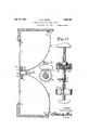
and is intended to open and close the doors motors. 1 I V H The closed doors arelocked by the top bolt 33 engaging thelintel 7 and slidable. in the to the door. There is a similar bolt'36 guidedin thebrackets 37, 38, which engages the floor 8, to lockthe door'at the-bottom;
These bolts '33, 36 are pivoted on the opposite ends of the walking beam- 39, which 1s .two" doors :1, motors.
' lockedby the expansion of thespring 47 en". circling the bolt 36between the bracket 38 pivoted on the pivot 40 fixedto the door 2. The link 41, pivoted in the extreme end of the beam 39 plvotallyengages,the;end =42 of the bell crank 43,,pivoted at .44 on the bracket.
45 fixed to the door. 2. (See Figures 1,6,
1,:and engages thebell crankl43 to causefthe links 41 tolpullydown on the beam 39 to push the .bolts33, 36 intovengagement-with the lintel 7 and floor 8 to mechanically-bolt the 2 when they. are closed byv the These bolts. are held normallynmv and the-set .collar' 48.- v
The door 1 is locked to door 2 by theelec tric and'key operatedlock 49. 1
The doors are closed by the normal rotationof the motors 18, 19 clockwise. Whenthese motorsarei reversed the upper portions of' the-pinions;24- 24 enmeshed "with their respective'segments 9, 16, feniculate ortravel on these segmentsfto, pull the doors open. The
door l-is timed. slightly in advance to open firstwand close last. When the door l'opens ,Thisreleases it'withdraws the bracket 46 (see Figure-8) whichreleasesthe bolts 33,36 which arewithdrawn by the expansion of the spring 47 both doors from they lintel andthe floor so that they may be swungopen by the action of their respective motors'18, 19.7 7 When the 'doorsrea'ch the fully openpositions, the trips 50,51. trip'the :pawls 2' 7, then engaged, releasing the-engagement ofthe driving discs 2 525 from furtherrotation of i the'pinions 24+24inlthe opening direction,
simultaneously with, the full openingwf the;
doors andthe disengagement oftheir driving.
. 52, 53, trip the with the teeth of'the pin- "motors from ion 24 by the springs 30,. 31, respectively,
This motordrive is the same on both doors The angular bracket. 46 is fiXQd OH thG door clutches, as described, the current is switched.
OE and the motors stopped.
Contrawise when the current is reversed through the motors they operate contra-clockwise, with the pawls 26- 26 in engagement with the pinions 2424;to cause them to roll along the segments 9, 10, to closethe doors.
When the doors are fully closed thetrips pawls 26-26 out of engagement with thefpinions 24+24 to declutch the Declutchingthe motors, as described, pro-j teots them from being burnt out, should the automatic .switchesfail to operate, aswill hereinafter be more fully described.
The opening and closing stations orremote control of thedoors, consistofpairsiof insulatedLplates; .of ample, area, A 13, C.-D, EF, see Figure 14.
cuits so that they may beoperatedlonlower voltage forobvious reasons.- The motorcircuit may be 110, 220' or other, appropriate voltage,,and the control .circuit may be trans v ry O her: source-of current-E formed therefrom to 6 volts-or be onseparate urther push on the. doors in y the closing direction, simultaneously with I the opening of the motor circuits;
I These'control circuits" f are preferably separate fromthemotor cir-;
For opening the doors. of garages," fire houses, and thelike, wherein vehicles are stored, the vehiclesare provided with .door
opening controls. (See Figures 9,-10',1l; ,7 The'underside of the floor boards of the vehicle is provided with; the brackets 545-54 whic ppo he casings ..i wh h n turn, providebearings for} the transverse" shaft 56. The -push-.- pedal 57 projectsup wardthroughthefioor,board 58 withincon- V ven-ient reach. offthe heel of the driver of Therewind. spring GO 'has one end r to the shaft 56 and the other; fixed-tothe V adj acent casingl'55, to rewind the shaft after the thrust of e pedal '57.
he-irack teeth 60, enmeshed with the pinion 61-, fixed on the-shaft56,
Suitable drumsare fixed to the' sh-laft'56 within the casings 5555 to which one of the ends of thechains 62, 63 are fixed, so that. i
the chains wind or unwind'as:the'shaft' 56 is rotated.
Pushing the remotej control pedal down unwinds these chains, which descendthrough theCaSingS-at 6 n i t y r p n e tact platesfas at A-"-B. This closes'the ac tuating circuit through the; chain '62 back to the chain 63 ,whichis grounded in the auto- 7 mobile battery control; circuit (see Figure 15,) until the pedal is releasedand the spring '60 rewinds the ch ins and opens the circuit.
Closing the.circuitasdescribed causes curg by shortening the plates AB, since there is rename rent to'fiow from the battery 65, across the switch 66, to the chain 62, to the plate A (see Figure 15.) From A it flows over the line 66 through the magnet 67, thence over theline 68. to the plate B and over the grounded line 69 back to the battery 65.
Energizing the magnet 67 (see Figures 12,
13, 14:) attracts the armature 70 mounted on the dielectric bar 71, which closes the three pole contacts on the open side of the magnetic switch G. This permits the current to flow from the generator 72, over 73 to 741,;
through the magnetic field 75, 76 of the motors 18, 19 in the opening direction, thence over 77 across the G'switch contacts 78, 79 to 80, thence back to the generator. From the generator 72 over 73, the current also passes from contacts 81, 82 of G to 83,
through the armatures 84, 85 of the motors 18, 19, to 86, across contacts 87, 88, 78, 79 to 80 and thence back to the generator 72. i
, The magnetic latch 49 is in a shunt circuit 89, 90, 91 with the opening magnet 67, to release the latch 49 simultaneously with the closing of the G switch. 7
Thus utilizing the automobile battery 65 makes it impossible to open the doors 1, 2
no other source of power in the AB circuit.
The motors 18, 19 will continue to tunetion in the generator motor circuit until the doors 1, 2 are fully open and the trips 50, 51 have tripped their respective clutches out of engagement, as described.
The plates 0-D are located within the garage. .The automobile is driven into the garage as soon as the doors arefully open.
across G to 88, 78, 97, 80 and back to the generator 72. v
The motors are thus reversed by reversing the directionof the current flow through their armatures. The motors continue to operate to fully close the doors, until declutched by the trips 52, 53
The motors 18, 19 may be separately wired to the magnetic switch. In this case, the switch contacts may be timed so that the motor 19 receives current slightly ahead of the motor 18 to insure the proper functioning of the latch mechanism.
When the doors are fully closed the pedal 57 is released and the chains 62, 63 raised from contact with the plates CD by the rewind spring 60', as described.
If it is desired to. operate" the doors: l-Ild$- pendent of the automobile, they] can. be;
opened by closingthe switch 98. The cur rent. then flows from. the.v battery 99;- across switch 98 to 89, through the latch 49,, and
magnet, 67, thence over and 91 backtothe battery. .Energizing the open magnet 67 Closes themotor circuit toyopen the doors; as
previously described.
The operation isreversed by closing. the. switchlOO. The current then flows. from.
the battery 99 across. the switch 10.0; to: 92,;
through the close magnet 93 to 101,.backto the battery 99; Operating the, mag-net 9.3.
reverses the current through the motorgcircuitto close the doorsas described- The key switch 103 is mounted on the out-, side of the. doors and.v is connected: in parallel: with the opening switch 98. The doors may thus be; conveniently opened from the outside by closing; the key switch. Current, their flows fromjthe battery 99 across theswitch 103 to: 89 and, energizes the. open magnet.
to open the doors. 1
This key switch could, also beintroducedinto thejmotor circuit instead, if preferred. A transformer could be substituted for the; battery 99, and its circuits thus operated; elf: the motor circuit or other source ofjavailable current. 77 M I When the car is-backed out; ot the garage,
olt theplates C-D, the. pedal57i is depressed so that the chains 62,-63- will contact the plates EF, outside the garage doors.
The currentfiows' from the battery 65', over; switch 66 to plate; E, thence over 104,101, magnet 93, to plate F, thence over chain 63,
and ground to the battery 65, thus closing V the switch G to actuate the motor. circuit to close the doors 1, 2, from the automobile.
There are three distinct electric circuits.
The remote control circuit energized by the,
actuate or close the motor circuit selective-1y through the magnetic switch G; and the motor circuit energized by thegenerator72. The remote; control and actuating circuits are one in effect. i r o Having thus; described thisinvention what is claimed and desired to. scc ure'by- Letters. Patentisz' f 1. In combination with. a? pair of hinged doors; arcuate rack segments fixed relativeto.
the hinge centers of said doors tripsat, the
ends of said segments; an xe-lectric circuit,'re-
actuatingcircult energized by the batteries6 5, or- 99,- to
versible motors on said doors engaging said segments, and a reversible switch in said cirg 'cuit; a remote control for said switch; and clutches interposed between said motors and segments and engaging said trips.
" 2. In combination with a door, an electric 1 motivecircuit, motive means in said circuit adapted to open and close said doors, a reversing switch in said motive circuit, an open actuating circuit controlling said switch and having apair of spaced contact plates, flexible contacts in a vehicle battery circuit adapt ed to makeconta'ct with said plates'to close said actuating circuit, and means for withdrawing said flexible contacts from saidplates. V
,3. In combination with a door, an electric motive circuit, motive meansin-said circuit ing switch in sald motive circuit, an open adapted to open and close said door, a revers actuating circuit controlling said switch for the opening of said door and havlng a pair I p of spaced'contact plates, a second open actuating circuit controlling said switch for the closing of said door, contacts in a vehicle battery" circuit adapted to make contact with either pair of contact plates to close said actuating circuit.
4: In combination with a door, an electric circuit, a reversible motor insaid circuitand mounted on said door, a segment fixed "to the frame of the door relative to the hinge centers ther-eofand engaged by said motor, a trip at each end of said segment, a clutch interposed between said motor and segment and having a-pawl adapted to be released by said trips. 7 r 7 5.111 combination with a pair of doors hinged in a door frame, an electric motive, circuit, motive means in saidcircuitfor open- 'ing and closing said doors,a bolt on one of said doors adapted to engage said door frame hinged in'a door frame, an electric motivecirv ment with said doorframe against the ten- I when closed. 1 o 1 In testimony whereof I have hereunto? when said door is closed, a bell crank con- I :nected to said bolt,'a bracket mounted on the second door and adapted to engage sai'd'bell crank when the doors are closed to force said boltinto engagement with said door frame, and a latch for locking the two doorstogether when closed; 7
6.'In combination with a pair of doors cuit, ,mot1ve means in said circuitfor opening and closing sald doors, a bolt on 'one'oi' said doors adapted, to engage said door frame whensaid door is closed, a spring urging said bolt out of engagement withsaid door frame, a bell crank connected with said bolt, a
bracket mounted on the second door and adapted to engage said bell crank when the, doors'are closed to force-said bolt into engages sion of said spring and an electrically operated latch for locking aifixedmy signature. V
1 o FRANK NUNEZ;
two doors together
Priority Applications (1)
| Application Number | Priority Date | Filing Date | Title |
|---|---|---|---|
| US396221A US1868149A (en) | 1929-09-30 | 1929-09-30 | Automatic door opener and closer |
Applications Claiming Priority (1)
| Application Number | Priority Date | Filing Date | Title |
|---|---|---|---|
| US396221A US1868149A (en) | 1929-09-30 | 1929-09-30 | Automatic door opener and closer |
Publications (1)
| Publication Number | Publication Date |
|---|---|
| US1868149A true US1868149A (en) | 1932-07-19 |
Family
ID=23566352
Family Applications (1)
| Application Number | Title | Priority Date | Filing Date |
|---|---|---|---|
| US396221A Expired - Lifetime US1868149A (en) | 1929-09-30 | 1929-09-30 | Automatic door opener and closer |
Country Status (1)
| Country | Link |
|---|---|
| US (1) | US1868149A (en) |
Cited By (5)
| Publication number | Priority date | Publication date | Assignee | Title |
|---|---|---|---|---|
| US2668052A (en) * | 1950-01-13 | 1954-02-02 | Paul S Johnson | Maximum security door |
| US2755081A (en) * | 1951-10-08 | 1956-07-17 | Johnson Clarence | Garage door operators |
| US2865629A (en) * | 1955-06-07 | 1958-12-23 | Herring Hall Marvin Safe Compa | Automatic door system |
| US20050066829A1 (en) * | 2003-09-26 | 2005-03-31 | John Cogswell | Hinge system for mounting a servo-motor |
| US8225458B1 (en) | 2001-07-13 | 2012-07-24 | Hoffberg Steven M | Intelligent door restraint |
-
1929
- 1929-09-30 US US396221A patent/US1868149A/en not_active Expired - Lifetime
Cited By (8)
| Publication number | Priority date | Publication date | Assignee | Title |
|---|---|---|---|---|
| US2668052A (en) * | 1950-01-13 | 1954-02-02 | Paul S Johnson | Maximum security door |
| US2755081A (en) * | 1951-10-08 | 1956-07-17 | Johnson Clarence | Garage door operators |
| US2865629A (en) * | 1955-06-07 | 1958-12-23 | Herring Hall Marvin Safe Compa | Automatic door system |
| US8225458B1 (en) | 2001-07-13 | 2012-07-24 | Hoffberg Steven M | Intelligent door restraint |
| US9121217B1 (en) | 2001-07-13 | 2015-09-01 | Steven M. Hoffberg | Intelligent door restraint |
| US9995076B1 (en) | 2001-07-13 | 2018-06-12 | Steven M. Hoffberg | Intelligent door restraint |
| US11187022B1 (en) | 2001-07-13 | 2021-11-30 | Steven M. Hoffberg | Intelligent door restraint |
| US20050066829A1 (en) * | 2003-09-26 | 2005-03-31 | John Cogswell | Hinge system for mounting a servo-motor |
Similar Documents
| Publication | Publication Date | Title |
|---|---|---|
| US4121382A (en) | Mechanized door operating means for a motor vehicle | |
| US4624491A (en) | Electrically-opened latch, in particular for motor vehicle doors | |
| US2124037A (en) | Vehicle window control mechanism | |
| US2758836A (en) | Door-operators | |
| GB1408665A (en) | Door operator with door panel position sensing and locking device | |
| US1868149A (en) | Automatic door opener and closer | |
| US2020831A (en) | Overhead door | |
| US3224493A (en) | Door and control system therefor | |
| US1151479A (en) | Electric door unlocking and opening and closing means for automobiles. | |
| US3271901A (en) | Jail door operator | |
| EP0417138B1 (en) | Opening mechanism for door closer | |
| US2661945A (en) | Electric door operator | |
| US1755788A (en) | Garage-door opener | |
| GB2167120A (en) | Remote power operated rear window device | |
| US1878796A (en) | Automatic door | |
| US1874903A (en) | Closure operator | |
| US2696981A (en) | Combined door and window regulating system for motor vehicles | |
| US3763594A (en) | Doors with electro-mechanical operating means | |
| US2218505A (en) | Door operating mechanism | |
| US3104098A (en) | Door operator | |
| US2009342A (en) | Elevator door control | |
| US2961076A (en) | Master actuating mechanism for operating cell doors and keyless locks | |
| CN208167600U (en) | A kind of remote control parking spot lock device | |
| DE447234C (en) | Safe door | |
| US3438148A (en) | Door operator |