US1859924A - Call charging telephone exchange system - Google Patents
Call charging telephone exchange system Download PDFInfo
- Publication number
- US1859924A US1859924A US464442A US46444230A US1859924A US 1859924 A US1859924 A US 1859924A US 464442 A US464442 A US 464442A US 46444230 A US46444230 A US 46444230A US 1859924 A US1859924 A US 1859924A
- Authority
- US
- United States
- Prior art keywords
- relay
- contact
- circuit
- cam
- winding
- Prior art date
- Legal status (The legal status is an assumption and is not a legal conclusion. Google has not performed a legal analysis and makes no representation as to the accuracy of the status listed.)
- Expired - Lifetime
Links
Images


Classifications
-
- H—ELECTRICITY
- H04—ELECTRIC COMMUNICATION TECHNIQUE
- H04Q—SELECTING
- H04Q3/00—Selecting arrangements
- H04Q3/42—Circuit arrangements for indirect selecting controlled by common circuits, e.g. register controller, marker
Definitions
- This invention relates to dial telephone systems and more particularly to metering calls on multi-party telephone lines.
- the ob ect of the invention is the attainment of more equitable compensation for the use of telephone facilities.
- each line finder of the group which has access to a group of 400 subscribers lines is paired with a district selector by a link circuit.
- zone recording relays which are selective- 1y operated from the common register sender in accordance with the zone of the exchange area into which a connection is extended.
- the sequence switch of the district selector also assumes different positions dependent upon the zone into which the connection is established and cooperates with the zone recording relays to establish in the timing switch circuit a record of which of six zones the called line terminates in.
- a message register connector circuit is provided. This common circuit is equipped with a plurality of sets of multi-contact relays, each set serving to connect with all of the message registers of corresponding party stations.
- one set of relays is arranged to connect with all of the registers of the J stations and the other set of relays is arranged to connect with all of the registers of the stations of the group of 400 lines.
- Associated with the common connector circuit is a plurality of party designating relays which are selectively operated-from the line finder-district link for operating the multicontact relays in accordance with the test made by the link for determining which party on a calling line has initiated a particular call.
- the common connector circuit is also provided with a group of zone recording relays to which the zone record 1s transferred from the timing switch circult and which control, through an impulsing device, the application of one or more impulses to the party line message register selected. These impulses are applied through the line finder-district link over a line finder brush to the message register terminal of the calling line.
- the invention functions in the following manner: After the calling subscribers line has been extended to the line finderdistrict link by the line finder, a test is made to determine which party on the line has initiated the call and a. record of such test is made in the link.
- the timing switch functions to cause the association of the common message register connector circuit with the link and to transfer the zone record which has been set up in the timing switch circuit through the operation of the sender and district selector sequence switch to the zone recording relays of the common circuit.
- the party designation is at this time also transferred from the link to the common circuit.
- the common register connector circuit thereupon proceeds through the operation of its multi-contact relays to connect with the terminals of all message registers of the group of 400 lines in which the calling line is located corresponding to the party on the calling line who has initiated the call and to establish a.
- message register operating circuit extending from operating battery through the link circuit over a brush and terminal of the line finder to the other terminal of the message register of the calling line party. Since the line finder can connect with but one register terminal at a time, an operating circuit for only the register of the calling line substation is effective.
- the selected message register is variably operated to charge thev calling party for the initial period of conparty register to charge for an overtime period of conversation.
- the timing-switch is advanced to dismiss the common circuit and to measure off a second period for conversation. In this manner the timing switch advances through successive cycles until the connection is released.
- the overtime periods measured vary in accordance with the zone in which the called line terminates-and differ from the initial period measured on the same call.
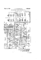
- Fig. 1 shows a calling subscribers line having two party substations thereon together with certain relays common to groups of callinglines;
- Fig. 2 showsa start circuit and a of two link circuits
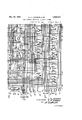
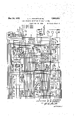
- Figs. 3 and 6 taken togetherv show a line finder-district link circuit, Fig. 3 showing the line finder and Fig. 6 the district selector;
- Fig. 4 shows'a link circuit for associating a sender with the district selector
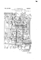
- Fig. 5 shows a skeletonized disclosure of a register sender
- Fig. 7 shows in schematic form selectors for completing a connection to an automatic subscribers line, to a manual oflice or to an operators position;
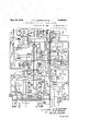
- Fig. 8 shows a timing switchindividual to the line finder-district selector link of Figs. 3 and 6 for measuring the initial and overtime periods of conversation allotted to a calling subscriber for calls to different zones of the exchange area, and for seizing the common message register connector circuit;
- Figs. 9 and 10 taken together show a common message register connector circuit for connecting the message register of a calling party line substation into an operating circuit and for controlling the manner in which the connected message register shall .be operated for calls to different zones;
- Fig. 11 shows the manner in which Figs. 1 to 10 should be .arranged to completely disclose the invention.
- the timing switch is advanced to dismiss the common circuit and under the control of a timing interrupter to measure off a period of time prescribed for the initial period of conversation, which period may differ in accordance with the zone of the exchange area into which the connection has been extended. If the conversation continues at the end of this period, the timing switch is caused to start upon a second cycle, again seizing the common register connector circuit and causing the operation of .the calling closure which is similar to that of U. S. Patent 1,567,072, granted'to W. H.
- a plurality of link circuits isarranged to serve a group of calling lines'and are taken into service in rotation.
- a link circuit completes its function it hunts for and associates itself with a district selector which is ready for use and the link and district remain in a sub-allotted condition until the next l nk inthe series has been put into service.
- the link circuit is then put into an allotted position from whichit'will be advanced by the initiation of a call and the action of the start circuit of Fig. 2.
- Establishment of a connection from substa- V at substation J first initiates a call for line 700 in zone 5 of the exchange area for which he is to be charged five times for the' first three minutes of 'conversationand once for each one minute overtime period of conversation.
- the subscriber at substation J removes his receiver from the switchhook a circuit is closed from battery through the winding of relay 101, back contact of relay 102, over the subscribers line to ground at the outer contact of relay 102.
- Relay 101 in operating closes a circuit from battery, winding of relay 103, right back contact of relay 104 to ground at the outer front contact of relay 101.
- Relay 103 in operating closes a circuit from battery over the back contact of relay 201, conductor 130, right winding of relay 108, inner back contact of relay 107, back contacts of relay 109, middle left contact of relay 103 to ground. 7
- Relay 108 operates in this circuit and closes a locking circuit for itself from battery through the right winding of relay 201, conductor 129, over back contacts of relays similar to relay 108 individual to other groups of lines appearing before the same line finder, inner left front contact and left winding of relay 108, the right back contact of relay 109 to ground at the middle left front contact of relay 103.
- Relay 108 prepares a circuit from groun at its outer right contact through the winding of trip magnet 303 of the line finder to battery in preparation for tripping the proper set of brushes when the line finder is operated.
- Relay 201 operates in the locking circuit of relay 108 and in combmation therewith closes a circuit from ground over its outer right contact, conductor 128, inner right contact of relay 108, winding of relay 110 to battery.
- Relay 110 locks over its inner right contact, the left back contact of relay 109 to ground at the middle left front contact of relay. 103.
- Relay 110 closes a starting circuit for the allotted line finder.
- sequence swltch 400' willbe standing in position 1 and sequence switch 600 in position 2.
- the op eratlon of relay 110 will therefore close a. circult from ground at its outer right contact, outer left front contact .”of relay 108, inner left front contact of relay 103, conductor 131, left back contact of relay 202, inner left back contact of relay 203, conductor 206, upper left and lower right contacts of cam 403, brush 402 and terminal 401, conductor 378,
- Relay 302 upon operating, closes a circuit from battery through the winding of updrlve magnet 304 of the line finder, outer right contact of relay 302 and in parallel through the winding of relay 300, upper contacts of cam 603, inner left front contact of relay 302 to ground at the lower left contact of cam 604.
- Relay 302 also locks over its inner right front contact, the upper left and lower right contacts of cam 605, the back contact of relay 305 to ground over commutator segment 306 and brush 307.
- the line finder moves upwardly under the control ofmagnet 304 and since trip magnet 303 is operated, the proper set of brushes is tripped.
- relay 300 removes ground from the line finder brush 326 during hunting, and prepares a circuit which is closed as soon as commutator brush 308 engages segment 309 which extends from ground on brush 308, outer left contact of relay 300, conductor 404, contact 230 of key 204, inner right front contact of relay 201 to conductor 129 and the right. winding of relay 201. This circuit shunts the winding of relay 108 and causes that relay to release, in turn, releasing the trip magnet 303. W hen the brush 308 leaves segment 300 the circuit of relay 201 is opened and that relay also releases.
- This shunt circuit reduces the resistance in series with the winding of marginal relay 109 sufficiently to cause .that relay to operate and to open the locking circuit of relay 110 which, in turn, opens the energizing circuit of relay 302.
- the operation of relay 305 also opens one locking circuit of relay 302 causing that relay to release as soon as the line finder brushes become centered on the terminals of the calling line and commutator brush 314 engages an insulating portion of centering segment 315.
- the release of relay 302 opens the circuit of updrive magnet 304 to arrest the hunting movement of the line finder and opens the circuit of relay 300.
- relay 300 At the time relay 300 operated it closed a circuit from ground at its inner left contact over conductor 379, terminal 407 and brush 406 of finder 410, lower contact of cam 408, winding of relay 409, resistance 411 to battery.
- Relay 409 operates and-closes a circuit from battery through the winding of sequence switch magnet 400, upper contact of cam 412 to ground at the outer left front contact of relay 409, advancing the link sequence switch 400 to position 2.
- relay 409 releases.
- a circuit is closed from battery, through the winding of relay 413, the upper contacts of cam 414, right back contact of relay 415 to ground at the lower right contact of cam 416.
- Relay 413 operates closing a circuit from battery through the left winding of relay 417, left front contact of relay 413 to ground at the left back contact of relay 415.
- Relay 417 in operating, closes a circuit from battery through the winding of updrive magnet 418 of the sender finder 420, left contact of cam 479, outer right front contact of relay 417 to ground at the left back contact of relay 409.
- the sender finder moves upwardly under the control of magnet 418 in search of an idle sender.
- Relay 413 also closes a circuit from battery through the right winding of relay 415, the upper right and lower left contacts of cam 421, middle winding of relay 415 to ground at the right contact of relay 413.
- the current in this circuit is not sufficient to operate relay 415 but does create a flux in its magnetic circuit so that it becomes quick to operate when the test circuit is later closed.
- the test circuit extends from brush 422, over the lower contacts of cam 419, the right back contact of relay 409, the left winding of relay 415, the lower contacts of cam 421, middle winding of relay 415 to ground at the right contact of relay 413.
- An idle sender is characterized by battery connected to conductor 502.
- brush 422 engages terminal 423 corresponding to the sender of Fig. 5 which is assumed to be idle
- the test circuit above traced is completed over terminal 423to battery and relay 415 operates quickly.
- Relay 415 in operating, closes a locking circuit for itself from battery, through its right winding, upper right and lower left contacts of cam 421 to ground at the left front contact of relay 415. It also opens the circuit of re-' lay 417 which releases to, in turn, release magnet 418 and bring the sender finder to rest on the terminals of the idle sender. The release of relay 417, in turn, releases relay 413.
- a circuit is now established for advancing sequence switch 600 into position 3 which may be traced from battery through magnet 600, the lower right contact of cam 612, the left front contact of relay 318, conductor 319, lower contacts of cam 807, conductor 808, the left back contact of relay 302 to ground at the lower left contact of cam 604. 5 As the sequence switch 600 advances from position 2 to 3, relay 318 releases. l Vith sequence switch 600 in position 3, busy ground is applied to the sleeve conductor 112 of the calling line over line finder brush 326, right back contact of relay 300, resistance 317, inner lower back contact of relay 316 conductor 812 to ground at the upper left contact of cam 607.
- Cut-off relay 102 of the calling line operates over this circuit releas- 115 ing line relay 101 which,-in turn, removes battery from conductor 114, thereby releasing relay 305.
- sequence switch 600 With sequence switch 600 in position 3 a circuit is established from battery through the winding of relay 322, resistance 323, lower right contact of cam 601, upper right contact of cam. 602, segment 335 and brush 336 to ground for testing the sensitivity of test relay 322.
- Relay 322 should operate at this time and upon operating establishes a circuit for relay 324 extending from battery through the winding of relay 324, outer left back contact of relay 325 to groundat the contact of relay 322.
- Relay 324 upon operating looks over. its inner right relays 316 and 329, brush 334, terminal 333,
- ⁇ Vhen sequence switch 400 reaches positlon 3 a circuit is closed from ground through the left and middle windings of relay 503, back contacts of relays 504 and 505, conductor 506, terminal 430. brush 431. right contact of cam 434, brush 432, terminal 433, conductor 314, lower leftand upper right contacts of cam 613, assuming that the district selector sequence switch 600 has new advanced to posltion 3, through the winding of relay 351 to battery and in parallel over the lower contacts of cam 613 to battery through the lower winding of relay 316.
- Relay 316 is marginal and does not operate but relay 315 operates although ineffective at this time.
- Relay 503 operates and closes an obvious circuit for relay 507 which, in turn, closes a circuit for relay 509.
- Relay 509 operates relay 510.
- sequence switch 400 arrived in position 2 it prepared a pulsing circuit for receiving dial pulses.
- This circuit may be traced from battery through the left winding. of relay 500, conductor 537, terminal 440, brush 441,- lower contacts of cam 429, brush 47 8, terminal 477, conductor 375, left contact of cam 615, upper back contacts of conductor 116, through the subscribers substation conductor 117, terminal 332,.
- Relay 500 operates in turn operating relay 518 in the well-known manner, relay 518, in turn, operating relay 519.
- a circuit is thereupon closed from the source of tone 516 through the right winding of relay 500, switch 520 in normal position, front contact of relay 519, contact of cam 514 to ground at the front contact of relay 509.
- This tone is transmitted to the calling subscriber to inform him that the sender is ready to receive impulses which he may then send by manipulating his dial.
- ⁇ Vhen relay 510 operated it removed battery from conductor 502releasing relay 415.
- ⁇ Vith relay 415 released a circuit is closed from battery, through the winding of sequence switch magnet 400, upper left contact of cam 476, right back contact of relay 415 to ground at the lower right contact of cam 416 for advancing sequence switch 400 into position 5.
- Sequence switch 400 remains in position 5 throughout the further operation of the sender.
- the calling subscriber now proceeds to dial the desired line number for setting the registers and translator of the sender in the well-known mannerr
- the switch After dialing the first digit the switch, the wlper of which is shown at 520, advances from normal closing a circuit extending from battery through the winding of relay 517, terminals and wiper 520, contacts of relay 519, contact of cum 514 to ground at the outer right contacts of earn 509.
- Relay 517 closes an obvious circuit for relay 521.
- the translator is set in a manner described in the aforementioned patent to O. H. Kopp.
- 're-' lay 533 operates and circuits are prepared over the translator are 534, through a back contact of relay 535 for operating either relay 536 or relay 547 .or neither of them dependent upon in which zone of'the exchange the wanted line is located. For example, vif a called number isvdialed for either zone 0 or zone 1, neither relay 536nor 547 will be operated.
- relay 536 will be operated and if the call is for either zone 4 or zone 5, relay 547 will be operated. It will be assumed that a call is for a subscribers line terminating in the fifth zone and that therefore relay 547 is operated over a circuit extending from battery, winding of relay 547, back contact of relay 535, translator are 534 to ground at the contact of relay 533.
- Relay 547 locks over its left front contact, the contact of cam 514 to ground at the outer right front contact of relay 509 and extends its locking ground to the winding of relay 538.
- Relay 538 upon operating establishes a circuit from ground at the outer right contact of relay 509 over the contact of cam 514, the contact of relay 538 to battery through the winding of relay 535.
- Relay 535 operates opening the initial energizing circuit of relay 547 and connecting the translator are 534 over a cable 539 to the class switch 540, which is diagrammatically indicated in the upper right portion of Fig. 5.
- the class switch is thereupon set from the are 534 of the translator.
- relay 318 With sequence switch 600 in position 3 relay 318 is energized over a circuit extending from battery through its right winding, the lower right contact of cam 610, the lower left contact of cam 611, conductor 378, terminal 401 and brush 402 of district finder 410, the left contacts of cam 435, brush 436 and terminal 437 of sender finder 420, conductor 542, the contact of relay 521, the back contact of relay 504, right contact of cam 526, Winding of sender stepping relay 522, back contact of counting relay 525, left winding of overflow relay 523, left contact of cam 527, resistance 530 to ground.
- Relays 522 and 318 operate, relay 318 looking over its inner right front contact, the upper left contact of cam 610, thence over the circuit traced, whereby it remains energized as the sequence switch 600 advances into position 4.
- Relay 318 also closes a circuit to advance sequence switch 600 into position 4, extending from battery through the winding of magnet 600, lower right contact of cam 608, the outer right front contact of relay 324, the left front contact of relay 318, conductor 319, the lower contacts of cam 807, conductor 808, left back contact of relay 302 to ground at the lower left contact of cam 604.
- relays 322 and 324 release.
- the district selector is now controlled by the sender in its brush and group selection movements and then proceeds to hunt for an idle trunk in the Well-known manner. After an idle trunk is selected a circuit is established in position 9 of sequence switch 600 for relay 318, extending from battery through its left winding, the lower contact of cam 618, the lower left contact of cam 601,
- reversed battery from the incoming selector 701 operates relays 522 and 523 in the usual manner and these relays, in turn, cause the operation of the relays 531, 524 and 504. lVith these relays operated, the sender sequence switch is advanced to position 18 for controlling talking selection.
- Relay 315 is operated in parallel with the lower winding of relay 316 throughout selections.
- the operation of relay 504, above mentioned, now opens a shunt around the right winding of relay 503 including that winding in the circuit of relays 351 and 316.
- Relay 35 1 thereupon releases, in turn, opening the circuit of relay 318 which also releases.
- the district sequence switch 600 Upon the release of relay 318 the district sequence switch 600 is advanced into position 11 over a circuit extending from battery, winding of magnet 600, upper left contact of cam 608, left back contact of relay 318, thence as traced to ground at the lower left contact of cam 604.
- ground is connected to conductor 314 at the lower right contact of cam 617, over terminal 433, brush 432, upper contacts of cam 446, left winding of relay 415, right back contact of relay 409, lower contact of cam 434, brush 431, terminal 430, conductor 506, left back contact of relay 505, windings of relay 503. Since these windings are also connected to ground, relay 503 now releases, in turn, releasing relay 507.
- the release of relay 507 does not release relay 509 since that-relay is locked to its own front contact. A circuit ft contact to conround as above traced.
- sequence switch 600 With sequence switch 600 in position 11 the subscribers line becomes disconnected fromthe sender at contacts of cams 615 and 617 and relay 329 is operated in a circuit extending from battery, through its upper winding, the upper back contact of relay 330, the lower right and upper left contact of earn 619 to ground at the upper right contact of cam 617.
- Relay 329 upon operating extends its operating circuitover its middle upper front contact to battery through the winding of relay 338 which operates.
- relay 338 connects the winding of relay 322 to the tip-and ring conductors 116 and 117 of the calling line, and establishes a holding circuit from ground at its middle left contact through the lower winding of relay 329 to insure that rea lay 329 will remain operated until after relay (iii 338 has released to disconnect relay 322 from conductors 116 and 117.
- relay 329 operated the operating ground therefore is also connected to the cam Contact of interrupter 339 and thence as soon as interrupter 339 closes its lower contact to battery, through the right winding of relay 340.
- Relay 340 operates and locks over its inner right front contact to the operating ground independently of interrupter 339 and as soon as interrupter 339 makes its upper contact, establishes a circuit for relay 302 extending from battery through the winding of relay 302, middle right front contact of relay 338, outer rightfront contact of relay 340, upper contact of interrupter 339, thence to ground as traced at the upper right contact of cam 617.
- Relay 302 upon operating locks over its inner right front contact to ground at the lower front contact of relay 329 and at its inner left front contact establishes a circuit for advancing sequence switch 600 into position 12.
- This circuit extends from battery through the winding of magnet 600, the upper left contact of cam 612, conductor 620, the upper right and lower left contacts of cam 801, conductor 802, the inner left front contact of relay 302 to ground at the lower left contact of earn 604.
- the operating circuits of relays 329 and 338 and the holding circuit of relay 340 are "opened and relays 338 and 340 release.
- relay 324 upon operating, operates relay 324 which then looks over its inner right front contact to ground at the lower left contact of cam 617, registering the fact that the party W has initiated the call.
- a circuit is also established for relay 318 extending from battery through its right winding, the lower right contact of cam 610, lower left contact of cam 611, conductor 378, terminal 401, brush 402, left contacts of cam 435, brush 436, terminal 437, conductor 542, front contact of relay 521, front contact of relay 504, right contact of cam 526, the sender sequence switch being in position 18 for talking selection, windings of relays 522 and 523, right contact of cam 527, right back contact of relay 507 to ground through resistance 530.
- Relays 318 and 522 energize relay 318 closing a circuit extending from battery through sequence switch magnet 600, the lower right contact of cam 612, the left front contact of relay 318, thence to ground at the lower left contact of cam 604, as previously traced.
- Relay 318 upon energizing, locks over its inner right front contact, the upper left contact of cam 610, thence over the fundamental circuit as traced.
- sequence switch 600 rotates out of position 12 toward position 16
- ground is intermittently connected to the fundamental circuit in shunt of sender stepping relay 522 over the upper contacts of cam 606.
- the fundamental circuit is opened at the sender through the operation of relay 525.
- Relay 318 deenergizes arresting sequence switch 600 in its next stopping position,
- the sequence switch may be arrested in any one of three positions, position 13, which is a charging po sition for connections to zones 0, 2 and 4, po-
- - sition 14 which is a charging position for connections to zones 1, 3 and 5 and position 15 for connections to an operators position. Since it has been assumed that the calling subscriber has made a call to zone 5 of the exchange, the district selector sequence switch will be arrested in talking selection position 14.
- relay 515 operates connecting battery to conductor 506 in parallel with the winding of relay 505.
- the current in this circuit is now suificient to operate relaiy 415 which closes a circuit from battery through the left winding of relay 417, left contacts of cam 421 to ground at the left front contact of relay 415.
- Relay 417 closes a circuit from battery through the winding of sequence switch magnet 400, upper contact of cam 479, outer right front cont-act of relay 417, left back contact of relay 409 to ground, advancing sequence switch 400 to position 6. In this position all the conductors extending to the sender are opened and the sender is completely released.
- relay 415 releases and, in turn, releases relay 417 unless the sender finder 420 is standing on one of its top ten terminals. If the latter condition exists relay 417 is held operated in a circuit from battery over its left winding and left front contact, upper left contact of cam 424, commutator segment 464, brush 463 to ground. With relay 417 operated at this time a circuit is closed from battery through resistance 411, winding of relay 409, lower contact-s of cam 414, inner right front contact of relay 417, lower right contact of cam 416 to ground. Relay 409 looks through its inner left contacts to ground at the lower confacts of cam 467 and also closes a second locking circuit for relay 417.
- lVith relay 409 operated a circuit is closed from battery through the winding of downdrive magnet 465 of the sender finder 420, left contact of cam 412 to ground at the outer left front contact of relay 409.
- a circuit is closed from ground, over brush 463, bottom commutator segment 406, lower right contact of cam 456 to resistance 411. shunting the winding of relay 409 and causing that relay to release, in turn, releasing relay 417.
- relay 417 released in position 6 a circuit is closed from battery through the winding of sequence switch magnet 400, lower right contact of cam 476, right back contact of relay 417 to ground at the lower right contact of cam 416, advancing sequence switch 400 to position 7.
- sequence switch 400 When sequence switch 400 reaches position 7, thelink circuit is ready to associate itself with another district selector which is standing in position 1 awaiting association. with a link and a circuit will be closed from ground over the upper right contact of cam 617, the
- Relay 413 closes a circuit from battery through the left winding of relay 417, left front contact of relay 413'to ground at the left back contact of relay 415.
- Relay 417 in operating closes a circuit for updrive magnet 447 of the district finder 410, lower right contact of cam 479, outer, right front contact of cuit extends from conductor 366, terminal 450, brush 451, contact of ack 449, upper left and lower right contacts of -cam 419, right back contact of relay 409, left winding of relay 415, lower contacts of cam 421, middle winding of relay 415, to ground at the right contact of relay 413.
- Relay 415 is held operated in position 8 from battery at the district selector over terminal 450, brush 451, contacts of jack 449, upper left and lower right contacts of cam 419, back contact of relay 409, left winding of relay 415, lower contacts of cam 421 to ground at the left front contact of relay 415.
- lVith relay 415 operated a circuit is closed from ground at the right lower contact of cam 416, right front contact of relay 415, the upper left contact of cam 429, brush 47 8, terminal 477, conductor 37 5, upper right contact of cam 611, lower right contact of cam 610 to battery, through the right winding of relay 318.
- Relay 318 operates and closes a circuit from battery through the winding of sequence switch magnet 600, lower right contact of cam 612, left front contact of relay 318, conductor 319, lowergontacts of earn 807, conductor 808, left back contact of relay 302 to ground at the lower left contact of cam 604, sequence switch 600 advancing to position 2, releasing relays 3l8and 415.
- Relay 415 upon releasing, closes a circuit from battery through the winding of sequence switch magnet 400, upper left contact of cam 476, right back contact of relay 415 to ground at the lower right contact of cam 416 for advancing sequence switch 400 to position 9.
- the link circuit remains in this position until the link standing next to it in the series is advanced from position 1 for the purpose of selecting a sender.
- Link circuit 260 occupyingthat relationship to the link circuit of Fig. 4 a circuit may be traced from ground over the lower contact of cam 261, the right.
- relay 627 operates in a circuit which may be traced in part from brush 621, the upper contacts of cam 622, the upper right winding of repeating coil 631, winding of relay 627, lower right winding of coil 631, upper contacts of cam 624, to brush 625.
- relay 627 establishes a circuit from ground at the right contacts of cam 607, front contact of relay 627, upper contacts of cam 623, conductor 628, right contacts of cam 813, conductor 814, lower contact of inter raptor 3-13, conductor 815, upper left and lower right contacts of cam 816, conductor 81.7, left winding of relay 340 to battery.
- Relay 340 operates and looks over the circuit previously traced to conductor 814, thence over the outer left front contact ofrelay 340, conductor 815, thence as traced to battery through the loft winding of relay 340.
- interrupter 343 makes its upper contact, a circuit is established from battery through the winding of sequence switch magnet 800, lower right contact of cam 818, right contacts of earn 819, conductor 822, upper contacts of cam 618, conductor 630, inner left front contact of relay 340, upper contact of interrupter 343, conductor 814, thence to ground as traced over the front contact of relay 627, to ground at the right contacts of cam 607 for advancing sequence switch 800 into position 2.
- the holding circuit of relay 340 is opened and relay 340releases.
- relay 325 extending from battery through the winding of relay 325, conductor 345, upper right and lower left contacts of cam 816, conductor 831, to ground at the lower left contact of cam 617.
- Relay 325 upon operating extends its operating ground to the winding of relay 321 over its inner right front contact, thereby operating relay .321 which looks itself and relay 325 over itainner left front contact to ground at the lower contacts of cam 607.
- sequence switch 800 With sequence switch 800 in position 2, a start circuit is established from ground on conductor 628, over the lower left contact of cam 813, upper winding of relay 823, conductor 824, left back contact of relay 1000, right back contact of relay 1001, right back contact of relay 1002, winding of relay 1003, to battery at the back contact of relay 1004, if the message register connector circuit of Figs. 10 and 11 is at the time free. Relays 1003 and 823 operate and if the timing circuit of Fig.
- relay 823 locks over its lower winding, the left contacts of cam 825, the upper front contact of relay 823, conductor 826, right back contact of relay 1000, winding of relay 1004, to ground at the left back contact of relay 1002.
- Relay 1004 operates in this locking Upon opwinding of relay 1006.
- Relay 827 also operates in parallel with the locking winding of relay 823, extending common operating leads 850 from the connector circuit tothe district;
- relay 900 is operated over a circuit extending from battery, winding of relay 902, winding of relay 900, conductor 903, inner upper from contact of relay, 344, left back contact of relay 324, lower frpnt contact of relay 344, lower contacts of cam 605, commutator segment 335, brush 336 to ground.
- relay 901 is operated from battery, winding of relay 902, winding of relay 901, conductor 904, upper front contact of relay 344, left front contact of relay 324, thence to ground as traced at brush 336.
- Relay 902 being marginal does not operate in the circuit of either relay 900 or relay 901.
- each relay 905 With relay- 900 operated circuits are closed for five multi-contact relays, one of which is shown at 905, and each relay 905 extends its operating circuit to a corresponding multi-contact relay 906.
- Each multi-contact relay such as 905 and 906, controls operating circuits extending to forty message registers, and thus as soon as five relays similar to relay 905 and five relays similar to relay 906 are operated through the operation of relay 900, the message registers of all substations corresponding to the substation J of the 400 lines-appearing in the line finder in Fig. 3 are connected through the contacts of these relays to the corresponding operating conductors of'the 400 lines terminating in terminals corresponding to terminal 380 appearing in the line finder bank.
- the circuit of message register 105 of the calling party J may be traced in part from terminal 380, conductor 114, the back contact of line relay 101, conductor 106, the outer right front contact of relay 905, conductor 907 to ground through message register 105.
- relay 901 operated, in turn operating five multi-contact relays corresponding to relay 908 and in turn five multi-contact relays corelay 1006 does not respondin to relay 909, then the message registers of a l substations corresponding to the substation W of the same 400 lines would be connected to the operating conductors of the 400 lines terminating in terminals corresponding to terminal 380.
- circuit through message reg ister magnet 135 may be traced in part from terminal 380, conductor 114, back'contact of line relay 101, conductor 106, theouter right front contact of relay 908, conductor 910 to ground through 'message register 135.
- Relay 911 operates and remains operated until all of the multicontact relays, such as 905, 906 which should operatehave operated, and at its left back contact opens the operating circuit 'of charging relay 1007 to prevent initiation of charging.
- the marginal relay 902 will receive current to operate and will in turn hold relay 911 operated to prevent charging.
- test circuits extends from battery through the winding of relay 913, winding of zone relay 914, conductor 835, upper front contact of relay 827, left contacts of cam 834, to ground at the inner lower front contact of relay 810 if relay 810 is operated, or over the inner lower back Contact of this relay, the left contacts of cam 839 to ground at the lower front contact of relay 823, if relay 810 is not operated.
- Another circuit extends from battery through the winding of relay 913, the winding of relay 915, conductor 1010, the right back contact of relay 1008, conductor 836, the lower front contact of relay 827, the lower right and upper left contacts of cam' 829 to ground at the upper front contact of relay 809 if it is operated, or if it is not operated over its upper back contact through the left contacts of cam 839 to ground at the lower front contact of relay 823.
- sequence switch 600 is in position 13
- a circuit is established from battery, winding of relay 913, winding of zone relay 912, con ductor 840, inner lower front contact of relay 827, left contacts of cam 842, upper front contact of relay 810, which is operated
Landscapes
- Engineering & Computer Science (AREA)
- Computer Networks & Wireless Communication (AREA)
- Interface Circuits In Exchanges (AREA)
Description
24, 1932- 1.. H. JOHNSON ET AL CALL CHARGING TELEPHONE EXCHANGE SYSTEM Filed June 28, 1950 1O Sheets-Sheet 1 L; hf JOHNSON E 5' 5/as0/v May 24, 1932. L. H JOHNSON ET AL 1,859,924
CALL CHARGING TELEPHONE EXCHANGE SYSTEM Filed June 28, 1930 10 Sheets-Sheet 2 4 NOW I Dow Dem May 24, 1932.
L. H. JOHNSON ET AL CALL CHARGING TELEPHONE EEGHANGE SYSTEM Filed June 28, 1930 10 Sheeis-Sheet 3 lg g IN VE N TUHS L. H. JOHNSON E 5'. 5/550 By Q s/1w A T TUBA/E) May 24, 1932- L. H. JOHNSON ET AL 1,359,924
CALL CHARGING TELEPHONE EXCHANGE SYSTEM Filed June 28, 1950 10 Sheets-Sheet 4 l5 I6 I718 BYy -d A 7' TOHNE May 24, 1932- 1.. H. JOHNSON ET AL 1,859,924
' CALL CHARGING TELEPHONE EXCHANGE SYSTEM I Filed June 28, 1950 1o Shets-Sheet 5 JIIHIR maa w A TTUENE Y y 1 L. H; JOHNSON ET AL 1,859,924 7 CALL CHARGING TELEPHONE EXCHANGE SYSTEM FiIe d June 28} 1930 10 Sheets-Sheet 6 Y 3 do use/v /NVNTOR5 May 24, 1932. H. JOHNSON ET AL 7 r 4 CALL CHARGING TELEPHONE EXCHANGE SYSTEM 1 Filed Jun e 28/1930 ,10 sneaks-sheet"? L. HUGH V50 v mEvmQNb E T U) v Ill U a Ill U 3} ll. [U 3 .J E. III )ll. lnrlll-lll )L. U D] U al Ill Bk N. R WWW w U 5% w my 0.1 w W9. W5 3w May 24, 1932. L JOHNSON ET AL 1,859,924
CALL CHARGING TELEPHONE EXCHANGE SYSTEM Filed June 28, 19:50 10 Sheets-Sheet 9 ATTORNEY May 24, 1932- 1., H. JOHNSON ET AL 1,359,924
CALL CHARGING TELEPHONE EXCHANGE SYSTEM Filed June 28, 1930 10 Sheets-Sheet l0 L hf Jam/saw E. 5'. G/BSDN 6 16. ama- /N 1/5 N TOHS A TT RNEY Patented May 24, 1932 UNITED STATES.
PATENT OFFICE- LEWIS H. JOHNSON, OF MADISON, AND EARL S. GIBSON, 0F RIDGEWOOD, NEW JERSEY, ASSIGNORS TO BELL TELEPHONE LABORATORIES, INCORPORATED, OF NEW YORK,
N. Y., A CORPORATION OF NEW YORK CALL CHARGING TELEPHONE EXCHANGE SYSTEM Application filed June 28,
This invention relates to dial telephone systems and more particularly to metering calls on multi-party telephone lines. The ob ect of the invention is the attainment of more equitable compensation for the use of telephone facilities.
In large exchange areas having several oflices some of which may be located at very distant points in the area, it is desirable that means be provided whereby a calling subscriber may be charged.,diflerently for calls to oflices which are most remotely located from the office in which the calling line terminates, than for calls to oflices which are not so remotely located since remotely located offices must be reached over long interoflice trunks which are expensive to install and maintainand it is not equitable to the operating company to provide service to all points in the exchange area at the same basic rate. F urthern'iore, it is not equitable to the operating company that for a basic rate a subscriber shall be enabled to hold an established connection indefinitely.
Both automatic charging in accordance with the zone of the exchange area into which a connection has been extended and in accordance with the elapsed conversational period have been heretofore accomplished. The charging of calls on multi-party lines through the operation of a meter control device cominon to a group of calling lines has been cffected as disclosed in Patent No. 1,778,309, granted Oct. 14, 1930 to W. WV. Carpenter and L. H. Johnson.
In accordance with the present invention one embodiment of which is disclosed herein by way of illustration, provision has been made for charging calls on multi-party lines by means of a common meter control device of the general character disclosed in the aforementioned application in accordance with the zone of the exchange area into which a call has been extended and in accordance with the elapsed time during which the connection is held for conversation. While the invention has been illustrated in connection with subscribers lines having but two party stations. the invention is equally applicable to lines having agreater number of stations 1930. Serial No. 464,442.
. 60 sage register terminal over which either party register may be controlled. Each line finder of the group which has access to a group of 400 subscribers lines is paired with a district selector by a link circuit. Individual to r each line finder-district link circuit there is provided a timing switch circuit for measuring a predetermined initial period of conversation and for measuring overtime periods if the conversation between the calling line and a called line is continued.
Associated with the timing switch circuit are zone recording relays which are selective- 1y operated from the common register sender in accordance with the zone of the exchange area into which a connection is extended. The sequence switch of the district selector also assumes different positions dependent upon the zone into which the connection is established and cooperates with the zone recording relays to establish in the timing switch circuit a record of which of six zones the called line terminates in. Common to all of the line finder-district links which serve a group of 400 lines, a message register connector circuit is provided. This common circuit is equipped with a plurality of sets of multi-contact relays, each set serving to connect with all of the message registers of corresponding party stations. Thus, for example, one set of relays is arranged to connect with all of the registers of the J stations and the other set of relays is arranged to connect with all of the registers of the stations of the group of 400 lines. Associated with the common connector circuit is a plurality of party designating relays which are selectively operated-from the line finder-district link for operating the multicontact relays in accordance with the test made by the link for determining which party on a calling line has initiated a particular call. The common connector circuit is also provided with a group of zone recording relays to which the zone record 1s transferred from the timing switch circult and which control, through an impulsing device, the application of one or more impulses to the party line message register selected. These impulses are applied through the line finder-district link over a line finder brush to the message register terminal of the calling line.
Briefly, the invention functions in the following manner: After the calling subscribers line has been extended to the line finderdistrict link by the line finder, a test is made to determine which party on the line has initiated the call and a. record of such test is made in the link. After the calling line has become extended to the called line and the called subscriber has answered, the timing switch functions to cause the association of the common message register connector circuit with the link and to transfer the zone record which has been set up in the timing switch circuit through the operation of the sender and district selector sequence switch to the zone recording relays of the common circuit. The party designation is at this time also transferred from the link to the common circuit.
The common register connector circuit thereupon proceeds through the operation of its multi-contact relays to connect with the terminals of all message registers of the group of 400 lines in which the calling line is located corresponding to the party on the calling line who has initiated the call and to establish a. message register operating circuit extending from operating battery through the link circuit over a brush and terminal of the line finder to the other terminal of the message register of the calling line party. Since the line finder can connect with but one register terminal at a time, an operating circuit for only the register of the calling line substation is effective.
In accordance with the zone record set up in the common circuit, the selected message register is variably operated to charge thev calling party for the initial period of conparty register to charge for an overtime period of conversation. As soon as this charging is" completed the timing-switch is advanced to dismiss the common circuit and to measure off a second period for conversation. In this manner the timing switch advances through successive cycles until the connection is released. In the embodiment of the invention illustrated, the overtime periods measured vary in accordance with the zone in which the called line terminates-and differ from the initial period measured on the same call.
A clearer conception of the scope and purpose of the invention will be obtained from a consideration of the following description in connection with the attached drawings in which;
Fig. 1 shows a calling subscribers line having two party substations thereon together with certain relays common to groups of callinglines;
Fig. 2 showsa start circuit and a of two link circuits;
Figs. 3 and 6 taken togetherv show a line finder-district link circuit, Fig. 3 showing the line finder and Fig. 6 the district selector;
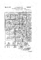
Fig. 4 shows'a link circuit for associating a sender with the district selector;
Fig. 5 shows a skeletonized disclosure of a register sender;
Fig. 7 shows in schematic form selectors for completing a connection to an automatic subscribers line, to a manual oflice or to an operators position; I
Fig. 8 shows a timing switchindividual to the line finder-district selector link of Figs. 3 and 6 for measuring the initial and overtime periods of conversation allotted to a calling subscriber for calls to different zones of the exchange area, and for seizing the common message register connector circuit;
Figs. 9 and 10 taken together show a common message register connector circuit for connecting the message register of a calling party line substation into an operating circuit and for controlling the manner in which the connected message register shall .be operated for calls to different zones; I
Fig. 11 shows the manner in which Figs. 1 to 10 should be .arranged to completely disclose the invention.
portion versation. As soon as this charging is com- The invention has been embodied in a displeted the timing switch is advanced to dismiss the common circuit and under the control of a timing interrupter to measure off a period of time prescribed for the initial period of conversation, which period may differ in accordance with the zone of the exchange area into which the connection has been extended. If the conversation continues at the end of this period, the timing switch is caused to start upon a second cycle, again seizing the common register connector circuit and causing the operation of .the calling closure which is similar to that of U. S. Patent 1,567,072, granted'to W. H. Matthies, December 29, 1925, both the present disclosure and that of'the Matthies patent showing a skeletonized sender substantially the same as that disclosed in the more complete disclosure of U. S. Patent 1,589,402, granted to O. H. Kopp, June 22, 1926, and reference to the Kopp patent is made for operations not completely described herein.
As disclosed in the above mentioned patentsa plurality of link circuits isarranged to serve a group of calling lines'and are taken into service in rotation. When a link circuit completes its function it hunts for and associates itself with a district selector which is ready for use and the link and district remain in a sub-allotted condition until the next l nk inthe series has been put into service. The link circuit is then put into an allotted position from whichit'will be advanced by the initiation of a call and the action of the start circuit of Fig. 2. The trip circuit of Fig. 1 and start circuit of Fig.2 areso arranged that only one line may be served at a time and so that there may be cooperatimi between two groups of lines to each of which a group of link circuits is individual. The details of these functions are described in the above mentioned Matthies patent and since they form no part of the present invention will be omitted from the following description.
Establishment of a connection from substa- V at substation J first initiates a call for line 700 in zone 5 of the exchange area for which he is to be charged five times for the' first three minutes of 'conversationand once for each one minute overtime period of conversation. When the subscriber at substation J removes his receiver from the switchhook a circuit is closed from battery through the winding of relay 101, back contact of relay 102, over the subscribers line to ground at the outer contact of relay 102. Relay 101 in operating closes a circuit from battery, winding of relay 103, right back contact of relay 104 to ground at the outer front contact of relay 101. It also prepares a circuit from battery through resistance 111 and the right winding of marginal relay 109 in parallel, inner front contact of relay 101 to conductor 114, to identify the calling line to the line finder. Relay 103 in operating closes a circuit from battery over the back contact of relay 201, conductor 130, right winding of relay 108, inner back contact of relay 107, back contacts of relay 109, middle left contact of relay 103 to ground. 7
Relay 108 operates in this circuit and closes a locking circuit for itself from battery through the right winding of relay 201, conductor 129, over back contacts of relays similar to relay 108 individual to other groups of lines appearing before the same line finder, inner left front contact and left winding of relay 108, the right back contact of relay 109 to ground at the middle left front contact of relay 103. Relay 108 prepares a circuit from groun at its outer right contact through the winding of trip magnet 303 of the line finder to battery in preparation for tripping the proper set of brushes when the line finder is operated. Relay 201 operates in the locking circuit of relay 108 and in combmation therewith closes a circuit from ground over its outer right contact, conductor 128, inner right contact of relay 108, winding of relay 110 to battery. Relay 110 locks over its inner right contact, the left back contact of relay 109 to ground at the middle left front contact of relay. 103. Relay 110 closes a starting circuit for the allotted line finder.
Assuming that the link and line finder shown are the ones to be used next, sequence swltch 400'willbe standing in position 1 and sequence switch 600 in position 2. The op eratlon of relay 110 will therefore close a. circult from ground at its outer right contact, outer left front contact ."of relay 108, inner left front contact of relay 103, conductor 131, left back contact of relay 202, inner left back contact of relay 203, conductor 206, upper left and lower right contacts of cam 403, brush 402 and terminal 401, conductor 378,
i upper left contact of cam 601, lower left conpact of cam 602, winding of relay 302 to batery.
Relay 302, upon operating, closes a circuit from battery through the winding of updrlve magnet 304 of the line finder, outer right contact of relay 302 and in parallel through the winding of relay 300, upper contacts of cam 603, inner left front contact of relay 302 to ground at the lower left contact of cam 604. Relay 302 also locks over its inner right front contact, the upper left and lower right contacts of cam 605, the back contact of relay 305 to ground over commutator segment 306 and brush 307. The line finder moves upwardly under the control ofmagnet 304 and since trip magnet 303 is operated, the proper set of brushes is tripped. The operation of relay 300 at its right back contact removes ground from the line finder brush 326 during hunting, and prepares a circuit which is closed as soon as commutator brush 308 engages segment 309 which extends from ground on brush 308, outer left contact of relay 300, conductor 404, contact 230 of key 204, inner right front contact of relay 201 to conductor 129 and the right. winding of relay 201. This circuit shunts the winding of relay 108 and causes that relay to release, in turn, releasing the trip magnet 303. W hen the brush 308 leaves segment 300 the circuit of relay 201 is opened and that relay also releases. When line finder brush 381 makes contact with terminal 380 which is connected over conductor 114 to battery, a circuit is completed over conductor 310, the upper left and lower right contacts of cam 803, conductor 311, winding of relay 305, conductor 312, lower right and upper left contacts of cam 804, conductor 805, outer left back contact of relay 301, conductor 31.3 to ground over the lowe left and upper right contacts of cam 606. "Relay 305 operates in this circuit and closes a shunt around its winding from ground over commutator brush 307 and segment 306, front contact of relay 305, conductor 313, resistance 806, lower contacts of cam 803, thence as traced through 5 the winding of relay 305 to ground at cam 606. This shunt circuit reduces the resistance in series with the winding of marginal relay 109 sufficiently to cause .that relay to operate and to open the locking circuit of relay 110 which, in turn, opens the energizing circuit of relay 302. The operation of relay 305 also opens one locking circuit of relay 302 causing that relay to release as soon as the line finder brushes become centered on the terminals of the calling line and commutator brush 314 engages an insulating portion of centering segment 315. The release of relay 302 opens the circuit of updrive magnet 304 to arrest the hunting movement of the line finder and opens the circuit of relay 300.
At the time relay 300 operated it closed a circuit from ground at its inner left contact over conductor 379, terminal 407 and brush 406 of finder 410, lower contact of cam 408, winding of relay 409, resistance 411 to battery. Relay 409 operates and-closes a circuit from battery through the winding of sequence switch magnet 400, upper contact of cam 412 to ground at the outer left front contact of relay 409, advancing the link sequence switch 400 to position 2. When the switch 400 leaves position 1, relay 409 releases. In position 2 a circuit is closed from battery, through the winding of relay 413, the upper contacts of cam 414, right back contact of relay 415 to ground at the lower right contact of cam 416. Relay 413 operates closing a circuit from battery through the left winding of relay 417, left front contact of relay 413 to ground at the left back contact of relay 415. Relay 417, in operating, closes a circuit from battery through the winding of updrive magnet 418 of the sender finder 420, left contact of cam 479, outer right front contact of relay 417 to ground at the left back contact of relay 409. The sender finder moves upwardly under the control of magnet 418 in search of an idle sender.
Relay 413 also closes a circuit from battery through the right winding of relay 415, the upper right and lower left contacts of cam 421, middle winding of relay 415 to ground at the right contact of relay 413. The current in this circuit, however, is not sufficient to operate relay 415 but does create a flux in its magnetic circuit so that it becomes quick to operate when the test circuit is later closed. The test circuit extends from brush 422, over the lower contacts of cam 419, the right back contact of relay 409, the left winding of relay 415, the lower contacts of cam 421, middle winding of relay 415 to ground at the right contact of relay 413.
An idle sender is characterized by battery connected to conductor 502. When, therefore, brush 422 engages terminal 423 corresponding to the sender of Fig. 5 which is assumed to be idle, the test circuit above traced is completed over terminal 423to battery and relay 415 operates quickly. Relay 415, in operating, closes a locking circuit for itself from battery, through its right winding, upper right and lower left contacts of cam 421 to ground at the left front contact of relay 415. It also opens the circuit of re-' lay 417 which releases to, in turn, release magnet 418 and bring the sender finder to rest on the terminals of the idle sender. The release of relay 417, in turn, releases relay 413. With relay 413 released and relay 415 operated, a circuit is closed from battery through the winding of sequence switch magnet 400, lower left contact of cam 476, contact 427 of jack 428, left back contact of relay 413, right front contact of relay 415 to ground at the lower right contact of cam 416, advancing sequence switch 400 to position 3. When the link circuit advanced into position 2 for hunting for an idle sender, a circuit was closed for relay 318 extending from battery, right winding of relay 318', lower right contact of cam 610, upper right contact of cam 611, conductor 375, terminal 477 and brush 478 of district finder 410 to ground at the upper right contact of cam 429. Relay 318 locks over its inner right front contact and the upper contacts of cam 606 to ground. A circuit is now established for advancing sequence switch 600 into position 3 which may be traced from battery through magnet 600, the lower right contact of cam 612, the left front contact of relay 318, conductor 319, lower contacts of cam 807, conductor 808, the left back contact of relay 302 to ground at the lower left contact of cam 604. 5 As the sequence switch 600 advances from position 2 to 3, relay 318 releases. l Vith sequence switch 600 in position 3, busy ground is applied to the sleeve conductor 112 of the calling line over line finder brush 326, right back contact of relay 300, resistance 317, inner lower back contact of relay 316 conductor 812 to ground at the upper left contact of cam 607. Cut-off relay 102 of the calling line operates over this circuit releas- 115 ing line relay 101 which,-in turn, removes battery from conductor 114, thereby releasing relay 305. With sequence switch 600 in position 3 a circuit is established from battery through the winding of relay 322, resistance 323, lower right contact of cam 601, upper right contact of cam. 602, segment 335 and brush 336 to ground for testing the sensitivity of test relay 322. Relay 322 should operate at this time and upon operating establishes a circuit for relay 324 extending from battery through the winding of relay 324, outer left back contact of relay 325 to groundat the contact of relay 322. Relay 324 upon operating looks over. its inner right relays 316 and 329, brush 334, terminal 333,
front contact to ground at the lower left contactof cam 617. If relay 322 does not operate the call is blocked and an alarm signal is given.
\Vhen sequence switch 400 reaches positlon 3 a circuit is closed from ground through the left and middle windings of relay 503, back contacts of relays 504 and 505, conductor 506, terminal 430. brush 431. right contact of cam 434, brush 432, terminal 433, conductor 314, lower leftand upper right contacts of cam 613, assuming that the district selector sequence switch 600 has new advanced to posltion 3, through the winding of relay 351 to battery and in parallel over the lower contacts of cam 613 to battery through the lower winding of relay 316. Relay 316 is marginal and does not operate but relay 315 operates although ineffective at this time. Relay 503 operates and closes an obvious circuit for relay 507 which, in turn, closes a circuit for relay 509. Relay 509 operates relay 510.
As soon as sequence switch 400 arrived in position 2 it prepared a pulsing circuit for receiving dial pulses. This circuit may be traced from battery through the left winding. of relay 500, conductor 537, terminal 440, brush 441,- lower contacts of cam 429, brush 47 8, terminal 477, conductor 375, left contact of cam 615, upper back contacts of conductor 116, through the subscribers substation conductor 117, terminal 332,. brush 331, outer lower back contacts of relays 329 and 316, winding of relay 320, left contacts of cam 617, conductor 382, terminal 442, brush 443, upper right and lower left contacts of cam 403, brush 444, terminal 445 to ground at the back contact of relay 513. Relay 500 operates in turn operating relay 518 in the well-known manner, relay 518, in turn, operating relay 519. A circuit is thereupon closed from the source of tone 516 through the right winding of relay 500, switch 520 in normal position, front contact of relay 519, contact of cam 514 to ground at the front contact of relay 509. This tone is transmitted to the calling subscriber to inform him that the sender is ready to receive impulses which he may then send by manipulating his dial.
\Vhen relay 510 operated it removed battery from conductor 502releasing relay 415. \Vith relay 415 released, a circuit is closed from battery, through the winding of sequence switch magnet 400, upper left contact of cam 476, right back contact of relay 415 to ground at the lower right contact of cam 416 for advancing sequence switch 400 into position 5. Sequence switch 400 remains in position 5 throughout the further operation of the sender. The calling subscriber now proceeds to dial the desired line number for setting the registers and translator of the sender in the well-known mannerr After dialing the first digit the switch, the wlper of which is shown at 520, advances from normal closing a circuit extending from battery through the winding of relay 517, terminals and wiper 520, contacts of relay 519, contact of cum 514 to ground at the outer right contacts of earn 509. Relay 517 closes an obvious circuit for relay 521.
As soon as the code registers of the sender have been set in accordance with the first two digits dialed by the calling subscriber, the translator is set in a manner described in the aforementioned patent to O. H. Kopp. When the translator assumes its setting, 're-' lay 533 operates and circuits are prepared over the translator are 534, through a back contact of relay 535 for operating either relay 536 or relay 547 .or neither of them dependent upon in which zone of'the exchange the wanted line is located. For example, vif a called number isvdialed for either zone 0 or zone 1, neither relay 536nor 547 will be operated. If a call is dialed for either zone 2 or zone 3, relay 536 will be operated and if the call is for either zone 4 or zone 5, relay 547 will be operated. It will be assumed that a call is for a subscribers line terminating in the fifth zone and that therefore relay 547 is operated over a circuit extending from battery, winding of relay 547, back contact of relay 535, translator are 534 to ground at the contact of relay 533. Relay 547 locks over its left front contact, the contact of cam 514 to ground at the outer right front contact of relay 509 and extends its locking ground to the winding of relay 538. Relay 538 upon operating establishes a circuit from ground at the outer right contact of relay 509 over the contact of cam 514, the contact of relay 538 to battery through the winding of relay 535. Relay 535 operates opening the initial energizing circuit of relay 547 and connecting the translator are 534 over a cable 539 to the class switch 540, which is diagrammatically indicated in the upper right portion of Fig. 5. The class switch is thereupon set from the are 534 of the translator. With relay 547 operated and relay 536 non-operated, a circuit is prepared extending from battery through low resistance 549, right front contact of relay 547, right back contact of relay 536, the contacts of cams 541 and 542, these cams being closed during the district brush selection positions of the sequence switches associated with the sender, conductor 543, terminal 439, brush 438, right contacts of cam 405, brush 406, terminal 407, conductor 379 to the upper right contact of cam 609.
This circuit is completed as will be hereinafter described when the district sequence switch is advanced to position 4, through the lower windings of zone relays 809 and 810 of the timing circuit of Fig. 8 for indicating the fact that the subscriber has made a call to a particular zone of the exchange, in the case assumed, the fifth zone. It may be noted at this time that due to the inclusion of the lowresistance 549, both zone relays 809 and 810 will operate. Had relay 536 been operated, then battery through highresistance 548 would have been connected over the circuit just traced and only relay 810 would then be operated as soon as the district sequence switch reaches position 4. -If neither relay 536 nor 547 operate, then direct ground is connected to the circuit prepared through the windings of relays 809 and 810 and neither of the latter relays will operate.
With sequence switch 600 in position 3 relay 318 is energized over a circuit extending from battery through its right winding, the lower right contact of cam 610, the lower left contact of cam 611, conductor 378, terminal 401 and brush 402 of district finder 410, the left contacts of cam 435, brush 436 and terminal 437 of sender finder 420, conductor 542, the contact of relay 521, the back contact of relay 504, right contact of cam 526, Winding of sender stepping relay 522, back contact of counting relay 525, left winding of overflow relay 523, left contact of cam 527, resistance 530 to ground. Relays 522 and 318 operate, relay 318 looking over its inner right front contact, the upper left contact of cam 610, thence over the circuit traced, whereby it remains energized as the sequence switch 600 advances into position 4. Relay 318 also closes a circuit to advance sequence switch 600 into position 4, extending from battery through the winding of magnet 600, lower right contact of cam 608, the outer right front contact of relay 324, the left front contact of relay 318, conductor 319, the lower contacts of cam 807, conductor 808, left back contact of relay 302 to ground at the lower left contact of cam 604. As sequence switch 600 advances out of position 3, relays 322 and 324 release.
When the district sequence switch 600 reaches position 4 for controlling brush selection, the circuit previously traced from the contact of relay 547 and extending to the upper right contact of cam 609 is extended over the upper left contact of this cam, conductor 811 to ground through the lower windings of zone relays 809 and 810. These relays operate and look over their upper windings and inner upper front contacts, conductor 812 to ground at the upper left contact of cam 607.
The district selector is now controlled by the sender in its brush and group selection movements and then proceeds to hunt for an idle trunk in the Well-known manner. After an idle trunk is selected a circuit is established in position 9 of sequence switch 600 for relay 318, extending from battery through its left winding, the lower contact of cam 618, the lower left contact of cam 601,
the iimer left back contact of relay 324 to ground at the left front contact of relay 351. clay 318, upon operating, advances sequence switch 600 into position 10 over a circuit extending from battery, winding of magnet 600, lower right contact of cam 612, left front contact of relay 318, conductor 319, lower contacts of cam 807, conductor 808, left back contact of relay 302 to ground at the lower left contact of cam 60 In position 10, relay 318 remains energized over the circuit previously traced. In position 10 which is the selection beyond position of the district selector sequence switch, the control of succeeding switches is effected over a fundamental circuit which may be traced in part vfrom brush 621, the upper right and-lower left contacts of cam 622, the right back contact of relay 321,
right contacts of cam 624 to brush 625.
As soon as the selections are completed and the connection has been set up to the called subscribers line, reversed battery from the incoming selector 701 operates relays 522 and 523 in the usual manner and these relays, in turn, cause the operation of the relays 531, 524 and 504. lVith these relays operated, the sender sequence switch is advanced to position 18 for controlling talking selection. Relay 315 is operated in parallel with the lower winding of relay 316 throughout selections. The operation of relay 504, above mentioned, now opens a shunt around the right winding of relay 503 including that winding in the circuit of relays 351 and 316. Relay 35 1 thereupon releases, in turn, opening the circuit of relay 318 which also releases. Upon the release of relay 318 the district sequence switch 600 is advanced into position 11 over a circuit extending from battery, winding of magnet 600, upper left contact of cam 608, left back contact of relay 318, thence as traced to ground at the lower left contact of cam 604. As the sequence switch enters position 11 ground is connected to conductor 314 at the lower right contact of cam 617, over terminal 433, brush 432, upper contacts of cam 446, left winding of relay 415, right back contact of relay 409, lower contact of cam 434, brush 431, terminal 430, conductor 506, left back contact of relay 505, windings of relay 503. Since these windings are also connected to ground, relay 503 now releases, in turn, releasing relay 507. The release of relay 507 does not release relay 509 since that-relay is locked to its own front contact. A circuit ft contact to conround as above traced.
locks over its middle ductor 506 and to After leaving position 10, relay 316 is disconnected from conductor 314.
With sequence switch 600 in position 11 the subscribers line becomes disconnected fromthe sender at contacts of cams 615 and 617 and relay 329 is operated in a circuit extending from battery, through its upper winding, the upper back contact of relay 330, the lower right and upper left contact of earn 619 to ground at the upper right contact of cam 617. Relay 329 upon operating extends its operating circuitover its middle upper front contact to battery through the winding of relay 338 which operates. At its inner right and left front contacts relay 338 connects the winding of relay 322 to the tip-and ring conductors 116 and 117 of the calling line, and establishes a holding circuit from ground at its middle left contact through the lower winding of relay 329 to insure that rea lay 329 will remain operated until after relay (iii 338 has released to disconnect relay 322 from conductors 116 and 117. At the time relay 329 operated the operating ground therefore is also connected to the cam Contact of interrupter 339 and thence as soon as interrupter 339 closes its lower contact to battery, through the right winding of relay 340. Relay 340 operates and locks over its inner right front contact to the operating ground independently of interrupter 339 and as soon as interrupter 339 makes its upper contact, establishes a circuit for relay 302 extending from battery through the winding of relay 302, middle right front contact of relay 338, outer rightfront contact of relay 340, upper contact of interrupter 339, thence to ground as traced at the upper right contact of cam 617. Relay 302 upon operating locks over its inner right front contact to ground at the lower front contact of relay 329 and at its inner left front contact establishes a circuit for advancing sequence switch 600 into position 12. This circuit extends from battery through the winding of magnet 600, the upper left contact of cam 612, conductor 620, the upper right and lower left contacts of cam 801, conductor 802, the inner left front contact of relay 302 to ground at the lower left contact of earn 604. Upon leaving position 11% the operating circuits of relays 329 and 338 and the holding circuit of relay 340 are "opened and relays 338 and 340 release. Re-
lay 338, upon releasing, opening the holding circuit of relay 329 which in turn releases, opening the holding circuit of relay 302. It has been assumed that the substation J has initiated the call and that therefore when relay 322 was connected to the calling line conductors upon the operation of relay 338 it did not operate as the operating ground at substation J extends through the substation bell and a condenser. Since relay 322 did not operate 'no circuit was established thereby for operating the message register switching relay 324 and therefore the fact that relay 324 is not operated registers in the district circuit'that the party J has initiated the call. Had the party W initiated the call then when the test relay 322 is connected to the line conductors the circuit of relay 322 is completed-through the substation bell of the substation W to ground, and relay 322,
upon operating, operates relay 324 which then looks over its inner right front contact to ground at the lower left contact of cam 617, registering the fact that the party W has initiated the call.
Talking selection With sequence switch 600 in position 12 the calling substation is connected in a talking path extending from ground throughthe upper left winding of repeating coil 631, lower right contact of cam 615, upper back contacts of relays 316 and 329, brush 334, terminal 333, line conductor 116, through the calling substation J, line conductor 117, terminal 332, brush 331, lower back contacts of relays 329 and 316, winding of supervisory relay 320, upper contacts of cam 617 to battery through the lower left winding of coil 631. Relay 320 operates in this circuit and remains operated until the calling subscriber hangs up and establishes a circuit for relay 301 extending over the contact of relay 320, the upper right and lower left contacts of cam 605 to ground at commutator brush 336.
A circuit is also established for relay 318 extending from battery through its right winding, the lower right contact of cam 610, lower left contact of cam 611, conductor 378, terminal 401, brush 402, left contacts of cam 435, brush 436, terminal 437, conductor 542, front contact of relay 521, front contact of relay 504, right contact of cam 526, the sender sequence switch being in position 18 for talking selection, windings of relays 522 and 523, right contact of cam 527, right back contact of relay 507 to ground through resistance 530. Relays 318 and 522 energize relay 318 closing a circuit extending from battery through sequence switch magnet 600, the lower right contact of cam 612, the left front contact of relay 318, thence to ground at the lower left contact of cam 604, as previously traced. Relay 318, upon energizing, locks over its inner right front contact, the upper left contact of cam 610, thence over the fundamental circuit as traced. As sequence switch 600 rotates out of position 12 toward position 16, ground is intermittently connected to the fundamental circuit in shunt of sender stepping relay 522 over the upper contacts of cam 606. When the sender is satisfied as to its talking selection setting, the fundamental circuit is opened at the sender through the operation of relay 525. Relay 318 deenergizes arresting sequence switch 600 in its next stopping position, The sequence switch may be arrested in any one of three positions, position 13, which is a charging po sition for connections to zones 0, 2 and 4, po-
- sition 14 which is a charging position for connections to zones 1, 3 and 5 and position 15 for connections to an operators position. Since it has been assumed that the calling subscriber has made a call to zone 5 of the exchange, the district selector sequence switch will be arrested in talking selection position 14.
. At the sender after. talking selection is completed relay 515 operates connecting battery to conductor 506 in parallel with the winding of relay 505. The current in this circuit is now suificient to operate relaiy 415 which closes a circuit from battery through the left winding of relay 417, left contacts of cam 421 to ground at the left front contact of relay 415. Relay 417 closes a circuit from battery through the winding of sequence switch magnet 400, upper contact of cam 479, outer right front cont-act of relay 417, left back contact of relay 409 to ground, advancing sequence switch 400 to position 6. In this position all the conductors extending to the sender are opened and the sender is completely released. As soon as sequence switch 400 leaves position 5 relay 415 releases and, in turn, releases relay 417 unless the sender finder 420 is standing on one of its top ten terminals. If the latter condition exists relay 417 is held operated in a circuit from battery over its left winding and left front contact, upper left contact of cam 424, commutator segment 464, brush 463 to ground. With relay 417 operated at this time a circuit is closed from battery through resistance 411, winding of relay 409, lower contact-s of cam 414, inner right front contact of relay 417, lower right contact of cam 416 to ground. Relay 409 looks through its inner left contacts to ground at the lower confacts of cam 467 and also closes a second locking circuit for relay 417. lVith relay 409 operated a circuit is closed from battery through the winding of downdrive magnet 465 of the sender finder 420, left contact of cam 412 to ground at the outer left front contact of relay 409. When the sender finder reaches its lowermost position a circuit is closed from ground, over brush 463, bottom commutator segment 406, lower right contact of cam 456 to resistance 411. shunting the winding of relay 409 and causing that relay to release, in turn, releasing relay 417. With relay 417 released, in position 6 a circuit is closed from battery through the winding of sequence switch magnet 400, lower right contact of cam 476, right back contact of relay 417 to ground at the lower right contact of cam 416, advancing sequence switch 400 to position 7.
When sequence switch 400 reaches position 7, thelink circuit is ready to associate itself with another district selector which is standing in position 1 awaiting association. with a link and a circuit will be closed from ground over the upper right contact of cam 617, the
upper left contact of cam 619, the lower right contact of cam 623, contacts 341 of jack 340, conductor 392, contact of jack 448, contact of jack 449, upper right contacts of cam 416, right back contact of relay 415, upper contacts of cam 414, winding of relay 413 to bat- U tery. Relay 413 closes a circuit from battery through the left winding of relay 417, left front contact of relay 413'to ground at the left back contact of relay 415. Relay 417 in operating closes a circuit for updrive magnet 447 of the district finder 410, lower right contact of cam 479, outer, right front contact of cuit extends from conductor 366, terminal 450, brush 451, contact of ack 449, upper left and lower right contacts of -cam 419, right back contact of relay 409, left winding of relay 415, lower contacts of cam 421, middle winding of relay 415, to ground at the right contact of relay 413.
If the district selector for which the finder 410 is hunting does not lie between the last. position occupied by the finder and the top of the bank, it will continue to move upwardly until brush 453 engages segment 452, completing a circuit over the upper right contact of cam 408, Winding of relay 409, resistance 411 to battery. Relay 409 opens the test circuit, opens the circuit of updrive magnet 447 and closes a circuit from battery through the winding of downdrive magnet 454, lower contact of cam 412, left front contact of relay 409 to ground. The finder 410 is restored to its lowermost position under the control of magnet 454 at which time a. circuit is closed from ground over brush 453, bottom segment 455 of the finder commutator, upper right contact of cam 456, resistance 411 to battery, shunting and releasing relay 409 which restores the test circuit and the circuit of updrive magnet 447. When brush 451 enco unters terminal 450 to which conductor 366 extends the test circuit is completed and relay 415 operates, locking through its right winding, the upper right and lower left contacts of cam 421 to ground at its outer left" front contact, opening the circuit of relay 417 to deenergize magnet 447 and to bring the finder 410 to reston the terminals of the district selector. With relay 415 operated and relay 417 released a c1rcuit is closed from battery through the winding of sequence switch magnet 400, lower left contact of cam 476, contact 427 of ack 428, the left back contact of relay 413, right front contact of relay 415, upper contact of ram 416, contacts of jacks 449 and 448 to ground on conductor 392, advancing sequence switch 400 to position 8.
contact of cam 262, conductor 263, contact 460 of jack 428, right contacts of cams 461 and 462 to battery through the winding of sequence switch magnet 400, advancing the sequence switch to position 10 which is the equivalent of position 1 so that the link circuit is ready to operate in response to the next call in the group of lines served thereby.
Making initial charge for a call in zone 5 of the exchange area It will be recalled that for a call into 'zone 5 of the exchange area the district sequence switch 600 was arrested in talking position 14 and that both zone relays 809 and 810 have been operated and locked. When the called subscriber 700 responds after the application of ringing current to his line from the incoming selector 701, in the well known manner, relay 627 operates in a circuit which may be traced in part from brush 621, the upper contacts of cam 622, the upper right winding of repeating coil 631, winding of relay 627, lower right winding of coil 631, upper contacts of cam 624, to brush 625. erating, relay 627 establishes a circuit from ground at the right contacts of cam 607, front contact of relay 627, upper contacts of cam 623, conductor 628, right contacts of cam 813, conductor 814, lower contact of inter raptor 3-13, conductor 815, upper left and lower right contacts of cam 816, conductor 81.7, left winding of relay 340 to battery. Relay 340 operates and looks over the circuit previously traced to conductor 814, thence over the outer left front contact ofrelay 340, conductor 815, thence as traced to battery through the loft winding of relay 340. As soon as interrupter 343 makes its upper contact, a circuit is established from battery through the winding of sequence switch magnet 800, lower right contact of cam 818, right contacts of earn 819, conductor 822, upper contacts of cam 618, conductor 630, inner left front contact of relay 340, upper contact of interrupter 343, conductor 814, thence to ground as traced over the front contact of relay 627, to ground at the right contacts of cam 607 for advancing sequence switch 800 into position 2. Upon leaving position 1 the holding circuit of relay 340 is opened and relay 340releases.
As soon as sequence switch 800 leaves normal, a circuit is established for relay 325, extending from battery through the winding of relay 325, conductor 345, upper right and lower left contacts of cam 816, conductor 831, to ground at the lower left contact of cam 617. Relay 325 upon operating extends its operating ground to the winding of relay 321 over its inner right front contact, thereby operating relay .321 which looks itself and relay 325 over itainner left front contact to ground at the lower contacts of cam 607.
With sequence switch 800 in position 2, a start circuit is established from ground on conductor 628, over the lower left contact of cam 813, upper winding of relay 823, conductor 824, left back contact of relay 1000, right back contact of relay 1001, right back contact of relay 1002, winding of relay 1003, to battery at the back contact of relay 1004, if the message register connector circuit of Figs. 10 and 11 is at the time free. Relays 1003 and 823 operate and if the timing circuit of Fig. 8 occupies apreferential position with respect to other timing circuits, relay 823 locks over its lower winding, the left contacts of cam 825, the upper front contact of relay 823, conductor 826, right back contact of relay 1000, winding of relay 1004, to ground at the left back contact of relay 1002. Relay 1004 operates in this locking Upon opwinding of relay 1006.
obvious circuit for relay 1001 thereby connecting the start conductor 824 over the left back contact of relay 1000, the right front contact of relay 1001 to ound through the operate at this time. Relay 827 .also operates in parallel with the locking winding of relay 823, extending common operating leads 850 from the connector circuit tothe district;
selector circuit and at its middle upper front contact establishes a circuit from ground I over conductor 828, to battery through the winding of relay 344, thereby operating this relay. A circuit is now established either for .relay 900 or relay 901 depending upon whether the party test relay 324 was or was not operated. In the case assumed, relay 324 i was not operated and therefor with relay 344 operated, relay 900 is operated over a circuit extending from battery, winding of relay 902, winding of relay 900, conductor 903, inner upper from contact of relay, 344, left back contact of relay 324, lower frpnt contact of relay 344, lower contacts of cam 605, commutator segment 335, brush 336 to ground. Had relay 324 operated through the initiation of a call by the party W, then relay 901 is operated from battery, winding of relay 902, winding of relay 901, conductor 904, upper front contact of relay 344, left front contact of relay 324, thence to ground as traced at brush 336. Relay 902 being marginal does not operate in the circuit of either relay 900 or relay 901.
With relay- 900 operated circuits are closed for five multi-contact relays, one of which is shown at 905, and each relay 905 extends its operating circuit to a corresponding multi-contact relay 906. Each multi-contact relay, such as 905 and 906, controls operating circuits extending to forty message registers, and thus as soon as five relays similar to relay 905 and five relays similar to relay 906 are operated through the operation of relay 900, the message registers of all substations corresponding to the substation J of the 400 lines-appearing in the line finder in Fig. 3 are connected through the contacts of these relays to the corresponding operating conductors of'the 400 lines terminating in terminals corresponding to terminal 380 appearing in the line finder bank. For example the circuit of message register 105 of the calling party J may be traced in part from terminal 380, conductor 114, the back contact of line relay 101, conductor 106, the outer right front contact of relay 905, conductor 907 to ground through message register 105. Had relay 901 operated, in turn operating five multi-contact relays corresponding to relay 908 and in turn five multi-contact relays corelay 1006 does not respondin to relay 909, then the message registers of a l substations corresponding to the substation W of the same 400 lines would be connected to the operating conductors of the 400 lines terminating in terminals corresponding to terminal 380. For example, in that case the circuit through message reg ister magnet 135 may be traced in part from terminal 380, conductor 114, back'contact of line relay 101, conductor 106, theouter right front contact of relay 908, conductor 910 to ground through 'message register 135.
With either relay 900 or 901 operated, a
circuit is established from ground in parallel through back contacts of multi-contact relays controlled thereby to' battery through the winding of relay 911. Relay 911 operates and remains operated until all of the multicontact relays, such as 905, 906 which should operatehave operated, and at its left back contact opens the operating circuit 'of charging relay 1007 to prevent initiation of charging. In the event that both relays 900 and 901 operate erroneously, the marginal relay 902 will receive current to operate and will in turn hold relay 911 operated to prevent charging.
Referring to the operation of the timing circuit of Fig. 8, it will be recalled that I sequence switch 800 is standing in position 2 and that relays 823 and 827 are operated. It will also be recalled that for calls to zones 0, 2 or 4, sequence switch 600 will be standing in position 13 and that for calls to zones 1, 3 or 5 it will be standing in position 14. A test is now'made of the continuity of common conductors 850 extending through front contacts of relay 827 to the windings of zone relays in the connector circuit. One of these test circuits extends from battery through the winding of relay 913, winding of zone relay 914, conductor 835, upper front contact of relay 827, left contacts of cam 834, to ground at the inner lower front contact of relay 810 if relay 810 is operated, or over the inner lower back Contact of this relay, the left contacts of cam 839 to ground at the lower front contact of relay 823, if relay 810 is not operated. Another circuit extends from battery through the winding of relay 913, the winding of relay 915, conductor 1010, the right back contact of relay 1008, conductor 836, the lower front contact of relay 827, the lower right and upper left contacts of cam' 829 to ground at the upper front contact of relay 809 if it is operated, or if it is not operated over its upper back contact through the left contacts of cam 839 to ground at the lower front contact of relay 823. If sequence switch 600 is in position 13, a circuit is established from battery, winding of relay 913, winding of zone relay 912, con ductor 840, inner lower front contact of relay 827, left contacts of cam 842, upper front contact of relay 810, which is operated
Priority Applications (1)
| Application Number | Priority Date | Filing Date | Title |
|---|---|---|---|
| US464442A US1859924A (en) | 1930-06-28 | 1930-06-28 | Call charging telephone exchange system |
Applications Claiming Priority (1)
| Application Number | Priority Date | Filing Date | Title |
|---|---|---|---|
| US464442A US1859924A (en) | 1930-06-28 | 1930-06-28 | Call charging telephone exchange system |
Publications (1)
| Publication Number | Publication Date |
|---|---|
| US1859924A true US1859924A (en) | 1932-05-24 |
Family
ID=23843967
Family Applications (1)
| Application Number | Title | Priority Date | Filing Date |
|---|---|---|---|
| US464442A Expired - Lifetime US1859924A (en) | 1930-06-28 | 1930-06-28 | Call charging telephone exchange system |
Country Status (1)
| Country | Link |
|---|---|
| US (1) | US1859924A (en) |
Cited By (6)
| Publication number | Priority date | Publication date | Assignee | Title |
|---|---|---|---|---|
| US2426981A (en) * | 1942-06-27 | 1947-09-09 | Bell Telephone Labor Inc | Automatic toll ticketing alarm system |
| US2434697A (en) * | 1943-09-28 | 1948-01-20 | Charles H Homrighous | Time division multiplex telephone system |
| US2447533A (en) * | 1942-06-27 | 1948-08-24 | Bell Telephone Labor Inc | Automatic toll ticketing system |
| US2486722A (en) * | 1938-06-21 | 1949-11-01 | Automatic Elect Lab | Automatic toll-ticketing telephone system |
| US2566330A (en) * | 1945-06-23 | 1951-09-04 | Standard Telephones Cables Ltd | Metering arrangement for telephone systems |
| US2629016A (en) * | 1942-06-27 | 1953-02-17 | Bell Telephone Labor Inc | Automatic toll-ticketing system |
-
1930
- 1930-06-28 US US464442A patent/US1859924A/en not_active Expired - Lifetime
Cited By (6)
| Publication number | Priority date | Publication date | Assignee | Title |
|---|---|---|---|---|
| US2486722A (en) * | 1938-06-21 | 1949-11-01 | Automatic Elect Lab | Automatic toll-ticketing telephone system |
| US2426981A (en) * | 1942-06-27 | 1947-09-09 | Bell Telephone Labor Inc | Automatic toll ticketing alarm system |
| US2447533A (en) * | 1942-06-27 | 1948-08-24 | Bell Telephone Labor Inc | Automatic toll ticketing system |
| US2629016A (en) * | 1942-06-27 | 1953-02-17 | Bell Telephone Labor Inc | Automatic toll-ticketing system |
| US2434697A (en) * | 1943-09-28 | 1948-01-20 | Charles H Homrighous | Time division multiplex telephone system |
| US2566330A (en) * | 1945-06-23 | 1951-09-04 | Standard Telephones Cables Ltd | Metering arrangement for telephone systems |
Similar Documents
| Publication | Publication Date | Title |
|---|---|---|
| US1859924A (en) | Call charging telephone exchange system | |
| US2258651A (en) | Telephone system | |
| US1663747A (en) | Telephone-exchange system | |
| US2262595A (en) | Telephone system | |
| US1910972A (en) | Telephone system | |
| US2516814A (en) | Adapter circuit for establishing connections between automatic and magneto type subscribers | |
| US1944269A (en) | Telephone system | |
| US2427000A (en) | Coin-operated telephone system | |
| US2096436A (en) | Telephone system | |
| US1674677A (en) | Connecter-switch circuit | |
| US1916760A (en) | Telephone exchange system | |
| US1651017A (en) | Party-line revertible ringing system | |
| US1690206A (en) | Telephone system | |
| US2214809A (en) | Telephone system | |
| US1696275A (en) | Lewis h | |
| US1825723A (en) | Telephone system | |
| US1837206A (en) | Call charging telephone exchange system | |
| US2762865A (en) | Trunk circuit | |
| US2042561A (en) | Telephone system | |
| US1655061A (en) | Telephone-exchange system | |
| US1823040A (en) | Call charging telephone exchange system | |
| US2698881A (en) | Telephone system | |
| US1832447A (en) | Telephone system | |
| US3175044A (en) | Private branch exchange system with camp on facilities | |
| US1944244A (en) | Telephone system |