US1857701A - Flying target - Google Patents
Flying target Download PDFInfo
- Publication number
- US1857701A US1857701A US570426A US57042631A US1857701A US 1857701 A US1857701 A US 1857701A US 570426 A US570426 A US 570426A US 57042631 A US57042631 A US 57042631A US 1857701 A US1857701 A US 1857701A
- Authority
- US
- United States
- Prior art keywords
- hollow
- target
- members
- atmospheric pressure
- flying target
- Prior art date
- Legal status (The legal status is an assumption and is not a legal conclusion. Google has not performed a legal analysis and makes no representation as to the accuracy of the status listed.)
- Expired - Lifetime
Links
Images
Classifications
-
- F—MECHANICAL ENGINEERING; LIGHTING; HEATING; WEAPONS; BLASTING
- F41—WEAPONS
- F41J—TARGETS; TARGET RANGES; BULLET CATCHERS
- F41J9/00—Moving targets, i.e. moving when fired at
- F41J9/16—Clay-pigeon targets; Clay-disc targets
Definitions
- This invention relates to so-called flying targets for use in trap shooting, and has for one" of its objects to provide a target of this character which will fall when a hit isf'scored, but will not be destroyed, andwhich can be reconditioned and used again.
- Another object is to provide a target of this character which will more or less imitate the movements of a live birdwhen thrown from a trap in target shooting. Other objects will appear as the description of the invention proceeds.
- the invention consists of a hollow bodycomposed of two separable parts, which parts are held together by reducing the internal airpressure of the body, to the end that the external atmospheric pressure will hold the parts together, and when the vacuum or partial vacuumfis broken by 'admit-ting air tothe interior of the hollow body,
- the two parts may be hinged together at a single point, to the end that when one of the parts drops downward, it produces a tumblingeffect simulating that of a bird that had been brought down.
- the hollow body is preferably composed of metal, such as aluminum, tin, sheet iron or steel, pressed into form and, prefer-' 301 ably said body, which, for example, may be in the form of abody' of apige'omis separated into twoparts or members along the line of a horizontal plane.
- the metal of the body is of sufficient strength to resist, and not be perfora-ted, by the shot'ordinarily used in trap shooting, and the body itself is provided with a plurality of perforations, and the exterior of the body covered with some readily frangible material, such as a thin coating of clay or said planesor wings areattache'd to thef'bodyi adobe, which acts to seal the perforations airappended-claims for thislpurpose.
- the target can be recondis tioned by simply recoating said body with:
- the two members into which the body is divided along a horizontal plane may be hing ed together at a single point,fsay at the rear end of the body, when the same assumestheform of a pigeon, and when the vacuum is broken, the lower member dropsoiferingresistance to the air andcausing-atumbling effect: like that 'of a wounded bird.
- the target maybe caused, whenthrown or shot from a tr'ap,to takean.
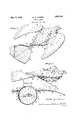
- Fig. 1 is a perspective View of the invention here shown in the form of a pigeon
- Fig. 2 is a side'view of the same
- Fig. 8 is a transverse section on the line 3-3 of Fig.2 looking in the direction of the 'preferablysomewhat below the median longi tudinal plane, and the lower member 2 is upper member 1 provided with an exteriorly-extendingflange 4 to serve as a guide and support for the target when it is'placed in and expelled from a trap.
- This flange portion has a gasket 5 extending entirely around the same, which gasket is composedof any suitable material, such as rubber, and the lower edge of the seats snugly on the gasket 5.
- the body portion has provided in it a plurality of holes or perforationsS, and the exterior of the entire body isxthencovered with a very thin coating of some frangible material, such as clay or adobe, which can be appliedwhen in a moist condition, but which, when dried, is readily shattered.
- some frangible material such as clay or adobe
- lVhen supporting planes hereshown in the form of wings B, B, are employed, said planes are, throughout a large portion of their extent, provided with hollow air chamber 9, Fig. 3, and at the point where said planes or wings join the body, the joint is formed by a hollow shaft portion 10, Fig. 3, entering the sockets 11 projecting from opposite sides of the body.
- the planes or wings B, B may be adjusted in any desired angles by simply turning the shaft portions 10 in the sockets'll and fixing the same in such'adand the hit is made on any part of the body,
- the target will falhand, furthermore, that the same may be readily reconditioned by simply recoating If the target assumes the form here illustrated, it will be. readily seen that whenever a hit is made on any part of the target, whether the body or wing portions, the effect will be almost exactly similar .to that which occurs when a live bird is hit.
- the body portion may be used without wing portions, and the body portion may readily shatterable material to close the perforation made by the shot; or the body may be provided with perforations and the body itself be made of material which would not be readily penetrated by the shot and the vacuum be broken by shattering the frangible coating.
- the body portion may be used without wing portions, and the body portion may readily shatterable material to close the perforation made by the shot; or the body may be provided with perforations and the body itself be made of material which would not be readily penetrated by the shot and the vacuum be broken by shattering the frangible coating.
- a flying target comprising .a hollow body composed of a plurality of members snugly fitted together, the interior pressure of said body being less than atmospheric pressure whereby the members are held closed together by atmospheric pressure.
- a flying target comprising a hollow perforated body exteriorly covered with a coating of frangible material, said body being composed of a plurality of members snugly fitted together, and the interior pressure of said body being less than atmospheric pressure.
- a flying target comprising a hollow body composed of a plurality of members snugly fitted together, andwinglike members jointed'to said body, the interior pressure of said body being less than atmospheric pressure.
- a flying target comprising a plurality of members snugly fitted together to formra hollow body, and hollow winglike members in open communication with the interior of said body, the interior pressure of said body being less than atmospheric pressure.
- a flying target comprising a hollow body with perforated walls exteriorly covered with a coating of frangible material, and winglike members jointed to said body, the interior pressure of said body being less than atmospheric pressure.
- a flying target comprising a pluralityof members snugly fitted together to form a hollow body, the interior pressure of said body being less than atmospheric pressure, and outwardly-extending oppositely disposed flanges on said body, whereby the target may be supported and guided in a propelling device.
- a flying target the combination of a hollow body composed of a plurality of members, the interior pressure of said body being less than atmospheric pressure whereby the said members are held in assembled position by atmospheric pressure, and a hollow wing or plane in open communication with the interior of said hollow body.
- a flyingtarget as. defined in claim 8 characterized by the fact that the body and wings are provided with perforations cov-' ered with a frangible material closing said perforations.
- a flyingtarget as defined in claim 12 characterized by the fact that said body is provided with a plurality of perforations covered with a frangible material closinglsaid perforations.
- a flying target the combination of a hollow body composed of a plurality of members one of which is hinged to another member, the interior pressure of said body being less than atmospheric'pressure', with a plurality of hollow wings adjustably secured to said body and in open communication therewith, said body" and'wings being provided with a plurality of perforations covered with a frangible material closing said perforations, and a tail member hinged to said body.
- a flying target the combination of a hollow body having its lnterior pressure less than atmospheric pressure, the walls of said body being composed of a plurality of mem-' bers held together by atmospheric pressure and a plurality of hollow wings or planes adjustably connected to said body and in open communication with the interior of said hol-' low body.
- a flying target as defined in cla m 7 10.
- a flying target as defined in claim 7 characterized by the fact that the hollow wing is provided with a plurality of perforations covered with a frangible material closing said perforatlons.
Description
May 10, 1932. w. G. WARREN FLYING TARGET Filed Oct. 22 1931 Patented May 10, 1932 UNITED STA TES. PAT
WALTER G.,WAI;REN, or cHIcAGo, ILLINoIsj i T d f F loE jf FLYING TARGET Application filed October 22, 1931. SeriaI Nc. 570,426.
This invention relates to so-called flying targets for use in trap shooting, and has for one" of its objects to provide a target of this character which will fall when a hit isf'scored, but will not be destroyed, andwhich can be reconditioned and used again.
Another object is to provide a target of this character which will more or less imitate the movements of a live birdwhen thrown from a trap in target shooting. Other objects will appear as the description of the invention proceeds.
Broadly stated, the invention consists of a hollow bodycomposed of two separable parts, which parts are held together by reducing the internal airpressure of the body, to the end that the external atmospheric pressure will hold the parts together, and when the vacuum or partial vacuumfis broken by 'admit-ting air tothe interior of the hollow body,
will permit the parts to fall apart. .Preferably, thoughnot necessarily, the two parts may be hinged together at a single point, to the end that when one of the parts drops downward, it produces a tumblingeffect simulating that of a bird that had been brought down. The hollow body is preferably composed of metal, such as aluminum, tin, sheet iron or steel, pressed into form and, prefer-' 301 ably said body, which, for example, may be in the form of abody' of apige'omis separated into twoparts or members along the line of a horizontal plane. When the two parts are" placed together, the join't'between the parts issealed by a suitable gasket, so that the joint may be airtight, after whichtheair pressure within the body is reduced below the external atmospheric pressure, and theparts are held;
together by such pressure. If such a body is perforated, the vacuum (or partial vacuum) will be broken and the two members of the body will fall apart. Preferably, though not necessarily, the metal of the body is of sufficient strength to resist, and not be perfora-ted, by the shot'ordinarily used in trap shooting, and the body itself is provided with a plurality of perforations, and the exterior of the body covered with some readily frangible material, such as a thin coating of clay or said planesor wings areattache'd to thef'bodyi adobe, which acts to seal the perforations airappended-claims for thislpurpose. a i
tight-, but which, when the target is by Y the shot, is shattered, thus openingthe perfo rations and breaking thevacuum. .-Where the 11; netal of the body is such asto be'readily per-r I vforated by a shot, the target can be recondis tioned by simply recoating said body with: the
clay,adobeiorother frangiblematerial,which- I filll serve to close the openings made by thes ot.,-; Preferably, though not necessarily, thetwo members into which the body is divided along a horizontal planemay be hing ed together at a single point,fsay at the rear end of the body, when the same assumestheform of a pigeon, and when the vacuum is broken, the lower member dropsoiferingresistance to the air andcausing-atumbling effect: like that 'of a wounded bird. .While the samedoes-not I form an essential part of the broadinventive idea, itis "preferred to attach supporting planes 'or surfaces, preferably in the form a of wings to the upper body member, which wings may, if desired, be hollow'throughouti .part of their extent and; have perforations therein covered with the fra-ng'ible clay or :adobe, and the "hollow." chambers inc saidf wings" which are yin communication with the hollow body-proper. .i-Preferablyi I" bymeans of a hollow pivotal portionenteringoppositely disposed sockets s'ecured to theii body, and such'pivotal .portio'ns fixedin any.
V desired adjusted position by. lmeansYof-suit able set screws.- Preferablyalsoa tail piece, Y
which, if desired, may assume theformzofil the well known tail piece of an aeroplane, is adjustably-fixed to the rear'end ofthe body. By adjusting the supporting'tplanes .or wings;
and the tail portion, the target maybe caused, whenthrown or shot from a tr'ap,to takean. 9
irregular line of flight.
The inventive idea may assume a variety. of forms, one of which for the purpose of illustrating the invention is shown in the accompanying drawings, but it isito be exforthe purpose of illustration only, and are J not for thepurpose of defining the limits of; the invention, reference being. had to the .95 .pressly understood that: such drawings are}- posed In said drawings:
Fig. 1 is a perspective View of the invention here shown in the form of a pigeon;
Fig. 2 is a side'view of the same, and
Fig. 8 is a transverse section on the line 3-3 of Fig.2 looking in the direction of the 'preferablysomewhat below the median longi tudinal plane, and the lower member 2 is upper member 1 provided with an exteriorly-extendingflange 4 to serve as a guide and support for the target when it is'placed in and expelled from a trap. This flange portion has a gasket 5 extending entirely around the same, which gasket is composedof any suitable material, such as rubber, and the lower edge of the seats snugly on the gasket 5. When the members 1 .and '2 arepressed tightly "together, as shown in. Figs. land 2, any suitable-air exhausting'pump-m'ay be attached to avalve 6, and the internal pressure within the body reduced below that of. the
external atmospheric pressure. If the walls of the body are imperforate, the external air pressure will efiectively hold the two parts I in closed position, as shown in Figs. 1 and 2, external air is ad =-in-itted within the bod portion, the lower and'when, for any reason,
member '1 will drop. f said lower-member is hinged tothe' upper member, as shown in the drawings, said lower member will, as in-- dicated in dotted linesin Fig. '2, and due to the resistance of the :air, cause tumbling of the'body. If, however, the hinge 3 is omitted, as it maybe ifdesi-red, the members 1 and2 simply fall-apart.
, If-the body A has walls which are readily' penetrated by ashot, the vacuum or partial vacuum Wlll bG broken by such penetration;
- Preferably, however, the body portion has provided in it a plurality of holes or perforationsS, and the exterior of the entire body isxthencovered with a very thin coating of some frangible material, such as clay or adobe, which can be appliedwhen in a moist condition, but which, when dried, is readily shattered. In this case, wheneverlthe shot from the charge strikes any part of the body, the coating is shattered and the perforations or holes opened, thereby breaking the vacuum or partial vacuum and permitting the members 1 and 2 of the body to fall apart.
"It will be readily understood that the body 'the body. Of a pigeon, as
can be reconditioned for reuse by simply recoating the same with the frangible material and exhausting or partially exhausting air from the body, thus introducinga decided economy in the use of the target, since the target is not destroyed by a hit.
lVhen supporting planes, hereshown in the form of wings B, B, are employed, said planes are, throughout a large portion of their extent, provided with hollow air chamber 9, Fig. 3, and at the point where said planes or wings join the body, the joint is formed by a hollow shaft portion 10, Fig. 3, entering the sockets 11 projecting from opposite sides of the body. By this means the planes or wings B, B may be adjusted in any desired angles by simply turning the shaft portions 10 in the sockets'll and fixing the same in such'adand the hit is made on any part of the body,
whereby the coating is shattered, the target will falhand, furthermore, that the same may be readily reconditioned by simply recoating If the target assumes the form here illustrated, it will be. readily seen that whenever a hit is made on any part of the target, whether the body or wing portions, the effect will be almost exactly similar .to that which occurs when a live bird is hit.
While the invention is herein described in considerable detail, it will be readily understood that some parts of the invention may be used withoutthe use of other parts, for
example, the body portion may be used without wing portions, and the body portion may readily shatterable material to close the perforation made by the shot; or the body may be provided with perforations and the body itself be made of material which would not be readily penetrated by the shot and the vacuum be broken by shattering the frangible coating. Various other modifications may be made without departing from the inventive idea involved, and all of such modifications as fall within theterms of the appended claims are intended to be covered hereby; What s claimedis:
A flying target, comprising .a hollow body composed of a plurality of members snugly fitted together, the interior pressure of said body being less than atmospheric pressure whereby the members are held closed together by atmospheric pressure.
2. A flying target, comprising a hollow perforated body exteriorly covered with a coating of frangible material, said body being composed of a plurality of members snugly fitted together, and the interior pressure of said body being less than atmospheric pressure.
3. A flying target, comprising a hollow body composed of a plurality of members snugly fitted together, andwinglike members jointed'to said body, the interior pressure of said body being less than atmospheric pressure.
1. A flying target, comprising a plurality of members snugly fitted together to formra hollow body, and hollow winglike members in open communication with the interior of said body, the interior pressure of said body being less than atmospheric pressure.
5. A flying target, comprising a hollow body with perforated walls exteriorly covered with a coating of frangible material, and winglike members jointed to said body, the interior pressure of said body being less than atmospheric pressure. I
6. A flying target, comprising a pluralityof members snugly fitted together to form a hollow body, the interior pressure of said body being less than atmospheric pressure, and outwardly-extending oppositely disposed flanges on said body, whereby the target may be supported and guided in a propelling device.
7 In a flying target, the combination of a hollow body composed of a plurality of members, the interior pressure of said body being less than atmospheric pressure whereby the said members are held in assembled position by atmospheric pressure, and a hollow wing or plane in open communication with the interior of said hollow body.
11. A flyingtarget as. defined in claim 8 characterized by the fact that the body and wings are provided with perforations cov-' ered with a frangible material closing said perforations. V I V V 12. In a flying target the combination of a hollow body composed of aplurality of members one of which is hinged to another, the
interior pressure of said body being less than atmospheric pressure, with a plurality of hollow wing members in open communication with said body anda tail Qmember'hi'nged to said body. j
13. A flyingtarget as defined in claim 12 characterized by the fact that said body is provided with a plurality of perforations covered with a frangible material closinglsaid perforations.
14. In a flying target the combination of a hollow body composed of a plurality of members one of which is hinged to another member, the interior pressure of said body being less than atmospheric'pressure', with a plurality of hollow wings adjustably secured to said body and in open communication therewith, said body" and'wings being provided with a plurality of perforations covered with a frangible material closing said perforations, and a tail member hinged to said body.
In testimony whereof I have signed this specification. I WALTER G. WARREN.
8. In a flying target, the combination of a hollow body having its lnterior pressure less than atmospheric pressure, the walls of said body being composed of a plurality of mem-' bers held together by atmospheric pressure and a plurality of hollow wings or planes adjustably connected to said body and in open communication with the interior of said hol-' low body.
9. A flying target as defined in cla m 7 10. A flying target as defined in claim 7 characterized by the fact that the hollow wing is provided with a plurality of perforations covered with a frangible material closing said perforatlons.
Priority Applications (1)
| Application Number | Priority Date | Filing Date | Title |
|---|---|---|---|
| US570426A US1857701A (en) | 1931-10-22 | 1931-10-22 | Flying target |
Applications Claiming Priority (1)
| Application Number | Priority Date | Filing Date | Title |
|---|---|---|---|
| US570426A US1857701A (en) | 1931-10-22 | 1931-10-22 | Flying target |
Publications (1)
| Publication Number | Publication Date |
|---|---|
| US1857701A true US1857701A (en) | 1932-05-10 |
Family
ID=24279607
Family Applications (1)
| Application Number | Title | Priority Date | Filing Date |
|---|---|---|---|
| US570426A Expired - Lifetime US1857701A (en) | 1931-10-22 | 1931-10-22 | Flying target |
Country Status (1)
| Country | Link |
|---|---|
| US (1) | US1857701A (en) |
Cited By (6)
| Publication number | Priority date | Publication date | Assignee | Title |
|---|---|---|---|---|
| US2667351A (en) * | 1951-03-28 | 1954-01-26 | Jr Marion O Mckinney | Nonlifting towed target glider |
| US2827252A (en) * | 1955-01-11 | 1958-03-18 | Toy Unique Inc | Toy airplane kite |
| FR2184623A1 (en) * | 1972-05-18 | 1973-12-28 | Skb Arms Co | |
| EP0549841A1 (en) * | 1990-10-30 | 1993-07-07 | Vittorio Spadoni | Clay pigeon target provided with wings |
| US20030056418A1 (en) * | 2000-03-24 | 2003-03-27 | Mason William Eric | Recyclable game bird |
| US10401132B1 (en) * | 2018-11-14 | 2019-09-03 | Vittorio Spadoni | Target for skeet shooting |
-
1931
- 1931-10-22 US US570426A patent/US1857701A/en not_active Expired - Lifetime
Cited By (6)
| Publication number | Priority date | Publication date | Assignee | Title |
|---|---|---|---|---|
| US2667351A (en) * | 1951-03-28 | 1954-01-26 | Jr Marion O Mckinney | Nonlifting towed target glider |
| US2827252A (en) * | 1955-01-11 | 1958-03-18 | Toy Unique Inc | Toy airplane kite |
| FR2184623A1 (en) * | 1972-05-18 | 1973-12-28 | Skb Arms Co | |
| EP0549841A1 (en) * | 1990-10-30 | 1993-07-07 | Vittorio Spadoni | Clay pigeon target provided with wings |
| US20030056418A1 (en) * | 2000-03-24 | 2003-03-27 | Mason William Eric | Recyclable game bird |
| US10401132B1 (en) * | 2018-11-14 | 2019-09-03 | Vittorio Spadoni | Target for skeet shooting |
Similar Documents
| Publication | Publication Date | Title |
|---|---|---|
| US4128958A (en) | Water fowl decoy | |
| US1857701A (en) | Flying target | |
| US6575469B2 (en) | Three-dimensional game target | |
| US4773178A (en) | Deer decoy | |
| ES8102347A1 (en) | Double fabric, retractable, self-erecting wing for missle | |
| US3031966A (en) | Special effects projectile | |
| US2546189A (en) | Wild duck decoy | |
| US3176989A (en) | Magnetic missile device especially for playing games | |
| US2918006A (en) | Destruction engines carrying a hollow charge | |
| US10634470B2 (en) | Hunting arrow | |
| US4332360A (en) | Automatically deployed shell fins | |
| US3178824A (en) | Shot gun sighting device | |
| US2564890A (en) | Self-inflating decoy | |
| US4030761A (en) | Dart | |
| US2836930A (en) | Missile with ram jet sounding device | |
| US3047972A (en) | Water-fowl decoy | |
| US2247450A (en) | Hunter's decoy | |
| US5299966A (en) | Projectile toy apparatus | |
| US2295225A (en) | Machine gun and target toy | |
| US2880548A (en) | Quail calling whistle | |
| US20090241402A1 (en) | Waterfowl Attracting Shotgun Shells and Method | |
| GB529623A (en) | Method of fighting aircraft from other aircraft and means for carrying into effect this method | |
| US1569781A (en) | Picture and object target | |
| US1738938A (en) | Toy gun and projectile | |
| US2954949A (en) | Bomb bay buffet control |