US18565A - Iron bedstead - Google Patents
Iron bedstead Download PDFInfo
- Publication number
- US18565A US18565A US18565DA US18565A US 18565 A US18565 A US 18565A US 18565D A US18565D A US 18565DA US 18565 A US18565 A US 18565A
- Authority
- US
- United States
- Prior art keywords
- bedstead
- rods
- parts
- attached
- posts
- Prior art date
- Legal status (The legal status is an assumption and is not a legal conclusion. Google has not performed a legal analysis and makes no representation as to the accuracy of the status listed.)
- Expired - Lifetime
Links
- XEEYBQQBJWHFJM-UHFFFAOYSA-N iron Chemical compound [Fe] XEEYBQQBJWHFJM-UHFFFAOYSA-N 0.000 title description 12
- 229910052742 iron Inorganic materials 0.000 title description 6
- 210000001503 Joints Anatomy 0.000 description 4
- 230000000717 retained Effects 0.000 description 4
- 240000001973 Ficus microcarpa Species 0.000 description 2
- 230000000875 corresponding Effects 0.000 description 2
- 239000002184 metal Substances 0.000 description 2
- 229910052751 metal Inorganic materials 0.000 description 2
Images

Classifications
-
- A—HUMAN NECESSITIES
- A47—FURNITURE; DOMESTIC ARTICLES OR APPLIANCES; COFFEE MILLS; SPICE MILLS; SUCTION CLEANERS IN GENERAL
- A47C—CHAIRS; SOFAS; BEDS
- A47C19/00—Bedsteads
- A47C19/12—Folding bedsteads
- A47C19/122—Folding bedsteads foldable head to foot only
Definitions
- FIG. 2 is a side view of the same, in a folded state.
- Fig. 3 is a transverse vertical section of the same, taken in the line Fig. l.
- Fig. 4 is a plan or top View of the same.
- Fig. 5 is an inner side view of a portion of one of the posts and side pieces.
- This invention consists in a peculiar mode of applying or attaching side rails or fenders to a bedstead arranged as will be hereinafter shown and described so that the bedstead may be folded and rendered as compact as usual when not in use.
- the invention also consists in a novel means for securing the posts in a vertical position when the bedstead is extended.
- the bottom of the bedstead may be described as being formed of two parts A, B, the end pieces of which are connected at their inner ends by rivets or joints (a), to the upper ends of legs C, C, which form when the bedstead is extended the center supports of the bottom, see Figs. 1 and 4.
- the two parts of the bottom are connected in the usual way, the side pieces having cross bars (o) attached to them, said barshaving thin metal strips (CZ) attached, the latter being parallel with the side pieces (Z9) as shown in Fig. 4.
- posts D are attached to .the outer ends of the parts A, B. These posts are connected by cross or tie-rods (e) (e) and the outer ends of the side pieces (ZJ) (b) of the parts A, B, are fitted loosely on the lower cross or tie-rods (e), so that the parts A, B, may be moved 0r turnedupward in a vertical or nearly vertical position as shown in Fig. 2, the legs C, C, being of course also elevated, but remaining in a vertical position.
- buttons (f) which are pivoted to the outer surfaces of the side pieces (b) as shown at (g), and also by means of pins (f) attached to the outer ends of the side pieces (5) said pins being fitted in segment grooves in the inner side of the posts, see Fig. 5.
- the buttons fit in curved recesses (7L) in the inner edges of the posts and retain them in a vertical position. This will be understood by referring to Fig. l.
- the buttons (f) are adjusted or operated by hand, being moved upward and turned out from the curved recesses (ZL) when the bedstead is to be folded.
- each side piece (Zn) To the inner side of each side piece (Zn) two eyes are attached. These eyes form bearings for rods (j), the ends of which fit in said eyes, there being a rod (j) to each side piece.
- the rods (j) have bars (7c) attached to them at right angles, and the outer ends of the bars are secured to rods (Z) which are parallel with the rods (j).
- the rods bars (Z6) and rods (Z) form side rails guards or fenders to the bedstead, two being attached to each of the parts A, B, one at each side.
- each side rail or guard may be turned over flatwise on the part A, or B, to which it is attached so as to allow the parts to be folded as compactly as usual.
- the side rails however are retained in a vertical position when the bedstead is extended by having a notch (m) cut in the outer end of each rod, said notches when the side pieces are elevated fitting over catches or projections attached to the upper parts ofthe posts D as shown in Figs. l, 3 and 4.
- the inner ends of the rods (Z) are secured together when the side pieces or guards are raised in a vertical position by having a Hat knob or turnplate (0) attached to the inner end of one of the rods (Z) at each side of the bedstead, and having an oblong slot made through the ends of the adjoining rods, the plates (o) being passed through the slots and then turned in order to secure the two rods at each side of the bedstead together.
- the side rails are applied to the bedstead so as not to prevent its being folded less compactly than usual, and the posts D by means of the buttons (f) and the curved grooves and pins are secured firmly in a Vertical position and the buttons may be adjusted With the greatest facility.
Description
UNITED STATES PATENT GFFICE.
HENRY F. VANDENHOVE, OF NEV YORK, N. Y.
FOLDING IRON BEDSTEAD.
Specication of Letters Patent No.
To aZZ whom t may concern.'
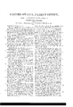
Be it known that I, H. F. VANDENHOVE, of the city, county, and State of New York, have invented a new and Improved Folding Iron Bedstead; and I do hereby declare that the following is a full, clear, and exact description of the same, reference being had to the annexed drawings, making a part of this specification, in which- Figure l, is a side view of my improvement extended. Fig. 2, is a side view of the same, in a folded state. Fig. 3, is a transverse vertical section of the same, taken in the line Fig. l. Fig. 4 is a plan or top View of the same. Fig. 5 is an inner side view of a portion of one of the posts and side pieces.
Similar letters of reference indicate corresponding parts in the several figures.
This invention consists in a peculiar mode of applying or attaching side rails or fenders to a bedstead arranged as will be hereinafter shown and described so that the bedstead may be folded and rendered as compact as usual when not in use.
The invention also consists in a novel means for securing the posts in a vertical position when the bedstead is extended.
To enable thoseskilled in the art to fully understand and construct my invention I will proceed to describe it.
The bottom of the bedstead may be described as being formed of two parts A, B, the end pieces of which are connected at their inner ends by rivets or joints (a), to the upper ends of legs C, C, which form when the bedstead is extended the center supports of the bottom, see Figs. 1 and 4. The two parts of the bottom are connected in the usual way, the side pieces having cross bars (o) attached to them, said barshaving thin metal strips (CZ) attached, the latter being parallel with the side pieces (Z9) as shown in Fig. 4.
To .the outer ends of the parts A, B, posts D are attached. These posts are connected by cross or tie-rods (e) (e) and the outer ends of the side pieces (ZJ) (b) of the parts A, B, are fitted loosely on the lower cross or tie-rods (e), so that the parts A, B, may be moved 0r turnedupward in a vertical or nearly vertical position as shown in Fig. 2, the legs C, C, being of course also elevated, but remaining in a vertical position.
18,565, dated November 3, 1857.
Zhen the two parts A, B, are extended it is essential that the posts D be retained in a vertical position. This is effected by means of buttons (f) which are pivoted to the outer surfaces of the side pieces (b) as shown at (g), and also by means of pins (f) attached to the outer ends of the side pieces (5) said pins being fitted in segment grooves in the inner side of the posts, see Fig. 5. The buttons fit in curved recesses (7L) in the inner edges of the posts and retain them in a vertical position. This will be understood by referring to Fig. l. The buttons (f) are adjusted or operated by hand, being moved upward and turned out from the curved recesses (ZL) when the bedstead is to be folded.
To the inner side of each side piece (Zn) two eyes are attached. These eyes form bearings for rods (j), the ends of which fit in said eyes, there being a rod (j) to each side piece. The rods (j) have bars (7c) attached to them at right angles, and the outer ends of the bars are secured to rods (Z) which are parallel with the rods (j). The rods bars (Z6) and rods (Z) form side rails guards or fenders to the bedstead, two being attached to each of the parts A, B, one at each side. The ends of the rods (j) are allowed to turn freely in their eyes or bearings and consequently each side rail or guard may be turned over flatwise on the part A, or B, to which it is attached so as to allow the parts to be folded as compactly as usual. The side rails however are retained in a vertical position when the bedstead is extended by having a notch (m) cut in the outer end of each rod, said notches when the side pieces are elevated fitting over catches or projections attached to the upper parts ofthe posts D as shown in Figs. l, 3 and 4. The inner ends of the rods (Z) are secured together when the side pieces or guards are raised in a vertical position by having a Hat knob or turnplate (0) attached to the inner end of one of the rods (Z) at each side of the bedstead, and having an oblong slot made through the ends of the adjoining rods, the plates (o) being passed through the slots and then turned in order to secure the two rods at each side of the bedstead together.
By the above improvement the side rails are applied to the bedstead so as not to prevent its being folded less compactly than usual, and the posts D by means of the buttons (f) and the curved grooves and pins are secured firmly in a Vertical position and the buttons may be adjusted With the greatest facility.
I do not claim broadly a bedstead connected by joints so that When not in use the parts may be folded together, as such bedsteads are Well known and in quite common use; neither do I claim separately or in themselves considered the guards or fenders independent of the manner in Which they are arranged or applied to the bedstead,
15 but,
Publications (1)
| Publication Number | Publication Date |
|---|---|
| US18565A true US18565A (en) | 1857-11-03 |
Family
ID=2081986
Family Applications (1)
| Application Number | Title | Priority Date | Filing Date |
|---|---|---|---|
| US18565D Expired - Lifetime US18565A (en) | Iron bedstead |
Country Status (1)
| Country | Link |
|---|---|
| US (1) | US18565A (en) |
Cited By (1)
| Publication number | Priority date | Publication date | Assignee | Title |
|---|---|---|---|---|
| US4460059A (en) * | 1979-01-04 | 1984-07-17 | Katz Lewis J | Method and system for seismic continuous bit positioning |
-
0
- US US18565D patent/US18565A/en not_active Expired - Lifetime
Cited By (1)
| Publication number | Priority date | Publication date | Assignee | Title |
|---|---|---|---|---|
| US4460059A (en) * | 1979-01-04 | 1984-07-17 | Katz Lewis J | Method and system for seismic continuous bit positioning |
Similar Documents
| Publication | Publication Date | Title |
|---|---|---|
| US5863A (en) | Matthias p | |
| US18565A (en) | Iron bedstead | |
| US25508A (en) | Tailor s shears | |
| US21157A (en) | Folding gridiron | |
| US14668A (en) | Marshall lbfferts | |
| US13034A (en) | Bedstead | |
| US25737A (en) | Clothes-ekame | |
| US19724A (en) | Post fob field-fences | |
| US25695A (en) | Chapman warner | |
| US18636A (en) | Extension-table | |
| US15514A (en) | hayes | |
| US20092A (en) | Bedstead-bail | |
| US71804A (en) | Samuil a | |
| US29811A (en) | Qtjilting-eb | |
| US25773A (en) | Milk-safe | |
| US23379A (en) | William h | |
| US26183A (en) | Carriage-top | |
| US20664A (en) | Improved cabinet for sewing-machines | |
| US25577A (en) | Bed-spring | |
| US17191A (en) | Adjustable pole | |
| US16635A (en) | Extension-chair | |
| US16336A (en) | Improvement in traveling-trunks | |
| US25563A (en) | Bedstead | |
| US12833A (en) | Charles r | |
| US16598A (en) | Eence adaptable to uneven ground |