US1854850A - Roasting apparatus - Google Patents
Roasting apparatus Download PDFInfo
- Publication number
- US1854850A US1854850A US389501A US38950129A US1854850A US 1854850 A US1854850 A US 1854850A US 389501 A US389501 A US 389501A US 38950129 A US38950129 A US 38950129A US 1854850 A US1854850 A US 1854850A
- Authority
- US
- United States
- Prior art keywords
- spindles
- furnace
- carrier
- trap
- articles
- Prior art date
- Legal status (The legal status is an assumption and is not a legal conclusion. Google has not performed a legal analysis and makes no representation as to the accuracy of the status listed.)
- Expired - Lifetime
Links
Images

Classifications
-
- A—HUMAN NECESSITIES
- A47—FURNITURE; DOMESTIC ARTICLES OR APPLIANCES; COFFEE MILLS; SPICE MILLS; SUCTION CLEANERS IN GENERAL
- A47J—KITCHEN EQUIPMENT; COFFEE MILLS; SPICE MILLS; APPARATUS FOR MAKING BEVERAGES
- A47J37/00—Baking; Roasting; Grilling; Frying
- A47J37/04—Roasting apparatus with movably-mounted food supports or with movable heating implements; Spits
- A47J37/046—Roasting apparatus with movably-mounted food supports or with movable heating implements; Spits with horizontal turntables
Definitions
- This invention relates to roasting apparatus and more particularly to an oven and means for transporting fruit and vegetables for the purpose of loosening the skins of such articles to facilitate their removal. More particularly the invention relates to a simplified construction for heating pimientos in order that the skin may be loosened from the useful part of the vegetable and more readily re- 1 moved therefrom.
- An object. of the invention is to provide a simplified construction by which the pimientos or like articles may be readily carried through the roasting furnace and then discharged for further operations.
- Another object of the invention consists of an automatic means by which the spindles or spikes on which the pimientos are mounted may be raised and lower-ed for removing the pimientos therefrom after they have been carried out of the furnace.
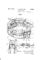
- Figure 2 is a vertical sectional View taken on the line 2-2 of Figure 1 and looking in 30 the direction of the arrows.
- Figure 3 is a fragmentary side elevational View of the apparatus looking from a point within the annular frame work of the structure; parts being shown in section.
- Figure 1 is a fragmentary plan view of the trap for disengaging the roasted articles from their carrying means; parts being broken away for the purpose of more clearly illustrating the construction; and
- Figure 5 is a detail sectional view through the furnace showing the means for raising the pimientos as they enter the furnace.
- the numeral 1 indicates the base of the frame work of the apparatus on which are fastened a plurality. of brackets 2 provided with bearings 3. In these bearings are mounted rollers 4. These rollers are preferably arranged in pairs spaced apart and forming the traveling support for the carrier about to be described.
- This furnace 7 is of substantially inverted U-shaped construction and is formed of any preferred refractory material.
- the furnace is of substantially semi-circular outline and has extending above the top thereof a pipe 8 provided with branches 9 extending downwardly through the top of the furnace to the interior thereof.
- This pipe is in communication with the main feed pipe 10 provided with a control valve 11, and by this means gas, oil, or other fuel is fed to the burners mounted within the furnace and associated with the inner ends of the branches 9.
- additional valves may be placed on each of these branches 9 if desired, for the purpose of controlling or modifying the temperature in different zones within the furnace.
- annular plate 12 Disposed below the open lower end of the furnace 7 is an annular plate 12. Bolted to the lower side of this plate at the inner and outer edges thereof are angle irons 13, the lower edges of which rest upon the rollers 4 heretofore referred to.
- a rack 14 bolted to the inner angle iron 13, and cooperating with this rack are pinions 15.
- pinions are mounted on the inner ends of shafts 16 which have their bearings in brackets 17 mounted on the base member 1.
- pulley wheels or the like 18 are also mounted on the shafts 16 to which may be imparted a rotative movement by a belt or the like as indicated in dotted outline.
- This trap is provided with two slots may be imparted to the carrier 12 to transport any articles mounted thereon through the furnace 7. While the driving mechanism shown consists of a belt, it will be obvious that any other conventional means for imparting a rotary movement to the pinions 15 may be employed if preferred.
- Formed in the carrier plate 12 are two annular series of openings preferably staggered, and provided with bushings or bearings 21 in which are mounted a plurality of upright spindles or spikes 22. These spindles are provided with collars 23 adjacent their upper pointed ends 24 which serve as stops or limits for the downward movement of the spindles through the carrier plate 12.
- a trap 28 disposed directly above the carrier plate just beyond the exit end of the furnac7e 2 7 the walls of which converge from the discharge end of the furnace, and are disposed directly above the downwardly inclined portion 26 of the platform 26. Consequently as the weights or spherical members 25 pass off of the horizontal portion 26 of the platform, the spindles 22 will be gradually lowered until the collars 23 contact the upper surface of the plate 12. Therefore, inasmuch as the narrow ends of the slots 27 are of a less width than the articles carried on the spikes or spindles 22 they will be disengaged from the spindles as the latter descend through the slots.
- the trap plate is provided with a downwardly inclined chute or the like 30 by means of which the articles are carried to a receptacle properly positioned with respect to the chute.
- the articles as they are released from the spindles may be projected over onto the chute, I have provided'an inner wall 31 on the trap which is inclined toward the chute 30 and will thus tend to force the articles in that direction, and thus prevent the undue accumulation thereof on the trap plate.
- an attendant will manually place the pimientos, or other vegetable or fruit, upon the sharpened ends 24: of the spikes or spindles as they approach the entrance end of the furnace in their lowered positions.
- the flames from the burners will roast them to a sufficient degree to loosen the skins which it is desired to be removed, and as previously noted the degree of heat through the length of the furnace may be suitably varied by properly adjusting the valves of the burners.
- the roasted articles leave the exit end of the furnace they are lowered by reason of the weights 25 riding down the incline 26.
- a roasting machine including an arouate roasting chamber open at its lower end, a rotatably mounted annular sheet metal carrier, upright spindles mounted on said carrier and adapted to have their upper ends pass through said roasting chamber, means for rotating said carrier, and means for removing articles carried on said spindles.
- a roasting machine including an arcuate roasting chamber open at its lower end, an annular sheet metal carrier, rollers on which said carrier is mounted, a plurality of spindles mounted on said carrier and adapted to have their upper ends pass through said roasting chamber, and a rack and pinion for rotating said carrier.
- a roasting machine including an arcuate roasting chamber open at its lower end, an annular sheet metal carrier, rollers on which said carrier is mounted, a plurality of spin dles mounted on said carrier and adapted to have their upper ends pass through said roasting chamber, a rack and pinion for rotating said carrier, and means engaging the upper surface of said carrier for maintaining said rack and pinion in mesh.
- a roasting machine including a furnace, a carrier disposed adjacent said furnace, a plurality of upright spindles mounted on said carrier for vertical movement, means for raising and lowering said spindles, and a trap into which the upper ends of said spindles are projected when in raised position.
- a roasting machine including a furnace, a plurality of vertically reciprocable spindles adapted to pass through said furnace, a slotted trap for removing articles carried by said spindles, said trap comprising a slotted plate, means for raising said spindles prior to bringing them into cooperative relation to said trap, and means for lowering said spindles after being brought into cooperative relation with said trap.
- a roasting machine including a furnace, a plurality of vertically reciprocable spindles adapted to pass through said furnace, a slotted trap for removing articles carried by said spindles, said trap comprising a slotted plate, means for raising said spindles prior to bringing them into cooperative relation to said trap, means for lowering said spindles after being brought into cooperative relation with said trap, and a downwardly inclined extension on said trap to transport articles removed from the spindle to a receptacle.
- a roasting machine including an arcuate roasting chamber open at its lower end a rotatably mounted carrier, upright spindles slidably mounted on said carrier for vertical movement and adapted to have their upper ends pass through said roasting chamber, a platform disposed below the open lower end of said chamber and upon which the spindles are adapted to ride as they travel through the chamber, inclined ends on said platform for raising said spindles and for allowing them to be lowered to normal position, and a trap adjacent the exist end of the chamber for disengaging articles carried on said spindles.
- a roasting machine including an arcuate roasting chamber open at its lower end, a rotatably mounted carrier, upright spindles slidably and rotatably mounted on said carrier and adapted to have their upper ends pass through said roasting chamber, a platform disposed below the open lower end of said chamber and upon which the spindles are adapted to ride as they travel through the chamber, and means for rotating said spindles while passing through the chamber.
Landscapes
- Engineering & Computer Science (AREA)
- Food Science & Technology (AREA)
- Drying Of Solid Materials (AREA)
Description
April 19,1932. M. M. LINKENAUGER ROASTING APPARATUS 2 Sheets-Sheet 1 Filed Aug. 30, 1929 3nnentor JZM lz'nkenauger attorney" April 19, 1932. M. M. LINKENAUGER ROASTING APPARATUS Filed Aug. 30, 1929 2 Sheets-Sheet 2 Gttornegs Patented Apr. 19, 1932 PATENT OFFICE MONT M. LINKENAUGER, OF SUMTER, SOUTH GAROLINA.
ROASTING APPARATUS Application filed August 30, 1929. Serial No. 389,501.
This invention relates to roasting apparatus and more particularly to an oven and means for transporting fruit and vegetables for the purpose of loosening the skins of such articles to facilitate their removal. More particularly the invention relates to a simplified construction for heating pimientos in order that the skin may be loosened from the useful part of the vegetable and more readily re- 1 moved therefrom.
An object. of the invention is to provide a simplified construction by which the pimientos or like articles may be readily carried through the roasting furnace and then discharged for further operations.
Another object of the invention consists of an automatic means by which the spindles or spikes on which the pimientos are mounted may be raised and lower-ed for removing the pimientos therefrom after they have been carried out of the furnace.
Other objects and advantagesof the invention will be apparent from the following description when taken in connection with the V accompanying drawings, in which Figure 1 is a perspective View of the complete apparatus.
Figure 2 is a vertical sectional View taken on the line 2-2 of Figure 1 and looking in 30 the direction of the arrows.
Figure 3 is a fragmentary side elevational View of the apparatus looking from a point within the annular frame work of the structure; parts being shown in section.
Figure 1 is a fragmentary plan view of the trap for disengaging the roasted articles from their carrying means; parts being broken away for the purpose of more clearly illustrating the construction; and
Figure 5 is a detail sectional view through the furnace showing the means for raising the pimientos as they enter the furnace.
Referring to the drawings in greater de- 5 tail, the numeral 1 indicates the base of the frame work of the apparatus on which are fastened a plurality. of brackets 2 provided with bearings 3. In these bearings are mounted rollers 4. These rollers are preferably arranged in pairs spaced apart and forming the traveling support for the carrier about to be described.
Also supported on the base 1 are a plurality of inverted U-shaped standards or brackets 5 to which are bolted arcuate angle irons 6 which form supports for the furnace or oven 7. This furnace 7 is of substantially inverted U-shaped construction and is formed of any preferred refractory material. As will be noted from an examination of Figure 1 the furnace is of substantially semi-circular outline and has extending above the top thereof a pipe 8 provided with branches 9 extending downwardly through the top of the furnace to the interior thereof. This pipe is in communication with the main feed pipe 10 provided with a control valve 11, and by this means gas, oil, or other fuel is fed to the burners mounted within the furnace and associated with the inner ends of the branches 9. Obviously additional valves may be placed on each of these branches 9 if desired, for the purpose of controlling or modifying the temperature in different zones within the furnace.
Disposed below the open lower end of the furnace 7 is an annular plate 12. Bolted to the lower side of this plate at the inner and outer edges thereof are angle irons 13, the lower edges of which rest upon the rollers 4 heretofore referred to. For the purpose of imparting a rotative movement to the annular plate or carrier 12 a rack 14: bolted to the inner angle iron 13, and cooperating with this rack are pinions 15. These pinions are mounted on the inner ends of shafts 16 which have their bearings in brackets 17 mounted on the base member 1. Also mounted on the shafts 16 are pulley wheels or the like 18 to which may be imparted a rotative movement by a belt or the like as indicated in dotted outline.
A second bearing 19 disposed above the car- .7. This trap is provided with two slots may be imparted to the carrier 12 to transport any articles mounted thereon through the furnace 7. While the driving mechanism shown consists of a belt, it will be obvious that any other conventional means for imparting a rotary movement to the pinions 15 may be employed if preferred.
Formed in the carrier plate 12 are two annular series of openings preferably staggered, and provided with bushings or bearings 21 in which are mounted a plurality of upright spindles or spikes 22. These spindles are provided with collars 23 adjacent their upper pointed ends 24 which serve as stops or limits for the downward movement of the spindles through the carrier plate 12. Formed or secured on the lower ends of the spindles 22 are Weights preferably of spherical form and which are adapted to normally retain the spindles in their lowermost position with their collars 23 in engagement with the upper surface of the plate 12.
It will be readily understood that it is intended to place the pimientos or other fruit or vegetable, the skin of which is to be lo0sened, on the sharpened ends 24 of the spin dles 22 prior to their entrance into the furnace 7. It is also desirable to rotate the articles as they travel through the furnace, and to facilitate this operation as well as to permit the removal of the articles from the spikes, I provide an arcuate platform 26 below the furnace 7, by means of which the spikes are raised and lowered respectively as they enter and leave the furnace. For the purpose of rotating the spindles or spikes 22f a'bar or bars 29 biased against the spherical weights 25 by springs 29 are provided. Obviously, as the spindles are carried through the furnace on plate 12 they will be caused to rotate about their respective axes by reason of frictional contact between the bar 29 and the spherical members 25, which are fixedly secured to the spindles.
For the purpose of removing these articles from the ends of the spindles after leaving the furnace I provide what may be termed a trap 28 disposed directly above the carrier plate just beyond the exit end of the furnac7e 2 7 the walls of which converge from the discharge end of the furnace, and are disposed directly above the downwardly inclined portion 26 of the platform 26. Consequently as the weights or spherical members 25 pass off of the horizontal portion 26 of the platform, the spindles 22 will be gradually lowered until the collars 23 contact the upper surface of the plate 12. Therefore, inasmuch as the narrow ends of the slots 27 are of a less width than the articles carried on the spikes or spindles 22 they will be disengaged from the spindles as the latter descend through the slots.
It. is desirable, .of course, that some automatic means be provided for projecting the finished articles from the trap plate in order to avoid congestion of this part of the mechanism, and to this end the trap plate is provided with a downwardly inclined chute or the like 30 by means of which the articles are carried to a receptacle properly positioned with respect to the chute. In order, also, that the articles as they are released from the spindles may be projected over onto the chute, I have provided'an inner wall 31 on the trap which is inclined toward the chute 30 and will thus tend to force the articles in that direction, and thus prevent the undue accumulation thereof on the trap plate.
In the operation of the device an attendant will manually place the pimientos, or other vegetable or fruit, upon the sharpened ends 24: of the spikes or spindles as they approach the entrance end of the furnace in their lowered positions. As the articles are carried through the furnace the flames from the burners will roast them to a sufficient degree to loosen the skins which it is desired to be removed, and as previously noted the degree of heat through the length of the furnace may be suitably varied by properly adjusting the valves of the burners. As the roasted articles leave the exit end of the furnace they are lowered by reason of the weights 25 riding down the incline 26. It will be understood that prior to this lowering movement the pimientos are spaced above the narrow ends of the slots 27, so that as the spindles ride down the incline 26 of the platform they are withdrawn from the roasted product, and as heretofore men tioned the latter are caused to descend over the chute 30 into a receptacle suitably disposed with relation to the lower end thereof. The skins as thus loosened may be readily removed in any conventional manner.
From the foregoing description taken in connection with the accompanying drawings it will be apparent to those skilled in the art that I have provided a very simple and lI16X- pensive construction of roasting apparatus for vegetables and fruit, which contains very few parts, is simply operated with little or no liability of becoming disorganized in operation; and that the article carrying spindles are automatically raised and rotated as they pass through the furnace and are then lowered for cooperation with a trap by means of which the roasted articles are automatically discharged from the apparatus and .conveyed to any suitable receptable or point of destination.
In accordance with the patent statutes I have described what I now believe to be the preferred form of the inventionbut it will be understood that various minor changes or modifications in the details of construction may be made without in any way departing from the spirit of the invention, and it is therefore intended thatthe drawings be considered as illustrative of the invention rather than in any limiting sense, and all such changes or modifications in details are intended to be included within the scope of the appended claims.
Having fully described my invention what I claim as new and desire to secure by Letters Patent is 1. A roasting machine including an arouate roasting chamber open at its lower end, a rotatably mounted annular sheet metal carrier, upright spindles mounted on said carrier and adapted to have their upper ends pass through said roasting chamber, means for rotating said carrier, and means for removing articles carried on said spindles.
2. A roasting machine including an arcuate roasting chamber open at its lower end, an annular sheet metal carrier, rollers on which said carrier is mounted, a plurality of spindles mounted on said carrier and adapted to have their upper ends pass through said roasting chamber, and a rack and pinion for rotating said carrier.
3. A roasting machine including an arcuate roasting chamber open at its lower end, an annular sheet metal carrier, rollers on which said carrier is mounted, a plurality of spin dles mounted on said carrier and adapted to have their upper ends pass through said roasting chamber, a rack and pinion for rotating said carrier, and means engaging the upper surface of said carrier for maintaining said rack and pinion in mesh.
4. A roasting machine including a furnace, a carrier disposed adjacent said furnace, a plurality of upright spindles mounted on said carrier for vertical movement, means for raising and lowering said spindles, and a trap into which the upper ends of said spindles are projected when in raised position.
5. A roasting machine including a furnace, a plurality of vertically reciprocable spindles adapted to pass through said furnace, a slotted trap for removing articles carried by said spindles, said trap comprising a slotted plate, means for raising said spindles prior to bringing them into cooperative relation to said trap, and means for lowering said spindles after being brought into cooperative relation with said trap.
6. A roasting machine including a furnace, a plurality of vertically reciprocable spindles adapted to pass through said furnace, a slotted trap for removing articles carried by said spindles, said trap comprising a slotted plate, means for raising said spindles prior to bringing them into cooperative relation to said trap, means for lowering said spindles after being brought into cooperative relation with said trap, and a downwardly inclined extension on said trap to transport articles removed from the spindle to a receptacle.
7. A roasting machine including an arcuate roasting chamber open at its lower end a rotatably mounted carrier, upright spindles slidably mounted on said carrier for vertical movement and adapted to have their upper ends pass through said roasting chamber, a platform disposed below the open lower end of said chamber and upon which the spindles are adapted to ride as they travel through the chamber, inclined ends on said platform for raising said spindles and for allowing them to be lowered to normal position, and a trap adjacent the exist end of the chamber for disengaging articles carried on said spindles.
8. A roasting machine including an arcuate roasting chamber open at its lower end, a rotatably mounted carrier, upright spindles slidably and rotatably mounted on said carrier and adapted to have their upper ends pass through said roasting chamber, a platform disposed below the open lower end of said chamber and upon which the spindles are adapted to ride as they travel through the chamber, and means for rotating said spindles while passing through the chamber.
MONT M. LINKENAUGER.
Priority Applications (1)
| Application Number | Priority Date | Filing Date | Title |
|---|---|---|---|
| US389501A US1854850A (en) | 1929-08-30 | 1929-08-30 | Roasting apparatus |
Applications Claiming Priority (1)
| Application Number | Priority Date | Filing Date | Title |
|---|---|---|---|
| US389501A US1854850A (en) | 1929-08-30 | 1929-08-30 | Roasting apparatus |
Publications (1)
| Publication Number | Publication Date |
|---|---|
| US1854850A true US1854850A (en) | 1932-04-19 |
Family
ID=23538507
Family Applications (1)
| Application Number | Title | Priority Date | Filing Date |
|---|---|---|---|
| US389501A Expired - Lifetime US1854850A (en) | 1929-08-30 | 1929-08-30 | Roasting apparatus |
Country Status (1)
| Country | Link |
|---|---|
| US (1) | US1854850A (en) |
Cited By (21)
| Publication number | Priority date | Publication date | Assignee | Title |
|---|---|---|---|---|
| US2417063A (en) * | 1943-08-05 | 1947-03-11 | Cold Metal Products Company | Rotating annular hearth annealing furnace |
| US2556808A (en) * | 1948-03-11 | 1951-06-12 | James M Harris | Barbecue broiler |
| US2561538A (en) * | 1948-08-24 | 1951-07-24 | Rudolph A Schultz | Machine for cooking frankfurters, buns, and the like |
| US2608178A (en) * | 1947-09-04 | 1952-08-26 | Benjamin M Kolber | Circular poultry house |
| US2622861A (en) * | 1950-03-08 | 1952-12-23 | Randal E Talley | Rotary hearth furnace |
| US2718188A (en) * | 1955-09-20 | Automatic hamburger preparing apparatus | ||
| US2868252A (en) * | 1955-12-20 | 1959-01-13 | Richard C Boucher | Apparatus for and process of removing skins from tomatoes |
| US2928524A (en) * | 1957-02-18 | 1960-03-15 | Frank V Jensen | Food broiling oven |
| US3095832A (en) * | 1958-06-18 | 1963-07-02 | George W Evans | Pie forming apparatus |
| US3126113A (en) * | 1964-03-24 | Kaper | ||
| US3190475A (en) * | 1961-10-02 | 1965-06-22 | Int Harvester Co | Tractor supported implement mounting |
| US3333529A (en) * | 1963-12-20 | 1967-08-01 | Robert G Wilson | Oven supports |
| US3361054A (en) * | 1966-10-31 | 1968-01-02 | Lampe | Food processing machine |
| US3777752A (en) * | 1972-04-03 | 1973-12-11 | R Goodwin | Chick processing and handling device |
| US4315950A (en) * | 1971-10-18 | 1982-02-16 | International Food Equipment, Inc. | Method for cooking hamburger patties |
| US4446775A (en) * | 1971-10-18 | 1984-05-08 | International Food Equipment, Inc. | Apparatus for heating food products |
| US4539900A (en) * | 1971-10-18 | 1985-09-10 | International Food Equipment, Inc. | Apparatus for heating food products |
| US4831923A (en) * | 1986-10-01 | 1989-05-23 | Nestec S.A. | Cored food filling apparatus |
| US5712466A (en) * | 1995-10-30 | 1998-01-27 | Spicer; James T. | Perfect steak device |
| US10624353B1 (en) * | 2015-03-12 | 2020-04-21 | John Langley | Pizza oven |
| US11224228B1 (en) | 2020-06-18 | 2022-01-18 | John Langley | Three sensor oven |
-
1929
- 1929-08-30 US US389501A patent/US1854850A/en not_active Expired - Lifetime
Cited By (21)
| Publication number | Priority date | Publication date | Assignee | Title |
|---|---|---|---|---|
| US2718188A (en) * | 1955-09-20 | Automatic hamburger preparing apparatus | ||
| US3126113A (en) * | 1964-03-24 | Kaper | ||
| US2417063A (en) * | 1943-08-05 | 1947-03-11 | Cold Metal Products Company | Rotating annular hearth annealing furnace |
| US2608178A (en) * | 1947-09-04 | 1952-08-26 | Benjamin M Kolber | Circular poultry house |
| US2556808A (en) * | 1948-03-11 | 1951-06-12 | James M Harris | Barbecue broiler |
| US2561538A (en) * | 1948-08-24 | 1951-07-24 | Rudolph A Schultz | Machine for cooking frankfurters, buns, and the like |
| US2622861A (en) * | 1950-03-08 | 1952-12-23 | Randal E Talley | Rotary hearth furnace |
| US2868252A (en) * | 1955-12-20 | 1959-01-13 | Richard C Boucher | Apparatus for and process of removing skins from tomatoes |
| US2928524A (en) * | 1957-02-18 | 1960-03-15 | Frank V Jensen | Food broiling oven |
| US3095832A (en) * | 1958-06-18 | 1963-07-02 | George W Evans | Pie forming apparatus |
| US3190475A (en) * | 1961-10-02 | 1965-06-22 | Int Harvester Co | Tractor supported implement mounting |
| US3333529A (en) * | 1963-12-20 | 1967-08-01 | Robert G Wilson | Oven supports |
| US3361054A (en) * | 1966-10-31 | 1968-01-02 | Lampe | Food processing machine |
| US4315950A (en) * | 1971-10-18 | 1982-02-16 | International Food Equipment, Inc. | Method for cooking hamburger patties |
| US4446775A (en) * | 1971-10-18 | 1984-05-08 | International Food Equipment, Inc. | Apparatus for heating food products |
| US4539900A (en) * | 1971-10-18 | 1985-09-10 | International Food Equipment, Inc. | Apparatus for heating food products |
| US3777752A (en) * | 1972-04-03 | 1973-12-11 | R Goodwin | Chick processing and handling device |
| US4831923A (en) * | 1986-10-01 | 1989-05-23 | Nestec S.A. | Cored food filling apparatus |
| US5712466A (en) * | 1995-10-30 | 1998-01-27 | Spicer; James T. | Perfect steak device |
| US10624353B1 (en) * | 2015-03-12 | 2020-04-21 | John Langley | Pizza oven |
| US11224228B1 (en) | 2020-06-18 | 2022-01-18 | John Langley | Three sensor oven |
Similar Documents
| Publication | Publication Date | Title |
|---|---|---|
| US1854850A (en) | Roasting apparatus | |
| US1981641A (en) | Bottle handling apparatus | |
| US1835190A (en) | Machine for operating on fruits and the like | |
| US1614056A (en) | Canning machine | |
| US1310495A (en) | Automatic cooker | |
| US1927847A (en) | Mill table | |
| US1778267A (en) | Conveyer | |
| US2000273A (en) | Sheet piling mechanism | |
| US2924325A (en) | Elevators for lifting articles or workpieces | |
| DE2400949A1 (en) | OVEN | |
| CN107348452A (en) | A kind of fast food production line on peanut | |
| US1391212A (en) | Doughnut forming and cooking machine | |
| US2704605A (en) | dahlman | |
| US2017046A (en) | Doughproofing machine | |
| US3000162A (en) | Pallet box filler | |
| US1857492A (en) | Method and apparatus for completing pressed blown ware or blown ware | |
| US1488973A (en) | Method of and means for manufacturing teacups, breakfast cups, and other vessels or articles of pottery | |
| US1857491A (en) | Method and apparatus for completing pressed blown ware or blown ware | |
| US1812976A (en) | Conveying apparatus | |
| US2684681A (en) | Conveyer and quench tank for heat treating furnaces | |
| US1985942A (en) | Production of castings or the like | |
| US1118182A (en) | Device for forming and baking food products. | |
| US1595439A (en) | Preparation of dough for the making of bread | |
| US2713944A (en) | Combination cherry stemmer and sorter | |
| US1708137A (en) | Fruit-grading machine |