US1853514A - Electric lamp - Google Patents
Electric lamp Download PDFInfo
- Publication number
- US1853514A US1853514A US403613A US40361329A US1853514A US 1853514 A US1853514 A US 1853514A US 403613 A US403613 A US 403613A US 40361329 A US40361329 A US 40361329A US 1853514 A US1853514 A US 1853514A
- Authority
- US
- United States
- Prior art keywords
- socket
- holder
- lamp
- reflector
- ribs
- Prior art date
- Legal status (The legal status is an assumption and is not a legal conclusion. Google has not performed a legal analysis and makes no representation as to the accuracy of the status listed.)
- Expired - Lifetime
Links
Images

Classifications
-
- F—MECHANICAL ENGINEERING; LIGHTING; HEATING; WEAPONS; BLASTING
- F21—LIGHTING
- F21S—NON-PORTABLE LIGHTING DEVICES; SYSTEMS THEREOF; VEHICLE LIGHTING DEVICES SPECIALLY ADAPTED FOR VEHICLE EXTERIORS
- F21S41/00—Illuminating devices specially adapted for vehicle exteriors, e.g. headlamps
- F21S41/10—Illuminating devices specially adapted for vehicle exteriors, e.g. headlamps characterised by the light source
- F21S41/19—Attachment of light sources or lamp holders
- F21S41/194—Bayonet attachments
Definitions
- My invention relates to lamp assembly structures which employ lamp receiving sockets and holders for the sockets, more particularly for automobile headlights.
- the invention is of particular importance where such a headlight is equippedwith a concave reflector which carries the holder whose bore is in register with an opening provided through the reflector.
- the invention has for its general object the provision of means whereby thelamp may be fixed with respect to said holder and, where the headlight is equipped with a reflector, may be fixed with respect to the latter element, also.
- the invention finds particular use in connection with headlights having parabolic reflectors and enablesthe fixed relationship of the lamp filament with respect to the parabolic axis on which the filament is preferably located.
- a headlight 29 thus constructed will'direct light in a fixed path with respect to the axis of the reflector, thereby avoiding difficulty now frequently encountered in the adaptation. of reflecting headlights to automotive vehicles, bodily or or other adjustment of the lamps having frequently been required when the users happen to find that the light is improperly directed.
- the structure of my invention is inclusive of asocket holder, a lamp receiving socket 39 within said holder and smaller in cross section than the holder, and means pressing the socket laterally against one'side of the holder.
- thesocket holder is fixed with respect to the reflector and has its bore in register with an opening that is formed through the reflector to permit of the insertion of the base of an incandescent lamp.
- this opening therethrough is usually provided in the crown of the reflector and on the re flector axis.
- 1 provide spaced apart spacing means intervening between the hold-' er and socket in the place at which the sock et is pressed against the holder. These spacing means are desirably in the form of ribs which extend along the holder and socket.
- the meansfor pressing the socket laterally against one side of the holder is desirably in the form of a spring or a pair of springs ,integralwith the holder.
- the pressing means exerts pressure initially against the base of the "inserted lamp, and through this lamp base, against. the lamp socket to press the lamp socket against the holder, whereby all of these elements are maintained in fixed relation. If the holder be associated with a reflector, the position of the lamp filament with respect to the reflector is assured, it being understood that the lamp filaments of the incandescent'lamps which are to be used in thestructures of my invention preferably occupy predetermined uniform positions with respect to the lamp bases.
- I desirably provide V-shaped seats in the bayonet slots that receive the bayonet pins upon the lamps, so that the lamps are brought to a uniform position rotatively.
- the lamp socket in the structure of my invention, is preferably .pre vented from having any longitudinal adjustment, so that the spacing of the lamp filament from the reflector is fixedly determined.
- Fig. 5 is a sectional view on line'55 of Fig. 4';
- Fig. 6 is a sectional view on line 66 of Fig. i;
- Fig. 7 is a perspective view illustrating component parts of the structure in separated relation; and
- Fig. 8 is a sectional elevation taken through the axis of the parabolic reflector.
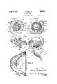
- the headlight illustrated includes a housing or back element 1 having a bracket 2 on its bottom side by which it may be assembled with the automotive vehicle or other sup has its forward end passed through a circular opening formed through the crown of the reflector, in the embodiment of the invention shown.
- the forward end of the holder 9 is formed with flanges 10 and 11 between which 7 the surrounding edge portion ofthe reflector is clamped, Wherebythe holder and reflector are maintained coaxial, in the structure illustrated/
- This socket is preferably formed with a single bayonet slot or channel 13 for receiving a bayonet pin or projection 14 upon the base 15 of an incandescent lamp.
- This bayonet pin is maintained in a V-shaped retaining seat 13 of the bayonet slot by any suitable means, the V-shaped seat holding the lamp from rotati've movement.
- the means illustrated is inclusive of a coiled spring 16 which surrounds a plunger 17 constituting a circuit terminal'and presses forwardly upon the plunger head 18 andrearwardlyupon the flange 19 of a metallic guiding sleeve 20.
- This guiding sleeve is mounted upon an insulating disc .21 which is fixedly assembled with and within the rear end of the socket 12.
- the plunger head 18 presses against a contact 22 which is carried by the generally cylindri' movement, whereby the position of the filacal lamp base 15 which is made of insulating material.
- the lamp structure illustrated is a so-called single pole, though the invention is not to be thus limited.
- the contact 22 is upon the axis of the lamp base.
- a stiff leading in wire 24 establishes connection between the contact 22 and one terminal of the filament 25.
- Another stiff leading in wire 26 estab-. lishe-s a connection between the other termi-" nal of the filament andthe' metallic sheath 27 which surrounds the insulating portion of the lamp base and, from the point of view of my invention, also constitutes a part or enlargement of the lamp base.
- the body of the reflector, the holder 9, and'the socket 12' aregrounded and when the lamp is in place the sheath 27 is also grounded asit has connection with the holder, as will more fully appear.
- the cross section of the socket 12 is smaller than the bore of the holder 9 and the base ofthe lamp, in-
- These spacing means are preferably in the form of ribs 28 which extend along the holder and socket.
- Each rib isdesirably integrally formed with one of the elements 9 or 12, both ribs being shown. as being integrally formed with the holder.
- the ribs are spaced less than 180 degrees apart, preferably 120 degrees apart.
- the means for pressing the socket laterally against the holder presses the socket against these ribs so that the axis of the socket bears a fixed relation to the ribs and to the axis of the reflector that carries the holder. Pressure is exerted on a diametrical line that passes between the ribs.
- Means for exerting the pressure is desirably in the form of two spring tongues which are integrally formed with the holder.
- the free or unattached ends of these tongues are inwardly turned to an extent which causes these tongues to be outwardly flexed, when the socket is inserted, so that the tongues will exert the desired pressure upon the socket.
- This pressure upon the socket is desirably exerted throughthe intermediation of the lamp base whose metallic sheath portion is engaged by the tongues, the electrical connection of the sheath with the grounded elements being also thereby further assured.
- the socket is formed with an opening 30 through which the free ends.
- ment on the reflector axis is fixedly predetermined to avoid special design of the reflector that would be necessary if the'filament were movable along the reflector axis.
- Spaced apart spacing means also intervene between the socket 12 and the lamp base.
- These spacing means are preferably in the form of ribs 31 which extend along the socket and lamp base.
- Each rib is desirably integrally formed with one of the elements 12 or 27, both ribs being shown as being integrally formed with the socket.
- These ribs are also spaced less than 180 degrees apart. preferably 120 degrees apart.
- the free ends of the tongues 29 pressing upon the lamp base not only exert pressure in a line that passes between the ribs 28, but also exert pres sure in a'line that passes between the ribs 31. the two pairs of ribs being substantially in register.
- the filament is upon the axis of the reflector, which is preferably parabolic.
- the lamps which are designed for use in this structure are manufactured with all filaments in the same relative positions to the lamp bases and as the lamps are in this respect similar and in other respects also, they may readily be replaced with the assurance that the filament will come exactly into the right position with respect to the reflector when any lamp is inserted within its socket.
- the holder and socket in the :place at which the socket is pressed against the holder; an incandescent lamp having its filament within the reflector and its base within the aforesaid socket, said lamp base being smaller in cross section than the bore of the socket; spaced apart spacing members extending longitudinally of the socket and lamp base and intervening between the socket and lamp base in the place at which the lamp base is pressed against the socket; and means pressing the socket laterally against one side of the afore-- said holder to position the socket with respect to the reflector, said means also pressing the lamp base against one side of the socket to position the lamp filament with respect toboth socket and reflector.
- a lamp receiving socket within said pressed holder and smaller in cross section than the bore of the holder; spacing members extend-. ing longitudinally of the holder and socket and intervening between the holder and socket in the place at which the socket is pressed against the holder, said spacing memline passing diametrically between said spac-' ing members, said means including an element pressing against the internal wall of the socket.
- spaced apart spacing ribs extendping longitudinally of the holder and socket .nd intervening between the holder and socket in the place at which the socket is pressed against the holder; and means pressing the socket laterally against one side of the hold er,'said means including an element pressing against the internal wall of the socket and said means also locking'the socket against longitudinal movement with respect to the holder.
Landscapes
- Engineering & Computer Science (AREA)
- General Engineering & Computer Science (AREA)
- Non-Portable Lighting Devices Or Systems Thereof (AREA)
Description
H. A. DOUGLAS ELECTRIC LAMP April 12, 1932.
-2 Sheets-Sheet Filed Oct. 30, 1929 @ZZ" 0 V g ,2 13/ @2 JazzgZafi April 12, 1932. DQUGLAS 1,853,514
ELECTRIC LAMP Filed Oct. 30, 1929 2 Sheets-Sheet 2 @229 6?. JOagZQfi Patented Apr. 12, 1932 UNETED STATES HARRY A. DOUGLAS, OF BRONSON', MICHIGAN ELECTRIC LAMP Application filed October 30, 1929. Serial No. 403,613.
My invention relates to lamp assembly structures which employ lamp receiving sockets and holders for the sockets, more particularly for automobile headlights. The invention is of particular importance where such a headlight is equippedwith a concave reflector which carries the holder whose bore is in register with an opening provided through the reflector. The invention has for its general object the provision of means whereby thelamp may be fixed with respect to said holder and, where the headlight is equipped with a reflector, may be fixed with respect to the latter element, also. The invention finds particular use in connection with headlights having parabolic reflectors and enablesthe fixed relationship of the lamp filament with respect to the parabolic axis on which the filament is preferably located. A headlight 29 thus constructed will'direct light in a fixed path with respect to the axis of the reflector, thereby avoiding difficulty now frequently encountered in the adaptation. of reflecting headlights to automotive vehicles, bodily or or other adjustment of the lamps having frequently been required when the users happen to find that the light is improperly directed.
The structure of my invention is inclusive of asocket holder, a lamp receiving socket 39 within said holder and smaller in cross section than the holder, and means pressing the socket laterally against one'side of the holder.
In a headlight employing a concave reflector,
thesocket holder is fixed with respect to the reflector and has its bore in register with an opening that is formed through the reflector to permit of the insertion of the base of an incandescent lamp. In a parabolic reflector this opening therethrough is usually provided in the crown of the reflector and on the re flector axis. In order that the axis of the socket may be maintained parallel with the axis of the holder, 1 provide spaced apart spacing means intervening between the hold-' er and socket in the place at which the sock et is pressed against the holder. These spacing means are desirably in the form of ribs which extend along the holder and socket. The meansfor pressing the socket laterally against one side of the holder is desirably in the form of a spring or a pair of springs ,integralwith the holder. In the preferred embodiment of the invention the pressing means exerts pressure initially against the base of the "inserted lamp, and through this lamp base, against. the lamp socket to press the lamp socket against the holder, whereby all of these elements are maintained in fixed relation. If the holder be associated with a reflector, the position of the lamp filament with respect to the reflector is assured, it being understood that the lamp filaments of the incandescent'lamps which are to be used in thestructures of my invention preferably occupy predetermined uniform positions with respect to the lamp bases. To further assure the precise positions of the lamps, I desirably provide V-shaped seats in the bayonet slots that receive the bayonet pins upon the lamps, so that the lamps are brought to a uniform position rotatively. The lamp socket, in the structure of my invention, is preferably .pre vented from having any longitudinal adjustment, so that the spacing of the lamp filament from the reflector is fixedly determined. This construction obviates the necessity of a special design for the reflector which has hitherto been proposed to procure the same lighting effect with the filament in different positions along the reflector axis. The invention, however, is not to be thuslimited.
The invention will be more fully explained in connection with the accompanying draw Fig. 1; Fig. 5 is a sectional view on line'55 of Fig. 4'; Fig. 6 is a sectional view on line 66 of Fig. i; Fig. 7 is a perspective view illustrating component parts of the structure in separated relation; and Fig. 8 is a sectional elevation taken through the axis of the parabolic reflector.
The headlight illustrated includes a housing or back element 1 having a bracket 2 on its bottom side by which it may be assembled with the automotive vehicle or other sup has its forward end passed through a circular opening formed through the crown of the reflector, in the embodiment of the invention shown. The forward end of the holder 9 is formed with flanges 10 and 11 between which 7 the surrounding edge portion ofthe reflector is clamped, Wherebythe holder and reflector are maintained coaxial, in the structure illustrated/ The generally cylindrical lamp socket 12 1s held in assembly with and within the holder 9 by the means hereinafter set forth. This socket is preferably formed with a single bayonet slot or channel 13 for receiving a bayonet pin or projection 14 upon the base 15 of an incandescent lamp. This bayonet pin is maintained in a V-shaped retaining seat 13 of the bayonet slot by any suitable means, the V-shaped seat holding the lamp from rotati've movement. The means illustrated is inclusive of a coiled spring 16 which surrounds a plunger 17 constituting a circuit terminal'and presses forwardly upon the plunger head 18 andrearwardlyupon the flange 19 of a metallic guiding sleeve 20. This guiding sleeve is mounted upon an insulating disc .21 which is fixedly assembled with and within the rear end of the socket 12. The plunger head 18 presses against a contact 22 which is carried by the generally cylindri' movement, whereby the position of the filacal lamp base 15 which is made of insulating material. The lamp structure illustrated is a so-called single pole, though the invention is not to be thus limited. Where a single pole structure is employed, the contact 22 is upon the axis of the lamp base. A stiff leading in wire 24 establishes connection between the contact 22 and one terminal of the filament 25. Another stiff leading in wire 26 estab-. lishe-s a connection between the other termi-" nal of the filament andthe' metallic sheath 27 which surrounds the insulating portion of the lamp base and, from the point of view of my invention, also constitutes a part or enlargement of the lamp base. The body of the reflector, the holder 9, and'the socket 12' aregrounded and when the lamp is in place the sheath 27 is also grounded asit has connection with the holder, as will more fully appear.
In carrying out my invention the cross section of the socket 12 is smaller than the bore of the holder 9 and the base ofthe lamp, in-
clusive of its sheath 27 ,is smaller, in cross section, than the bore of the socket.
- Spaced apart spacing means intervene be-.
tween the holder 9 and the socket 12. These spacing means are preferably in the form of ribs 28 which extend along the holder and socket. Each rib isdesirably integrally formed with one of the elements 9 or 12, both ribs being shown. as being integrally formed with the holder. The ribs are spaced less than 180 degrees apart, preferably 120 degrees apart. The means for pressing the socket laterally against the holder presses the socket against these ribs so that the axis of the socket bears a fixed relation to the ribs and to the axis of the reflector that carries the holder. Pressure is exerted on a diametrical line that passes between the ribs. Means for exerting the pressure is desirably in the form of two spring tongues which are integrally formed with the holder. The free or unattached ends of these tongues are inwardly turned to an extent which causes these tongues to be outwardly flexed, when the socket is inserted, so that the tongues will exert the desired pressure upon the socket. This pressure upon the socket is desirably exerted throughthe intermediation of the lamp base whose metallic sheath portion is engaged by the tongues, the electrical connection of the sheath with the grounded elements being also thereby further assured. In order that the tongues may have the desired engagement withthe lamp base, the socket is formed with an opening 30 through which the free ends.
ment on the reflector axis is fixedly predetermined to avoid special design of the reflector that would be necessary if the'filament were movable along the reflector axis.
Spaced apart spacing means also intervene between the socket 12 and the lamp base. These spacing means are preferably in the form of ribs 31 which extend along the socket and lamp base. Each rib is desirably integrally formed with one of the elements 12 or 27, both ribs being shown as being integrally formed with the socket. These ribs are also spaced less than 180 degrees apart. preferably 120 degrees apart. The free ends of the tongues 29 pressing upon the lamp base not only exert pressure in a line that passes between the ribs 28, but also exert pres sure in a'line that passes between the ribs 31. the two pairs of ribs being substantially in register.
It will be seen that the socket and lamp are,
by means of the device of my invention, in
fixed relation with each other and with the socket holder and the reflector which carries 955'? the socket holder and, through the intermediation of these elements, with the filament 25 so that this filament is maintained in a predetermined definite relation to the reflector. Inthe embodiment of the invention illustrated, the filament is upon the axis of the reflector, which is preferably parabolic. The lamps which are designed for use in this structure are manufactured with all filaments in the same relative positions to the lamp bases and as the lamps are in this respect similar and in other respects also, they may readily be replaced with the assurance that the filament will come exactly into the right position with respect to the reflector when any lamp is inserted within its socket.
Changes may be made without departing from the invention.
Having thus described my invention, I claim:
1. The combination with a socket holder; of a lamp receiving socket within said holder and smaller in cross section than the bore of the holder; an incandescent lamp having its base within said socket, said lamp base being smaller in cross section than the bore of the socket; a bayonet pin on said lamp base; a t -shaped bayonet seat in said socket for said pin; means pressing said pin against said seat; spaced apart spacing ribs extending longitudinally in the bore of the holder and intervening between said holder and said socket; spaced apart spacing ribs extending longitudinally in the bore of the socket and intervening between said socket and said lamp base, the ribs on said holder and the ribs on said socket being substantially in register; a slot in said socket spaced substantially one hundred and twenty degrees from said ribs; and spring tongues struck from said holder transversely thereof, the free ends of said tongues lying in said slot and pressing against the lamp base and, through the lamp base, against the socket, the length of said slot longitudinally of the socket being substantially equal to the width of said tongues.
2. The combination with a socket holder; of a lamp receiving socket within said holder and smaller in cross section than the bore of said holder, said socket being adapted to receive a lamp base smaller in cross section than the bore of the socket; spaced apart spacing ribs extending longitudinally in the bore of said holder and adapted to contact with said socket; spaced apart spacing ribs extending longitudinally in the bore of said socket and adapted to contact with said lamp base; a slot in said socket spaced substantially one hundred and twenty degrees fromsaid ribs; and a spring having its free end lying in said slot and being adapted to press against the lamp base when it is inserted in the socket,
whereby the lamp base is pressed against the ribs on the socket and the socket is against the ribs on the holder.
' 3. The combinationwith a concave reflector having an opening'therethrough; of a socket holder fixed with respect to the reflector and having its bore in register with said opening; a lamp receiving socket within said holder and smaller in cross section than the bore of the holder; spaced apart spacing members extending longitudinally. of the holder and socket and intervening between. the holder and socket in the :place at which the socket is pressed against the holder; an incandescent lamp having its filament within the reflector and its base within the aforesaid socket, said lamp base being smaller in cross section than the bore of the socket; spaced apart spacing members extending longitudinally of the socket and lamp base and intervening between the socket and lamp base in the place at which the lamp base is pressed against the socket; and means pressing the socket laterally against one side of the afore-- said holder to position the socket with respect to the reflector, said means also pressing the lamp base against one side of the socket to position the lamp filament with respect toboth socket and reflector. i
4. The combination with a concave reflector having an opening therethrough; of a socket holder fixed with respect to the reflector and having its bore in'register with said opening; a lamp receiving socket within said holder and smaller in cross section than the bore of the holder; spacing members extending longitudinally of the holder and socket and intervening between the holder and socket in the place at which the socket is pressed against the holder; and means pressing the socket laterally against one side of the aforesaid holder to position the socket with respect to the reflector, said means including an element pressing against the internal wall of the socket.
5. The combination with a concave reflector having an opening therethrough; of a socket holder fixed with respect to the reflector and having its bore in register with said open-.
ing; a lamp receiving socket within said pressed holder and smaller in cross section than the bore of the holder; spacing members extend-. ing longitudinally of the holder and socket and intervening between the holder and socket in the place at which the socket is pressed against the holder, said spacing memline passing diametrically between said spac-' ing members, said means including an element pressing against the internal wall of the socket.
' 6. The combination with a socket holder; of a lamp receiving socket within said holder:
and smaller in cross section than the bore of the holder; spaced apart spacing ribs extendping longitudinally of the holder and socket .nd intervening between the holder and socket in the place at which the socket is pressed against the holder; and means pressing the socket laterally against one side of the hold er,'said means including an element pressing against the internal wall of the socket and said means also locking'the socket against longitudinal movement with respect to the holder.
3; 7 The combination with'a concave reflector having an opening therethrough; of a socket holder fixed with respect'to the reflector and having its bore in register with said opening; a lamp receiving socket within said holdgg'er and smaller in cross section than the bore of the holder; spaced apart spacing ribs ex tending longitudinally of the holder and intervening between the holder and socket in the place at which the socket is pressed against 5 the holder; an incandescent lamp having its filament Within the reflector and its base within the aforesaid socket; spaced apart spacing ribs extending longitudinally of the socket and intervening between the socket so and lamp base in the place at which the lamp base is pressed against the socket; and means pressing the lamp base laterally against the socket and, through the lamp base, laterally H pressing the socket against the holder. 5 In Witness whereof, I hereuntosubscribe my name. a a
- -H ARRY A. DOUGLAS.
Priority Applications (1)
| Application Number | Priority Date | Filing Date | Title |
|---|---|---|---|
| US403613A US1853514A (en) | 1929-10-30 | 1929-10-30 | Electric lamp |
Applications Claiming Priority (1)
| Application Number | Priority Date | Filing Date | Title |
|---|---|---|---|
| US403613A US1853514A (en) | 1929-10-30 | 1929-10-30 | Electric lamp |
Publications (1)
| Publication Number | Publication Date |
|---|---|
| US1853514A true US1853514A (en) | 1932-04-12 |
Family
ID=23596407
Family Applications (1)
| Application Number | Title | Priority Date | Filing Date |
|---|---|---|---|
| US403613A Expired - Lifetime US1853514A (en) | 1929-10-30 | 1929-10-30 | Electric lamp |
Country Status (1)
| Country | Link |
|---|---|
| US (1) | US1853514A (en) |
Cited By (1)
| Publication number | Priority date | Publication date | Assignee | Title |
|---|---|---|---|---|
| US2596887A (en) * | 1948-06-02 | 1952-05-13 | Graflex Inc | Photoflash bulb supporting and ejecting means |
-
1929
- 1929-10-30 US US403613A patent/US1853514A/en not_active Expired - Lifetime
Cited By (1)
| Publication number | Priority date | Publication date | Assignee | Title |
|---|---|---|---|---|
| US2596887A (en) * | 1948-06-02 | 1952-05-13 | Graflex Inc | Photoflash bulb supporting and ejecting means |
Similar Documents
| Publication | Publication Date | Title |
|---|---|---|
| US3116098A (en) | Fluorescent lamp holder | |
| US2139374A (en) | Lamp bulb mounting | |
| US1778186A (en) | Circuit-continuing device | |
| US1853514A (en) | Electric lamp | |
| US1540112A (en) | Circuit-continuing device | |
| US1873312A (en) | Electric lamp | |
| US1932265A (en) | Lamp assembly means | |
| US1985459A (en) | Flash light | |
| US1985024A (en) | Electric lamp | |
| US1935146A (en) | Electric lamp | |
| US1817975A (en) | Electric lamp | |
| US2033699A (en) | Electric projection lamp | |
| US1411947A (en) | Electric socket device for vehicle lamps | |
| US2110132A (en) | Electric lamp unit | |
| US1946197A (en) | Lamp assembly means | |
| US1824804A (en) | Electric lamp | |
| US1979968A (en) | Electric projection lamp | |
| US2121310A (en) | Mounting means for lamps in headlights of automobiles | |
| US1485932A (en) | Switching socket | |
| US2063090A (en) | Electric lamp and mounting therefor | |
| US1975353A (en) | Lamp assembly means | |
| US2117756A (en) | Electric lighting device | |
| US1426857A (en) | Focusing device | |
| US1512923A (en) | Incandescent electric lighting | |
| US1377412A (en) | Lamp |