US1852445A - Sampling device - Google Patents
Sampling device Download PDFInfo
- Publication number
- US1852445A US1852445A US172915A US17291527A US1852445A US 1852445 A US1852445 A US 1852445A US 172915 A US172915 A US 172915A US 17291527 A US17291527 A US 17291527A US 1852445 A US1852445 A US 1852445A
- Authority
- US
- United States
- Prior art keywords
- chamber
- valve
- housing
- valves
- sample
- Prior art date
- Legal status (The legal status is an assumption and is not a legal conclusion. Google has not performed a legal analysis and makes no representation as to the accuracy of the status listed.)
- Expired - Lifetime
Links
Images

Classifications
-
- G—PHYSICS
- G01—MEASURING; TESTING
- G01N—INVESTIGATING OR ANALYSING MATERIALS BY DETERMINING THEIR CHEMICAL OR PHYSICAL PROPERTIES
- G01N1/00—Sampling; Preparing specimens for investigation
- G01N1/02—Devices for withdrawing samples
- G01N1/10—Devices for withdrawing samples in the liquid or fluent state
- G01N1/20—Devices for withdrawing samples in the liquid or fluent state for flowing or falling materials
- G01N1/2035—Devices for withdrawing samples in the liquid or fluent state for flowing or falling materials by deviating part of a fluid stream, e.g. by drawing-off or tapping
Definitions
- Fig. 1 is a central vertical section through a preferred form of the improved device
- Fig. 2 is a side elevation, looking in the diipction of the arrows and along line II--II,
- Fig. 3 is a transverse section on the line IIIIII, Fig. 2;
- Fig. 4 is a transverse section on the line IV-IV, Fig. 2;
- Fig. 5 is an enlarged transverse section on the line VV, Fig. 4;
- Fig. 6 is an enlarged side elevation of the ratchet wheel
- Fig. 7 is a vertical sect-ion on line VII VII, Fig. 6; and Y Fig. 8 is a fragmentary view partly broken away showing the ratchet wheel and pin of fieferring to the drawings
- reference numeral 1 denotes a housing-having vertical perforations 2 and 3 the centers of which are respectively on the parallel lines A and B, shown in Fig. 4.
- a pair of perforations 4 and 5 are formed in the central part of the housing. These are alined respectively with perforations 2 and 3 having their centers in lines A and B respectively.
- Valve stems 2 and 3', carrying inlet valve 2 and outlet valve 3 are slidably fitted in the perforations 2 and 3, and valve stems 4 and 5, carrying valves 4 and 5, are slidably fitted in the perforations 4 and 5.
- a bracket 6 is secured to the housing 1 by cap screws 7, or the like, which pass throng the arms 8 and 9 of the bracket.
- the bracket embraces the housing and rests upon it.
- the upper ends of the valve stems 2 and 3' are seated in recesses 10 and 11 in the body of the bracket.
- Springs 12 and 13 arranged respectively in these recesses, encircle the valve stems 2' and 3 and bear upon shoulders 14 and 15 formed thereon.
- valves 4 and 5' have springs 12 and 13, respectively, for returning the valves 4 and 5 to seated position.
- Suit-able packing is provided for the valve stems, as shown.
- Rocker arms 16 and 17 are pivotally mounted in slots 18 and 19 formed in lugs 20 and 21 extending upwardly'from the housing 1. The outer ends of these arms lie within openings 22 and 23 in the valve stems 2 and 3'. The inner ends of the arms 16 and 17 rest respectively upon theheads of the valve stems 4' and 5'. A pair of slidable pins 24 and 25 are mounted in the bracket 6 and rest respectively upon the inner ends of the rocker arms 16 and 17.
- a ratchet wheel 26 is rotatable on a shaft 27, which is journalled in bearings formed in standards 28 and 29 rising from the top of bracket 6. This wheel has cam surfaces 30,
- the wheel 26 is rotated by a compound lever 31, 32 operating throu h a link 33 to move a pawl34 which engages t e teeth of the ratchet.
- the lever arm 31 is connected to the cross-head 35 of a pump, or to other suitable actuating means.
- a support 36 extends horizontall out from the bracket 6 to receive the end 0 the lever 31.
- a yoke 37 is mounted on the shaft 27 and pivotally supports the link 33 which actuates the pawl 34
- the housing 1 has a lateral passageway 39 through which the fluid to be sampled is passed from a pipe 39.
- the passageway 39 intersects the perforation 2.
- Transverse passageway 40 affords communication between perforations 2 and 4 and passageway 41 between 3 and 5.
- a passageway 42 connects the perforations 4 and 5, and is closed at the outer end by a plug 42'. Passageways 40 and 41 are similarly closed by plugs 40,
- the housing 1 is tapped to provide an openin 46, intersecting perforation 4, and adapte to allow flow of liquid through a I I Fig.5) and permits ready flow of t e sample.
- valves 8' and 6 is effected pipe 46 back to the pum line, for a purpose to described later.
- 11 air vent 47 commumcates with the perforation 5.
- the operation of the device is as follows, reference being made for example to its use in sampling a pumped stream of liquid:
- Housing '1 is mounted in convenient relation to the pump and lever 81 is connected to cross-head 85.
- Passageway 39 receives liquid from the discharge line of the ump throu h i e 89.
- Reciprocation o the crossea orces pawl 34 forward, causing ratchet wheel 26 to turn in the direction of the arrow thereon (Fig. 1).
- pins 24 and are forced upwardly against depressed surfaces 80 and 80", on opposite sides of the ratchet wheel, by springs 12 and 13 operating through rocker arms 16 and 17.
- Valvestems 2' and 8' are pressed down on their seats by these springs. Accordin 1y, liquid can neither enter nor leave the ousing.
- pin 24 is deressed by engagement with cam surface 30'.
- the cams 80 on the other side of the ratchet wheel are so arranged with res eat to cams 80' that they operate to open t e valves 3" and b a predetermined number of pump strokes after cams 30' have allowed the valves 2" and 4 to close.
- T e liquid trapped in the housing ows from the conduit 43 into a receptacle for the samples.
- the opening of valve 5 serves to give access of air through 0 ening 47 e prefer to use a separate valve for admitting air, but it is feasi is to combine the functions of the air vent and liquid exhaust valves, as by allowing air to enter through the latter valve when opened.
- the device described gives samples of constant volume at intervals which may be regulated by varying the number of teeth on the ratchet wheel 26, or the adjustment of the ratchet actuating levers, or both.
- ur invention is not limited to the ratchet and lever means of actuation.
- ins 24 and 25 or rocker arms 16 and 17 may e operated by pressure-responsive diaphragms, clock-work, motors, or the like.
- he valve seats may be removable and valves of the ball type may be used if desired.
- an adjustable plu or the like the volume of the sample cham or may be varied as desired.
- Sampling mechanism comprising a chamber adapted to contain a sample, a conduit connected to the chamber, means for normally passing liquid through said chamber and conduit, valve means operative at predetermined intervals to trap1 chamber and means for wit trapped ii uid.
- Sump in mechanism comprisingahousin having a c amber therein adapte to contam a sample only in one o erative position and to permit free flow of aids in another operative ducing fluid to be sampled rom a source of supply into said chamber, said housing having a assugeway for allowing flow from said chain or back to said source of supply, valve means operable to close said passageways thereby trapping the portion of the flul stream filling said chamber, and means for drawing the 8.
- Sampling mechanism comprising a housing, a sample-collecting chamber therein, said housing having a passageway for introducing fluid to be sampled from a source of supply into said chamber, said housing hayin a passageway for allowing flow from said c amber back to said source of supply, valve means operable to close said passageways, thereby tra ping the portion of the fluid stream fill ng sai chamber, and means for withdrawing by gravity flow the trapped fluid, while the liquid in the position, a passa eway for introvalve-controlled passage back to the source of su ply is closed.
- Sampling, mechanism comprising a housing, a sample collecting chamber therein and having a passageway for the introduction of flllld to be sampled from a source of supply, said housing having also a passa way or allowing iquid to flow norma ly through said chamber, valve means operable to close said passagewa s, thereby trappin the portion of the fiui stream filling sai chamber, and means for withdrawing the trapped fluid.
- Sampling mechanism comprising a housing, a chamber therein, said housing having pgssageways through which a fluid stream to sampled may enter and leave said chamber, means for supplying a fluid stream for normal flow through said chamber valves controlling said assageways, a conduit for withdrawing flui from said chamber, an outlet valve controlling said conduit, means for actuating the in ct valve to trap a sample of the fluid in said chamber while said outlet valve is closed, and means for actuating the outlet valve and opening communication with the air to permit the trapped sample to flow from the chamber.
- Mechanism according to claim 5 in which means .for ventin the chamber to the atmosphere are provide and connections by which said means is simultaneously operated with the outlet valve actuating means.
- Samplin mechanism com rising a housing, a c amber therein, sai housin having a passageway through which a liqui J stream to be sam led may enter said chamber, a pair of in at valves ,controlling said passa way, a conduit for withdrawing liquid om said chamber, a pair of outlet valves controlling said conduit, means for opening the inlet valves and for closin the outlet valves to permit the filling o the chamber, means for closing the inlet valves to segregate the liquid i the chamber, and means operable subse uelii. to such closing for opening the outlet v ve to permit the liquid to flow from the chamber.
- Sampling mechanism comprising a housing, our valve stems in pairs therein, valves carried by said valve stems and servcam surfaces arranged to operate the ins.
- the means for actuating the rocfieir arms includes slidable pins for engaging e rocker arms, a ratchet wheel having cam surfaces arranged to operate the pins, and a lever and pawl connection to operate the ratchet wheel.
- a sampling device comprising a housing having a chamber and a passageway connecting the chamber with a source of the liquid to be sampled, the improvement which comprises a pair of valves arranged to control the inlet and outlet of said passagewa valve stems carrying said valves and shdably mounted in the housing, slpring means normally holding one of sai valves in closed position, means for simultaneously opening 0th valves, and means for releasing said first mentioned means, whereby the spring controlled valve is permitted to return to closed position.
Landscapes
- Life Sciences & Earth Sciences (AREA)
- Hydrology & Water Resources (AREA)
- Physics & Mathematics (AREA)
- Health & Medical Sciences (AREA)
- Chemical & Material Sciences (AREA)
- Analytical Chemistry (AREA)
- Biochemistry (AREA)
- General Health & Medical Sciences (AREA)
- General Physics & Mathematics (AREA)
- Immunology (AREA)
- Pathology (AREA)
- Sampling And Sample Adjustment (AREA)
Description
April 5, 1932. A. E. CALKINS ET AL SAMPLING DEVICE Filed March 4, 1927 3 Sheets-Sheet 1 j yak: g!
Fla-1 April 5, 1932. A. E. CALKINS ET AL SAMPLING DEVICE :5 Sheets-Sheet 2 Filed March 4, 1927 E===LI= Ava-nu \imnx. (.mmms 8140244065 Am Lows LA'SSEN a l fi abtamw 3 Sheets-Sheet 3 April 5, 1932. A. E. CALKINS ET AL SAMPLING DEVICE Filed March 4, 1927 usTmE ARLLC Aumvxs gum/Mow AND Lows L ASSEN Patented Apr. 5, 1932 UNETD STATES TENT FFHCE AUSTIN EARLE CALKINS, OF WEST-FIELD, AND LOUIS LASSEN, OF ELIZABETH, NEW
OF DELAWARE SAMPLING DEVICE Application filed March 4,
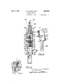
This invention relates to improvements in fluid-sampling devices of the type in which a predetermined fraction of a stream of fluid is taken H and collected. The invention will be fully understood from the following description, read in connection with the accompanying drawings, in which Fig. 1 is a central vertical section through a preferred form of the improved device;
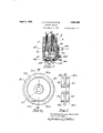
Fig. 2 is a side elevation, looking in the diipction of the arrows and along line II--II,
Fig. 3 is a transverse section on the line IIIIII, Fig. 2;
Fig. 4 is a transverse section on the line IV-IV, Fig. 2;
Fig. 5 is an enlarged transverse section on the line VV, Fig. 4;
Fig. 6 is an enlarged side elevation of the ratchet wheel;
Fig. 7 is a vertical sect-ion on line VII VII, Fig. 6; and Y Fig. 8 is a fragmentary view partly broken away showing the ratchet wheel and pin of fieferring to the drawings, reference numeral 1 denotes a housing-having vertical perforations 2 and 3 the centers of which are respectively on the parallel lines A and B, shown in Fig. 4. A pair of perforations 4 and 5 (see Figs. 1 and 5) are formed in the central part of the housing. These are alined respectively with perforations 2 and 3 having their centers in lines A and B respectively. Valve stems 2 and 3', carrying inlet valve 2 and outlet valve 3, are slidably fitted in the perforations 2 and 3, and valve stems 4 and 5, carrying valves 4 and 5, are slidably fitted in the perforations 4 and 5.
A bracket 6 is secured to the housing 1 by cap screws 7, or the like, which pass throng the arms 8 and 9 of the bracket. As will be seen, especially from Figs. 2 and 4, the bracket embraces the housing and rests upon it. The upper ends of the valve stems 2 and 3' are seated in recesses 10 and 11 in the body of the bracket. Springs 12 and 13, arranged respectively in these recesses, encircle the valve stems 2' and 3 and bear upon shoulders 14 and 15 formed thereon. The valve stems 1927. Serial R0. 172,915.
4' and 5' have springs 12 and 13, respectively, for returning the valves 4 and 5 to seated position. Suit-able packing is provided for the valve stems, as shown.
A ratchet wheel 26 is rotatable on a shaft 27, which is journalled in bearings formed in standards 28 and 29 rising from the top of bracket 6. This wheel has cam surfaces 30,
30 on its two sides, see especially Figs. 1, 6
and 8. Between these surfaces are depressed areas 30 and 30". The wheel 26 is rotated by a compound lever 31, 32 operating throu h a link 33 to move a pawl34 which engages t e teeth of the ratchet. The lever arm 31 is connected to the cross-head 35 of a pump, or to other suitable actuating means. A support 36 extends horizontall out from the bracket 6 to receive the end 0 the lever 31. A yoke 37 is mounted on the shaft 27 and pivotally supports the link 33 which actuates the pawl 34 The housing 1 has a lateral passageway 39 through which the fluid to be sampled is passed from a pipe 39. The passageway 39 intersects the perforation 2. Transverse passageway 40 affords communication between perforations 2 and 4 and passageway 41 between 3 and 5. A passageway 42 connects the perforations 4 and 5, and is closed at the outer end by a plug 42'. Passageways 40 and 41 are similarly closed by plugs 40,
41, respectively. A conduit 43, for withdrawing the sample, communicates with the perforation 3. The chambers 44, 45, beneath the valves 4 and 5", are closed externally by plugs 44 and 45.
The housing 1 is tapped to provide an openin 46, intersecting perforation 4, and adapte to allow flow of liquid through a I I Fig.5) and permits ready flow of t e sample.
The operation of the device is as follows, reference being made for example to its use in sampling a pumped stream of liquid:
Housing '1 is mounted in convenient relation to the pump and lever 81 is connected to cross-head 85. Passageway 39 receives liquid from the discharge line of the ump throu h i e 89. Reciprocation o the crossea orces pawl 34 forward, causing ratchet wheel 26 to turn in the direction of the arrow thereon (Fig. 1). In the position shown in that figure, pins 24 and are forced upwardly against depressed surfaces 80 and 80", on opposite sides of the ratchet wheel, by springs 12 and 13 operating through rocker arms 16 and 17. Valvestems 2' and 8' are pressed down on their seats by these springs. Accordin 1y, liquid can neither enter nor leave the ousing.
As ratchet wheel 26 turns, pin 24 is deressed by engagement with cam surface 30'.
his forces t e inner end of rocker arm 16 downward, raising valve stem 2' and forcing valve stem 4' down so that valve 4 is deressed slightly. This permits passage ofiquid from the ump line through passage-- way 89 around t e valve, and throu h open- 'n 46 back to the pump line. At (fix-is time vs ves 8 and 5' are closed. I
When cam surface 80' has passed beyond pin 24, this is lifted by spring 12' acting on rocker arm 16, until the pin rests against depressed surface 80. Consequentl ,valves 2 and 4' close. A sample of liqui is thus trapped in the passageways in housing 1. The volume of the sam le may be accurately predetermined by the dimensions selected for these passageways, which in'the ag regate may be referred to as the sample co ecting chamber. I
The cams 80 on the other side of the ratchet wheel are so arranged with res eat to cams 80' that they operate to open t e valves 3" and b a predetermined number of pump strokes after cams 30' have allowed the valves 2" and 4 to close. There is in all cases a positive segregation of inlet and discharge hases. T e liquid trapped in the housing ows from the conduit 43 into a receptacle for the samples. The opening of valve 5 serves to give access of air through 0 ening 47 e prefer to use a separate valve for admitting air, but it is feasi is to combine the functions of the air vent and liquid exhaust valves, as by allowing air to enter through the latter valve when opened.
It will be understood that the opening of by pin 25 forcing the rocker arm 17 downwar 1n the general manlisr above described for the actuation of arm withdrawing the trapped fluid.
The device described gives samples of constant volume at intervals which may be regulated by varying the number of teeth on the ratchet wheel 26, or the adjustment of the ratchet actuating levers, or both. In using the device to sample oil, we usually take a sample every fifty strokes of the pump. In this way a final composite sample which is truly representative of the oil is obtained. It will be noted that after the collection of each sample there is a flow of liquid through the device before the next sam la is taken. In this way all ossibility of iquid remaining stamant in t 1e sampler is avoided.
ur invention is not limited to the ratchet and lever means of actuation. For example, ins 24 and 25 or rocker arms 16 and 17 may e operated by pressure-responsive diaphragms, clock-work, motors, or the like. he valve seats may be removable and valves of the ball type may be used if desired. By the provision of an adjustable plu or the like the volume of the sample cham or may be varied as desired. (I
Various changes and alternative arrangements may be made within the sec e of the appended claims in which it is our intention to claim all novelty inherent in the invention as broadly as the prior art permits.
We claim:
1. Sampling mechanism comprising a chamber adapted to contain a sample, a conduit connected to the chamber, means for normally passing liquid through said chamber and conduit, valve means operative at predetermined intervals to trap1 chamber and means for wit trapped ii uid.
2. Sump in mechanism comprisingahousin having a c amber therein adapte to contam a sample only in one o erative position and to permit free flow of aids in another operative ducing fluid to be sampled rom a source of supply into said chamber, said housing having a assugeway for allowing flow from said chain or back to said source of supply, valve means operable to close said passageways thereby trapping the portion of the flul stream filling said chamber, and means for drawing the 8. Sampling mechanism comprising a housing, a sample-collecting chamber therein, said housing having a passageway for introducing fluid to be sampled from a source of supply into said chamber, said housing hayin a passageway for allowing flow from said c amber back to said source of supply, valve means operable to close said passageways, thereby tra ping the portion of the fluid stream fill ng sai chamber, and means for withdrawing by gravity flow the trapped fluid, while the liquid in the position, a passa eway for introvalve-controlled passage back to the source of su ply is closed.
4. Sampling, mechanism comprising a housing, a sample collecting chamber therein and having a passageway for the introduction of flllld to be sampled from a source of supply, said housing having also a passa way or allowing iquid to flow norma ly through said chamber, valve means operable to close said passagewa s, thereby trappin the portion of the fiui stream filling sai chamber, and means for withdrawing the trapped fluid.
5. Sampling mechanismcomprising a housing, a chamber therein, said housing having pgssageways through which a fluid stream to sampled may enter and leave said chamber, means for supplying a fluid stream for normal flow through said chamber valves controlling said assageways, a conduit for withdrawing flui from said chamber, an outlet valve controlling said conduit, means for actuating the in ct valve to trap a sample of the fluid in said chamber while said outlet valve is closed, and means for actuating the outlet valve and opening communication with the air to permit the trapped sample to flow from the chamber.
6. Mechanism according to claim 5 in which means .for ventin the chamber to the atmosphere are provide and connections by which said means is simultaneously operated with the outlet valve actuating means.
7. Samplin mechanism com rising a housing, a c amber therein, sai housin having a passageway through which a liqui J stream to be sam led may enter said chamber, a pair of in at valves ,controlling said passa way, a conduit for withdrawing liquid om said chamber, a pair of outlet valves controlling said conduit, means for opening the inlet valves and for closin the outlet valves to permit the filling o the chamber, means for closing the inlet valves to segregate the liquid i the chamber, and means operable subse uelii. to such closing for opening the outlet v ve to permit the liquid to flow from the chamber.
8. Sampling mechanism comprising a housing, our valve stems in pairs therein, valves carried by said valve stems and servcam surfaces arranged to operate the ins. 10. Mechanism according to claim 5, in which the means for actuating the rocfieir arms includes slidable pins for engaging e rocker arms, a ratchet wheel having cam surfaces arranged to operate the pins, and a lever and pawl connection to operate the ratchet wheel.
11. In a sampling device comprising a housing having a chamber and a passageway connecting the chamber with a source of the liquid to be sampled, the improvement which comprises a pair of valves arranged to control the inlet and outlet of said passagewa valve stems carrying said valves and shdably mounted in the housing, slpring means normally holding one of sai valves in closed position, means for simultaneously opening 0th valves, and means for releasing said first mentioned means, whereby the spring controlled valve is permitted to return to closed position.
AUSTIN EARLE CALKINS. LOUIS LASSEN.
ing respectivel for controllirrggkthe inlet and outlet of liqui a support, er arms pivotably mounted thereon between the valve stems of each pair and engagin said stems for simultaneous actuation, said ousing havtu ing an inlet passageway and an outlet pasway a chamber within the housing and with w ich these passageways communicats, and means for actuatin the rocker arms in succession to open and use the inlet and outlet valves, whereby samples of liquid are successivel segregated in the chamber and dischar therefrom.
,9, Mechanism according to claim 8, in which tcliedmeafishfir actuafting thegocfir armsm ues epms orengagm e rocker arms. and a member hing
Priority Applications (1)
| Application Number | Priority Date | Filing Date | Title |
|---|---|---|---|
| US172915A US1852445A (en) | 1927-03-04 | 1927-03-04 | Sampling device |
Applications Claiming Priority (1)
| Application Number | Priority Date | Filing Date | Title |
|---|---|---|---|
| US172915A US1852445A (en) | 1927-03-04 | 1927-03-04 | Sampling device |
Publications (1)
| Publication Number | Publication Date |
|---|---|
| US1852445A true US1852445A (en) | 1932-04-05 |
Family
ID=22629724
Family Applications (1)
| Application Number | Title | Priority Date | Filing Date |
|---|---|---|---|
| US172915A Expired - Lifetime US1852445A (en) | 1927-03-04 | 1927-03-04 | Sampling device |
Country Status (1)
| Country | Link |
|---|---|
| US (1) | US1852445A (en) |
Cited By (11)
| Publication number | Priority date | Publication date | Assignee | Title |
|---|---|---|---|---|
| US2534489A (en) * | 1945-07-02 | 1950-12-19 | Phillips Petroleum Co | Automatic sampler of liquid and gas phase streams |
| US2548193A (en) * | 1945-07-05 | 1951-04-10 | Bowser Inc | Liquid sampling apparatus |
| US2558387A (en) * | 1946-01-28 | 1951-06-26 | Gen Controls Co | Liquid sampler |
| US2972254A (en) * | 1957-07-18 | 1961-02-21 | Lambert Engineering Co Inc | Well flow periodic sampling mechanism |
| US2986940A (en) * | 1958-12-22 | 1961-06-06 | Barber Machinery Ltd | Sampling device |
| US20050016620A1 (en) * | 2002-04-26 | 2005-01-27 | Stephen Proulx | Disposable, sterile fluid transfer device |
| US20080022785A1 (en) * | 2003-12-23 | 2008-01-31 | Furey James F | Disposable, pre-sterilized fluid receptacle sampling device |
| US20090229671A1 (en) * | 2007-11-16 | 2009-09-17 | Millipore Corporation | Fluid transfer device |
| US20100158759A1 (en) * | 2008-12-18 | 2010-06-24 | Millipore Corporation | Device For The Transfer Of A Medium |
| US20100154569A1 (en) * | 2008-12-18 | 2010-06-24 | Millipore Corporation | Device For The Transfer Of A Medium |
| US8544497B2 (en) | 2009-10-30 | 2013-10-01 | Emd Millipore Corporation | Fluid transfer device and system |
-
1927
- 1927-03-04 US US172915A patent/US1852445A/en not_active Expired - Lifetime
Cited By (33)
| Publication number | Priority date | Publication date | Assignee | Title |
|---|---|---|---|---|
| US2534489A (en) * | 1945-07-02 | 1950-12-19 | Phillips Petroleum Co | Automatic sampler of liquid and gas phase streams |
| US2548193A (en) * | 1945-07-05 | 1951-04-10 | Bowser Inc | Liquid sampling apparatus |
| US2558387A (en) * | 1946-01-28 | 1951-06-26 | Gen Controls Co | Liquid sampler |
| US2972254A (en) * | 1957-07-18 | 1961-02-21 | Lambert Engineering Co Inc | Well flow periodic sampling mechanism |
| US2986940A (en) * | 1958-12-22 | 1961-06-06 | Barber Machinery Ltd | Sampling device |
| US20060142730A1 (en) * | 2002-04-26 | 2006-06-29 | Millipore Corporation | Disposable, sterile fluid transfer device |
| US7927316B2 (en) | 2002-04-26 | 2011-04-19 | Millipore Corporation | Disposable, sterile fluid transfer device |
| US20070106264A1 (en) * | 2002-04-26 | 2007-05-10 | Millipore Corporation | Disposable, sterile fluid transfer device |
| US20050016620A1 (en) * | 2002-04-26 | 2005-01-27 | Stephen Proulx | Disposable, sterile fluid transfer device |
| US9482351B2 (en) | 2002-04-26 | 2016-11-01 | Emd Millipore Corporation | Disposable, sterile fluid transfer device |
| US8579871B2 (en) | 2002-04-26 | 2013-11-12 | Emd Millipore Corporation | Disposable, sterile fluid transfer device |
| US8562572B2 (en) | 2002-04-26 | 2013-10-22 | Emd Millipore Corporation | Disposable, sterile fluid transfer device |
| US8517998B2 (en) | 2002-04-26 | 2013-08-27 | Emd Millipore Corporation | Disposable, sterile fluid transfer device |
| US20110197989A1 (en) * | 2002-04-26 | 2011-08-18 | Millipore Corporation | Disposable, sterile fluid transfer device |
| US20080022785A1 (en) * | 2003-12-23 | 2008-01-31 | Furey James F | Disposable, pre-sterilized fluid receptacle sampling device |
| US8549935B2 (en) | 2003-12-23 | 2013-10-08 | Emd Millipore Corporation | Disposable, pre-sterilized fluid receptacle sampling device |
| US20090019952A1 (en) * | 2003-12-23 | 2009-01-22 | Furey James F | Disposable, pre-sterilized fluid receptacle sampling device |
| US7921740B2 (en) * | 2003-12-23 | 2011-04-12 | Millipore Corporation | Disposable, pre-sterilized fluid receptacle sampling device |
| US8646342B2 (en) | 2003-12-23 | 2014-02-11 | Emd Millipore Corporation | Disposable, pre-sterilized fluid receptacle sampling device |
| US8690120B2 (en) | 2007-11-16 | 2014-04-08 | Emd Millipore Corporation | Fluid transfer device |
| US10247312B2 (en) | 2007-11-16 | 2019-04-02 | Emd Millipore Corporation | Fluid transfer device |
| US20090229671A1 (en) * | 2007-11-16 | 2009-09-17 | Millipore Corporation | Fluid transfer device |
| US9028779B2 (en) | 2008-12-18 | 2015-05-12 | Emd Millipore Corporation | Device for the transfer of a medium |
| US8539988B2 (en) | 2008-12-18 | 2013-09-24 | Emd Millipore Corporation | Device for the transfer of a medium |
| US20100158759A1 (en) * | 2008-12-18 | 2010-06-24 | Millipore Corporation | Device For The Transfer Of A Medium |
| US9120585B2 (en) | 2008-12-18 | 2015-09-01 | Emd Millipore Corporation | Device for the transfer of a medium |
| US9150825B2 (en) | 2008-12-18 | 2015-10-06 | Emd Millipore Corporation | Device for the transfer of a medium |
| US9279100B2 (en) | 2008-12-18 | 2016-03-08 | Emd Millipore Corporation | Device for the transfer of a medium |
| US9296983B2 (en) | 2008-12-18 | 2016-03-29 | Emd Millipore Corporation | Device for the transfer of a medium |
| US20100154569A1 (en) * | 2008-12-18 | 2010-06-24 | Millipore Corporation | Device For The Transfer Of A Medium |
| US8915264B2 (en) | 2009-10-30 | 2014-12-23 | Emd Millipore Corporation | Fluid transfer device and system |
| US8919365B2 (en) | 2009-10-30 | 2014-12-30 | Emd Millipore Corporation | Fluid transfer device and system |
| US8544497B2 (en) | 2009-10-30 | 2013-10-01 | Emd Millipore Corporation | Fluid transfer device and system |
Similar Documents
| Publication | Publication Date | Title |
|---|---|---|
| US1852445A (en) | Sampling device | |
| US3018791A (en) | Valve control apparatus | |
| US2130611A (en) | Valve | |
| US2240888A (en) | Milk sampler apparatus | |
| JPS6136171B2 (en) | ||
| US3516752A (en) | Measuring cell with gas and particle collection | |
| US2534489A (en) | Automatic sampler of liquid and gas phase streams | |
| US2192769A (en) | Cleaner | |
| US969282A (en) | Trap. | |
| US2463481A (en) | Apparatus for collecting liquid sediments | |
| CN107271221B (en) | Multi-station pollutant transportation water tank water sampler | |
| US2872818A (en) | Liquid sampling system | |
| US2274029A (en) | Flow responsive device | |
| US2012107A (en) | Multiple dispensing and measuring apparatus | |
| US2836978A (en) | Automatic liquid sample dispenser | |
| DE308005C (en) | ||
| DE1807394C3 (en) | Sampler of my device for drawing milk from a container | |
| US1963519A (en) | Liquid handling apparatus | |
| US1089390A (en) | Gas-analysis apparatus. | |
| US2133226A (en) | Control device | |
| US2702480A (en) | Liquid sampling apparatus | |
| US2059428A (en) | Apparatus for analyzing exhaust gases | |
| US2132766A (en) | Hand controlled valve | |
| US2400154A (en) | Power-operated sediment tester | |
| US1902219A (en) | Steam trap |